EP0882318B1 - Electrical multi-pole plug-and-socket-type connector with associated socket part - Google Patents
Electrical multi-pole plug-and-socket-type connector with associated socket part Download PDFInfo
- Publication number
- EP0882318B1 EP0882318B1 EP97906103A EP97906103A EP0882318B1 EP 0882318 B1 EP0882318 B1 EP 0882318B1 EP 97906103 A EP97906103 A EP 97906103A EP 97906103 A EP97906103 A EP 97906103A EP 0882318 B1 EP0882318 B1 EP 0882318B1
- Authority
- EP
- European Patent Office
- Prior art keywords
- socket
- modules
- plug
- type connector
- contact
- Prior art date
- Legal status (The legal status is an assumption and is not a legal conclusion. Google has not performed a legal analysis and makes no representation as to the accuracy of the status listed.)
- Expired - Lifetime
Links
Images
Classifications
-
- H—ELECTRICITY
- H01—ELECTRIC ELEMENTS
- H01R—ELECTRICALLY-CONDUCTIVE CONNECTIONS; STRUCTURAL ASSOCIATIONS OF A PLURALITY OF MUTUALLY-INSULATED ELECTRICAL CONNECTING ELEMENTS; COUPLING DEVICES; CURRENT COLLECTORS
- H01R13/00—Details of coupling devices of the kinds covered by groups H01R12/70 or H01R24/00 - H01R33/00
- H01R13/46—Bases; Cases
- H01R13/514—Bases; Cases composed as a modular blocks or assembly, i.e. composed of co-operating parts provided with contact members or holding contact members between them
-
- H—ELECTRICITY
- H01—ELECTRIC ELEMENTS
- H01R—ELECTRICALLY-CONDUCTIVE CONNECTIONS; STRUCTURAL ASSOCIATIONS OF A PLURALITY OF MUTUALLY-INSULATED ELECTRICAL CONNECTING ELEMENTS; COUPLING DEVICES; CURRENT COLLECTORS
- H01R13/00—Details of coupling devices of the kinds covered by groups H01R12/70 or H01R24/00 - H01R33/00
- H01R13/62—Means for facilitating engagement or disengagement of coupling parts or for holding them in engagement
- H01R13/621—Bolt, set screw or screw clamp
- H01R13/6215—Bolt, set screw or screw clamp using one or more bolts
-
- H—ELECTRICITY
- H01—ELECTRIC ELEMENTS
- H01R—ELECTRICALLY-CONDUCTIVE CONNECTIONS; STRUCTURAL ASSOCIATIONS OF A PLURALITY OF MUTUALLY-INSULATED ELECTRICAL CONNECTING ELEMENTS; COUPLING DEVICES; CURRENT COLLECTORS
- H01R13/00—Details of coupling devices of the kinds covered by groups H01R12/70 or H01R24/00 - H01R33/00
- H01R13/648—Protective earth or shield arrangements on coupling devices, e.g. anti-static shielding
- H01R13/658—High frequency shielding arrangements, e.g. against EMI [Electro-Magnetic Interference] or EMP [Electro-Magnetic Pulse]
- H01R13/6581—Shield structure
- H01R13/6582—Shield structure with resilient means for engaging mating connector
-
- H—ELECTRICITY
- H01—ELECTRIC ELEMENTS
- H01R—ELECTRICALLY-CONDUCTIVE CONNECTIONS; STRUCTURAL ASSOCIATIONS OF A PLURALITY OF MUTUALLY-INSULATED ELECTRICAL CONNECTING ELEMENTS; COUPLING DEVICES; CURRENT COLLECTORS
- H01R13/00—Details of coupling devices of the kinds covered by groups H01R12/70 or H01R24/00 - H01R33/00
- H01R13/648—Protective earth or shield arrangements on coupling devices, e.g. anti-static shielding
- H01R13/658—High frequency shielding arrangements, e.g. against EMI [Electro-Magnetic Interference] or EMP [Electro-Magnetic Pulse]
- H01R13/6591—Specific features or arrangements of connection of shield to conductive members
- H01R13/6594—Specific features or arrangements of connection of shield to conductive members the shield being mounted on a PCB and connected to conductive members
Definitions
- the invention relates to an electrical connector Type of multi-pin connector, its structure is modular with contact inserts based on a modular system and the opposite socket part is a corresponding one Has modularity, the respective contact inserts in the plug part and in the socket part in a mounting frame are clickable and for additional attachment of the Socket contact inserts in the socket part of the device mounting side can be plugged together to form a contact insert block.
- Modular electrical connectors are from the EP 0 523 491 A1 and from various catalogs or product publications known.
- a published product catalog 11/92 "Electrical components" from 2E Rolf Hiller becomes a modular connector system as a board connector described in accordance with DIN 41612, whose one Mounting frame modules that can be used as knife and female connectors are executed and for the respective use with contacts of different types by snapping can be equipped.
- This system does not have a connector housing and is in the male connector designed as a plug part more a separable board connector than an industrial connector assign.
- the Modules while maintaining a basic grid on a circuit board be attached.
- the Attachment takes place in a mounting frame that is on the Board side provided as a collection and alignment frame is.
- the modules inserted in these mounting frames are only available as plug-in, crimp or solder version.
- a universal use by means of a clamp or screw clamp connection for wires and strands and one in the modular system integrated PE contacting is not provided.
- the present invention has for its object to design an electrical connector of the type mentioned in a protection class IP65 not unusual for electrical connectors so that when taking advantage of modular electrical contact inserts, a compact electrical connector with PE contacting can be integrated if necessary.
- the disadvantages of the known prior art are to be minimized and, for use cases without the need for equipotential bonding with the same plug area, additional utilization of the PE contact area on the narrow side of the plug connector which is not required in these use cases is made possible by contact modules.
- the number of contacts per connector and its installation volume can be increased for such applications.
- this version should correspond to protection class IP65 and, for each connector size, partly with a plastic sleeve housing for use on devices, as well as in a second version with a metal housing for heavier industrial applications with extreme environmental conditions and additional EMC protection with no difference in size compared to the plastic housing Size and different contact inserts can be used.
- Another feature is by minimization the wall thicknesses of the connector side mounting frame like the mounting frame of the device side, optimal use of the Connector area for the number of modules to be inserted to enable. This is achieved in that a variant of the construction of the receiving frame resiliently installed PE metal parts leading contacting is dispensed with, which is usually in one piece at the ends of the longitudinal direction of the connector are firmly connected to the mounting frame.
- socket part of the electrical connector which is usually on the mounting frame on the device or add-on side or on an industrial 19 "rack is attached, in its form as a counterpart to the plug part without PE connection, as well as to one Plug part to be used with PE modules.
- the mounting frame for use without a PE connection as Counterpart to the connector side to a maximum of Connector modules designed.
- the mounting frame for use with PE contacts is the mounting frame in its module division of the position the connector-side modules adapted and also has an insertable bridge made of electrically conductive metal tape or round wire with one in the mounting frame snap-in PE module connected at the other end of the socket is. This has the advantage that only a further one PE connection, be it as a conductor track on a circuit board or as a freely clampable conductor got to.
- contact inserts are also advantageous to snap the contact inserts together the attachment or device side with locking means the side faces of the individual modules into a block that for additional stability of the contact inserts in the Socket part and beyond in the entire connector leads.
- the combination of contact inserts is also advantageous for contacting a circuit board and contact inserts for connecting further flexible electrical Ladder.
- Each of these different contact inserts is with a module of a different type of connection technology via locking pieces provided on the side of these modules or dovetail guides into a block connectable.
- Another feature is that for EMC protection provided constructive arrangement of a shield plate between the sleeve housing intended for this purpose made of metal and one for positioning the sleeve housing mounting frame provided on the on-site device front, which is also the receiving part of the device side Socket contact modules is.
- This shield plate encloses by the device side the mounting frame, so that at the same time after inserting the shield plate with the mounting frame in the device connection opening a contact with the edge of the Device front opening over several on the long side the receiving frame supporting resilient sections the shield plate is provided.
- the protection class IP65 of the entire connector design is achieved becomes a contact area provided groove in the sleeve housing wall of the plastic and / or metal housing and one inserted therein and for Contact surface of the connector protruding cord seal achieved by screwing the connector grommet sealing against a device wall between the two parts works.
- This construction is advantageous and inexpensive, because this creates a connector housing with additional Seal to the device wall and the associated additional installation space can be omitted.
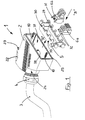
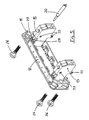
- Fig. 1 shows a first part of an electrical connector (1), the plug part, consisting of a sleeve housing (2), a receiving frame (5) and at least one in this receiving frame (5) snap-in contact module (6a, 6b), a PG screw connection (4) for mechanical and sealing Fastening a conductor cable (3) with the inside usual clamping and sealing elements, the fastening screws (10) for attaching the sleeve housing (2) to one Front of a device wall (13), as shown in FIGS. 3 and 6 is shown and advantageously in a groove the contact surface of the housing grommet (25), which together with the PG screw connection (4) provide a seal of the entire electrical connector in IP65 enables.
- the receiving opening (37) of the grommet housing (2) has one rectangular cross section with formed on the long sides (38) Contact surfaces with the long sides (39) of the elongated Interact with the receiving frame (5).
- the individual wires of the conductor cable are of a predetermined length after slipping on the cable gland with Strain relief (4) in the screw opening of the sleeve housing (2) and then for a clamp connection prepared. Furthermore, the shooting frame (5) with the order different or the same Contact modules (6a, 6b) by simply snapping them in the joining direction "B" equipped.
- the receiving frame (5) is advantageous and inexpensive made of plastic and has for attachment the contact modules (6a, 6b) are constructed and pieces protruding against the joining direction "B" (30), on the inside of the receiving frame (5) Undercuts (29) for receiving at right angles to Joining direction "B" of the contact module (6a, 6b) protruding Locking pieces (31) are provided. This connection is in Unjoined state of the receiving frame (5) in the sleeve housing (2) without great effort due to slight bending the mounting frame (5) to release, so that a contact module (6a, 6b) can be easily moved into its position can.
- the contact module (6a, 6b) in the receiving frame (5) When the contact modules (6a, 6b) in the receiving frame (5), the individual conductors of the Conductor cable (3) connected to the contact modules (6a, 6b) become.
- the contact module (6a, 6b) is in its constructive training has been advantageously provided that the actuators of the clamp connection to the long side (39, 39a) of the receiving frame (5) show and through the protruding pieces (30) of the receiving frame (5) are not be covered.
- the receiving frame (5) After connecting all individual conductors of the conductor cable (3) the receiving frame (5) with engaged contact modules (6a, 6b) in the joining direction "B" into the sleeve housing (2) pushed, the individual conductor of the conductor cable (3) find space inside the sleeve housing (5).
- the mounting frame (5) is fastened by means of fastening elements (28) 2 with the sleeve housing (2) in the joining direction "B” screwed inside the sleeve housing.
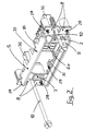
- Fig. 2 shows the perspective in part equipped mounting frame (5) of a variant for PE contacting from view "A”, the above Locking piece recordings (30) of the receiving frame (5) with the undercuts (29) are illustrated.
- FIG. such fixed PE contacts (7) in a mounting frame (5) provides and at the same time the side continued assembly of contact modules (6a, 6b) not with special needs.
- the constructive design of this snap and thus firmly connected to the mounting frame (5) PE modules (7) in the form and grid of the contact modules (6a) preferably the interchangeable use of PE socket counterparts (15) on the device side.
- the PE socket modules (15) can both with free conductor connection as well as with plug or solder connections for PCB contacting be executed.
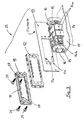
- Fig. 3 is the mounting side (device side), namely that Socket part 35, with which to connect to a device front cover (13) necessary components shown.
- the constructive version of the mounting frame (11) as a mounting and positioning flange for the sleeve housing (2) on the one hand and on the other as a leading mounting frame (11) for the counterparts socket modules (14a, 14b, 15).
- the socket modules (14a, 14b, 15) can according to the Connector side with the same mutual order be fitted by snapping, so that the necessary for this Snap technology using elements 29 to 32 in Fig. 1 and 2 of the connector side is used.
- connector modules to clip together into blocks (14) according to FIG. 3.
- each socket module (14a, 14b, 15) usual locking means (33), such as conical pointing towards each other Pins and undercut holes and / or Dovetail guides and grooves are provided.
- locking means such as conical pointing towards each other Pins and undercut holes and / or Dovetail guides and grooves are provided.
- socket modules (14b) for a free one Conductor connection can be made with the solderable or press-in PCB variant the socket modules (14a) by means of lateral connectivity (33) snapped together to form blocks (14) become.
- the module blocks (14) locked together can are soldered to the circuit board (19) and are in their entirety as a module block (14) in the mounting frame (11) can be inserted and locked. This is the mounting frame (11) by means of the connecting elements (26) from the plug side forth (Fig.
- PE socket modules (15) are also connected to the provided at one end of the module block (14) PE socket modules (15) as a counterpart to the connector variant provided with PE modules (7).
- PE contact modules (15) are on pluggable on the device side but not with the mounting frame (11) firmly connected PE contact modules (15) in their upper opened housing part (15) and that of the printed circuit board (19) opposite side with resilient contact elements (28) see Fig. 5, equipped, in which the angled electrically conductive end pieces (27) of the bridge (17) are inserted can be and thus a contact for forwarding provided on a PE socket module clamp connector is the electrical connection to the circuit board or as shown in Fig. 3 and Fig. 5 to free PE conductors (20).
- a shield plate (12) is proposed, which on the device side before joining the mounting frame (11) the front cover (13) over the mounting frame (11) is put over and together with this on the front cover (13) is attached, the resilient electrically conductive shield plate system contacts (34) an electrical Contact with the inner edge (13a) of the front cover opening produce.
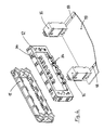
- FIG. 4 is the EMC variant with the PE contact a printed circuit board shown, wherein the device front to clarify the detail and the opening of which is not shown.
- the resilient shield contact contacts (34) with the inner edge of the receiving opening can contact a device front, so that the mounting mounting flanges (16) not necessarily a connection with the shield plate (12), as the front cover of the housing (13) of the device for example by a Paint layer can be electrically isolated.
- 4 is shown an application in which the metal parts of the mounting mounting flanges (16) partly with a conductor track (18) a circuit board (19) designed to be contactable are and on the other hand a connection to the front cover of the housing (13) using the metal parts of the mounting mounting flanges (16) can produce.
- the bridge (17) is at its end pieces (27) angular, preferably in the embodiment shown bent at right angles and contacted by the above End pieces (27) electrically conductive contact spring elements (28) of the PE socket module (15) in its bridge (17) open upper case area.
- the electrical contact is preferred to a pin contact as a counterpart to that in the plug part provided PE module (7) equipped with contact spring element, this pin contact of the socket module (15) again in one piece with the contact spring elements (28) is.
- These socket modules (15) also have lateral ones Latching means (33) for stringing together into one Module block (14).
Abstract
Description
Die Erfindung betrifft einen elektrischen Steckverbinder der Gattung der mehrpoligen Steckverbinder, dessen Aufbau modular mit Kontakteinsätzen nach einem Baukastensystem ausgeführt ist und dessen gegenteiliges Buchsenteil eine korrespondierende Modularität aufweist, wobei die jeweiligen Kontakteinsätze im Steckerteil und im Buchsenteil in einem Aufnahmerahmen einrastbar sind und zur zusätzlichen Befestigung der Buchsen-Kontakteinsätze im Buchsenteil der Geräteanbauseite zu einem Kontakteinsatzblock aneinandergesteckt werden können.The invention relates to an electrical connector Type of multi-pin connector, its structure is modular with contact inserts based on a modular system and the opposite socket part is a corresponding one Has modularity, the respective contact inserts in the plug part and in the socket part in a mounting frame are clickable and for additional attachment of the Socket contact inserts in the socket part of the device mounting side can be plugged together to form a contact insert block.
Modular aufgebaute elektrische Steckverbinder sind aus der
EP 0 523 491 A1 sowie aus verschiedenen Katalogen oder Produktdruckschriften
bekannt. In einem veröffentlichten Produktkatalog
11/92 "Elektrische Bauteile" der Fa. 2E Rolf
Hiller wird ein modulares Stecksystem als Platinensteckverbinder
in Anlehnung an DIN 41612 beschrieben, deren in einen
Aufnahmerahmen einsetzbare Module als Messer- und Federleisten
ausgeführt sind und für die jeweilige Verwendung
mit Kontakten unterschiedlicher Ausprägung durch Einrasten
bestückt werden können. Dieses System besitzt kein Steckergehäuse
und ist in der als Steckerteil ausgeführten Messerleiste
mehr einem trennbaren Platinenanschluß als einem Industriestecker
zuzuordnen. Je nach Bestückung können die
Module unter Beibehaltung eines Grundrasters auf einer Leiterplatte
befestigt werden. Die
Befestigung erfolgt in einem Aufnahmerahmen, der auf der
Platinenseite als Sammel- und Ausrichtrahmen vorgesehen
ist. Die in diesen Aufnahmerahmen eingesteckten Module sind
nur als Steck-, Crimp- oder Lötausführung erhältlich. Eine
universelle Verwendung mittels Klemm- oder Schraubklemmanschluß
für Drähte und Litzen und eine in das Modularsystem
integrierte PE-Kontaktierung ist nicht vorgesehen.Modular electrical connectors are from the
EP 0 523 491 A1 and from various catalogs or product publications
known. In a published
In den veröffentlichten Katalogen der CONTACT Connectors
950331 "EPIC Baureihe MC", "Concept - Das modulare Steckverbindersystem",
INNOVATION, Deckblatt Steckverbinder,
Weidmüller, Amphenol C 146 Modular-Katalog, euro publishing
2/94 werden ebenfalls modulare Steckverbinder eines gemeinsamen
Systems beschrieben, die in einen Rahmen einsetz- und
einrastbar sind. Die einzelnen Module sind bei diesem System
über seitliche Führungsrippen und korrespondierende,
in Steckrichtung verlaufende Nuten im Aufnahmerahmen geführt
und über Rasthaken mit diesem befestigt. Die Module
sind sehr robust und damit voluminös ausgeführt, was zu einer
Vergrößerung des Kontakt-Rastermaßes führt. Zum Potentialausgleich
zwischen dem Steckerteil und dem Buchsenteil
sind seitlich am Rahmen und außerhalb der Modulanordnung an
der Schmalseite des Steckverbinders voreilende PE-Metallkontakte
vorgesehen, die zur seitlichen Abfederung der Kontaktverbindung
zusätzlichen Einbauraum benötigt. Dies geht
bei Steckverbindungen ohne benötigten Potentialausgleich zu
Lasten der Anzahl der Kontakte pro Steckverbinder. Hierzu
sind die Anbau-/Sockelgehäuse und die Tüllengehäuse in einer
robusten Ausführung den besonderen Anfordernissen eines
schweren Einsatzes angepaßt worden und in aller Regel aus
Metall hergestellt. Die hierbei vorliegende Form der Gehäuse
ist auf ein vorgesehenes mechanisches Gelenk-Verriegelungssystem
abgestimmt, was zusätzlichen Einbauraum für den
gesamten elektrischen Steckverbinder benötigt.In the published catalogs of the CONTACT Connectors
950331 "EPIC series MC", "Concept - The modular connector system",
INNOVATION, connector cover sheet,
Weidmüller, Amphenol C 146 modular catalog,
Der vorliegenden Erfindung liegt die Aufgabe zugrunde, einen
elektrischen Steckverbinder der eingangs genannten Art
in einer für elektrische Steckverbinder nicht unüblichen
Schutzart IP65 so auszugestalten, daß bei Ausnutzung der
Vorteile von modularen elektrischen Kontakteinsätzen ein
kompakter elektrischer Steckverbinder mit im Bedarfsfall
integrierbarer PE-Kontaktierung entsteht.
In seinem Aufbau sollen die Nachteile des bekannten Standes
der Technik minimiert und für Einsatzfälle ohne Bedarf eines
Potentialausgleichs bei gleich großer Steckerfläche eine
zusätzliche Ausnutzung der in diesen Einsatzfällen nicht
benötigten PE-Kontaktfläche an der Schmalseite des Steckverbinders
durch Kontaktmodule ermöglicht werden. Somit
kann für derartige Einsatzfälle die Anzahl der Kontakte pro
Steckverbinder und dessen Einbauvolumen erhöht werden. Diese
Ausführung soll bei gleichen Abmessungen der Schutzart
IP65 entsprechen und pro Steckverbindergröße einesteils mit
einem Kunststofftüllengehäuse für den Einsatz an Geräten,
wie auch in einer zweiten Ausführung mit einem Metallgehäuse
für schwerere industrielle Einsätze mit extremen Umgebungsbedingungen
und zusätzlichem EMV-Schutz ohne Größenunterschied
zum Kunststoffgehäuse bei gleicher Baugröße und
unterschiedlichen Kontakteinsätzen eingesetzt werden können.The present invention has for its object to design an electrical connector of the type mentioned in a protection class IP65 not unusual for electrical connectors so that when taking advantage of modular electrical contact inserts, a compact electrical connector with PE contacting can be integrated if necessary.
In its structure, the disadvantages of the known prior art are to be minimized and, for use cases without the need for equipotential bonding with the same plug area, additional utilization of the PE contact area on the narrow side of the plug connector which is not required in these use cases is made possible by contact modules. Thus, the number of contacts per connector and its installation volume can be increased for such applications. With the same dimensions, this version should correspond to protection class IP65 and, for each connector size, partly with a plastic sleeve housing for use on devices, as well as in a second version with a metal housing for heavier industrial applications with extreme environmental conditions and additional EMC protection with no difference in size compared to the plastic housing Size and different contact inserts can be used.
Es ist vorgesehen, an sich bekannte Leiterplatten-MiniaturSteckverbinder mit einem zueinander passenden Rastermaß in Gruppen zu einem Modul zusammenzufassen und so zu modifizieren, daß diese Module einerseits als Steckerteil des Tüllengehäuses, wie auch anderseits als Buchsenteil auf der Anschluß- oder Geräteseite in einem Aufnahmerahmen angeordnet werden können. Die Anordnung ist konstruktiv derart gelöst, daß die Betätigungselemente oder -öffnungen zur Längsseite des Aufnahmerahmens zeigen, damit die Verdrahtung der einzelnen Klemmstellen erleichtert wird. Somit können mehrere Module mit unterschiedlichen Kontakteinsätzen für Leistungs- und/oder Signalübertragung in Schraubklemm- oder Federkraftklemmtechnik kombiniert und entsprechend dem vorgegebenen Rastermaß des Aufnahmerahmens in einer frei wählbaren Reihenfolge angeordnet werden..It is provided, known miniature PCB connectors with a matching pitch in Combine groups into one module and modify it in such a way that these modules on the one hand as a plug part of the Grommet housing, as well as on the other hand as a socket part on the Connection or device side arranged in a mounting frame can be. The arrangement is structurally solved such that the actuators or openings for Show the long side of the mounting frame so that the wiring of the individual terminal points is facilitated. Consequently can have multiple modules with different contact inserts for power and / or signal transmission in screw terminal or spring clamp technology combined and accordingly the predetermined grid dimension of the receiving frame in one freely selectable order can be arranged ..
Ein weiteres Merkmal besteht darin, durch eine Minimierung der Wandstärken des Aufnahmerahmens der Steckerseite wie des Anbaurahmens der Geräteseite, eine optimale Nutzung der Steckverbinderfläche für die Anzahl der einzusteckenden Module zu ermöglichen. Dies wird dadurch erreicht, daß bei einer Variante der Konstruktion des Aufnahmerahmens auf fest an diesem installierte federnde PE-Metallteile zur voreilenden Kontaktierung verzichtet wird, die üblicherweise an den Enden der Längsrichtung des Steckverbinders einstückig fest mit dem Aufnahmerahmen verbunden sind.Another feature is by minimization the wall thicknesses of the connector side mounting frame like the mounting frame of the device side, optimal use of the Connector area for the number of modules to be inserted to enable. This is achieved in that a variant of the construction of the receiving frame resiliently installed PE metal parts leading contacting is dispensed with, which is usually in one piece at the ends of the longitudinal direction of the connector are firmly connected to the mounting frame.
Für den Fall eines Bedarfes an voreilenden PE-Kontakten wird ein spezieller, auf die Modularität der Steckverbindermodule abgestimmter Aufnahmerahmen als Anbausatz vorgesehen, bei dem an den äußeren Enden des Aufnahmerahmens in Längsrichtung PE-Kontakte in Modulform mit einem halben Modulrastermaß vorgesehen sind, die zusammen ein ganzes Modul ergeben und miteinander über eine längs auf der Innenseite des Rahmens befestigten Brücke aus elektrisch leitendem Material als Flachband oder Runddraht verbunden werden. An diesem PE-Modul im Tüllengehäuse ist ein mit dem Leiterkabel mitgeführter PE-Leiter anschließbar.In the event of a need for leading PE contacts becomes a special, on the modularity of the connector modules coordinated mounting frame provided as a mounting kit, in which at the outer ends of the receiving frame in Longitudinal direction PE contacts in module form with half a module pitch are provided, which together form an entire module surrender and together along a lengthways on the inside of the frame attached bridge made of electrically conductive material can be connected as flat ribbon or round wire. On This PE module in the sleeve housing is one with the conductor cable Carried PE conductor can be connected.
Eine weitere Variante besteht darin, das Buchsenteil des elektrischen Verbinders, welches üblicherweise am Anbaurahmen auf der Geräte- oder Anbauseite oder an einem Industrie-19"-Rack befestigt wird, in seiner Ausprägung als Gegenstück zum Steckerteil ohne PE-Anschluß, wie auch zu einem Steckerteil mit PE-Modulen zu verwenden. Hierfür ist der Anbaurahmen für den Einsatzfall ohne PE-Anschluß als Gegenpart zur Steckerseite auf eine maximale Anzahl von Verbindermodulen ausgelegt. Für den Einsatz mit PE-Kontakten ist der Anbaurahmen in seiner Modulteilung der Position der steckerseitigen Module angepaßt und besitzt ebenfalls eine einsteckbare Brücke aus elektrisch leitendem Metallband oder Runddraht, die mit einem in den Aufnahmerahmen einrastbaren PE-Modul am anderen Buchsenteilende verbunden ist. Dies hat den Vorteil, daß nur ein weiterführender PE-Anschluß, sei es als Leiterbahn auf einer Leiterplatte oder als frei anklemmbarer Leiter, befestigt werden muß.Another variant is the socket part of the electrical connector, which is usually on the mounting frame on the device or add-on side or on an industrial 19 "rack is attached, in its form as a counterpart to the plug part without PE connection, as well as to one Plug part to be used with PE modules. For this is the mounting frame for use without a PE connection as Counterpart to the connector side to a maximum of Connector modules designed. For use with PE contacts is the mounting frame in its module division of the position the connector-side modules adapted and also has an insertable bridge made of electrically conductive metal tape or round wire with one in the mounting frame snap-in PE module connected at the other end of the socket is. This has the advantage that only a further one PE connection, be it as a conductor track on a circuit board or as a freely clampable conductor got to.
Vorteilig ist außerdem das Aneinanderrasten der Kontakteinsätze der Anbau- oder Geräteseite mit Verrastungsmittel an den Seitenflächen der einzelnen Module zu einem Block, das zu einer zusätzlichen Stabilität der Kontakteinsätze im Buchsenteil und darüber hinaus im gesamten Steckverbinder führt. Vorteilig ist auch die Kombination von Kontakteinsätzen zur Kontaktierung mit einer Leiterplatte und Kontakteinsätzen zum Anschluß weiterführender flexibler elektrischer Leiter. Jeder dieser unterschiedlichen Kontakteinsätze ist mit einem Modul einer anders gearteten Verbindungstechnik über seitlich an diesen Modulen vorgesehene Raststücke oder Schwalbenschwanzführungen zu einem Block fest verbindbar.It is also advantageous to snap the contact inserts together the attachment or device side with locking means the side faces of the individual modules into a block that for additional stability of the contact inserts in the Socket part and beyond in the entire connector leads. The combination of contact inserts is also advantageous for contacting a circuit board and contact inserts for connecting further flexible electrical Ladder. Each of these different contact inserts is with a module of a different type of connection technology via locking pieces provided on the side of these modules or dovetail guides into a block connectable.
Ein weiteres Merkmal besteht in der für einen EMV-Schutz vorgesehenen konstruktiven Anordnung eines Schirmbleches zwischen dem für diesen Zweck vorgesehenen Tüllengehäuse aus Metall und einem zur Positionierung des Tüllengehäuses an der anbauseitigen Gerätefront vorgesehenen Aufnahmerahmen, der gleichzeitig auch Aufnahmeteil der geräteseitigen Buchsenkontaktmodule ist. Dieses Schirmblech umschließt von der Geräteseite her den Aufnahmerahmen, so daß gleichzeitig nach dem Einstecken des Schirmbleches mit dem Anbaurahmen in die Geräteanschlußöffnung ein Kontakt mit der Kante der Gerätefrontseitenöffnung über mehrere auf der Längsseite des Aufnahmerahmens sich abstützende federnde Teilstücke des Schirmbleches vorgesehen ist.Another feature is that for EMC protection provided constructive arrangement of a shield plate between the sleeve housing intended for this purpose made of metal and one for positioning the sleeve housing mounting frame provided on the on-site device front, which is also the receiving part of the device side Socket contact modules is. This shield plate encloses by the device side the mounting frame, so that at the same time after inserting the shield plate with the mounting frame in the device connection opening a contact with the edge of the Device front opening over several on the long side the receiving frame supporting resilient sections the shield plate is provided.
Andererseits besteht die Möglichkeit, den Stecker und die Gerätefrontseite über die Anbauflansche mit PE-Anschlüssen einer Leiterplatte zu verbinden. Hierzu sind die Metallteile als Befestigungselemente des Anbauflansches so ausgebildet, daß eine Kontaktierung mit einer Leiterbahn einer Leiterplatte möglich ist.On the other hand, there is the possibility of the plug and the Front of the device via the mounting flanges with PE connections to connect a circuit board. For this, the metal parts designed as fastening elements of the mounting flange, that contacting a conductor track of a circuit board is possible.
Die Erreichung der Schutzart IP65 der gesamten Steckverbinder-Konstruktion wird dabei über eine zur Kontaktfläche vorgesehenen Nut in der Tüllengehäusewand des Kunststoff- und/oder Metallgehäuse und einer darin eingelegten und zur Kontaktfläche des Steckverbinders vorstehenden Schnurdichtung erreicht, die durch das Anschrauben der Steckverbindertülle an eine Gerätewand abdichtend zwischen beiden Teilen wirkt. Diese Konstruktion ist vorteilhaft und preiswert, weil dadurch ein Steckverbinder-Anbaugehäuse mit zusätzlicher Dichtung zur Gerätewand und der damit verbundene zusätzliche Einbauraum entfallen kann.The protection class IP65 of the entire connector design is achieved becomes a contact area provided groove in the sleeve housing wall of the plastic and / or metal housing and one inserted therein and for Contact surface of the connector protruding cord seal achieved by screwing the connector grommet sealing against a device wall between the two parts works. This construction is advantageous and inexpensive, because this creates a connector housing with additional Seal to the device wall and the associated additional installation space can be omitted.
Weitere Merkmale, Vorteile und Anwendungsmöglichkeiten der vorliegenden Erfindung ergeben sich aus der nachfolgenden Beschreibung von Ausführungsbeispielen anhand der Zeichnungen und der Zeichnung selbst, die in Zusammenhang mit den Figuren näher erläutert werden. Dabei bilden alle beschriebenen und/oder bildlich dargestellten Merkmale für sich oder in einer beliebigen Kombination den Gegenstand der vorliegenden Erfindung, unabhängig von ihrer Zusammenfassung in den Schutzansprüchen oder deren Rückbeziehung. Es zeigt
- Fig. 1
- einen ersten Teil eines Tüllengehäuses (2) eines elektrischen Steckverbinders (1) in einer perspektivischen Darstellung mit angeschlossenem mehradrigem Leiterkabel (3), Kabelverschraubung (4) mit Zugentlastung, herausgezogenem Aufnahmerahmen (5) und zwei unterschiedliche in diesem Aufnahmerahmen (5) einrastbare Kontaktmodule (6a, 6b),
- Fig. 2
- eine perspektivische Darstellung des Aufnahmerahmens (5) mit PE-Kontakten in einer Ansicht "A" und mit eingerasteten Kontaktmodulen (6a, 6b), einstückig am Aufnahmerahmen (5) angeordneten PE-Modulen (7) und deren Verbindung mit einem elektrisch leitenden Metallteil (8) über eine am Aufnahmerahmen (5) anliegenden Brücke (9) und der Position der Befestigungsschrauben (10) des Tüllengehäuses (2),
- Fig. 3
- eine perspektivische Darstellung der Anbauteile einer Gerätefront in der Ausführung mit PE-Kontakten und deren Anordnung im Anbaurahmen (11) auf der Geräteseite, mit eingelegter Brücke (17) , der Position des Schirmbleches (12), einer Frontblende (13) eines Gerätes und einer möglichen Anordnung eines Modulblockes (14) von Leiterplattenbuchsenmodulen (14a, 14b) und Anbauflanschen (16), sowie PE-Module (15) für die Kontaktierung freier elektrischer Leiter (20) .
- Fig. 4
- eine perspektivische Darstellung der Anordnung zur Verbindung von Anbaurahmen (11), Schirmblech (12) und Anbauflansche (16) bei einer Ausführung ohne PE-Kontaktierung, bei der das Schirmblech (12) mittels federnder Kontakte (34) mit der Innenkante der Aufnahmeöffnung (13a) der Gerätefrontseite (13) kontaktiert und wobei über die Anbauflansche (16) eine Verbindung des Schirmbleches (12) und der Gerätefrontseite (13) mit Leiterbahnen (18) einer Leiterplatte (19) ermöglicht wird und gleichzeitig über die Anbauflansche (16) eine Befestigung der Leiterplatte (19) an der Gerätefrontseite (13) vorgesehen ist und
- Fig. 5
- eine perspektivische Darstellung der Anordnung von PE-Modulen (15) am Anbaurahmen (11) mit der Darstellung der Position der einsteckbaren Brücke (17) am Aufnahmerahmen (11) und deren seitliche Kontaktierung mit den Federkontakten (28) der PE-Module (15), die hier vorzugsweise als Verbinder für freie Leiter (20) dargestellt sind.
- Fig. 1
- a perspective view of a first part of a grommet housing (2) of an electrical connector (1) with a connected multi-core conductor cable (3), cable gland (4) with strain relief, pulled-out mounting frame (5) and two different contact modules that can be snapped into this mounting frame (5) 6a, 6b),
- Fig. 2
- a perspective view of the mounting frame (5) with PE contacts in a view "A" and with engaged contact modules (6a, 6b), PE modules (7) arranged in one piece on the mounting frame (5) and their connection to an electrically conductive metal part ( 8) via a bridge (9) resting on the receiving frame (5) and the position of the fastening screws (10) of the sleeve housing (2),
- Fig. 3
- a perspective view of the attachments of a device front in the version with PE contacts and their arrangement in the mounting frame (11) on the device side, with inserted bridge (17), the position of the shield plate (12), a front panel (13) of a device and one possible arrangement of a module block (14) of printed circuit board socket modules (14a, 14b) and mounting flanges (16), as well as PE modules (15) for contacting free electrical conductors (20).
- Fig. 4
- a perspective view of the arrangement for connecting the mounting frame (11), shield plate (12) and mounting flanges (16) in a version without PE contact, in which the shield plate (12) by means of resilient contacts (34) with the inner edge of the receiving opening (13a ) contacted the front of the device (13) and a connection of the shield plate (12) and the front of the device (13) with conductor tracks (18) of a circuit board (19) is made possible via the mounting flanges (16) and at the same time an attachment via the mounting flanges (16) the circuit board (19) is provided on the front of the device (13) and
- Fig. 5
- a perspective view of the arrangement of PE modules (15) on the mounting frame (11) with the representation of the position of the plug-in bridge (17) on the mounting frame (11) and their lateral contact with the spring contacts (28) of the PE modules (15) , which are preferably shown here as connectors for free conductors (20).
Fig. 1 zeigt einen ersten Teil eines elektrischen Verbinders (1), dem Steckerteil, bestehend aus einem Tüllengehäuse (2), einem Aufnahmerahmen (5) und mindestens einem in diesen Aufnahmerahmen (5) einrastbaren Kontaktmodul (6a, 6b), einer PG-Verschraubung (4) zur mechanischen und abdichtenden Befestigung eines Leiterkabels (3) mit den darin üblichen Klemm- und Dichtelementen, den Befestigungsschrauben (10) zur Befestigung des Tüllengehäuses (2) an einer Frontseite einer Gerätewand (13), wie sie in Fig. 3 und 6 dargestellt ist und einer vorteilhafterweise in einer Nut der Kontaktfläche der Gehäusetülle eingelegten Dichtung (25), die zusammen mit der PG-Verschraubung (4) eine Abdichtung des gesamten elektrischen Steckverbinders in IP65 ermöglicht. Dies erspart eine zusätzliche Dichtung in einem Sockelteil, sowie das Sockelteil selbst. Diese Teile werden um die Befestigungsteile (28), zu sehen in Fig. 2, ergänzt. Die Aufnahmeöffnung (37) des Tüllengehäuses (2) hat einen rechteckigen Querschnitt mit an den Längsseiten (38) gebildeten Anlageflächen, die mit den Längsseiten (39) des länglichen Aufnahmerahmen (5) zusammenwirken. Fig. 1 shows a first part of an electrical connector (1), the plug part, consisting of a sleeve housing (2), a receiving frame (5) and at least one in this receiving frame (5) snap-in contact module (6a, 6b), a PG screw connection (4) for mechanical and sealing Fastening a conductor cable (3) with the inside usual clamping and sealing elements, the fastening screws (10) for attaching the sleeve housing (2) to one Front of a device wall (13), as shown in FIGS. 3 and 6 is shown and advantageously in a groove the contact surface of the housing grommet (25), which together with the PG screw connection (4) provide a seal of the entire electrical connector in IP65 enables. This saves an additional seal in one Base part, as well as the base part itself. These parts are to the fastening parts (28), see in Fig. 2, added. The receiving opening (37) of the grommet housing (2) has one rectangular cross section with formed on the long sides (38) Contact surfaces with the long sides (39) of the elongated Interact with the receiving frame (5).
Nach der Abisolation des Außenmantels des Leiterkabels (3) in einer vorgegebenen Länge werden die Einzeladern des Leiterkabels nach dem Überstreifen der Kabelverschraubung mit Zugentlastung (4) in die Verschraubungsöffnung des Tüllengehäuses (2) eingesteckt und anschließend für eine Klemmkontaktierung vorbereitet. Weiterhin wird der Aufnahmerahmen (5) mit der Reihenfolge unterschiedlicher oder gleicher Kontaktmodule (6a, 6b) durch einfaches Einrasten in Fügerichtung "B" bestückt. Der Aufnahmerahmen (5) ist vorteilhaft und preiswert aus Kunststoff gefertigt und hat zur Befestigung der Kontaktmodule (6a, 6b) konstruktiv ausgebildete und gegen die Fügerichtung "B" vorstehende Stücke (30), an denen auf der Innenseite des Aufnahmerahmens (5) Hinterschneidungen (29) zur Aufnahme von rechtwinklig zur Fügerichtung "B" des Kontaktmoduls (6a, 6b) abstehende Raststücke (31) vorgesehen sind. Diese Verbindung ist im ungefügten Zustand des Aufnahmerahmens (5) in das Tüllengehäuse (2) ohne größeren Kraftaufwand durch geringes Aufbiegen des Aufnahmerahmens (5) zu lösen, so daß ein Kontaktmodul (6a, 6b) ohne weiteres in seiner Position versetzt werden kann.After stripping the outer sheath of the conductor cable (3) The individual wires of the conductor cable are of a predetermined length after slipping on the cable gland with Strain relief (4) in the screw opening of the sleeve housing (2) and then for a clamp connection prepared. Furthermore, the shooting frame (5) with the order different or the same Contact modules (6a, 6b) by simply snapping them in the joining direction "B" equipped. The receiving frame (5) is advantageous and inexpensive made of plastic and has for attachment the contact modules (6a, 6b) are constructed and pieces protruding against the joining direction "B" (30), on the inside of the receiving frame (5) Undercuts (29) for receiving at right angles to Joining direction "B" of the contact module (6a, 6b) protruding Locking pieces (31) are provided. This connection is in Unjoined state of the receiving frame (5) in the sleeve housing (2) without great effort due to slight bending the mounting frame (5) to release, so that a contact module (6a, 6b) can be easily moved into its position can.
Im komplett eingerasteten Zustand der Kontaktmodule (6a, 6b) im Aufnahmerahmen (5) können die einzelnen Leiter des Leiterkabels (3) an die Kontaktmodule (6a, 6b) angeschlossen werden. Hierzu ist das Kontaktmodul (6a, 6b) in seiner konstruktiven Ausbildung vorteilhaft so vorgesehen worden, daß die Betätigungselemente der Klemmverbindung zur Längsseite (39, 39a) des Aufnahmerahmens (5) zeigen und durch die vorstehenden Stücke (30) des Aufnahmerahmens (5) nicht verdeckt werden. When the contact modules (6a, 6b) in the receiving frame (5), the individual conductors of the Conductor cable (3) connected to the contact modules (6a, 6b) become. For this purpose, the contact module (6a, 6b) is in its constructive training has been advantageously provided that the actuators of the clamp connection to the long side (39, 39a) of the receiving frame (5) show and through the protruding pieces (30) of the receiving frame (5) are not be covered.
Nach dem Anschluß aller einzelnen Leiter des Leiterkabels (3) wird der Aufnahmerahmen (5) mit eingerasteten Kontaktmodulen (6a, 6b) in Fügerichtung "B" in das Tüllengehäuse (2) geschoben, wobei die einzelnen Leiter des Leiterkabels (3) im Inneren des Tüllengehäuses (5) Platz finden. Der Aufnahmerahmen (5) wird mittels Befestigungselementen (28) nach Fig. 2 mit dem Tüllengehäuse (2) in Fügerichtung "B" im inneren des Tüllengehäuses verschraubt. Nach dem Festsitz des Aufnahmerahmens (5) ist eine Entnahme eines Verbindermoduls (6a, 6b) nicht mehr möglich, da die inneren Anlageflächen (38) des Tüllengehäuses (2) als Formelement dem Aufweiten der Längsseiten (39) des Aufnahmerahmens (5) entgegenwirken.After connecting all individual conductors of the conductor cable (3) the receiving frame (5) with engaged contact modules (6a, 6b) in the joining direction "B" into the sleeve housing (2) pushed, the individual conductor of the conductor cable (3) find space inside the sleeve housing (5). The The mounting frame (5) is fastened by means of fastening elements (28) 2 with the sleeve housing (2) in the joining direction "B" screwed inside the sleeve housing. After the tight fit of the receiving frame (5) is a removal of a connector module (6a, 6b) no longer possible because the inner Contact surfaces (38) of the sleeve housing (2) as a shaped element expanding the long sides (39) of the receiving frame (5) counteract.
Zur Abstützung und zur Positionierung der Kontaktmodule in Fügerichtung "B" sind seitlich vorstehende Abstützungen (32) am Kunststoffgehäuseteil des Kontaktmoduls (6a, 6b) vorgesehen, die sich auf dem Rand des Aufnahmerahmens (5) in Fügerichtung "B" abstützen und mit seitlichen Abstützungen (32) den Rand der Längsseite (39) des Aufnahmerahmen (5) umgreifen und einer Bewegung des Kontaktmoduls (6a, 6b) quer zur Fügerichtung "B" sowie einem Aufweiten der Aufnahmerahmens (5) entgegenwirken beziehungsweise ein Lösen des Verbindermoduls (6a, 6b) verhindern.For supporting and positioning the contact modules in Joining direction "B" are protruding supports on the side (32) on the plastic housing part of the contact module (6a, 6b) provided, which are on the edge of the receiving frame (5) Support in joining direction "B" and with side supports (32) the edge of the long side (39) of the receiving frame (5) grasp and a movement of the contact module (6a, 6b) transverse to the joining direction "B" and a widening of the receiving frame (5) counteract or loosen the Prevent connector module (6a, 6b).
Fig. 2 zeigt in einer perspektivischen Ansicht den teilweise bestückten Aufnahmerahmen (5) einer Ausführungsvariante für PE-Kontaktierung aus der Ansicht "A", wobei die vorstehenden Raststückaufnahmen (30) des Aufnahmerahmens (5) mit den Hinterschneidungen (29) verdeutlicht sind. Fig. 2 shows the perspective in part equipped mounting frame (5) of a variant for PE contacting from view "A", the above Locking piece recordings (30) of the receiving frame (5) with the undercuts (29) are illustrated.
Häufig ist es erforderlich, über eine Verkabelung ein elektrisches Potential auf ein Gerät zum Schutz der darin befindlichen elektronischen Bauteile zu führen und zu übertragen. In einer Ausführungsvariante des elektrischen Verbinders (1) ist die Übernahme dieses elektrischen Potentials von der Steckerseite zur Geräteseite dadurch gegeben, daß hierfür ein in Form eines Kontaktmoduls (6a, 6b) konstruiertes PE-Modul (7) vorgesehen ist, das ein einsetzbares PE-Buchsenmodul (15) in Fig. 3 auf der Geräteseite kontaktiert.It is often necessary to use electrical wiring Potential for a device to protect the inside to guide and transmit electronic components. In a variant of the electrical connector (1) is the assumption of this electrical potential given from the connector side to the device side that for this a constructed in the form of a contact module (6a, 6b) PE module (7) is provided, which can be used Contacted PE socket module (15) in Fig. 3 on the device side.
In Fig. 2 wird deshalb eine vorteilhafte Konstruktion vorgeschlagen, die solche festen PE-Kontakte (7) in einem Aufnahmerahmen (5) vorsieht und gleichzeitig die seitlich fortzuführende Bestückung von Kontaktmodulen (6a, 6b) nicht behindert. Die konstruktive Gestaltung dieser einrastbaren und damit fest mit dem Aufnahmerahmen (5) verbundenen PE-Module (7) in Form und Raster der Kontaktmodule (6a) ermöglicht vorzugsweise den austauschbaren Einsatz von PE-Buchsen-Gegenstücken (15) auf der Geräteseite. Die PE-Buchsenmodule (15) können sowohl mit freiem Leiteranschluß wie auch mit Steck- oder Lötanschlüssen für eine Leiterplattenkontaktierung ausgeführt sein.An advantageous construction is therefore proposed in FIG. such fixed PE contacts (7) in a mounting frame (5) provides and at the same time the side continued assembly of contact modules (6a, 6b) not with special needs. The constructive design of this snap and thus firmly connected to the mounting frame (5) PE modules (7) in the form and grid of the contact modules (6a) preferably the interchangeable use of PE socket counterparts (15) on the device side. The PE socket modules (15) can both with free conductor connection as well as with plug or solder connections for PCB contacting be executed.
Hierzu ist vorteilhaft vorgesehen, in einer konstruktiven
Variante den Aufnahmerahmen (5) und den Anbaurahmen (11)
mit je einer halben Kontaktmodulbreite des Kontaktmoduls
(6a) in einer Ausführung als PE-Modul (7) an beiden Stirnseiten
einstückig mit dem Aufnahmerahmen (5) auszubilden
und ein vorgefertigtes elektrisch leitendes Metallteil (8)
mit einer verbundenen Brücke (9) zwischen den äußeren Metallteilen
(8) einzulegen, die wiederum seitlich mit der
Klemmverbindung des Leiteranschlusses des PE-Moduls (7)
elektrisch kontaktiert. In einer anderen konstruktiven Variante
ist ein einsteckbares und verrastbares PE-Modul (7)
der gleichen halben Kontaktmodulbreite möglich, wobei die
kontaktierenden Metallteile auf diese Konstruktion abgestimmt
sind. Die Ausführung des Anbaurahmens mit PE-Kontaktierung
ist in einem Anbausatz zusammengefügt. Die
zueinander passenden PE-Module 7, 15 des Steckverbinders 1
und des Buchsenteils 35 (Fig. 3) haben voreilende Kontakte
36.This is advantageously provided in a constructive
Variant of the mounting frame (5) and the mounting frame (11)
with half the contact module width of the contact module
(6a) in a design as a PE module (7) on both ends
to be formed in one piece with the receiving frame (5)
and a prefabricated electrically conductive metal part (8)
with a connected bridge (9) between the outer metal parts
(8) insert, which in turn laterally with the
Clamp connection of the conductor connection of the PE module (7)
electrically contacted. In another constructive variant
is a plug-in and lockable PE module (7)
the same half contact module width possible, the
Contacting metal parts matched to this construction
are. The design of the add-on frame with PE contact
is assembled in a mounting kit. The
In Fig. 3 ist die Anbauseite (Geräteseite), nämlich das
Buchsenteil 35, mit den zur Verbindung mit einer Gerätefrontabdeckung
(13) notwendigen Bauteilen dargestellt. Vorteilhaft
bei dieser Ausführung ist die konstruktive Ausführung
des Anbaurahmens (11) als Befestigungs- und Positionierflansch
für das Tüllengehäuse (2) einerseits und andererseits
als führender Anbaurahmen (11) für die als Gegenstücke
zur Steckerseite positionierten Buchsenmodule (14a,
14b, 15).In Fig. 3 is the mounting side (device side), namely that
Die Buchsenmodule (14a, 14b, 15) können entsprechend der
Steckerseite mit der gleichen gegenseitigen Reihenfolge
durch Einrasten bestückt werden, so daß die hierfür notwendige
Einrasttechnik mittels der Elemente 29 bis 32 in Fig.
1 und 2 der Steckerseite verwendet wird.The socket modules (14a, 14b, 15) can according to the
Connector side with the same mutual order
be fitted by snapping, so that the necessary for this
Snap
In der Praxis sind die geräteseitigen Buchsenmodule (14a) mit Leiterplatten (19) galvanisch wie auch mittels Einpreßtechnik verbunden. Hierfür ist es von Vorteil, die Verbindermodule zu Blöcken (14) nach Fig. 3 zusammenzuclipsen. In practice, the socket modules (14a) on the device side with printed circuit boards (19) galvanically as well as by means of press-in technology connected. For this it is advantageous to use the connector modules to clip together into blocks (14) according to FIG. 3.
Nach Fig. 5 sind seitlich an jedem Buchsenmodul (14a, 14b, 15) übliche Verrastmittel (33), wie zueinander zeigende konische Zapfen und hinterschnittene Bohrungen und/oder Schwalbenschwanzführungen und -nuten, vorgesehen. Aber auch die Verwendung von Buchsenmodulen (14b) für einen freien Leiteranschluß können mit der löt- oder einpreßbaren Leiterplattenvariante der Buchsenmodule (14a) mittels der seitlichen Verbindbarkeit (33) zu Blöcken (14) zusammengerastet werden. Die zusammengerasteten Modulblöcke (14) können auf der Leiterplatte (19) verlötet werden und sind in ihrer Gesamtheit als Modulblock (14) in dem Anbaurahmen (11) einsteck- und verrastbar. Dazu wird der Anbaurahmen (11) mittels der Verbindungselemente (26) von der Steckerseite her (Fig. 3) an der Gehäusefrontabdeckung (13) gehalten, wobei der Verbinderblock (14) von der Rückseite der Gehäusefrontabdeckung (13) in den Anbaurahmen (11) in der oben beschriebenen Form gerastet wird, so daß die Gehäusefrontabdeckung zwischen Anbaurahmen (11) und Buchsenmodule (14a, 14b, 15) eingeklemmt wird. Zusätzlich sind auf der Platinenseite des Gehäusefrontabdeckung (13) an beiden Seiten des Modulblockes (14) Anbau-Befestigungsflansche (16) vorgesehen, die einesteils mit den Buchsenmodulen (14a, 14b, 15) seitlich verrastet werden können, aber andererseits mittels der Verbindungselemente (26) den Anbaurahmen (11) an die Gehäusefrontabdeckung (13) ziehen, positionieren und befestigen.5 are laterally on each socket module (14a, 14b, 15) usual locking means (33), such as conical pointing towards each other Pins and undercut holes and / or Dovetail guides and grooves are provided. But also the use of socket modules (14b) for a free one Conductor connection can be made with the solderable or press-in PCB variant the socket modules (14a) by means of lateral connectivity (33) snapped together to form blocks (14) become. The module blocks (14) locked together can are soldered to the circuit board (19) and are in their entirety as a module block (14) in the mounting frame (11) can be inserted and locked. This is the mounting frame (11) by means of the connecting elements (26) from the plug side forth (Fig. 3) held on the front cover (13), wherein the connector block (14) from the back of the Front cover (13) in the mounting frame (11) in the Form described above is snapped so that the front cover of the housing between mounting frame (11) and socket modules (14a, 14b, 15) is pinched. In addition are on the Board side of the front cover (13) on both sides of the module block (14) add-on mounting flanges (16) provided that one part with the socket modules (14a, 14b, 15) can be locked laterally, but on the other hand the mounting frame by means of the connecting elements (26) Pull (11) on the front cover (13), position and fasten.
Auch auf der Geräteseite ist eine Brücke (17) zur Verbindung des jeweils an einem Ende des Modulblocks (14) vorgesehenen PE-Buchsenmodule (15) als Gegenstück zur Steckervariante mit PE-Modulen (7) vorgesehen. Hierfür sind die auf der Geräteseite steckbaren aber nicht mit dem Anbaurahmen (11) fest verbundenen PE-Kontaktmodule (15) in ihrem oberen geöffneten Gehäuseteil (15) und der der Leiterplatte (19) abgewandten Seite mit federnden Kontaktelementen (28), zu sehen in Fig. 5, ausgestattet, in die die abgewinkelten elektrisch leitenden Endstücke (27) der Brücke (17) eingesteckt werden können und somit eine Kontaktierung zur Weiterleitung an ein PE-Buchsenmodul-Klemmverbinder vorgesehen ist, der die elektrische Verbindung zur Leiterplatte oder wie in Fig. 3 und Fig. 5 dargestellt an freie PE-Leiter (20) vornimmt.There is also a bridge (17) on the device side for connection the provided at one end of the module block (14) PE socket modules (15) as a counterpart to the connector variant provided with PE modules (7). For that they are on pluggable on the device side but not with the mounting frame (11) firmly connected PE contact modules (15) in their upper opened housing part (15) and that of the printed circuit board (19) opposite side with resilient contact elements (28) see Fig. 5, equipped, in which the angled electrically conductive end pieces (27) of the bridge (17) are inserted can be and thus a contact for forwarding provided on a PE socket module clamp connector is the electrical connection to the circuit board or as shown in Fig. 3 and Fig. 5 to free PE conductors (20).
In einer EMV-geschützten Variante des elektrischen Verbinders (1) wird ein Schirmblech (12) vorgeschlagen, welches auf der Geräteseite vor dem Fügen des Anbaurahmens (11) an die Gehäusefrontabdeckung (13) über den Anbaurahmen (11) gestülpt wird und mit diesem zusammen an der Gehäusefrontabdeckung (13) befestigt wird, wobei die federnden elektrisch leitenden Schirmblech-Anlagekontakte (34) eine elektrische Kontaktierung mit der Innenkante (13a) der Gehäusefrontabdeckungsöffnung herstellen.In an EMC-protected variant of the electrical connector (1) a shield plate (12) is proposed, which on the device side before joining the mounting frame (11) the front cover (13) over the mounting frame (11) is put over and together with this on the front cover (13) is attached, the resilient electrically conductive shield plate system contacts (34) an electrical Contact with the inner edge (13a) of the front cover opening produce.
Hierzu ist in Fig. 4 die EMV-Variante mit der PE-Kontaktierung einer Leiterplattenbahn dargestellt, wobei zur Verdeutlichung der Detaildarstellung die Gerätefrontseite und deren Öffnung nicht dargestellt ist. Bereits in der Fig. 3 ist verdeutlicht, daß die federnden Schirmblech-Anlagekontakte (34) mit der Innenkante der Aufnahmeöffnung einer Gerätefront kontaktieren können, so daß die Anbau-Befestigungsflansche (16) nicht unbedingt eine Verbindung mit dem Schirmblech (12) herstellen müssen, da die Gehäusefrontabdeckung (13) des Gerätes zum Beispiel durch eine Lackschicht elektrisch isoliert sein kann. In Fig. 4 ist ein Einsatzfall dargestellt, in dem die Metallteile der Anbau-Befestigungsflansche (16) einesteils mit einer Leiterbahn (18) einer Leiterplatte (19) kontaktierbar ausgeführt sind und andernteils eine Verbindung zur Gehäusefrontabdekkung (13) mittels der Metallteile des Anbau-Befestigungsflansche (16) herstellen kann.4 is the EMC variant with the PE contact a printed circuit board shown, wherein the device front to clarify the detail and the opening of which is not shown. Already in Fig. 3 shows that the resilient shield contact contacts (34) with the inner edge of the receiving opening can contact a device front, so that the mounting mounting flanges (16) not necessarily a connection with the shield plate (12), as the front cover of the housing (13) of the device for example by a Paint layer can be electrically isolated. 4 is shown an application in which the metal parts of the mounting mounting flanges (16) partly with a conductor track (18) a circuit board (19) designed to be contactable are and on the other hand a connection to the front cover of the housing (13) using the metal parts of the mounting mounting flanges (16) can produce.
In Fig. 5 ist weiterhin die Verbindung und Anordnung zwischen elektrisch leitender Brücke (17) und den PE-Buchsenmodulen (15) zur PE-Weiterleitung an freie Leiter (20) dargestellt. Die Brücke (17) ist dabei an ihren Endstücken (27) winklig, in der dargestellten Ausführung vorzugsweise rechtwinklig abgebogen und kontaktiert durch die vorstehenden Endstücke (27) elektrisch leitende Kontaktfederelemente (28) des PE-Buchsenmoduls (15) in dessen zur Brücke (17) offenen oberen Gehäusebereich. Im unteren Bereich des PE-Buchsenmoduls (15) ist der elektrischen Kontakt vorzugsweise zu einem Stiftkontakt als Gegenstück zu dem im Steckerteil vorgesehen PE-Modul (7) mit Kontaktfederelement ausgestattet, wobei dieser Stiftkontakt des Buchsenmoduls (15) wiederum mit den Kontaktfederelementen (28) einstückig verbunden ist. Auch diese Buchsenmodule (15) besitzen seitliche Verrastungsmittel (33) zur Aneinanderreihung zu einem Modulblock (14). 5 is the connection and arrangement between electrically conductive bridge (17) and the PE socket modules (15) for PE forwarding to free conductors (20). The bridge (17) is at its end pieces (27) angular, preferably in the embodiment shown bent at right angles and contacted by the above End pieces (27) electrically conductive contact spring elements (28) of the PE socket module (15) in its bridge (17) open upper case area. In the lower area of the PE socket module (15) the electrical contact is preferred to a pin contact as a counterpart to that in the plug part provided PE module (7) equipped with contact spring element, this pin contact of the socket module (15) again in one piece with the contact spring elements (28) is. These socket modules (15) also have lateral ones Latching means (33) for stringing together into one Module block (14).
- 11
- SteckverbinderConnectors
- 22nd
- TüllengehäuseSleeve housing
- 33rd
- Leiterkabel, mehradrigConductor cable, multi-core
- 44th
- Kabelverschraubung mit ZugentlastungCable gland with strain relief
- 55
- AufnahmerahmenMounting frame
- 66
- KontaktmodulContact module
- 6a6a
- Kontaktmodul 8-fach8-way contact module
- 6b6b
- Kontaktmodul 2-fachDouble contact module
- 77
- PE-ModulPE module
- 88th
- Metallteil, elektrisch leitendMetal part, electrically conductive
- 99
- Brücke, steckerseitigBridge, on the connector side
- 1010th
- BefestigungsschraubeFastening screw
- 1111
- AnbaurahmenMounting frame
- 1212th
- SchirmblechShield plate
- 1313
- GehäusefrontabdeckungFront cover
- 1414
- ModulblockModule block
- 14a14a
- Buchsenmodul, steck-/einlötbarSocket module, pluggable / solderable
- 14b14b
- Buchsenmodul, freier LeiterabgangSocket module, free conductor outlet
- 1515
- PE-BuchsenmodulPE socket module
- 1616
- Anbau-BefestigungsflanschAttachment mounting flange
- 1717th
- Brücke, buchsenseitigBridge, on the socket side
- 1818th
- PE-LeiterbahnPE conductor track
- 1919th
- LeiterplatteCircuit board
- 2020th
- freier Leiterfree leader
- 2121
- Griffhaltung des BedienersGrip position of the operator
- 2222
- KennzeichnungsschildIdentification label
- 2323
- Vorsprunghead Start
- 2424th
- Griffseite Handle side
- 2525th
- Dichtungpoetry
- 2626
- BefestigungsschraubenMounting screws
- 2727
- BrückenendstückBridge end piece
- 2828
- PE-BuchsenmetallPE socket metal
- 2929
- RaststückaufnahmevertiefungRest piece recess
- 3030th
- RaststückaufnahmeRest piece holder
- 3131
- RaststückRest stop
- 3232
- seitliche Abstützunglateral support
- 3333
- seitliche Modulverrastunglateral module locking
- 3434
- Schirmblech-AnlagekontaktShield plate system contact
- 3535
- BuchsenteilSocket part
- 3636
- Voreilende KontakteLeading contacts
- 3737
- AufnahmeöffnungReceiving opening
- 3838
- Längsseite d. TüllengehäusesLong side d. Grommet housing
- 3939
- Längsseite d. AufnahmerahmensLong side d. Frame
Claims (10)
- Electrical multi-pole plug-and-socket-type connector with associated socket part, which both have a respective carrier for receiving contact modules which correspond with one another, whereby these contact modules are equipped with connections for a corresponding number of conductors,
characterised in that
in the carrier (5) of the plug-and-socket-type connector (1) as well as in the carrier (11) of the socket part (35) instead of at least one contact module (6a, 6b) two PE modules (7, 15) can optionally be used, which upon connection of the plug-and-socket-type connector (1) and the socket part (35) together have priority contacting (rapid) contacts (36), and in that a bridge (9, 17) made from an electrically conducting material and connecting the two PE modules (7, 15) respectively can be positioned on the respective carrier (5, 11). - A plug-and-socket-type connector according to Claim 1
characterised in that
the PE modules (7, 15) of the plug-and-socket-type connector and/or of the socket part (35) have a connection for a free conductor (20). - A plug-and-socket-type connector according to Claim 1 or Claim 2
characterised in that
the PE modules (15) of the socket part (35) have plug connections or soldered connections for the contacting of a circuit board (19). - A plug-and-socket-type connector according to Claim 3
characterised in that
PE modules (15) of the socket part (35) can be engaged with the circuit board (19) and mounting flanges (16) are securely positioned on the circuit board (19), whereby these mounting flanges (16) can be screwed together with the carrier (11) of the socket part (35) . - A plug-and-socket-type connector according to one of the Claims 1 to 4
characterised in that
the contact modules (6a, 6b) have a module width of equal division and the PE modules (7, 15) have half module width. - A plug-and-socket-type connector according to one of the Claims 1 to 5
characterised in that
the contact modules (6a, 6b) and the PE modules (7, 15) have a lateral means of engaging (33). - A plug-and-socket-type connector according to one of the Claims 1 to 6
characterised in that
the bridge (9, 17) connecting the PE modules (7, 15) consists of flat strip or round wire. - A plug-and-socket-type connector according to Claim 7
characterised in that
the bridge (9, 17) connecting the PE modules (7, 15) is positioned inside or outside on the carrier (5, 11). - A plug-and-socket-type connector according to Claim 7 or Claim 8
characterised in that
the bridge (17) of the socket part (35) connecting the PE modules (15) contacts with a screening plate surrounding the carrier (11), whereby this screening plate is positioned in connection with the socket case (2) of the plug-and-socket-type connector (1). - A plug-and-socket-type connector according to Claim 4 and Claim 9
characterised in that
instead of the PE modules (15) of the socket part (35) the mounting flanges (16) on the circuit board (19) are electrically connected to the screening plate (12) and to PE conductor paths (18) positioned on the circuit board (19) .
Applications Claiming Priority (3)
| Application Number | Priority Date | Filing Date | Title |
|---|---|---|---|
| DE29602740U DE29602740U1 (en) | 1996-02-21 | 1996-02-21 | Electrical connector |
| DE29602740U | 1996-02-21 | ||
| PCT/EP1997/000826 WO1997033347A1 (en) | 1996-02-21 | 1997-02-21 | Electrical multi-pole plug-and-socket-type connector with associated socket part |
Publications (2)
| Publication Number | Publication Date |
|---|---|
| EP0882318A1 EP0882318A1 (en) | 1998-12-09 |
| EP0882318B1 true EP0882318B1 (en) | 2000-05-31 |
Family
ID=8019578
Family Applications (1)
| Application Number | Title | Priority Date | Filing Date |
|---|---|---|---|
| EP97906103A Expired - Lifetime EP0882318B1 (en) | 1996-02-21 | 1997-02-21 | Electrical multi-pole plug-and-socket-type connector with associated socket part |
Country Status (8)
| Country | Link |
|---|---|
| US (1) | US6004163A (en) |
| EP (1) | EP0882318B1 (en) |
| JP (1) | JP3631761B2 (en) |
| CN (1) | CN1112744C (en) |
| AT (1) | ATE193621T1 (en) |
| DE (2) | DE29602740U1 (en) |
| ES (1) | ES2147436T3 (en) |
| WO (1) | WO1997033347A1 (en) |
Cited By (4)
| Publication number | Priority date | Publication date | Assignee | Title |
|---|---|---|---|---|
| DE102016120002A1 (en) | 2016-10-20 | 2018-04-26 | Phoenix Contact Gmbh & Co. Kg | Contact insert for a connector part |
| DE102016121966A1 (en) | 2016-11-16 | 2018-05-17 | Phoenix Contact Gmbh & Co. Kg | Contact insert for a connector part |
| DE202017101365U1 (en) | 2017-03-10 | 2018-06-12 | Phoenix Contact Gmbh & Co. Kg | Contact insert for a connector part |
| WO2018162136A1 (en) | 2017-03-10 | 2018-09-13 | Phoenix Contact Gmbh & Co. Kg | Contact insert for a plug connector part |
Families Citing this family (24)
| Publication number | Priority date | Publication date | Assignee | Title |
|---|---|---|---|---|
| DE19645782B4 (en) * | 1996-11-07 | 2005-11-10 | Weidmüller Interface Gmbh & Co. | Connectors |
| US6464537B1 (en) | 1999-12-29 | 2002-10-15 | Berg Technology, Inc. | High speed card edge connectors |
| JP2001297819A (en) * | 2000-03-01 | 2001-10-26 | Amphenol Tuchel Electronics Gmbh | Connector |
| USD433383S (en) * | 2000-04-27 | 2000-11-07 | Hon Hai Precision Ind. Co., Ltd. | Electrical connector |
| US7052331B2 (en) * | 2003-09-25 | 2006-05-30 | Maxwell Scott D | Symmetrically adjustable corrosion-resistant battery cable connector |
| DE202006013824U1 (en) * | 2006-09-09 | 2007-10-11 | Moeller Gmbh | Plug holder for at least one plug |
| US7320613B1 (en) * | 2007-03-28 | 2008-01-22 | Inventor's Group, Llc | Automatic locking electrical outlet |
| DE102008031990B3 (en) * | 2008-06-06 | 2010-04-15 | Siemens Aktiengesellschaft | Plug of a connector |
| EP2290758B1 (en) * | 2009-08-26 | 2016-09-07 | Wieland Electric GmbH | Industry connector |
| CN202453678U (en) * | 2012-02-13 | 2012-09-26 | 施耐德电器工业公司 | Man-machine interface device and control cabinet comprising same |
| DE102012101813B3 (en) * | 2012-03-05 | 2013-06-13 | Phoenix Contact Gmbh & Co. Kg | Connectors |
| DE102012110907B4 (en) * | 2012-11-13 | 2019-06-13 | Harting Electric Gmbh & Co. Kg | Holding frame for holding connector modules |
| CN103001055B (en) * | 2012-12-30 | 2016-04-20 | 无锡国丰电子科技有限公司 | A kind of socket with the group mechanism of unloading |
| NO2780523T3 (en) | 2014-06-25 | 2018-03-24 | ||
| DE102015106416B3 (en) | 2015-04-27 | 2016-06-02 | Harting Electric Gmbh & Co. Kg | Modular connector |
| EP3282526B1 (en) * | 2016-08-08 | 2020-12-30 | Tyco Electronics Svenska AB | Connection assembly |
| DE102017003198B4 (en) * | 2017-04-03 | 2018-10-31 | Harting Electric Gmbh & Co. Kg | Connector modular system with integrated data bus |
| DE102017129742A1 (en) * | 2017-12-13 | 2019-06-13 | Harting Electric Gmbh & Co. Kg | Compact mounting housing |
| BE1025936B1 (en) * | 2018-01-22 | 2019-08-21 | Phoenix Contact Gmbh & Co Kg | Modular system for manufacturing an electrical device |
| DE102019103562A1 (en) * | 2019-02-13 | 2020-08-13 | Harting Electric Gmbh & Co. Kg | Module frame |
| DE102019103772A1 (en) | 2019-02-13 | 2020-08-13 | Harting Electric Gmbh & Co. Kg | Protective conductor connection |
| DE102019115177A1 (en) * | 2019-06-05 | 2020-12-10 | Harting Electric Gmbh & Co. Kg | Modular PCB connector |
| TWI729616B (en) * | 2019-12-10 | 2021-06-01 | 台達電子工業股份有限公司 | Power plug |
| KR20210141887A (en) * | 2020-05-15 | 2021-11-23 | 현대모비스 주식회사 | Structure for preventing connector removal from electronic components in vehicle |
Family Cites Families (6)
| Publication number | Priority date | Publication date | Assignee | Title |
|---|---|---|---|---|
| DE2329334A1 (en) * | 1973-06-08 | 1975-01-02 | Daimler Benz Ag | CENTRAL PLUG CONNECTION |
| US4464003A (en) * | 1982-11-01 | 1984-08-07 | Amp Incorporated | Insulation displacing connector with programmable ground bussing feature |
| DE3781715T2 (en) * | 1986-04-22 | 1993-04-29 | Amp Inc | ELECTRICAL CONNECTOR ARRANGEMENT FOR DISTRIBUTING DIFFERENT POWER LEVELS ON A PRINTED CIRCUIT. |
| US4820169A (en) * | 1986-04-22 | 1989-04-11 | Amp Incorporated | Programmable modular connector assembly |
| US5125854A (en) * | 1991-07-16 | 1992-06-30 | Molex Incorporated | Modular electrical connector |
| DE29508095U1 (en) * | 1995-05-17 | 1995-07-20 | Hts Elektrotech Gmbh & Co Kg | Modular connector system |
-
1996
- 1996-02-21 DE DE29602740U patent/DE29602740U1/en not_active Expired - Lifetime
-
1997
- 1997-02-21 DE DE59701810T patent/DE59701810D1/en not_active Expired - Lifetime
- 1997-02-21 AT AT97906103T patent/ATE193621T1/en active
- 1997-02-21 WO PCT/EP1997/000826 patent/WO1997033347A1/en active IP Right Grant
- 1997-02-21 CN CN97192496A patent/CN1112744C/en not_active Expired - Fee Related
- 1997-02-21 JP JP53140097A patent/JP3631761B2/en not_active Expired - Fee Related
- 1997-02-21 EP EP97906103A patent/EP0882318B1/en not_active Expired - Lifetime
- 1997-02-21 ES ES97906103T patent/ES2147436T3/en not_active Expired - Lifetime
- 1997-02-21 US US09/125,136 patent/US6004163A/en not_active Expired - Lifetime
Cited By (5)
| Publication number | Priority date | Publication date | Assignee | Title |
|---|---|---|---|---|
| DE102016120002A1 (en) | 2016-10-20 | 2018-04-26 | Phoenix Contact Gmbh & Co. Kg | Contact insert for a connector part |
| EP3312940B1 (en) | 2016-10-20 | 2020-01-15 | Phoenix Contact GmbH & Co. KG | Contact insert for a connector part |
| DE102016121966A1 (en) | 2016-11-16 | 2018-05-17 | Phoenix Contact Gmbh & Co. Kg | Contact insert for a connector part |
| DE202017101365U1 (en) | 2017-03-10 | 2018-06-12 | Phoenix Contact Gmbh & Co. Kg | Contact insert for a connector part |
| WO2018162136A1 (en) | 2017-03-10 | 2018-09-13 | Phoenix Contact Gmbh & Co. Kg | Contact insert for a plug connector part |
Also Published As
| Publication number | Publication date |
|---|---|
| CN1112744C (en) | 2003-06-25 |
| ATE193621T1 (en) | 2000-06-15 |
| EP0882318A1 (en) | 1998-12-09 |
| CN1212081A (en) | 1999-03-24 |
| US6004163A (en) | 1999-12-21 |
| DE59701810D1 (en) | 2000-07-06 |
| ES2147436T3 (en) | 2000-09-01 |
| JP2000502495A (en) | 2000-02-29 |
| JP3631761B2 (en) | 2005-03-23 |
| WO1997033347A1 (en) | 1997-09-12 |
| DE29602740U1 (en) | 1996-04-11 |
Similar Documents
| Publication | Publication Date | Title |
|---|---|---|
| EP0882318B1 (en) | Electrical multi-pole plug-and-socket-type connector with associated socket part | |
| DE602005000149T2 (en) | Connection arrangement of an electrical device | |
| EP2005486B1 (en) | Electrical connecting device for flat conductors | |
| DE60004418T2 (en) | A branch junction box | |
| DE3909263C3 (en) | Electrical connection device | |
| DE60218961T2 (en) | Press-in busbar for power supply | |
| WO2014067849A1 (en) | Series module arrangement with an energy bus system | |
| DE102005050399B3 (en) | Connecting terminal e.g. print terminal, for use in printed circuit board, has spring force unit with leg spring punched out and molded from material strip for clamping electrical conductor and fastened in openings | |
| EP3734768A1 (en) | Electrical plug connector and electrical connector formed therewith | |
| DE4437316C2 (en) | Decentralized input / output module for electronic controls | |
| EP0849840B1 (en) | Multipole screened cable connector | |
| WO2021028077A1 (en) | 8 + 2 way xlr pcb female connector | |
| DE10041831B4 (en) | joint assembly | |
| EP0813765B1 (en) | Device connecting conductors or devices to a busbar in a busbar system | |
| EP0813269B1 (en) | Electrical connector | |
| DE3922072C2 (en) | ||
| DE3103455C2 (en) | Electrical connector, in particular for data technology | |
| EP3734771B1 (en) | Set of an electrical connector and a functional element | |
| DE102013007815B4 (en) | Swiveling connector and contacting method | |
| EP0330119A2 (en) | Plug connection for electrical cables | |
| DE4420674A1 (en) | Fastening clamp device for a connector frame | |
| DE10224841B4 (en) | Device for the electrical connection of contact points on adjacent printed circuit boards | |
| DE69725269T2 (en) | Electrical connector with pin holder | |
| EP1291983B1 (en) | Connecting unit for an electrical modul | |
| EP0895660A1 (en) | Cable plug-in connector with contact tongues provided with soldered connections and secured in an insulating body |
Legal Events
| Date | Code | Title | Description |
|---|---|---|---|
| PUAI | Public reference made under article 153(3) epc to a published international application that has entered the european phase |
Free format text: ORIGINAL CODE: 0009012 |
|
| 17P | Request for examination filed |
Effective date: 19980710 |
|
| AK | Designated contracting states |
Kind code of ref document: A1 Designated state(s): AT BE CH DE ES FR GB IT LI NL SE |
|
| GRAG | Despatch of communication of intention to grant |
Free format text: ORIGINAL CODE: EPIDOS AGRA |
|
| 17Q | First examination report despatched |
Effective date: 19990615 |
|
| GRAG | Despatch of communication of intention to grant |
Free format text: ORIGINAL CODE: EPIDOS AGRA |
|
| GRAH | Despatch of communication of intention to grant a patent |
Free format text: ORIGINAL CODE: EPIDOS IGRA |
|
| GRAH | Despatch of communication of intention to grant a patent |
Free format text: ORIGINAL CODE: EPIDOS IGRA |
|
| GRAA | (expected) grant |
Free format text: ORIGINAL CODE: 0009210 |
|
| AK | Designated contracting states |
Kind code of ref document: B1 Designated state(s): AT BE CH DE ES FR GB IT LI NL SE |
|
| REF | Corresponds to: |
Ref document number: 193621 Country of ref document: AT Date of ref document: 20000615 Kind code of ref document: T |
|
| REG | Reference to a national code |
Ref country code: CH Ref legal event code: NV Representative=s name: SCHMAUDER & PARTNER AG PATENTANWALTSBUERO Ref country code: CH Ref legal event code: EP |
|
| RIC1 | Information provided on ipc code assigned before grant |
Free format text: 7H 01R 13/518 A, 7H 01R 12/16 B, 7H 01R 13/658 B |
|
| REF | Corresponds to: |
Ref document number: 59701810 Country of ref document: DE Date of ref document: 20000706 |
|
| ITF | It: translation for a ep patent filed |
Owner name: ING. ZINI MARANESI & C. S.R.L. |
|
| GBT | Gb: translation of ep patent filed (gb section 77(6)(a)/1977) |
Effective date: 20000725 |
|
| ET | Fr: translation filed | ||
| REG | Reference to a national code |
Ref country code: ES Ref legal event code: FG2A Ref document number: 2147436 Country of ref document: ES Kind code of ref document: T3 |
|
| PLBE | No opposition filed within time limit |
Free format text: ORIGINAL CODE: 0009261 |
|
| STAA | Information on the status of an ep patent application or granted ep patent |
Free format text: STATUS: NO OPPOSITION FILED WITHIN TIME LIMIT |
|
| 26N | No opposition filed | ||
| REG | Reference to a national code |
Ref country code: GB Ref legal event code: IF02 |
|
| REG | Reference to a national code |
Ref country code: CH Ref legal event code: PFA Free format text: PHOENIX CONTACT GMBH & CO. TRANSFER- PHOENIX CONTACT GMBH & CO. KG |
|
| REG | Reference to a national code |
Ref country code: CH Ref legal event code: PCAR Free format text: SCHMAUDER & PARTNER AG PATENT- UND MARKENANWAELTE VSP;ZWAENGIWEG 7;8038 ZUERICH (CH) |
|
| PGFP | Annual fee paid to national office [announced via postgrant information from national office to epo] |
Ref country code: CH Payment date: 20140227 Year of fee payment: 18 Ref country code: SE Payment date: 20140224 Year of fee payment: 18 Ref country code: NL Payment date: 20140224 Year of fee payment: 18 |
|
| PGFP | Annual fee paid to national office [announced via postgrant information from national office to epo] |
Ref country code: BE Payment date: 20140225 Year of fee payment: 18 |
|
| PGFP | Annual fee paid to national office [announced via postgrant information from national office to epo] |
Ref country code: DE Payment date: 20140414 Year of fee payment: 18 |
|
| REG | Reference to a national code |
Ref country code: FR Ref legal event code: PLFP Year of fee payment: 19 |
|
| PGFP | Annual fee paid to national office [announced via postgrant information from national office to epo] |
Ref country code: IT Payment date: 20150225 Year of fee payment: 19 Ref country code: ES Payment date: 20150205 Year of fee payment: 19 |
|
| PGFP | Annual fee paid to national office [announced via postgrant information from national office to epo] |
Ref country code: GB Payment date: 20150220 Year of fee payment: 19 Ref country code: AT Payment date: 20150224 Year of fee payment: 19 Ref country code: FR Payment date: 20150223 Year of fee payment: 19 |
|
| PG25 | Lapsed in a contracting state [announced via postgrant information from national office to epo] |
Ref country code: BE Free format text: LAPSE BECAUSE OF NON-PAYMENT OF DUE FEES Effective date: 20150228 |
|
| REG | Reference to a national code |
Ref country code: DE Ref legal event code: R119 Ref document number: 59701810 Country of ref document: DE |
|
| REG | Reference to a national code |
Ref country code: NL Ref legal event code: V1 Effective date: 20150901 |
|
| REG | Reference to a national code |
Ref country code: SE Ref legal event code: EUG |
|
| PG25 | Lapsed in a contracting state [announced via postgrant information from national office to epo] |
Ref country code: NL Free format text: LAPSE BECAUSE OF NON-PAYMENT OF DUE FEES Effective date: 20150901 |
|
| REG | Reference to a national code |
Ref country code: CH Ref legal event code: PL |
|
| PG25 | Lapsed in a contracting state [announced via postgrant information from national office to epo] |
Ref country code: CH Free format text: LAPSE BECAUSE OF NON-PAYMENT OF DUE FEES Effective date: 20150228 Ref country code: LI Free format text: LAPSE BECAUSE OF NON-PAYMENT OF DUE FEES Effective date: 20150228 |
|
| PG25 | Lapsed in a contracting state [announced via postgrant information from national office to epo] |
Ref country code: SE Free format text: LAPSE BECAUSE OF NON-PAYMENT OF DUE FEES Effective date: 20150222 |
|
| PG25 | Lapsed in a contracting state [announced via postgrant information from national office to epo] |
Ref country code: DE Free format text: LAPSE BECAUSE OF NON-PAYMENT OF DUE FEES Effective date: 20150901 |
|
| REG | Reference to a national code |
Ref country code: AT Ref legal event code: MM01 Ref document number: 193621 Country of ref document: AT Kind code of ref document: T Effective date: 20160221 |
|
| GBPC | Gb: european patent ceased through non-payment of renewal fee |
Effective date: 20160221 |
|
| REG | Reference to a national code |
Ref country code: FR Ref legal event code: ST Effective date: 20161028 |
|
| PG25 | Lapsed in a contracting state [announced via postgrant information from national office to epo] |
Ref country code: AT Free format text: LAPSE BECAUSE OF NON-PAYMENT OF DUE FEES Effective date: 20160221 |
|
| PG25 | Lapsed in a contracting state [announced via postgrant information from national office to epo] |
Ref country code: IT Free format text: LAPSE BECAUSE OF NON-PAYMENT OF DUE FEES Effective date: 20160221 |
|
| PG25 | Lapsed in a contracting state [announced via postgrant information from national office to epo] |
Ref country code: FR Free format text: LAPSE BECAUSE OF NON-PAYMENT OF DUE FEES Effective date: 20160229 Ref country code: GB Free format text: LAPSE BECAUSE OF NON-PAYMENT OF DUE FEES Effective date: 20160221 |
|
| REG | Reference to a national code |
Ref country code: ES Ref legal event code: FD2A Effective date: 20180507 |
|
| PG25 | Lapsed in a contracting state [announced via postgrant information from national office to epo] |
Ref country code: ES Free format text: LAPSE BECAUSE OF NON-PAYMENT OF DUE FEES Effective date: 20160222 |