EP2003477B1 - Elektro-optische Hybrid-Steckverbindung zur Übertragung von hohen optischen Leistungen und elektrischen Signalen - Google Patents
Elektro-optische Hybrid-Steckverbindung zur Übertragung von hohen optischen Leistungen und elektrischen Signalen Download PDFInfo
- Publication number
- EP2003477B1 EP2003477B1 EP07011761A EP07011761A EP2003477B1 EP 2003477 B1 EP2003477 B1 EP 2003477B1 EP 07011761 A EP07011761 A EP 07011761A EP 07011761 A EP07011761 A EP 07011761A EP 2003477 B1 EP2003477 B1 EP 2003477B1
- Authority
- EP
- European Patent Office
- Prior art keywords
- optical
- ferrule
- plug
- fibre
- hybrid
- Prior art date
- Legal status (The legal status is an assumption and is not a legal conclusion. Google has not performed a legal analysis and makes no representation as to the accuracy of the status listed.)
- Not-in-force
Links
- 230000003287 optical effect Effects 0.000 title claims description 40
- 239000000835 fiber Substances 0.000 claims description 46
- 239000013307 optical fiber Substances 0.000 claims description 26
- 229910052751 metal Inorganic materials 0.000 claims description 5
- 239000002184 metal Substances 0.000 claims description 5
- 229910001220 stainless steel Inorganic materials 0.000 claims description 2
- 239000010935 stainless steel Substances 0.000 claims description 2
- 239000004020 conductor Substances 0.000 claims 4
- 229910001369 Brass Inorganic materials 0.000 claims 1
- 230000003667 anti-reflective effect Effects 0.000 claims 1
- 239000010951 brass Substances 0.000 claims 1
- 230000005540 biological transmission Effects 0.000 description 6
- 238000010168 coupling process Methods 0.000 description 6
- 238000005859 coupling reaction Methods 0.000 description 6
- 230000006378 damage Effects 0.000 description 6
- 230000008878 coupling Effects 0.000 description 5
- 230000005855 radiation Effects 0.000 description 5
- VYZAMTAEIAYCRO-UHFFFAOYSA-N Chromium Chemical compound [Cr] VYZAMTAEIAYCRO-UHFFFAOYSA-N 0.000 description 2
- 238000000926 separation method Methods 0.000 description 2
- 229910052782 aluminium Inorganic materials 0.000 description 1
- XAGFODPZIPBFFR-UHFFFAOYSA-N aluminium Chemical compound [Al] XAGFODPZIPBFFR-UHFFFAOYSA-N 0.000 description 1
- 229910052804 chromium Inorganic materials 0.000 description 1
- 239000011651 chromium Substances 0.000 description 1
- 239000011248 coating agent Substances 0.000 description 1
- 238000000576 coating method Methods 0.000 description 1
- 238000001816 cooling Methods 0.000 description 1
- 239000013078 crystal Substances 0.000 description 1
- 238000001514 detection method Methods 0.000 description 1
- 238000005516 engineering process Methods 0.000 description 1
- 239000003365 glass fiber Substances 0.000 description 1
- 238000003780 insertion Methods 0.000 description 1
- 230000037431 insertion Effects 0.000 description 1
- 238000010330 laser marking Methods 0.000 description 1
- 239000007788 liquid Substances 0.000 description 1
- 238000003754 machining Methods 0.000 description 1
- 239000000463 material Substances 0.000 description 1
- 238000012946 outsourcing Methods 0.000 description 1
- 238000007493 shaping process Methods 0.000 description 1
Images


Classifications
-
- G—PHYSICS
- G02—OPTICS
- G02B—OPTICAL ELEMENTS, SYSTEMS OR APPARATUS
- G02B6/00—Light guides; Structural details of arrangements comprising light guides and other optical elements, e.g. couplings
- G02B6/24—Coupling light guides
- G02B6/36—Mechanical coupling means
- G02B6/38—Mechanical coupling means having fibre to fibre mating means
- G02B6/3807—Dismountable connectors, i.e. comprising plugs
- G02B6/381—Dismountable connectors, i.e. comprising plugs of the ferrule type, e.g. fibre ends embedded in ferrules, connecting a pair of fibres
- G02B6/3813—Dismountable connectors, i.e. comprising plugs of the ferrule type, e.g. fibre ends embedded in ferrules, connecting a pair of fibres for transmission of high energy beam
-
- G—PHYSICS
- G02—OPTICS
- G02B—OPTICAL ELEMENTS, SYSTEMS OR APPARATUS
- G02B6/00—Light guides; Structural details of arrangements comprising light guides and other optical elements, e.g. couplings
- G02B6/24—Coupling light guides
- G02B6/36—Mechanical coupling means
- G02B6/38—Mechanical coupling means having fibre to fibre mating means
- G02B6/3807—Dismountable connectors, i.e. comprising plugs
- G02B6/381—Dismountable connectors, i.e. comprising plugs of the ferrule type, e.g. fibre ends embedded in ferrules, connecting a pair of fibres
- G02B6/3817—Dismountable connectors, i.e. comprising plugs of the ferrule type, e.g. fibre ends embedded in ferrules, connecting a pair of fibres containing optical and electrical conductors
Definitions
- the present invention relates to an electro-optical hybrid connector according to the preamble of claim 1.
- Such an electro-optical hybrid connector is for example by the GB-A-2 346 269 known.
- Longitudinal diode-end-pumped solid-state lasers are characterized by high efficiency and good beam quality.
- the ability to simultaneously store relatively large amounts of energy enables the generation of millijoule pulses with pulse durations of a few nanoseconds by means of resonator-internal Q-switches. This privileges such lasers for material processing.
- an excellent beam quality of the laser is indispensable in order to obtain a precise machining result.
- the generation of a stigmatic laser beam from the solid-state laser requires a stigmatic pump beam.
- This fiber coupling basically allows the spatial separation between the actual solid-state laser beam source, ie the solid-state laser resonator, and the pump light source.
- This spatial separation of solid-state laser resonator and pump light source is essential, especially in the realization of air-cooled laser systems, to build lightweight laser heads in which the solid-state laser resonator is located.
- the pump light source generates such a high heat output that large-volume heat sink with high weight must be used.
- the outsourcing of the pump light source together with the required cooling unit in a supply unit of the solid-state laser therefore allows a small-volume structure of the actual laser head.
- the optical connection between the supply device and the laser head is formed by the aforementioned multimode fiber (glass fiber).
- the interface between the supply device and the laser head is not given solely by the optical pump light connection. Rather, electrical data lines for controlling actuators in the laser head or for the transmission of sensor data are needed. If there is another element to be controlled on the laser head (for example a tensioner), then further electrical lines are required. In other words, the laser head must be connected both optically and electrically to the supply unit. In order to make a simple exchange of supply device and laser head at the customer, therefore, a common electro-optical hybrid connector for the at least one optical fiber and the at least one electrical line is desirable.
- Electro-optical hybrid connectors are already being used in the avionics, telecommunications, military and aerospace industries.
- the optical interface is usually a single-mode fiber transmission with relatively small optical powers of typically 1-2 W and small fiber core diameters of about 7 ... 50 microns. Due to the low power levels, the hybrid plug connections used hitherto are uncritical in terms of their destruction by potential coupling losses.
- the "butt-coupling" technology with curved, uncoated fiber end faces used in these hybrid plug connections works very well in this low power range but is suitable for multimode high performance optical connections (power ⁇ 10 W) with large fiber core diameters of approx. 0.1 ... 1.0 mm unsuitable.
- the coupling losses of about 0.2 dB typically occurring in the low power range of 1-2 W for single-mode fibers or multimode fibers with small core diameters can not be tolerated in the high-power optical range (power ⁇ 10 W).
- Optical connectors for optical fibers or optical fibers are well known.
- a well-known optical connector is the so-called F-SMA (also SMA) connector, which has been standardized internationally.
- This F-SMA plug is a screw-type connector that carries the fiber in a relatively long 3.175 mm diameter metal ferrule that is ground flat on the contact surface.
- the insertion loss achieved with this connector depends on a variety of criteria. For example, the attenuation of optical fibers with a larger core diameter is significantly lower than that of fibers of smaller diameter.
- the aforementioned GB-A-2 346 269 discloses a hybrid fiber optic hybrid optical connector for transmitting low power optical data signals.
- the two fibers are each enclosed directly in the connector housing and are centered on each other via the interlocking connector housing.
- the connector housings are plugged into each other until the one connector housing rests on the other connector housing while still a gap between the fiber ends of the two fibers is present.
- a rotary joint for optical waveguides wherein the fiber ends of the optically interconnected optical waveguides each have a rounded chamfer or are themselves rounded.
- the coupling consists of a sleeve and a pin formed by the fiber.
- a gap between the fiber ends is provided in the connection point, which is filled to reduce reflections with an index liquid.
- the object of the present invention is to provide an electro-optical hybrid connector for high optical powers, in particular in multi-mode operation, of greater than about 10 W.
- the fiber ends are flat and provided with an anti-reflection layer and spaced apart to protect the anti-reflection layers.
- the optical fibers are multi-mode fibers and designed for high optical powers of at least 10W.
- the optical fibers In order to prevent damage to the at least one electrical line due to exiting radiation from at least one of the optical fibers, the optical fibers have an integrated safety device. This results in the emission of radiation from the guide region of the fiber for switching off the laser. This safety device is preferably based on a detection of resistance changes.
- the hybrid cable has an electrical lead to verify the proper positioning of the connector Hybrid connection. If the contacts of this electrical line are not plugged, then no laser beam is released.
- hybrid electro-optical connector 1 is used for optical connection of at least a first and a second optical fiber (optical fiber) 2a, 2b and the electrical connection of a plurality of first and second electrical lines 3a, 3b using two nested plug 4a, 4b.
- the components of the first connector 4a are each labeled "a" and the components of the second connector 4b are each labeled "b".
- the first connector 4a has a ferrule 5a in which the first optical fiber 2a is enclosed, a centering sleeve 6a made of stainless steel or aluminum surrounding the ferrule 5a, which protrudes beyond the ferrule 5a, and a plurality of electrical connector contacts 7a connected to the first electrical leads 3a on.
- the second connector 4b has a ferrule 5b in which the second optical fiber 2b is enclosed and a plurality of electrical connector contacts 7b connected to the second electrical leads 3b.
- the two optical fibers 2a, 2b each have at right angles to the fiber axis 8a, 8b extending planar fiber ends 9a, 9b , each flush with the Ferrulenenden.
- the optical fibers 2a, 2b are preferably multi-mode fibers with fiber core diameters of at least about 0.1 mm and designed for high optical powers of at least about 10 W.
- the ferrule 5a While the ferrule 5a is fixedly mounted in the connector housing 10a of the first connector 4a, the ferrule 5b is guided axially displaceably in the connector housing 10b of the second connector 4b and by a spring 11b in the direction of the connector interface, ie in FIG Fig. 1 to the left, biased.
- the ferrule 5a is shielded by the centering sleeve 6a to the outside, and the ferrule 5b is surrounded by a metallic shield formed here as a metal sleeve 12b .
- the planar fiber ends 9a, 9b of the two optical fibers 2a, 2b are provided with a dielectric antireflection coating 13a, 13b .
- the ferrule 5 b of the second connector 4 b is held in contact with the centering sleeve 6.
- the centering sleeve 6a is in turn inserted into the metal sleeve 12b and are also the plug contacts 7a, 7b of the two connectors 4a, 4b inserted electrically conductive into one another.
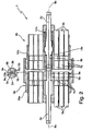
- hybrid optical connector 1 From the hybrid connector of the Fig. 1 is different in the Fig. 2 shown hybrid optical connector 1 only by the fact that here at least one, preferably both ferrules 5a, 5b protrude beyond their respective fiber end 9a, 9b, that the ferrule 5a has no co-operating with the centering 6a stop and that with completely nested plugs 4a, 4b, the two ferrules 5a, 5b bear with the Ferrulenenden frontally together. Due to the return of the at least one fiber end are the Fiber ends 9a, 9b not at each other, but it also remains an air gap 15th
- Fig. 3 shows a cross section of a hybrid cable 20 to which the plug 4a, 4b can be attached.
- the hybrid cable 20 has an optical waveguide cable 21 with an optical fiber 22 and integrated safety devices which prevents laser power output when radiation emerges from the guide region of the fiber or if the connector 1 is not formed properly, and several cables 23 each having one or more electrical cables Lines (Adem) 24 on.
- Fig. 4 schematically shows the structure of a laser system 30 with a laser head 31, in which optical components of a laser beam source 32 and, for example, an electrically controlled scanner 33 for deflecting an emerging from the laser head 31 laser beam 34 are arranged, and with a separate supply unit 35, in which a Pumplichtán 36 for the laser beam source 32 and a supply and control electronics 37 are arranged for the laser head 31.
- the laser beam source 32 is, for example, a diode-pumped solid-state laser (eg Nd: YAG or Nd: YVO 4 ), its optical components, such as a laser resonator with Auskoppelapt, rearview mirror and disposed therebetween laser crystal, and possibly a Q-switch, a jet trap and a beam shaping, in Laser head 31 are arranged.
- a diode-pumped solid-state laser eg Nd: YAG or Nd: YVO 4
- its optical components such as a laser resonator with Auskoppelspiegel, rearview mirror and disposed therebetween laser crystal, and possibly a Q-switch, a jet trap and a beam shaping, in Laser head 31 are arranged.
- the electrical and optical connection of the laser head 31 to the supply unit 35 takes place by means of the hybrid cable 20, which is plugged with its end provided plugs 4a in the provided on the laser head 31 and the supply unit 35 plug 4b.
- the high-power optical transmission path between the laser head 31 and the supply device 35 is constituted by an optical fiber 38 in the supply device 35 leading from the pump light source 36 to the connector 4b of the supply device 35 through the optical fiber 22 (see FIG. Fig. 3 ) in the hybrid cable 20 which optically connects the two plugs 4 a of the hybrid cable 20 with each other, and by an optical fiber 39 in the laser head 31, which leads from the plug 4 b of the laser head 31 to the laser beam source 32.
- the electrical connection between laser head 31 and supply unit 35 is formed by electrical lines 40 in the supply unit 35, which lead from the supply and control electronics 37 to the plug 4b of the supply device 35, by the electrical line 24 in the hybrid cable 20, which electrically connect the two plugs 4a of the hybrid cable 20 together, and by electrical lines 41 in the laser head 31, which lead from the plug 4b of the laser head 31, for example, to the scanner 33.
Landscapes
- Physics & Mathematics (AREA)
- General Physics & Mathematics (AREA)
- Optics & Photonics (AREA)
- Mechanical Coupling Of Light Guides (AREA)
- Optical Couplings Of Light Guides (AREA)
Description
- Die vorliegende Erfindung betrifft eine elektro-optische Hybrid-Steckverbindung gemäß Oberbegriff von Anspruch 1.
- Eine derartige elektro-optische Hybrid-Steckverbindung ist beispielsweise durch die
GB-A-2 346 269 - Longitudinal dioden-endgepumpte Festkörperlaser zeichnen sich durch einen hohen Wirkungsgrad und eine gute Strahlqualität aus. Die Fähigkeit, gleichzeitig verhältnismäßig große Energiemengen speichern zu können, ermöglicht die Erzeugung von Millijoule-Pulsen mit Pulsdauern von wenigen Nanosekunden mittels resonatorinterner Güteschalter. Dies privilegiert solche Laser für die Materialbearbeitung. Insbesondere bei der Laserbeschriftung ist eine ausgezeichnete Strahlqualität des Lasers unabdingbar, um ein präzises Bearbeitungsergebnis zu erhalten. Die Erzeugung eines stigmatischen Laserstrahls aus dem Festkörperlaser erfordert einen stigmatischen Pumpstrahl. Dieser wird in vielen Fällen erzeugt, indem das stark astigmatische und asymmetrische Strahlparameterprodukt eines Diodenlaserbarrens durch eine Strahlformungsoptik symmetrisiert und schließlich durch eine sphärische Fokussierungslinse in eine Multimodefaser eingekoppelt wird. Diese Faserkopplung ermöglicht grundsätzlich die räumliche Trennung zwischen der eigentlichen Festkörperlaserstrahlquelle, d.h. dem Festkörperlaserresonator, und der Pumplichtquelle. Diese räumliche Trennung von Festkörperlaserresonator und Pumplichtquelle ist insbesondere bei der Realisierung luftgekühlter Lasersysteme essentiell, um hochkompakte Laserköpfe, in denen sich der Festkörperlaserresonator befindet, mit geringem Gewicht zu bauen. Denn die Pumplichtquelle erzeugt eine derart hohe Wärmeleistung, dass großvolumige Kühlkörper mit hohem Gewicht verwendet werden müssen. Die Auslagerung der Pumplichtquelle samt der erforderlichen Kühleinheit in ein Versorgungsgerät des Festkörperlasers ermöglicht daher einen kleinvolumigen Aufbau des eigentlichen Laserkopfes.
- Die optische Verbindung zwischen dem Versorgungsgerät und dem Laserkopf ist durch die zuvor erwähnte Multimodefaser (Glasfaser) gebildet. In den meisten Fällen ist die Schnittstelle zwischen dem Versorgungsgerät und dem Laserkopf nicht allein durch die optische Pumplichtverbindung gegeben. Vielmehr werden auch elektrische Datenleitungen zur Steuerung von Aktuatoren im Laserkopf oder zur Übertragung von Sensordaten benötigt. Befindet sich am Laserkopf ein weiteres zu steuerndes Element (z.B. ein Spanner), so werden noch weitere elektrische Leitungen benötigt. Mit anderen Worten muss der Laserkopf sowohl optisch als auch elektrisch mit dem Versorgungsgerät verbunden werden. Um einen einfachen Tausch von Versorgungsgerät und Laserkopf beim Kunden vornehmen zu können, ist daher eine gemeinsame elektro-optische Hybridsteckverbindung für die mindestens eine optische Faser und die mindestens eine elektrische Leitung wünschenswert.
- Elektro-optische Hybrid-Steckverbindungen werden bereits in der Avionik, im Telekommunikationsbereich, beim Militär und in der Raumfahrt eingesetzt. Bei den bisher verfügbaren Hybrid-Steckverbindungen handelt es sich bei der optischen Schnittstelle meist um eine single-mode-Faserübertragung mit verhältnismäßig kleinen optischen Leistungen von typischerweise 1-2 W und kleinen Faserkerndurchmessern von ca. 7...50 µm. Aufgrund der niedrigen Leistungen sind die bisher verwendeten Hybrid-Steckerverbindungen hinsichtlich ihrer Zerstörung durch potentielle Kopplungsverluste unkritisch. Die bei diesen Hybrid-Steckerverbindungen verwendete "Butt-Coupling"-Technologie mit gekrümmten, unbeschichteten Faserendflächen funktioniert in diesem niedrigen Leistungsbereich sehr gut, ist aber für optische Multimode-Hochleistungsverbindungen (Leistung ≥ 10 W) mit großen Faserkerndurchmessern von ca. 0.1...1.0 mm ungeeignet. Die im niedrigen Leistungsbereich von 1-2 W typischerweise auftretenden Kopplungsverluste von etwa 0.2 dB bei single-mode-Fasern bzw. Multimodefasern mit kleinen Kerndurchmessern können im optischen Hochleistungsbereich (Leistung ≥ 10 W) nicht toleriert werden.
- Optische Steckverbindungen für optische Fasern bzw. Lichtwellenleiter sind hinlänglich bekannt. Ein bekannter optischer Stecker ist der so genannte F-SMA-(auch SMA-)Stecker, der international standardisiert wurde. Bei diesem F-SMA-Stecker handelt es sich um einen Schraubstecker, bei dem die Faser in einer relativ langen metallischen Ferrule mit einem Stiftdurchmesser von 3,175 mm geführt wird, die an der Kontaktfläche plan geschliffen ist. Die Einfügedämpfung, die mit diesem Stecker erzielt wird, hängt von einer Vielzahl von Kriterien ab. So liegt beispielsweise die Dämpfung bei Lichtleitern mit größerem Kerndurchmesser deutlich unter der von Fasern kleinerer Durchmesser.
- Die eingangs genannte
GB-A-2 346 269 - Aus
DE 42 08 140 A1 ist ferner eine Drehkupplung für Lichtwellenleiter bekannt, wobei die Faserenden der optisch miteinander verbundenen Lichtwellenleiter jeweils eine verrundete Fase aufweisen bzw. selbst abgerundet sind. Die Kupplung besteht aus einer Hülse und einem Stift, der durch die Faser gebildet ist. Zum Schutz der Faserenden ist in der Verbindungsstelle ein Spalt zwischen den Faserenden vorgesehen, der zur Verringerung von Reflexionen mit einer Indexflüssigkeit gefüllt ist. - Weiterhin sind aus
DE 20 2005 005 362 U1 ein Kabel zur optischen Datenübertragung sowie eine entsprechende optische Steckverbindung bekannt, wobei sich an die Faserenden im Bereich der Steckverbindung Linsen anschließen. Zwischen den Linsen bleibt auch bei vollständig ineinander gesteckten Steckern der Steckverbindung ein axialer Spalt bestehen. Hierdurch wird die Übertragung axialer Kräfte auf die optischen Komponenten, die zu Beschädigungen führen könnten, vermieden. Die optischen Komponenten in Form der Linsen bündeln das von der optischen Faser kommende Licht, so dass der Spalt verlustfrei überwunden werden kann. - Schließlich sind aus
US 4,896,939 noch ein Kabel und eine optische Steckverbindung zur optischen Datenübertragung bekannt, wobei die optischen Fasern an ihren Enden bündig mit einem Ferrulenende geschliffen und dann mit einer ca. 6,35 µm dünnen Chrom-Schicht versehen werden. Durch diese Chrom-Schichten sind die Faserenden einerseits geschützt und andererseits in der Steckverbindung ca. 12,7 µm voneinander beabstandet. - Die Aufgabe der vorliegenden Erfindung besteht darin, eine elektro-optische Hybrid-Steckverbindung für hohe optische Leistungen, insbesondere im Multimode-Betrieb, von größer ca. 10 W bereitzustellen.
- Diese Aufgabe wird erfindungsgemäß gelöst durch eine elektro-optische Hybrid-Steckverbindung mit den Merkmalen von Anspruch 1.
- Bei der erfindungsgemäßen Hybrid-Steckverbindung sind die Faserenden plan ausgeführt und mit einer Antireflexionsschicht versehen sowie zum Schutz der Antireflexionsschichten voneinander beabstandet. Durch diese Ausgestaltung können Strahlungsverluste an der optischen Schnittstelle weitestgehend minimiert werden, so dass auch bei Hochleistungsapplikationen die Zerstörschwelle der eingesetzten Komponenten nicht überschritten wird.
- Vorzugsweise sind die optischen Fasern Multimodefasern und für hohe optische Leistungen von mindestens 10 W ausgelegt.
- Um eine Schädigung der zumindest einen elektrischen Leitung durch austretende Strahlung aus zumindest einer der optischen Faser zu verhindern, verfügen die optischen Fasern über eine integrierte Sicherheitsvorrichtung. Diese führt bei Austritt von Strahlung aus dem Führungsbereich der Faser zur Abschaltung des Lasers. Diese Sicherheitsvorrichtung beruht bevorzugt auf einer Detektion von Widerstandsänderungen. Ergänzend verfügt das Hybridkabel über eine elektrische Leitung zur Überprüfung der ordnungsgemäßen Positionierung des Stecker der Hybrid-Steckverbindung. Sind die Kontakte dieser elektrischen Leitung nicht gesteckt, so wird ebenfalls kein Laserstrahl freigegeben.
- Weitere Vorteile der Erfindung ergeben sich aus den Ansprüchen, der Beschreibung und der Zeichnung. Ebenso können die vorstehend genannten und die noch weiter aufgeführten Merkmale je für sich oder zu mehreren in beliebigen Kombinationen Verwendung finden. Die gezeigten und beschriebenen Ausführungsformen sind nicht als abschließende Aufzählung zu verstehen, sondern haben vielmehr beispielhaften Charakter für die Schilderung der Erfindung.
- Es zeigen:
- Fig. 1
- eine erste Ausführungsform der erfindungsgemäßen elektro-optischen Hybrid-Steckverbindung;
- Fig. 2
- eine zweite Ausführungsform der erfindungsgemäßen elektro-optischen Hybrid-Steckverbindung;
- Fig. 3
- eine Ausführungsform eines erfindungsgemäßen Hybridkabels; und
- Fig. 4
- schematisch den Aufbau eines Lasersystems mit einem Versorgungsgerät und einem Laserkopf, die beide miteinander optisch und elektrisch über das in
Fig. 3 gezeigte Hybridkabel und die inFig. 1 oderFig. 2 gezeigte Hybrid-Steckverbindung verbunden sind. - Die in
Fig. 1 gezeigte elektro-optische Hybrid-Steckverbindung 1 dient zur optischen Verbindung mindestens einer ersten und einer zweiten optischen Faser (Lichtwellenleiter) 2a, 2b und zur elektrischen Verbindung mehrerer erster und zweiter elektrischer Leitungen 3a, 3b mithilfe zweier ineinandersteckbarer Stecker 4a, 4b. Die Komponenten des ersten Steckers 4a sind jeweils mit "a" und die Komponenten des zweiten Steckers 4b jeweils mit "b" gekennzeichnet. Der erste Stecker 4a weist eine Ferrule 5a, in der die erste optische Faser 2a eingefasst ist, eine die Ferrule 5a umgebende Zentrierhülse 6a aus Edelstahl oder Aluminium, die über die Ferrule 5a vorsteht, und mehrere an die ersten elektrischen Leitungen 3a angeschlossene elektrische Steckerkontakte 7a auf. Der zweite Stecker 4b weist eine Ferrule 5b, in der die zweite optische Faser 2b eingefasst ist, und mehrere an die zweiten elektrischen Leitungen 3b angeschlossene elektrische Steckerkontakte 7b auf. Die beiden optische Fasern 2a, 2b weisen jeweils rechtwinklig zur Faserachse 8a, 8b verlaufende plane Faserenden 9a, 9b auf, die jeweils bündig mit den Ferrulenenden abschließen. Die optischen Fasern 2a, 2b sind vorzugsweise Multimodefasern mit Faserkemdurchmessem von mindestens ca. 0.1 mm und für hohe optische Leistungen von mindestens ca.10 W ausgelegt. - Während die Ferrule 5a fest im Steckergehäuse 10a des ersten Steckers 4a montiert ist, ist die Ferrule 5b im Steckergehäuse 10b des zweiten Steckers 4b axial verschiebbar geführt und durch eine Feder 11b in Richtung auf die Steckerschnittstelle, also in
Fig.1 nach links, vorgespannt. Die Ferrule 5a ist durch die Zentrierhülse 6a nach außen abgeschirmt, und die Ferrule 5b ist von einer hier als Metallhülse 12b ausgebildeten metallischen Abschirmung umgeben. Die planen Faserenden 9a, 9b der beiden optischen Fasern 2a, 2b sind mit einer dielektrischen Antireflexionsschicht 13a, 13b versehen. - Bei vollständig ineinander gesteckten Steckern 4a, 4b ist, wie in
Fig. 1 gezeigt, die Ferrule 5b des zweiten Steckers 4b in die Zentrierhülse 6a des ersten Steckers 4a so weit eingesteckt, bis sie mit einem hier als Ringabsatz ausgebildeten Anschlag 14b stimseitig an der Zentrierhülse 6a anliegt und zwischen den beiden Ferrulen 5a, 5b sowie den Faserenden 9a, 9b ein vorbestimmter Luftspalt 15 von ca. 5-500 µm für typische Faserkemdurchmesser von 100-800 µm bei gleicher NA verbleibt. Dieser Luftspalt 15 verhindert den mechanischen Kontakt der Faserenden 9a, 9b und eine Beschädigung ihrer Antireflexionsschichten 13a, 13b. Durch die Feder 11 b ist die Ferrule 5b des zweiten Steckers 4b in Anlage an der Zentrierhülse 6 gehalten. Bei vollständig ineinander gesteckten Steckern 4a, 4b ist außerdem die Zentrierhülse 6a ihrerseits in die Metallhülse 12b eingesteckt und sind auch die Steckerkontakte 7a, 7b der beiden Stecker 4a, 4b elektrisch leitend ineinander gesteckt. Durch diese Hybridsteckverbindung 1 sind Strahlungsverluste an der optischen Schnittstelle weitestgehend minimiert, so dass auch bei Hochleistungsapplikationen die Zerstörschwelle der eingesetzten Komponenten nicht überschritten wird. - Von der Hybrid-Steckverbindung der
Fig. 1 unterscheidet sich die inFig. 2 gezeigte elektro-optische Hybrid-Steckverbindung 1 lediglich dadurch, dass hier zumindest eine, vorzugsweise beide Ferrulen 5a, 5b über ihr jeweiliges Faserende 9a, 9b vorstehen, dass die Ferrule 5a keinen mit der Zentrierhülse 6a zusammenwirkenden Anschlag aufweist und dass bei vollständig ineinander gesteckten Steckern 4a, 4b die beiden Ferrulen 5a, 5b mit den Ferrulenenden stirnseitig aneinander anliegen. Aufgrund der Rückversetzung des zumindest einen Faserendes liegen die Faserenden 9a, 9b nicht aneinander an, sondern es verbleibt auch hier ein Luftspalt 15. -
Fig. 3 zeigt einen Querschnitt eines Hybridkabels 20, an dem die Stecker 4a, 4b angebracht werden können. Im gezeigten Ausführungsbeispiel weist das Hybridkabel 20 ein Lichtwellenleiterkabel 21 mit einer optischen Faser 22 und integrierten Sicherheitsvorrichtungen, die bei Austritt von Strahlung aus dem Führungsbereich der Faser oder bei nicht ordnungsgemäß ausgebildeter Steckverbindung 1 eine Laserleistungsabgabe verhindert, sowie mehrere Kabel 23 mit jeweils einer oder mehreren elektrischen Leitungen (Adem) 24 auf. -
Fig. 4 zeigt schematisch den Aufbau eines Lasersystems 30 mit einem Laserkopf 31, in dem optische Komponenten einer Laserstrahlquelle 32 und z.B, ein elektrisch angesteuerter Scanner 33 zum Ablenken eines aus dem Laserkopf 31 austretenden Laserstrahls 34 angeordnet sind, und mit einem separaten Versorgungsgerät 35, In dem eine Pumplichtquelle 36 für die Laserstrahlquelle 32 und eine Versorgungs- und Ansteuerungselektronik 37 für den Laserkopf 31 angeordnet sind. Die Laserstrahlquelle 32 ist beispielsweise ein diodengepumpter Festkörperlaser (z.B. Nd:YAG oder Nd:YVO4), dessen optische Komponenten, wie z.B. ein Laserresonator mit Auskoppelspiegel, Rückspiegel und dazwischen angeordnetem Laserkistall, sowie ggf. ein Güteschalter, eine Strahlfalle und eine Strahlformung, im Laserkopf 31 angeordnet sind. - Die elektrische und optische Verbindung des Laserkopfes 31 mit dem Versorgungsgerät 35 erfolgt mithilfe des Hybridkabels 20, das mit seinen endseitig vorgesehenen Steckern 4a in die am Laserkopf 31 und am Versorgungsgerät 35 vorgesehenen Stecker 4b eingesteckt ist. Die optische Hochleistungsübertragungsstrecke zwischen Laserkopf 31 und Versorgungsgerät 35 ist gebildet durch eine optische Faser 38 im Versorgungsgerät 35, die von der Pumplichtquelle 36 zum Stecker 4b des Versorgungsgeräts 35 führt, durch die optische Faser 22 (vgl.
Fig. 3 ) im Hybridkabel 20, die die beiden Stecker 4a des Hybridkabels 20 miteinander optisch verbindet, und durch eine optische Faser 39 im Laserkopf 31, die vom Stecker 4b des Laserkopfes 31 zur Laserstrahlquelle 32 führt. Die elektrische Verbindung zwischen Laserkopf 31 und Versorgungsgerät 35 ist gebildet durch elektrische Leitungen 40 im Versorgungsgerät 35, die von der Versorgungs- und Ansteuerungselektronik 37 zum Stecker 4b des Versorgungsgeräts 35 führen, durch die elektrischen Leitung 24 im Hybridkabel 20, die die beiden Stecker 4a des Hybridkabels 20 miteinander elektrisch verbinden, und durch elektrische Leitungen 41 im Laserkopf 31, die vom Stecker 4b des Laserkopfes 31 z.B. zum Scanner 33 führen.
Claims (11)
- Elektro-optische Hybrid-Steckverbindung (1) zur optischen Verbindung mindestens einer ersten und einer zweiten optischen Faser (2a, 2b) und zur elektrischen Verbindung mindestens einer ersten und einer zweiten elektrischen Leitung (3a, 3b), umfassend:einen ersten Stecker (4a) mit der ersten optischen Faser (2a) und mit mindestens einem an die erste elektrische Leitung (3a) angeschlossenen elektrischen Steckerkontakt (7a),- einen zweiten Stecker (4b) mit der zweiten optischen Faser (2b) und mit mindestens einem an die zweite elektrische Leitung (3b) angeschlossenen elektrischen Steckerkontakt (7b),wobei jede der beiden optischen Fasern (2a, 2b) ein rechtwinklig zur Faserachse (8a, 8b) verlaufendes planes Faserende (9a, 9b) aufweist, und
wobei im zusammengesteckten Zustand der beiden Stecker (4a, 4b) die Steckerkontakte (7a, 7b) der beiden Stecker (4a, 4b) elektrisch leitend ineinander gesteckt sind und die Faserenden (9a, 9b) der beiden optischen Fasern (2a, 2b) durch einen Luftspalt (15) voneinander beabstandet sind,
dadurch gekennzeichnet,
dass die optischen Fasern (2a, 2b) zur Übertragung von hohen optischen Leistungen von mindestens 10 Watt ausgelegt sind,
dass die erste optische Faser (2a) in einer Ferrule (5a) eingefasst ist, die im ersten Stecker (4a) angeordnet und von einer über die Ferrule (5a) vorstehenden Zentrierhülse (6a) umgeben ist,
dass die zweite optische Faser (2b) in einer Ferrule (5b) eingefasst ist, die im zweiten Stecker (4b) angeordnet ist,
dass das plane Faserende (9a, 9b) jeder der beiden optischen Fasern (2a, 2b) mit einer Antireflexionsschicht (13a, 13b) versehen ist, und
dass im zusammengesteckten Zustand der beiden Stecker (4a, 4b) die Ferrule (5b) des zweiten Steckers (4b) in die Zentrierhülse (6a) des ersten Steckers (4a) bis zur Anlage an der Zentrierhülse (6a) oder an der Ferrule (5a) des ersten Steckers (4a) eingesteckt ist. - Hybrid-Steckverbindung nach Anspruch 1, dadurch gekennzeichnet, dass zumindest eine, insbesondere jede der beiden Ferrulen (5a, 5b) bündig mit dem Faserende (9a, 9b) der jeweils eingefassten Faser (2a, 2b) abschließt.
- Hybrid-Steckverbindung nach Anspruch 1 oder 2, dadurch gekennzeichnet, dass zumindest eine, insbesondere jede der beiden Ferrulen (5a, 5b) über das Faserende (9a, 9b) der jeweils eingefassten Faser (2a, 2b) vorsteht.
- Hybrid-Steckverbindung nach einem der vorhergehenden Ansprüche, dadurch gekennzeichnet, dass die Ferrule (5b) des zweiten Steckers (2b) einen Anschlag (14b) aufweist, mit dem sie im zusammengesteckten Zustand der beiden Stecker (4a, 4b) an der Zentrierhülse (6a) des ersten Steckers (2a) anliegt.
- Hybrid-Steckverbindung nach einem der Ansprüche 1 bis 3, dadurch gekennzeichnet, dass zumindest eine, insbesondere jede der beiden Ferrulen (5a, 5b) über das Faserende (9a, 9b) der jeweils eingefassten Faser (2a, 2b) vorsteht und dass im zusammengesteckten Zustand der beiden Stecker (4a, 4b) die beiden Ferrulen (5a, 5b) mit ihren vorstehenden Ferrulenenden stirnseitig aneinander anliegen.
- Hybrid-Steckverbindung nach einem der vorhergehenden Ansprüche, dadurch gekennzeichnet, dass die Ferrule (5a, 5b) oder die Hülse (6a, 12b) mindestens eines der beiden Stecker (4a, 4b) gegen die Wirkung einer Feder (11a) axial verschiebbar geführt ist.
- Hybrid-Steckverbindung nach einem der vorhergehenden Ansprüche, dadurch gekennzeichnet, dass jeder der beiden Stecker (4a, 4b) eine die Ferrule (5a, 5b) umgebende metallische Abschirmung, insbesondere eine Metallhülse (6a, 12b), aufweist.
- Hybrid-Steckverbindung nach einem der vorhergehenden Ansprüche, dadurch gekennzeichnet, dass die Hülse (6a, 12b) aus Metall, insbesondere aus Edelstahl oder Messing ist.
- Hybrid-Steckverbindung nach einem der vorhergehenden Ansprüche, dadurch gekennzeichnet, dass die optischen Fasern (2a, 2b) Multimodefasern sind.
- Hybrid-Steckverbindung nach einem der vorhergehenden Ansprüche, dadurch gekennzeichnet, dass die optischen Fasern (2a, 2b) für hohe optische Leistungen von mindestens 10 W ausgelegt sind.
- Hybrid-Steckverbindung nach einem der vorhergehenden Ansprüche, dadurch gekennzeichnet, dass mindestens einer der beiden Stecker (4a, 4b) an einem Hybridkabel (20) vorgesehen ist, das mindestens eine optische Faser (22) und mindestens eine elektrische Leitung (24) aufweist.
Priority Applications (4)
| Application Number | Priority Date | Filing Date | Title |
|---|---|---|---|
| EP07011761A EP2003477B1 (de) | 2007-06-15 | 2007-06-15 | Elektro-optische Hybrid-Steckverbindung zur Übertragung von hohen optischen Leistungen und elektrischen Signalen |
| CN200810109480XA CN101324688B (zh) | 2007-06-15 | 2008-06-12 | 用于传输高光学功率和电信号的光电混合连接装置 |
| US12/138,809 US7677813B2 (en) | 2007-06-15 | 2008-06-13 | Electro-optical hybrid connection assembly |
| JP2008155204A JP2008310330A (ja) | 2007-06-15 | 2008-06-13 | 高い光学的な出力と電気的な信号とを伝送するために電気光学的なハイブリッド差込み接続装置 |
Applications Claiming Priority (1)
| Application Number | Priority Date | Filing Date | Title |
|---|---|---|---|
| EP07011761A EP2003477B1 (de) | 2007-06-15 | 2007-06-15 | Elektro-optische Hybrid-Steckverbindung zur Übertragung von hohen optischen Leistungen und elektrischen Signalen |
Publications (2)
| Publication Number | Publication Date |
|---|---|
| EP2003477A1 EP2003477A1 (de) | 2008-12-17 |
| EP2003477B1 true EP2003477B1 (de) | 2012-05-23 |
Family
ID=38531744
Family Applications (1)
| Application Number | Title | Priority Date | Filing Date |
|---|---|---|---|
| EP07011761A Not-in-force EP2003477B1 (de) | 2007-06-15 | 2007-06-15 | Elektro-optische Hybrid-Steckverbindung zur Übertragung von hohen optischen Leistungen und elektrischen Signalen |
Country Status (4)
| Country | Link |
|---|---|
| US (1) | US7677813B2 (de) |
| EP (1) | EP2003477B1 (de) |
| JP (1) | JP2008310330A (de) |
| CN (1) | CN101324688B (de) |
Families Citing this family (33)
| Publication number | Priority date | Publication date | Assignee | Title |
|---|---|---|---|---|
| US8407367B2 (en) * | 2007-12-26 | 2013-03-26 | Intel Corporation | Unified connector architecture |
| US8700821B2 (en) | 2008-08-22 | 2014-04-15 | Intel Corporation | Unified multi-transport medium connector architecture |
| CA2841694C (en) * | 2009-02-05 | 2019-08-20 | Japan Aviation Electronics Industry, Limited | Optical connector apparatus |
| JP5233780B2 (ja) * | 2009-03-24 | 2013-07-10 | 大日本印刷株式会社 | 給電器、受電器、非接触型データ及び電力伝送装置 |
| JP2011033849A (ja) * | 2009-08-03 | 2011-02-17 | Yazaki Corp | 中継光コネクタ |
| WO2011097473A2 (en) | 2010-02-04 | 2011-08-11 | Adc Telecommunications, Inc. | Ruggedized fiber optic/electrical connection system |
| JP2013522688A (ja) * | 2010-03-19 | 2013-06-13 | コーニング インコーポレイテッド | 電子装置用光ファイバインタフェース装置 |
| JP5400744B2 (ja) * | 2010-10-19 | 2014-01-29 | 古河電気工業株式会社 | 光ファイバ端子、端子付光ファイバケーブル、光コネクタ、コネクタ付光ファイバケーブル |
| EP2540434A1 (de) | 2011-06-28 | 2013-01-02 | Trumpf Laser Marking Systems AG | Lasersystem mit einem elektrooptischen Anschlusselement |
| CN103842870A (zh) * | 2011-08-31 | 2014-06-04 | 惠普发展公司,有限责任合伙企业 | 用于可调制的源的多模光纤 |
| US8953644B2 (en) | 2011-12-27 | 2015-02-10 | Intel Corporation | Multi-protocol I/O interconnect time synchronization |
| US8775713B2 (en) | 2011-12-27 | 2014-07-08 | Intel Corporation | Multi-protocol tunneling over an I/O interconnect |
| US8856420B2 (en) | 2011-12-27 | 2014-10-07 | Intel Corporation | Multi-protocol I/O interconnect flow control |
| US9697159B2 (en) | 2011-12-27 | 2017-07-04 | Intel Corporation | Multi-protocol I/O interconnect time synchronization |
| US9565132B2 (en) | 2011-12-27 | 2017-02-07 | Intel Corporation | Multi-protocol I/O interconnect including a switching fabric |
| US9252970B2 (en) | 2011-12-27 | 2016-02-02 | Intel Corporation | Multi-protocol I/O interconnect architecture |
| US8782321B2 (en) | 2012-02-08 | 2014-07-15 | Intel Corporation | PCI express tunneling over a multi-protocol I/O interconnect |
| US8880923B2 (en) | 2012-03-29 | 2014-11-04 | Intel Corporation | Link power management in an I/O interconnect |
| JP5969840B2 (ja) * | 2012-06-29 | 2016-08-17 | オリンパス株式会社 | 光電気複合コネクタ |
| EP2762938B1 (de) * | 2013-02-01 | 2020-07-15 | Corning Optical Communications LLC | Kabelanordnung mit elektrischen Leitern und faseroptische Datenleitungen und einer abgeschirmten Aufteilstelle |
| US9784937B2 (en) | 2013-02-01 | 2017-10-10 | Ccs Technology, Inc. | Cable assembly having electrical power conductors and fiber optic data lines |
| WO2014186436A1 (en) * | 2013-05-16 | 2014-11-20 | Corning Optical Communications LLC | Optical plug having a removable and replaceable nosepiece and a complimentary receptacle |
| US9804342B2 (en) * | 2015-03-25 | 2017-10-31 | Foxconn Interconnect Technology Limited | Hybrid connector for both electrical and optical transmission |
| CN105552678B (zh) * | 2016-02-25 | 2018-08-10 | 广东金力变速科技股份有限公司 | 一种激光头供电装置 |
| US10113739B2 (en) | 2017-01-06 | 2018-10-30 | Delta Faucet Company | Connector for an electronic faucet |
| US10505323B2 (en) | 2018-01-19 | 2019-12-10 | Te Connectivity Corporation | Communication system having coaxial connector assembly |
| US10505322B2 (en) | 2018-01-19 | 2019-12-10 | Te Connectivity Corporation | Communication system having coaxial connector assembly |
| US10558000B2 (en) * | 2018-01-22 | 2020-02-11 | Te Connectivity Corporation | Communication system having coaxial connector module and fiber optic module |
| US10498061B1 (en) | 2018-12-17 | 2019-12-03 | Te Connectivity Corporation | Coaxial connector assembly |
| US11333835B2 (en) * | 2019-07-08 | 2022-05-17 | Arrayed Fiberoptics Corporation | Microfabrication method for optical components |
| CN110441868B (zh) * | 2019-07-31 | 2020-12-25 | 尚华 | 一种光纤导丝、阵列磁性光纤连接器及其使用方法 |
| US11025006B2 (en) | 2019-09-04 | 2021-06-01 | Te Connectivity Corporation | Communication system having connector assembly |
| US20250334762A1 (en) * | 2024-04-24 | 2025-10-30 | Zynex Monitoring Solutions, Inc | Electro-Optical Photoplethysmographic Connector |
Citations (2)
| Publication number | Priority date | Publication date | Assignee | Title |
|---|---|---|---|---|
| WO1998019191A1 (en) * | 1996-10-30 | 1998-05-07 | The Government Of The United States Of America As Represented By The Secretary Of The Navy | Optical fiber terminations |
| WO2003005088A1 (en) * | 2001-07-05 | 2003-01-16 | Corning Incorporated | High power expanded beam connector and methods for using and making the high power expanded beam connector |
Family Cites Families (21)
| Publication number | Priority date | Publication date | Assignee | Title |
|---|---|---|---|---|
| US4279469A (en) * | 1975-05-27 | 1981-07-21 | The United States Of America As Represented By The Secretary Of The Navy | Separable fiber optic cable connector |
| US4707063A (en) * | 1984-02-02 | 1987-11-17 | Polaroid Corporation | Widely spaced fiber optic connector and multiplexer/demultiplexer using same |
| US4744629A (en) * | 1985-08-16 | 1988-05-17 | Augat Inc. | Multifiber optical cable connector |
| JPS6271604A (ja) * | 1985-09-26 | 1987-04-02 | 住友ベークライト株式会社 | 合板の製造方法 |
| US4896939A (en) | 1987-10-30 | 1990-01-30 | D. G. O'brien, Inc. | Hybrid fiber optic/electrical cable and connector |
| JP2504852B2 (ja) * | 1990-03-02 | 1996-06-05 | 日本電信電話株式会社 | 光コネクタプラグ |
| JPH0534530A (ja) * | 1991-07-29 | 1993-02-12 | Furukawa Electric Co Ltd:The | 異種光フアイバの接続構造 |
| DE4208140C2 (de) | 1992-03-13 | 1995-02-09 | Rosenberger Hochfrequenztech | Drehkupplung für Lichtwellenleiter |
| US5448676A (en) * | 1993-06-21 | 1995-09-05 | Mcdonnell Douglas Corporation | Electro-optical contact coupling |
| US6065882A (en) * | 1995-07-14 | 2000-05-23 | Cogent Light Technologies, Inc. | Snap-in proximal connector for mounting an optic fiber element into a light source system |
| JP3092520B2 (ja) * | 1996-08-01 | 2000-09-25 | 岩崎通信機株式会社 | 高周波無線用防爆コネクタ |
| US6062739A (en) * | 1997-07-25 | 2000-05-16 | Raytheon Company | Fiber optic connector |
| DE19810561A1 (de) * | 1998-03-11 | 1999-09-16 | Siemens Ag | Hybrider Datenstecker |
| GB2346269A (en) | 1999-01-27 | 2000-08-02 | Rover Group | A transmission line interconnection module |
| JP4508444B2 (ja) * | 2001-02-22 | 2010-07-21 | 日本モレックス株式会社 | 光ファイバ用コネクタ |
| JP2002323641A (ja) * | 2001-04-25 | 2002-11-08 | Ms Giken:Kk | 光ファイバ用コネクタ |
| JP3921571B2 (ja) * | 2001-11-21 | 2007-05-30 | モレックス インコーポレーテッド | 複合コネクタ装置 |
| JP2006039275A (ja) * | 2004-07-28 | 2006-02-09 | Kyocera Corp | 光通信用割スリーブ及びその製造方法 |
| DE202005005362U1 (de) | 2005-04-05 | 2005-06-02 | Rosenberger Hochfrequenztechnik Gmbh & Co. Kg | Datenübertragungskabel mit FAKRA-Gehäuse |
| US7572063B2 (en) * | 2005-09-12 | 2009-08-11 | Stratos International, Inc. | Opto-electric connector |
| JP4540583B2 (ja) * | 2005-10-17 | 2010-09-08 | 矢崎総業株式会社 | 光ファイバケーブルとフェルールの固定構造 |
-
2007
- 2007-06-15 EP EP07011761A patent/EP2003477B1/de not_active Not-in-force
-
2008
- 2008-06-12 CN CN200810109480XA patent/CN101324688B/zh not_active Expired - Fee Related
- 2008-06-13 US US12/138,809 patent/US7677813B2/en not_active Expired - Fee Related
- 2008-06-13 JP JP2008155204A patent/JP2008310330A/ja active Pending
Patent Citations (2)
| Publication number | Priority date | Publication date | Assignee | Title |
|---|---|---|---|---|
| WO1998019191A1 (en) * | 1996-10-30 | 1998-05-07 | The Government Of The United States Of America As Represented By The Secretary Of The Navy | Optical fiber terminations |
| WO2003005088A1 (en) * | 2001-07-05 | 2003-01-16 | Corning Incorporated | High power expanded beam connector and methods for using and making the high power expanded beam connector |
Also Published As
| Publication number | Publication date |
|---|---|
| US20090028495A1 (en) | 2009-01-29 |
| US7677813B2 (en) | 2010-03-16 |
| CN101324688A (zh) | 2008-12-17 |
| EP2003477A1 (de) | 2008-12-17 |
| JP2008310330A (ja) | 2008-12-25 |
| CN101324688B (zh) | 2010-12-15 |
Similar Documents
| Publication | Publication Date | Title |
|---|---|---|
| EP2003477A1 (de) | Elektro-optische Hybrid-Steckverbindung zur Übertragung von hohen optischen Leistungen und elektrischen Signalen | |
| EP2962142B1 (de) | Optisches modul für modular aufgebaute industriesteckverbinder | |
| DE112004002202B4 (de) | Lichtleitfaser-Pumpmultiplexer | |
| WO2009030360A1 (de) | Faseroptischer steckverbinder mit einer strahlaufweitungsvorrichtung | |
| WO2013064481A1 (de) | Optische transportfaser und verfahren zu deren herstellung | |
| DE19702146A1 (de) | Festkörperlasereinrichtung, die durch von einer Laserdiode ausgesendetes Licht gepumpt wird | |
| DD298165A5 (de) | Lichtwellenleitersteckverbindung | |
| DE102009009367B4 (de) | Lichtleiter zur Übertragung von Strahlung sowie Herstellverfahren | |
| DE102012202177B3 (de) | Freistrahloptische Faser-zu-Faser-Kopplungsvorrichtung | |
| DE10201127C2 (de) | Anordnung zum Ein- und/oder Auskoppeln optischer Signale mindestens eines optischen Datenkanals in bzw. aus einem Lichtwellenleiter | |
| EP4291825A1 (de) | Hohlkernfaser zur übertragung von laserlicht | |
| EP0416640A2 (de) | Verfahren zur Herstellung eines optischen Verschmelzkopplers und danach hergestellter Koppler | |
| DE102023118609B4 (de) | Multilichtwellenleiterstecker sowie Lichtwellenleiterverbinder mit einem solchen | |
| DE60005180T2 (de) | Verfahren zur massenherstellung von mikrolinsen am ende einer gruppe von optischen fasern von der art eines faserbandes | |
| WO2000014582A2 (de) | Abschlussstück für lichtleitfasern | |
| DE102015205163B4 (de) | Optisches System für eine Laserbearbeitungsmaschine, mit einem optischen Element in einem Stecker eines Lichtleitkabels | |
| DE19927167A1 (de) | Koppelelement zur Kopplung hochintensiver Lichtstrahlung und Verfahren zu dessen Herstellung sowie Anordnung aus Koppelelementen zur Kopplung hochintensiver Lichtstrahlung | |
| DE4133220C2 (de) | Fasern-Linsen-Anordnung zum optischen Koppeln | |
| DE19931944B4 (de) | Umlenkende Auskopplung in einer Leiterplatte eingebetteter Lichtleiter | |
| EP4500646B1 (de) | Optische anordnung mit faserlaser oder faserverstärker und freistrahl-koppelelement | |
| EP2018583B1 (de) | Steckverbinder mit vorrichtung zur kompensation von längenausdehnungen eines lichtwellenleiters | |
| DE29816108U1 (de) | Abschlußstück für Lichtleitfasern | |
| DE202015101457U1 (de) | Optisches System für eine Laserbearbeitungsmaschine, mit einem optischen Element in einem Stecker eines Lichtleitkabels | |
| DE102023118608B4 (de) | Rückreflexionsverminderter Lichtwellenleiterstecker sowie Lichtwellenleiterverbinder mit einem solchen | |
| EP1482337A1 (de) | Lichtleitersteckeranordnung und Herstellungsverfahren dafür |
Legal Events
| Date | Code | Title | Description |
|---|---|---|---|
| PUAI | Public reference made under article 153(3) epc to a published international application that has entered the european phase |
Free format text: ORIGINAL CODE: 0009012 |
|
| 17P | Request for examination filed |
Effective date: 20080212 |
|
| AK | Designated contracting states |
Kind code of ref document: A1 Designated state(s): AT BE BG CH CY CZ DE DK EE ES FI FR GB GR HU IE IS IT LI LT LU LV MC MT NL PL PT RO SE SI SK TR |
|
| AX | Request for extension of the european patent |
Extension state: AL BA HR MK RS |
|
| AKX | Designation fees paid |
Designated state(s): AT BE BG CH CY CZ DE DK EE ES FI FR GB GR HU IE IS IT LI LT LU LV MC MT NL PL PT RO SE SI SK TR |
|
| GRAP | Despatch of communication of intention to grant a patent |
Free format text: ORIGINAL CODE: EPIDOSNIGR1 |
|
| GRAS | Grant fee paid |
Free format text: ORIGINAL CODE: EPIDOSNIGR3 |
|
| GRAA | (expected) grant |
Free format text: ORIGINAL CODE: 0009210 |
|
| AK | Designated contracting states |
Kind code of ref document: B1 Designated state(s): AT BE BG CH CY CZ DE DK EE ES FI FR GB GR HU IE IS IT LI LT LU LV MC MT NL PL PT RO SE SI SK TR |
|
| REG | Reference to a national code |
Ref country code: GB Ref legal event code: FG4D Free format text: NOT ENGLISH |
|
| REG | Reference to a national code |
Ref country code: CH Ref legal event code: EP |
|
| REG | Reference to a national code |
Ref country code: AT Ref legal event code: REF Ref document number: 559329 Country of ref document: AT Kind code of ref document: T Effective date: 20120615 |
|
| REG | Reference to a national code |
Ref country code: IE Ref legal event code: FG4D Free format text: LANGUAGE OF EP DOCUMENT: GERMAN |
|
| REG | Reference to a national code |
Ref country code: DE Ref legal event code: R096 Ref document number: 502007009898 Country of ref document: DE Effective date: 20120726 |
|
| REG | Reference to a national code |
Ref country code: NL Ref legal event code: VDEP Effective date: 20120523 |
|
| REG | Reference to a national code |
Ref country code: LT Ref legal event code: MG4D Effective date: 20120523 |
|
| PG25 | Lapsed in a contracting state [announced via postgrant information from national office to epo] |
Ref country code: IS Free format text: LAPSE BECAUSE OF FAILURE TO SUBMIT A TRANSLATION OF THE DESCRIPTION OR TO PAY THE FEE WITHIN THE PRESCRIBED TIME-LIMIT Effective date: 20120923 Ref country code: CY Free format text: LAPSE BECAUSE OF FAILURE TO SUBMIT A TRANSLATION OF THE DESCRIPTION OR TO PAY THE FEE WITHIN THE PRESCRIBED TIME-LIMIT Effective date: 20120523 Ref country code: SE Free format text: LAPSE BECAUSE OF FAILURE TO SUBMIT A TRANSLATION OF THE DESCRIPTION OR TO PAY THE FEE WITHIN THE PRESCRIBED TIME-LIMIT Effective date: 20120523 Ref country code: FI Free format text: LAPSE BECAUSE OF FAILURE TO SUBMIT A TRANSLATION OF THE DESCRIPTION OR TO PAY THE FEE WITHIN THE PRESCRIBED TIME-LIMIT Effective date: 20120523 Ref country code: LT Free format text: LAPSE BECAUSE OF FAILURE TO SUBMIT A TRANSLATION OF THE DESCRIPTION OR TO PAY THE FEE WITHIN THE PRESCRIBED TIME-LIMIT Effective date: 20120523 |
|
| PG25 | Lapsed in a contracting state [announced via postgrant information from national office to epo] |
Ref country code: LV Free format text: LAPSE BECAUSE OF FAILURE TO SUBMIT A TRANSLATION OF THE DESCRIPTION OR TO PAY THE FEE WITHIN THE PRESCRIBED TIME-LIMIT Effective date: 20120523 Ref country code: GR Free format text: LAPSE BECAUSE OF FAILURE TO SUBMIT A TRANSLATION OF THE DESCRIPTION OR TO PAY THE FEE WITHIN THE PRESCRIBED TIME-LIMIT Effective date: 20120824 Ref country code: PT Free format text: LAPSE BECAUSE OF FAILURE TO SUBMIT A TRANSLATION OF THE DESCRIPTION OR TO PAY THE FEE WITHIN THE PRESCRIBED TIME-LIMIT Effective date: 20120924 Ref country code: SI Free format text: LAPSE BECAUSE OF FAILURE TO SUBMIT A TRANSLATION OF THE DESCRIPTION OR TO PAY THE FEE WITHIN THE PRESCRIBED TIME-LIMIT Effective date: 20120523 |
|
| BERE | Be: lapsed |
Owner name: TRUMPF LASER MARKING SYSTEMS A.G. Effective date: 20120630 |
|
| PG25 | Lapsed in a contracting state [announced via postgrant information from national office to epo] |
Ref country code: EE Free format text: LAPSE BECAUSE OF FAILURE TO SUBMIT A TRANSLATION OF THE DESCRIPTION OR TO PAY THE FEE WITHIN THE PRESCRIBED TIME-LIMIT Effective date: 20120523 Ref country code: MC Free format text: LAPSE BECAUSE OF NON-PAYMENT OF DUE FEES Effective date: 20120630 Ref country code: NL Free format text: LAPSE BECAUSE OF FAILURE TO SUBMIT A TRANSLATION OF THE DESCRIPTION OR TO PAY THE FEE WITHIN THE PRESCRIBED TIME-LIMIT Effective date: 20120523 Ref country code: RO Free format text: LAPSE BECAUSE OF FAILURE TO SUBMIT A TRANSLATION OF THE DESCRIPTION OR TO PAY THE FEE WITHIN THE PRESCRIBED TIME-LIMIT Effective date: 20120523 Ref country code: DK Free format text: LAPSE BECAUSE OF FAILURE TO SUBMIT A TRANSLATION OF THE DESCRIPTION OR TO PAY THE FEE WITHIN THE PRESCRIBED TIME-LIMIT Effective date: 20120523 Ref country code: CZ Free format text: LAPSE BECAUSE OF FAILURE TO SUBMIT A TRANSLATION OF THE DESCRIPTION OR TO PAY THE FEE WITHIN THE PRESCRIBED TIME-LIMIT Effective date: 20120523 Ref country code: SK Free format text: LAPSE BECAUSE OF FAILURE TO SUBMIT A TRANSLATION OF THE DESCRIPTION OR TO PAY THE FEE WITHIN THE PRESCRIBED TIME-LIMIT Effective date: 20120523 |
|
| PG25 | Lapsed in a contracting state [announced via postgrant information from national office to epo] |
Ref country code: PL Free format text: LAPSE BECAUSE OF FAILURE TO SUBMIT A TRANSLATION OF THE DESCRIPTION OR TO PAY THE FEE WITHIN THE PRESCRIBED TIME-LIMIT Effective date: 20120523 |
|
| REG | Reference to a national code |
Ref country code: IE Ref legal event code: MM4A |
|
| PLBE | No opposition filed within time limit |
Free format text: ORIGINAL CODE: 0009261 |
|
| STAA | Information on the status of an ep patent application or granted ep patent |
Free format text: STATUS: NO OPPOSITION FILED WITHIN TIME LIMIT |
|
| PG25 | Lapsed in a contracting state [announced via postgrant information from national office to epo] |
Ref country code: ES Free format text: LAPSE BECAUSE OF FAILURE TO SUBMIT A TRANSLATION OF THE DESCRIPTION OR TO PAY THE FEE WITHIN THE PRESCRIBED TIME-LIMIT Effective date: 20120903 Ref country code: BE Free format text: LAPSE BECAUSE OF NON-PAYMENT OF DUE FEES Effective date: 20120630 Ref country code: IE Free format text: LAPSE BECAUSE OF NON-PAYMENT OF DUE FEES Effective date: 20120615 |
|
| 26N | No opposition filed |
Effective date: 20130226 |
|
| REG | Reference to a national code |
Ref country code: DE Ref legal event code: R097 Ref document number: 502007009898 Country of ref document: DE Effective date: 20130226 |
|
| PG25 | Lapsed in a contracting state [announced via postgrant information from national office to epo] |
Ref country code: BG Free format text: LAPSE BECAUSE OF FAILURE TO SUBMIT A TRANSLATION OF THE DESCRIPTION OR TO PAY THE FEE WITHIN THE PRESCRIBED TIME-LIMIT Effective date: 20120823 Ref country code: MT Free format text: LAPSE BECAUSE OF FAILURE TO SUBMIT A TRANSLATION OF THE DESCRIPTION OR TO PAY THE FEE WITHIN THE PRESCRIBED TIME-LIMIT Effective date: 20120523 |
|
| PG25 | Lapsed in a contracting state [announced via postgrant information from national office to epo] |
Ref country code: TR Free format text: LAPSE BECAUSE OF FAILURE TO SUBMIT A TRANSLATION OF THE DESCRIPTION OR TO PAY THE FEE WITHIN THE PRESCRIBED TIME-LIMIT Effective date: 20120523 |
|
| PG25 | Lapsed in a contracting state [announced via postgrant information from national office to epo] |
Ref country code: LU Free format text: LAPSE BECAUSE OF NON-PAYMENT OF DUE FEES Effective date: 20120615 |
|
| PG25 | Lapsed in a contracting state [announced via postgrant information from national office to epo] |
Ref country code: HU Free format text: LAPSE BECAUSE OF FAILURE TO SUBMIT A TRANSLATION OF THE DESCRIPTION OR TO PAY THE FEE WITHIN THE PRESCRIBED TIME-LIMIT Effective date: 20070615 |
|
| REG | Reference to a national code |
Ref country code: FR Ref legal event code: PLFP Year of fee payment: 10 |
|
| REG | Reference to a national code |
Ref country code: FR Ref legal event code: PLFP Year of fee payment: 11 |
|
| REG | Reference to a national code |
Ref country code: DE Ref legal event code: R082 Ref document number: 502007009898 Country of ref document: DE Representative=s name: KOHLER SCHMID MOEBUS PATENTANWAELTE PARTNERSCH, DE Ref country code: DE Ref legal event code: R081 Ref document number: 502007009898 Country of ref document: DE Owner name: TRUMPF SCHWEIZ AG, CH Free format text: FORMER OWNER: TRUMPF LASER MARKING SYSTEMS AG, GRUESCH, CH |
|
| REG | Reference to a national code |
Ref country code: FR Ref legal event code: PLFP Year of fee payment: 12 |
|
| REG | Reference to a national code |
Ref country code: CH Ref legal event code: PFUS Owner name: TRUMPF SCHWEIZ AG, CH Free format text: FORMER OWNER: TRUMPF LASER MARKING SYSTEMS AG, CH |
|
| REG | Reference to a national code |
Ref country code: AT Ref legal event code: PC Ref document number: 559329 Country of ref document: AT Kind code of ref document: T Owner name: TRUMPF SCHWEIZ AG, CH Effective date: 20180626 |
|
| REG | Reference to a national code |
Ref country code: FR Ref legal event code: TP Owner name: TRUMPF SCHWEIZ AG, CH Effective date: 20181102 |
|
| REG | Reference to a national code |
Ref country code: GB Ref legal event code: 732E Free format text: REGISTERED BETWEEN 20190110 AND 20190116 |
|
| PGFP | Annual fee paid to national office [announced via postgrant information from national office to epo] |
Ref country code: DE Payment date: 20190619 Year of fee payment: 13 Ref country code: IT Payment date: 20190624 Year of fee payment: 13 |
|
| PGFP | Annual fee paid to national office [announced via postgrant information from national office to epo] |
Ref country code: FR Payment date: 20190619 Year of fee payment: 13 |
|
| PGFP | Annual fee paid to national office [announced via postgrant information from national office to epo] |
Ref country code: CH Payment date: 20190619 Year of fee payment: 13 |
|
| PGFP | Annual fee paid to national office [announced via postgrant information from national office to epo] |
Ref country code: GB Payment date: 20190619 Year of fee payment: 13 Ref country code: AT Payment date: 20190621 Year of fee payment: 13 |
|
| REG | Reference to a national code |
Ref country code: DE Ref legal event code: R119 Ref document number: 502007009898 Country of ref document: DE |
|
| REG | Reference to a national code |
Ref country code: CH Ref legal event code: PL |
|
| REG | Reference to a national code |
Ref country code: AT Ref legal event code: MM01 Ref document number: 559329 Country of ref document: AT Kind code of ref document: T Effective date: 20200615 |
|
| GBPC | Gb: european patent ceased through non-payment of renewal fee |
Effective date: 20200615 |
|
| PG25 | Lapsed in a contracting state [announced via postgrant information from national office to epo] |
Ref country code: CH Free format text: LAPSE BECAUSE OF NON-PAYMENT OF DUE FEES Effective date: 20200630 Ref country code: LI Free format text: LAPSE BECAUSE OF NON-PAYMENT OF DUE FEES Effective date: 20200630 Ref country code: GB Free format text: LAPSE BECAUSE OF NON-PAYMENT OF DUE FEES Effective date: 20200615 Ref country code: FR Free format text: LAPSE BECAUSE OF NON-PAYMENT OF DUE FEES Effective date: 20200630 |
|
| PG25 | Lapsed in a contracting state [announced via postgrant information from national office to epo] |
Ref country code: DE Free format text: LAPSE BECAUSE OF NON-PAYMENT OF DUE FEES Effective date: 20210101 Ref country code: AT Free format text: LAPSE BECAUSE OF NON-PAYMENT OF DUE FEES Effective date: 20200615 |
|
| PG25 | Lapsed in a contracting state [announced via postgrant information from national office to epo] |
Ref country code: IT Free format text: LAPSE BECAUSE OF NON-PAYMENT OF DUE FEES Effective date: 20200615 |