EP2003405A2 - Fixing device for flat components attachable to a framework, in particular for solar modules - Google Patents
Fixing device for flat components attachable to a framework, in particular for solar modules Download PDFInfo
- Publication number
- EP2003405A2 EP2003405A2 EP08007003A EP08007003A EP2003405A2 EP 2003405 A2 EP2003405 A2 EP 2003405A2 EP 08007003 A EP08007003 A EP 08007003A EP 08007003 A EP08007003 A EP 08007003A EP 2003405 A2 EP2003405 A2 EP 2003405A2
- Authority
- EP
- European Patent Office
- Prior art keywords
- profile
- component
- fastening device
- region
- holding
- Prior art date
- Legal status (The legal status is an assumption and is not a legal conclusion. Google has not performed a legal analysis and makes no representation as to the accuracy of the status listed.)
- Granted
Links
- 238000007789 sealing Methods 0.000 claims description 20
- 229910052751 metal Inorganic materials 0.000 claims description 6
- 239000002184 metal Substances 0.000 claims description 6
- 230000007704 transition Effects 0.000 claims description 3
- 239000002131 composite material Substances 0.000 claims description 2
- 239000011521 glass Substances 0.000 description 5
- 229910052782 aluminium Inorganic materials 0.000 description 2
- XAGFODPZIPBFFR-UHFFFAOYSA-N aluminium Chemical compound [Al] XAGFODPZIPBFFR-UHFFFAOYSA-N 0.000 description 2
- 238000005452 bending Methods 0.000 description 2
- 238000013461 design Methods 0.000 description 2
- 238000011161 development Methods 0.000 description 2
- 238000010586 diagram Methods 0.000 description 2
- 238000013459 approach Methods 0.000 description 1
- 230000007547 defect Effects 0.000 description 1
- 238000006073 displacement reaction Methods 0.000 description 1
- 238000003780 insertion Methods 0.000 description 1
- 230000037431 insertion Effects 0.000 description 1
- 238000004519 manufacturing process Methods 0.000 description 1
- 239000000463 material Substances 0.000 description 1
- 238000000034 method Methods 0.000 description 1
- 238000003825 pressing Methods 0.000 description 1
- 230000000087 stabilizing effect Effects 0.000 description 1
- 239000003351 stiffener Substances 0.000 description 1
- XLYOFNOQVPJJNP-UHFFFAOYSA-N water Substances O XLYOFNOQVPJJNP-UHFFFAOYSA-N 0.000 description 1
Images
Classifications
-
- H—ELECTRICITY
- H02—GENERATION; CONVERSION OR DISTRIBUTION OF ELECTRIC POWER
- H02S—GENERATION OF ELECTRIC POWER BY CONVERSION OF INFRARED RADIATION, VISIBLE LIGHT OR ULTRAVIOLET LIGHT, e.g. USING PHOTOVOLTAIC [PV] MODULES
- H02S20/00—Supporting structures for PV modules
- H02S20/20—Supporting structures directly fixed to an immovable object
- H02S20/22—Supporting structures directly fixed to an immovable object specially adapted for buildings
- H02S20/23—Supporting structures directly fixed to an immovable object specially adapted for buildings specially adapted for roof structures
-
- F—MECHANICAL ENGINEERING; LIGHTING; HEATING; WEAPONS; BLASTING
- F24—HEATING; RANGES; VENTILATING
- F24S—SOLAR HEAT COLLECTORS; SOLAR HEAT SYSTEMS
- F24S25/00—Arrangement of stationary mountings or supports for solar heat collector modules
- F24S25/20—Peripheral frames for modules
-
- F—MECHANICAL ENGINEERING; LIGHTING; HEATING; WEAPONS; BLASTING
- F24—HEATING; RANGES; VENTILATING
- F24S—SOLAR HEAT COLLECTORS; SOLAR HEAT SYSTEMS
- F24S25/00—Arrangement of stationary mountings or supports for solar heat collector modules
- F24S25/30—Arrangement of stationary mountings or supports for solar heat collector modules using elongate rigid mounting elements extending substantially along the supporting surface, e.g. for covering buildings with solar heat collectors
- F24S25/33—Arrangement of stationary mountings or supports for solar heat collector modules using elongate rigid mounting elements extending substantially along the supporting surface, e.g. for covering buildings with solar heat collectors forming substantially planar assemblies, e.g. of coplanar or stacked profiles
- F24S25/35—Arrangement of stationary mountings or supports for solar heat collector modules using elongate rigid mounting elements extending substantially along the supporting surface, e.g. for covering buildings with solar heat collectors forming substantially planar assemblies, e.g. of coplanar or stacked profiles by means of profiles with a cross-section defining separate supporting portions for adjacent modules
-
- F—MECHANICAL ENGINEERING; LIGHTING; HEATING; WEAPONS; BLASTING
- F24—HEATING; RANGES; VENTILATING
- F24S—SOLAR HEAT COLLECTORS; SOLAR HEAT SYSTEMS
- F24S25/00—Arrangement of stationary mountings or supports for solar heat collector modules
- F24S25/60—Fixation means, e.g. fasteners, specially adapted for supporting solar heat collector modules
- F24S25/63—Fixation means, e.g. fasteners, specially adapted for supporting solar heat collector modules for fixing modules or their peripheral frames to supporting elements
- F24S25/632—Side connectors; Base connectors
-
- F—MECHANICAL ENGINEERING; LIGHTING; HEATING; WEAPONS; BLASTING
- F24—HEATING; RANGES; VENTILATING
- F24S—SOLAR HEAT COLLECTORS; SOLAR HEAT SYSTEMS
- F24S25/00—Arrangement of stationary mountings or supports for solar heat collector modules
- F24S25/60—Fixation means, e.g. fasteners, specially adapted for supporting solar heat collector modules
- F24S25/63—Fixation means, e.g. fasteners, specially adapted for supporting solar heat collector modules for fixing modules or their peripheral frames to supporting elements
- F24S25/634—Clamps; Clips
-
- F—MECHANICAL ENGINEERING; LIGHTING; HEATING; WEAPONS; BLASTING
- F24—HEATING; RANGES; VENTILATING
- F24S—SOLAR HEAT COLLECTORS; SOLAR HEAT SYSTEMS
- F24S80/00—Details, accessories or component parts of solar heat collectors not provided for in groups F24S10/00-F24S70/00
- F24S80/70—Sealing means
-
- F—MECHANICAL ENGINEERING; LIGHTING; HEATING; WEAPONS; BLASTING
- F24—HEATING; RANGES; VENTILATING
- F24S—SOLAR HEAT COLLECTORS; SOLAR HEAT SYSTEMS
- F24S20/00—Solar heat collectors specially adapted for particular uses or environments
- F24S2020/10—Solar modules layout; Modular arrangements
- F24S2020/13—Overlaying arrangements similar to roof tiles
-
- F—MECHANICAL ENGINEERING; LIGHTING; HEATING; WEAPONS; BLASTING
- F24—HEATING; RANGES; VENTILATING
- F24S—SOLAR HEAT COLLECTORS; SOLAR HEAT SYSTEMS
- F24S25/00—Arrangement of stationary mountings or supports for solar heat collector modules
- F24S2025/01—Special support components; Methods of use
- F24S2025/018—Means for preventing movements, e.g. stops
-
- F—MECHANICAL ENGINEERING; LIGHTING; HEATING; WEAPONS; BLASTING
- F24—HEATING; RANGES; VENTILATING
- F24S—SOLAR HEAT COLLECTORS; SOLAR HEAT SYSTEMS
- F24S25/00—Arrangement of stationary mountings or supports for solar heat collector modules
- F24S2025/01—Special support components; Methods of use
- F24S2025/019—Means for accommodating irregularities on mounting surface; Tolerance compensation means
-
- F—MECHANICAL ENGINEERING; LIGHTING; HEATING; WEAPONS; BLASTING
- F24—HEATING; RANGES; VENTILATING
- F24S—SOLAR HEAT COLLECTORS; SOLAR HEAT SYSTEMS
- F24S25/00—Arrangement of stationary mountings or supports for solar heat collector modules
- F24S25/60—Fixation means, e.g. fasteners, specially adapted for supporting solar heat collector modules
- F24S2025/6002—Fixation means, e.g. fasteners, specially adapted for supporting solar heat collector modules by using hooks
-
- F—MECHANICAL ENGINEERING; LIGHTING; HEATING; WEAPONS; BLASTING
- F24—HEATING; RANGES; VENTILATING
- F24S—SOLAR HEAT COLLECTORS; SOLAR HEAT SYSTEMS
- F24S25/00—Arrangement of stationary mountings or supports for solar heat collector modules
- F24S2025/80—Special profiles
- F24S2025/801—Special profiles having hollow parts with closed cross-section
-
- F—MECHANICAL ENGINEERING; LIGHTING; HEATING; WEAPONS; BLASTING
- F24—HEATING; RANGES; VENTILATING
- F24S—SOLAR HEAT COLLECTORS; SOLAR HEAT SYSTEMS
- F24S25/00—Arrangement of stationary mountings or supports for solar heat collector modules
- F24S2025/80—Special profiles
- F24S2025/807—Special profiles having undercut grooves
-
- Y—GENERAL TAGGING OF NEW TECHNOLOGICAL DEVELOPMENTS; GENERAL TAGGING OF CROSS-SECTIONAL TECHNOLOGIES SPANNING OVER SEVERAL SECTIONS OF THE IPC; TECHNICAL SUBJECTS COVERED BY FORMER USPC CROSS-REFERENCE ART COLLECTIONS [XRACs] AND DIGESTS
- Y02—TECHNOLOGIES OR APPLICATIONS FOR MITIGATION OR ADAPTATION AGAINST CLIMATE CHANGE
- Y02B—CLIMATE CHANGE MITIGATION TECHNOLOGIES RELATED TO BUILDINGS, e.g. HOUSING, HOUSE APPLIANCES OR RELATED END-USER APPLICATIONS
- Y02B10/00—Integration of renewable energy sources in buildings
- Y02B10/10—Photovoltaic [PV]
-
- Y—GENERAL TAGGING OF NEW TECHNOLOGICAL DEVELOPMENTS; GENERAL TAGGING OF CROSS-SECTIONAL TECHNOLOGIES SPANNING OVER SEVERAL SECTIONS OF THE IPC; TECHNICAL SUBJECTS COVERED BY FORMER USPC CROSS-REFERENCE ART COLLECTIONS [XRACs] AND DIGESTS
- Y02—TECHNOLOGIES OR APPLICATIONS FOR MITIGATION OR ADAPTATION AGAINST CLIMATE CHANGE
- Y02B—CLIMATE CHANGE MITIGATION TECHNOLOGIES RELATED TO BUILDINGS, e.g. HOUSING, HOUSE APPLIANCES OR RELATED END-USER APPLICATIONS
- Y02B10/00—Integration of renewable energy sources in buildings
- Y02B10/20—Solar thermal
-
- Y—GENERAL TAGGING OF NEW TECHNOLOGICAL DEVELOPMENTS; GENERAL TAGGING OF CROSS-SECTIONAL TECHNOLOGIES SPANNING OVER SEVERAL SECTIONS OF THE IPC; TECHNICAL SUBJECTS COVERED BY FORMER USPC CROSS-REFERENCE ART COLLECTIONS [XRACs] AND DIGESTS
- Y02—TECHNOLOGIES OR APPLICATIONS FOR MITIGATION OR ADAPTATION AGAINST CLIMATE CHANGE
- Y02E—REDUCTION OF GREENHOUSE GAS [GHG] EMISSIONS, RELATED TO ENERGY GENERATION, TRANSMISSION OR DISTRIBUTION
- Y02E10/00—Energy generation through renewable energy sources
- Y02E10/40—Solar thermal energy, e.g. solar towers
- Y02E10/47—Mountings or tracking
-
- Y—GENERAL TAGGING OF NEW TECHNOLOGICAL DEVELOPMENTS; GENERAL TAGGING OF CROSS-SECTIONAL TECHNOLOGIES SPANNING OVER SEVERAL SECTIONS OF THE IPC; TECHNICAL SUBJECTS COVERED BY FORMER USPC CROSS-REFERENCE ART COLLECTIONS [XRACs] AND DIGESTS
- Y02—TECHNOLOGIES OR APPLICATIONS FOR MITIGATION OR ADAPTATION AGAINST CLIMATE CHANGE
- Y02E—REDUCTION OF GREENHOUSE GAS [GHG] EMISSIONS, RELATED TO ENERGY GENERATION, TRANSMISSION OR DISTRIBUTION
- Y02E10/00—Energy generation through renewable energy sources
- Y02E10/50—Photovoltaic [PV] energy
Definitions
- the invention relates to a fastening device for to be arranged on a frame structure planar components, in particular solar modules, comprising a first and a second, spaced from each other, horizontally and parallel to be arranged on the frame structure support rails on which a component in the region of its opposite edges can be fixed.
- a frame structure Large-area components such as solar modules or solar panels, etc. are usually arranged outdoors, whether freestanding or on house roofs, on a frame structure.
- the frame structure is usually anchored in the ground or on the roof itself and consists, for example, of corresponding side guides, formed of suitable profile rails, on which the components are fixed by means of a suitable fastening device.
- a fastening device usually comprises two parallel and spaced apart to be arranged on the frame structure rails extending between the frame mounting portions. On these rails, the components are fixed on the edge or with fastening means.
- fasteners usually threaded fasteners are used, so suitable brackets that are screwed to the respective rail and in a suitable manner, often via screw, fixed.
- D. h. Each individual component is individually fastened or screwed, which is very expensive during assembly, as well as in the context of disassembly, for example, if a component is to replace because of a defect.
- the invention is thus based on the problem to provide a fastening device that allows a very closely adjacent arranging planar components, in particular of solar modules.
- a fastening device of the type mentioned that are provided on the underside of a frameless component in the region of at least a portion of the side edges arranged profile elements with a side edge projecting retaining web, which serve the connection with the support rails, and that for connecting a profile element to the first support rail, a holding element with a first attachment portion for attachment to a mounting region of the support rail and a second mounting portion with two projecting to both sides holding portions which engage over the opposite holding webs of two juxtaposed components in the mounting position, is provided.
- the holding element itself has a first attachment portion for attachment to the support rail and a second attachment portion, with which it interacts with the respective holding web of two adjacent components.
- D. h. The fixation of the components to the support rails and thus the frame structure is carried out exclusively in the area below the components after the clamping engagement of the holding sections on the holding webs of the profile elements in the area below the components.
- the component underside arranged profile elements are advantageously vertically and horizontally extending rails that are either mitred cut in the region of their corners by means of preferably inner corner connectors connected to each other or via corresponding corner connecting profile connector, which then form the profile elements after the support rail fixation in the area the corners take place, are interconnected.
- the rails have a stabilizing function in any case, according to the invention, the components are frameless. This prevents excessive bending of the components in the assembly position, be it in the vertical or in the horizontal direction.
- the holding element itself is essentially T-shaped and has a longitudinal limb and a transverse limb arranged on it, forming the two holding sections, ie the transverse limb engages on both sides via the corresponding holding webs of the adjacent profile elements.
- the holding element may be one or more parts.
- the groove is formed as a double undercut T-groove and the hook portion of the groove shape according to T-shaped. This allows for easy insertion, the hook portion is only inserted from above into the groove and then twisting to secure it securely.
- the holding element is longitudinally displaceable in the groove, so it can be readily used at any point and pushed accordingly in position and thus encroachment on the retaining web of a profile element.
- a first component is fixed, after which the one or more holding elements are positioned on him under attack over the retaining web and then the second component is pushed.
- the adjacent profile elements gegenlagernder stop on which abut both components via their respective profile elements and on which they and thus the components are spaced defined.
- the stopper is designed and positioned so that the profile elements run against it and at the same time the side edges of the components are positioned in a desired as close as possible contact each other.
- an expedient development provides for a preferably web-shaped stop for the profile element (s) arranged in the region of the lower component edge on the first fastening region of a carrier profile rail.
- an expedient embodiment of the invention provides that this is done only in the region of the lower edge for fixing to a first support rail and to provide another mounting option in the region of the upper edge of the component for attachment to the second support rail.
- the optionally second support rail a second fastening area in the form of a component edge open, substantially C-shaped receiving groove into which the holding web of the local profile elements or, engages over a leg of the receiving groove, engages.
- a particularly expedient refinement provides that the first and the second attachment region are formed on each support rail, that is to say the first and second attachment regions. h.,
- the rails are so far identical design so that a total of only one profile must be kept in stock, which offers the two mounting options according to the invention.
- the first fastening region is arranged higher than the second fastening region in the assembly position.
- the fixation via the profile elements always takes place in the region of the side or vertically projecting holding web. This is relative to the underside of a component, as revolving, always in the same position. If the first fastening region now lies higher than the second fastening region, then this inevitably leads to the component being arranged somewhat higher in the lower edge region where it is arranged on the first fastening region than in the upper edge region, where it is on the second fastening region is fixed. This now offers the particularly advantageous possibility of overlapping two superimposed components slightly with each other.
- the upper edge region of a lower component can be pushed and arranged below the lower edge region of an upper component. That is, the lower edge area of the upper component overlaps slightly above the upper edge region of the lower component, so that a quasi-shingled arrangement, seen in the vertical direction, can be realized with the simultaneous possibility of a nearly immediately adjacent arrangement in the horizontal direction.
- the stiffener serving profile component may for example be made of plastic or metal and extends over the length of an elongated, rectangular component (the length of which is, for example, about 1.7 m, while the width is about 1 m).
- the profile member extends just below the resulting narrow gap and receives dripping water passing over it and discharges it down where it can be derived as a result of either the continuation of the profile member to the next member or the overlapped assembly.
- each profile element it is expedient for each profile element to have a laterally open receiving or clamping section for a clamping section of the sealing element or the side leg of the profile component provided.
- This can be a simple fixation of the sealing element, for example a rubber sealing element, which is sufficiently deformable and, for example, a sealing lip or the like, or the profile component, which can be designed as a metal part or as a sufficiently rigid plastic part, can be achieved.
- a tooth or groove-like surface structure is expediently provided on at least part of the bearing surfaces of the profile elements.
- a profile element in particular as far as this is designed as a profile rail, have at least one hollow chamber in which a stiffening element is arranged.
- This z. B. of metal, preferably aluminum (such as the profile elements itself) existing stiffening element serves to stiffen the entire component in order to avoid longitudinal or transverse bending.
- the invention further relates to a component group, in particular solar module group, which is arranged on a frame structure in which a plurality of juxtaposed, frameless components are assembled using a fastening device of the type described in a composite. It is only necessary in the component group according to the invention to provide an anti-theft device to the outer components, since the inner components on the holding elements and the preferred clamping plug fixation on the other edge of the component are not removable and not detachable without loosening the anti-theft device.
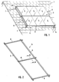
- Fig. 1 shows in the form of a schematic diagram arranged on a house roof 1 component group 2, comprising only exemplary six components 3, z.
- Example in the form of solar modules 4 comprising a plurality of solar cells serving for energy production.
- a frame structure 5 is provided, comprising two rails 6 running vertically here, which are fixed on the roof side via corresponding roof supports 7.
- Fastening means are arranged two support rails 8 on the rails 6 of the frame structure.
- the two support rails 8 are spaced and parallel to each other and traverse the rails 6 horizontally. They are part of a fastening device for the solar modules 4, which will be discussed in more detail below, which in turn are attached to the support rails 8 via suitable profile elements and retaining elements.
- suitable profile elements and retaining elements are suitable profile elements and retaining elements.
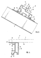
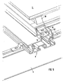
- Fig. 2 shows in an improved view of the frame structure 5 with the rails 6 and arranged thereon, usually screwed support profile rails 8, of which three are shown in the example shown.
- support profile rails 8 are used to attach a component 3, so each of a solar module, so that, based on such a solar module, each one support rail, the first support rail and the other support rail represents the second support rail.
- the supporting rails are all made the same
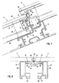
- Fig. 3 shows a sectional view through such a support profile 8.
- two vertically juxtaposed components 3 or 4 solar modules as this, starting from the example according to Fig.
- each support rail 8 in the central support rail 8 is the case, two mounting areas are formed on each support rail 8, a first mounting portion 9 consisting of a here T-shaped, ie both sides undercut groove 10 together with a support surface 11 and a limiting this stop 12, and a second Fastening region 13 in the form of an open towards the side, substantially C-shaped in cross-section receiving groove 14 having a lower support leg 15 and an upper leg 16 and a groove bottom 17.
- the two attachment areas 9 and 13 are obviously offset in height, the attachment area 9 is higher than the attachment area 13 Fig. 3
- the attachment of a support rail 8 is shown on a rail 6 of the base frame.
- two lateral T-slots 18 are provided, engage in the corresponding clamping plates 19, which in turn are fastened to the respective rail 6 via fastening screws, not shown.
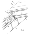
- Fig. 4 shows a partial view of a component 3, here a solar module 4 in the region of one of its edges, which may be either a side edge or the upper or lower edge of the component.
- a profile element 21 is arranged, usually glued, for which purpose the profile element 21 has a flat upper holding leg 22.
- a stiffening element eg of metal
- a stiffening element extending over the length of the profile element, which is preferably a rail, can be arranged.
- a first profile element 21 in the form of an over the entire vertical length of the solar cell module 4 extending rail 28 are arranged in the example shown.
- a not shown in detail, also designed as a profile rail profile element is disposed on the horizontal side 29.
- Both rails 28 are connected via a profile connector 30, which continues the respective profile rail form, and which also forms a profile element 21.
- the profile connector 30 as well as the horizontally extending, not shown profiled rail each have a profile section 23 which abuts against the stop web 12 of the first mounting portion 9. This limits the movement of the solar module, which is inclined at the mounting position downwards.
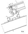
- a holding element 31 For fixing a holding element 31 is used, see Fig. 6 , a lower T-shaped hook portion 32, to which a longitudinal leg 33 connects, on which in turn a transverse leg 34 is arranged, the two lateral Holding portions 35 forms. Furthermore, two lateral stops 36 are provided.
- the holding element 31 which is flat in the region of its longitudinal limb, that is to say formed like a sheet with a thickness of 2-5 mm, will now be described in relation to FIGS Fig. 5 and 6 rotated by 90 ° position with the hook portion 32 inserted from above into the groove 10 and then by 90 ° in the in the Fig. 5 . 6 rotated position shown. Then, the hook portion 31 is pushed against the solar module 4 until the two stops 36 abut against the lower leg 25 of the profile section 23 of the profile connector 30, wherein in this position then a holding portion 35 has the holding web 24 overlapped surface, so that in connection with the hook portion 32 a clamping overlap is realized, which prevents lifting of the solar module.
- the design of the holding element 31, in particular the length of the stops 36, is dimensioned such that the two longitudinal narrow edge projections 37 of the adjacent profile elements 21 which protrude laterally by approximately 1 to 2 mm and prevent the glass edges of the module glass plates from contacting one another can abut, are only minimally spaced from each other, or directly adjacent to each other.
- Fig. 5 and 6 show the fixation of the lower edge of the component
- Fig. 7 the fixation of the upper edge of the component.
- Below the solar module 4 is also in the region of the upper edge a not shown here, parallel to the edge edge member 38 extending profile element 21 arranged in the form of a rail 28, which in turn via a profile connector 30, which in turn is a profile element 21, is connected to the vertically extending rail 28.
- the lower edge of the profile connector 30 and the horizontally extending rail 28 is now placed with the respective profile sections 23 on the support leg 15 of the second mounting portion 13 and then pushed a piece up until the profile section 23 in the C shaped receiving groove 14 is received and is overlapped by the legs 16.
- the lower component edge is placed on the first mounting portion 9 of the underlying support rail 8 and guided against the stop 12, as with respect to the Fig. 5 and 6 described. In any case, however, remains the profile section 23 of the profile connector 30 and the horizontally extending rail 28 in the C-shaped receiving groove 14, so that here is a backup against unintentional lifting is given. A further fixation in the region of the upper edge of the component does not take place, only against a horizontal displacement, as will be discussed below.
- a sealing element 39 is arranged, which extends over the entire horizontal width. It is arranged on the horizontally extending profile elements, ie the profile connector 30 and the horizontally extending, not shown rail 28. The fixation takes place in the groove 27, which serves as a clamping groove.
- the sealing element 39 has a corresponding slot 40, via which a clamping portion 54 is formed, which is inserted into the clamping groove 27. Furthermore, a downwardly projecting sealing lip 41 and a sealing loop 42 is provided on the inside.
- the solar module 4 is pushed under the sealing element 39, wherein the sealing lip 41 is deformed and sealingly rests on the upper side 43 of the lower solar module 4. This is a line seal in horizontal Direction reached.
- the upper solar module 4 thus overlaps the lower solar module 4, so that a shingled, shingled arrangement results.
- the sealing loop 42 can be compressed via the solar module 4, so that there is also a line seal.
- Fig. 7 Furthermore, shows a profiled member 44, which, as will be discussed below, extending in the vertical direction below the transition slot between two adjacent solar modules 4, against the sealing loop 42.
- This profile member 44 can via a projection 45 (eg., An inserted Pin), which engages behind the stop web 12, be fixed.
- the profile component 44 serving for sealing between two profile elements 21, here for example two profile rails 28, of two adjacent solar modules 4 shows Fig. 8 .
- the profile component 44 for example plastic, has a cross-sectional groove shape. It serves to seal the possibly remaining gap between the components 48. About two side portions 46, it engages in the grooves 27 of the rail 28 a. Evidently, the recess 47 resulting from the channel shape is below the possibly very narrow gap 48 between the immediately adjacent side edges of the two solar modules 4 and the edge projections 37. Any moisture entering via this gap 48 collects in the recess 47 and runs, After the arrangement is inclined, down to where it can be removed.
- the recess 47 may open slightly above the solar module below (in this area, if necessary, the sealing element 39 would be interrupted).
- a sealing web 49 on the profile component 44, for example, of a soft plastic material which, in the assembly position in the gap 48, seals it.
- the fixing methods described allow two components or a component group arranged one above the other to be moved horizontally.
- the outermost right and leftmost component of a row in the region of its lower component edge and its upper component edge is firmly connected to the support rail 8, see Fig. 9 .
- a claw-like holding member 52 is provided, which engages over the vertical web 53 of the profile connector 30, which is provided at its lower end and the part of the local profile section 23, and a suitable fastening screw together with the sliding block, the holding member 52 is then anchored in the groove 10 which can also be used to build up an anti-theft device.
- profile connectors 30, which themselves form profile elements 21, in the corner region of a component it is also possible to cut the profile rails miter and to connect via an inside simple corner connector by pressing. A bottom frame frame is then formed from only four rails with the inner corner connectors.
Abstract
Description
Die Erfindung betrifft eine Befestigungseinrichtung für an einem Gestellaufbau anzuordnende flächige Bauteile, insbesondere Solarmodule, umfassend eine erste und eine zweite, voneinander beabstandet, horizontal und parallel am Gestellaufbau anzuordnende Tragprofilschienen, an denen ein Bauteil im Bereich seiner einander gegenüberliegenden Ränder festlegbar ist.The invention relates to a fastening device for to be arranged on a frame structure planar components, in particular solar modules, comprising a first and a second, spaced from each other, horizontally and parallel to be arranged on the frame structure support rails on which a component in the region of its opposite edges can be fixed.
Großflächige Bauteile wie beispielsweise Solarmodule oder Sonnenkollektoren etc. werden üblicherweise im Freien, sei es freistehend oder auf Hausdächern, auf einem Gestellaufbau angeordnet. Der Gestellaufbau ist üblicherweise im Boden oder am Dach selbst verankert und besteht beispielsweise aus entsprechenden Seitenführungen, gebildet aus geeigneten Profilschienen, an denen über eine geeignete Befestigungseinrichtung die Bauteile fixiert werden. Eine solche Befestigungseinrichtung umfasst üblicherweise zwei parallel und beabstandet zueinander am Gestellaufbau anzuordnende Profilschienen, die sich zwischen den Gestellaufbauabschnitten erstrecken. An diesen Profilschienen werden die Bauteile randseitig oder mit Befestigungsmittel fixiert. Hierzu kommen üblicherweise Schraubbefestigungen zum Einsatz, also geeignete Halterungen, die an der jeweiligen Profilschiene festgeschraubt und in geeigneter Weise, häufig auch über Schraubverbindungen, fixiert werden. D. h., jedes einzelne Bauteil wird einzeln befestigt bzw. verschraubt, was während der Montage sehr aufwendig ist, als auch im Rahmen der Demontage, beispielsweise wenn ein Bauteil wegen Defekts auszutauschen ist.Large-area components such as solar modules or solar panels, etc. are usually arranged outdoors, whether freestanding or on house roofs, on a frame structure. The frame structure is usually anchored in the ground or on the roof itself and consists, for example, of corresponding side guides, formed of suitable profile rails, on which the components are fixed by means of a suitable fastening device. Such a fastening device usually comprises two parallel and spaced apart to be arranged on the frame structure rails extending between the frame mounting portions. On these rails, the components are fixed on the edge or with fastening means. For this purpose, usually threaded fasteners are used, so suitable brackets that are screwed to the respective rail and in a suitable manner, often via screw, fixed. D. h., Each individual component is individually fastened or screwed, which is very expensive during assembly, as well as in the context of disassembly, for example, if a component is to replace because of a defect.
Eine demgegenüber wesentlich einfachere Befestigungsmöglichkeit ist in der nachveröffentlichten deutschen Patentanmeldung
Die Erfindung liegt damit das Problem zu Grunde, eine Befestigungseinrichtung anzugeben, die ein sehr eng benachbartes Anordnen flächiger Bauteile, insbesondere von Solarmodulen, ermöglicht.The invention is thus based on the problem to provide a fastening device that allows a very closely adjacent arranging planar components, in particular of solar modules.
Zur Lösung dieses Problems ist bei einer Befestigungseinrichtung der eingangs genannten Art erfindungsgemäß vorgesehen, dass an der Unterseite eines rahmenlosen Bauteils im Bereich zumindest eines Teils der Seitenränder angeordnete Profilelemente mit einem zum Seitenrand vorspringenden Haltesteg vorgesehen sind, die der Verbindung mit den Tragprofilschienen dienen, und dass zum Verbinden eines Profilelements mit der ersten Tragprofilschiene ein Halteelement mit einem ersten Befestigungsabschnitt zum Befestigen an einem Befestigungsbereich der Tragprofilschiene und einem zweiten Befestigungsabschnitt mit zwei zu beiden Seiten vorspringenden Halteabschnitten, die in der Montagestellung die einander gegenüberliegenden Haltestege zweier nebeneinander festzulegender Bauteile übergreifen, vorgesehen ist.To solve this problem is inventively provided in a fastening device of the type mentioned that are provided on the underside of a frameless component in the region of at least a portion of the side edges arranged profile elements with a side edge projecting retaining web, which serve the connection with the support rails, and that for connecting a profile element to the first support rail, a holding element with a first attachment portion for attachment to a mounting region of the support rail and a second mounting portion with two projecting to both sides holding portions which engage over the opposite holding webs of two juxtaposed components in the mounting position, is provided.
Bei der erfindungsgemäßen Befestigungseinrichtung kommen zum einen nur rahmenlose Bauteile, also beispielsweise Solarmodule zum Einsatz, anders als im Stand der Technik, wo ausschließlich Bauteile mit umfassenden Rahmen vorgesehen sind. Bei der erfindungsgemäßen Befestigungseinrichtung sind demgegenüber an den Bauteilen nur an deren Unterseite angeordnete Profilelemente vorgesehen, die minimal, vorzugsweise ca. 1 - 2 mm, über die Seitenränder der Bauteile herausragen und so vermeiden, dass z. B. im Fall von Solarmodulen deren Glasscheiben aneinander liegen können. Die Profilelemente weisen einen vorzugsweise zum Seitenrand hin gerichteten Haltesteg auf, der mit einem Halteelement zusammenwirkt, das wiederum an einer Tragprofilschiene lösbar befestigt wird. Der Haltesteg könnte aber z. B. auch am Rand des Profilelements vertikal stehen, so dass seine obere freie Kante mit dem Halteelement zusammenwirkt. Das Halteelement selbst weist einen ersten Befestigungsabschnitt zum Befestigen an der Tragprofilschiene sowie einen zweiten Befestigungsabschnitt auf, mit dem es mit dem jeweiligen Haltesteg zweier benachbarter Bauteile zusammenwirken. D. h., die Fixierung der Bauteile an den Tragprofilschienen und damit am Gestellaufbau erfolgt ausschließlich im Bereich unterhalb der Bauteile, nachdem der klemmende Übergriff der Halteabschnitte über die Haltestege der Profilelemente im Bereich unterhalb der Bauteile erfolgt. Diese können deshalb in maximale Annäherung aneinander positioniert werden, d. h., sie können unmittelbar aneinander anliegen, mithin einander also auch berühren. Dies ermöglicht es folglich, die vorhandene Grundfläche maximal ausnutzen zu können, nachdem es bei Einsatz der erfindungsgemäßen Befestigungsvorrichtung keine zwingende Beabstandung der Bauteile auf Grund vorhandener umfassender Rahmen oder zwischen die Bauteile zu setzender Halteelemente gibt. Die Anordnung des oder der Profilelemente an der Bauteilunterseite reduziert ferner die aktive Fläche des als Solarmodul ausgeführten Bauteils nicht, anders als bei umfassenden Bauteilrahmen, bei denen die Rahmen die Bauteiloberseite randseitig übergreifen und so die aktive Fläche verkleinern.In the fastening device according to the invention, on the one hand, only frameless components, that is to say for example solar modules, are used, unlike in the prior art, where exclusively components with a comprehensive frame are provided are. In contrast, in the fastening device according to the invention arranged on the components only on the underside of profile elements are provided which protrude minimally, preferably about 1 - 2 mm, on the side edges of the components and so avoid z. B. in the case of solar modules whose glass sheets can lie against each other. The profile elements have a holding web, which is preferably directed towards the side edge, which interacts with a holding element, which in turn is releasably secured to a carrier profile rail. The jetty could but z. B. are also vertically on the edge of the profile element, so that its upper free edge cooperates with the holding element. The holding element itself has a first attachment portion for attachment to the support rail and a second attachment portion, with which it interacts with the respective holding web of two adjacent components. D. h., The fixation of the components to the support rails and thus the frame structure is carried out exclusively in the area below the components after the clamping engagement of the holding sections on the holding webs of the profile elements in the area below the components. These can therefore be positioned in maximum approach to each other, ie, they can lie directly against each other, and consequently also touch each other. This consequently makes it possible to make maximum use of the existing base area, since there is no compelling spacing of the components when using the fastening device according to the invention because of existing comprehensive frames or between the components to be set holding elements. Furthermore, the arrangement of the profile element or elements on the underside of the component does not reduce the active area of the component embodied as a solar module, unlike in the case of comprehensive component frames, in which the frames overlap the upper side of the component and thus reduce the active area.
Grundsätzlich besteht die Möglichkeit, ein Bauteil an der ersten und der zweiten Tragprofilschiene über derartige Halteelemente zu befestigen. Erfindungsgemäß besonders zweckmäßig ist es jedoch, die Bauteile nur an der ersten Tragprofilschiene über derartige Halteelemente zu befestigen und zum Fixieren an der zweiten Tragprofilschiene eine andere Haltemöglichkeit vorzusehen, die ebenfalls das Vorhandensein des unterhalb eines Bauteils befindlichen Haltestegs und Profilelements für eine Klemmsteckhalterung in Verbindung mit einer entsprechenden Klemmaufnahme an der zweiten Tragprofilschiene nutzt, worauf nachfolgend noch eingegangen wird.In principle, it is possible to attach a component to the first and the second support rail via such holding elements. However, according to the invention, it is particularly expedient to fasten the components only on the first support rail via such support elements and to provide a different holding possibility for fixing to the second support rail, which also the presence of the below one component support web and profile element for a clamping plug-in holder in conjunction with a corresponding clamping receptacle on the second support rail uses, which will be discussed below.
Die bauteilunterseitig angeordneten Profilelemente sind zweckmäßigerweise sich vertikal und horizontal erstreckende Profilschienen, die entweder auf Gehrung geschnitten im Bereich ihrer Ecken mittels vorzugsweise innenliegenden Eckverbindern miteinander verbunden sind, oder die über entsprechende sie eckseitig verbindende Profilverbinder, die dann die Profilelemente bilden, nachdem die Tragprofilschienenfixierung im Bereich der Ecken erfolgt, miteinander verbunden sind. Die Profilschienen haben in jedem Fall eine stabilisierende Funktion, nachdem erfindungsgemäß die Bauteile rahmenlos sind. Hierüber wird eine zu starke Durchbiegung der Bauteile in der Montagestellung verhindert, sei es in vertikaler oder in horizontaler Richtung.The component underside arranged profile elements are advantageously vertically and horizontally extending rails that are either mitred cut in the region of their corners by means of preferably inner corner connectors connected to each other or via corresponding corner connecting profile connector, which then form the profile elements after the support rail fixation in the area the corners take place, are interconnected. The rails have a stabilizing function in any case, according to the invention, the components are frameless. This prevents excessive bending of the components in the assembly position, be it in the vertical or in the horizontal direction.
Das Haltelement selbst ist im Wesentlichen T-förmig und weist einen Längsschenkel und einen an diesem angeordneten, die beiden Halteabschnitte bildenden Querschenkel auf, d. h., der Querschenkel greift beidseitig über die entsprechenden Haltestege der benachbarten Profilelemente. Das Halteelement kann ein- oder mehrteilig sein . Die jeweilige Tragprofilschiene, an der das Haltelement, das im Bereich des Längs- und Querschenkels einige mm, vorzugsweise 1-5 mm, insbesondere 2 mm, stark ist, befestigt wird, weist als Befestigungsbereich bevorzugt eine hinterschnittene Nut auf, während der erste Befestigungsabschnitt am Haltelement als Hakenabschnitt ausgebildet ist, über den das Halteelement in der hinterschnittenen Nuten in der Montagestellung einhakbar ist. Bevorzugt ist die Nut als doppelt hinterschnittene T-Nut und der Hakenabschnitt der Nutform entsprechend T-förmig ausgebildet. Dies lässt ein einfaches Einsetzen zu, der Hakenabschnitt ist lediglich von oben in die Nut einzusetzen und anschließend zu verdrehen, um ihn sicher zu fixieren. Das Haltelement ist in der Nut längsverschiebbar, kann also ohne weiteres an einer beliebigen Stelle eingesetzt und entsprechend in Position und damit Übergriff über den Haltesteg eines Profilelements geschoben werden.The holding element itself is essentially T-shaped and has a longitudinal limb and a transverse limb arranged on it, forming the two holding sections, ie the transverse limb engages on both sides via the corresponding holding webs of the adjacent profile elements. The holding element may be one or more parts. The respective support rail on which the holding element, which is strong in the region of the longitudinal and transverse leg a few mm, preferably 1-5 mm, in particular 2 mm, is fixed, preferably has an undercut groove as the attachment area, while the first attachment portion on Holding element is designed as a hook portion, via which the holding element in the undercut grooves in the mounting position can be hooked. Preferably, the groove is formed as a double undercut T-groove and the hook portion of the groove shape according to T-shaped. This allows for easy insertion, the hook portion is only inserted from above into the groove and then twisting to secure it securely. The holding element is longitudinally displaceable in the groove, so it can be readily used at any point and pushed accordingly in position and thus encroachment on the retaining web of a profile element.
Im Rahmen der Montage wird ein erstes Bauteil fixiert, wonach der oder die Haltelemente an ihm unter Übergriff über den Haltesteg positioniert werden und danach das zweite Bauteil herangeschoben wird. Um zu vermeiden, dass hierbei zwei benachbarte Bauteile mit ihren Seitenrändern, im Wesentlichen gebildet durch die freiliegende Glasplattenkante im Falle eines Solarmoduls, beim Aneinanderschieben direkt aneinander schlagen - sofern dies nicht bereits durch die gegebenenfalls seitlich um ca. 1 - 2 mm vorspringenden Profilelementen sichergestellt ist -, ist zweckmäßigerweise an einem Haltelement wenigstens ein in der Montagestellung die benachbarten Profilelemente gegenlagernder Anschlag vorgesehen, an dem beide Bauteile über ihre jeweiligen Profilelemente anliegen und über den sie und damit die Bauteile definiert beabstandet werden. Der Anschlag ist dabei so ausgelegt und positioniert, dass die Profilelemente dagegen laufen und gleichzeitig die Seitenränder der Bauteile in eine gewünschte möglichst nahe Anlage aneinander positioniert werden.As part of the assembly, a first component is fixed, after which the one or more holding elements are positioned on him under attack over the retaining web and then the second component is pushed. In order to avoid that in this case two adjacent components with their side edges, formed essentially by the exposed glass plate edge in the case of a solar module, when pushed together directly beat each other - if this is not already ensured by the optionally laterally by about 1 - 2 mm projecting profile elements - Is expediently provided on a holding element at least one in the mounting position, the adjacent profile elements gegenlagernder stop on which abut both components via their respective profile elements and on which they and thus the components are spaced defined. The stopper is designed and positioned so that the profile elements run against it and at the same time the side edges of the components are positioned in a desired as close as possible contact each other.
Nachdem Solarmodule üblicherweise schrägstehend angeordnet werden, sieht eine zweckmäßige Weiterbildung vor, am ersten Befestigungsbereich einer Tragprofilschiene einen vorzugsweise stegförmigen Anschlag für das oder die im Bereich des unteren Bauteilrands angeordneten Profilelemente vorzusehen. Beim Anordnen eines Bauteils wird dieses beispielsweise zunächst im Bereich seines oberen Randes auf die nachfolgend noch beschriebene bevorzugte Weise fixiert, wonach das Bauteil mit seinem unteren Rand abgesenkt wird, bis das oder die Profilelemente auf der Tragprofilschiene aufliegen und wegbegrenzt an dem stegförmigen Anschlag anliegen, über den ein weiteres Abrutschen verhindert wird, wonach auf einfache Weise die Fixierung über die Halteelemente erfolgt.After solar modules are usually arranged at an angle, an expedient development provides for a preferably web-shaped stop for the profile element (s) arranged in the region of the lower component edge on the first fastening region of a carrier profile rail. When arranging a component of this example, first fixed in the region of its upper edge in the preferred manner described below, after which the component is lowered with its lower edge until the or the profile elements rest on the support rail and wegbegrenzt abut the web-shaped stop over the further slipping is prevented, after which takes place in a simple way the fixation on the holding elements.
Wie beschrieben besteht grundsätzlich die Möglichkeit, die Bauteile im Bereich sowohl des unteren als auch des oberen Randes unter Verwendung eines beschriebenen Halteelements zu fixieren. Eine zweckmäßige Erfindungsausgestaltung sieht jedoch vor, dies nur im Bereich des unteren Randes zur Fixierung an einer ersten Tragprofilschiene vorzunehmen und im Bereich des oberen Bauteilrandes zur Befestigung an der zweiten Tragprofilschiene eine andere Befestigungsmöglichkeit vorzusehen. Hierzu weist die gegebenenfalls zweite Tragprofilschiene einen zweiten Befestigungsbereich in Form einer zum Bauteilrand offenen, im Wesentlichen C-förmigen Aufnahmenut auf, in die der Haltesteg des oder der dortigen Profilelemente, von einem Schenkel der Aufnahmenut übergriffen, eingreift. Es erfolgt hier eine einfache Steckklemmhalterung, indem der Rand des Profilelements mit dem vorspringenden Haltesteg in die offene Aufnahmenut eingesteckt wird, so dass der Haltesteg von der Aufnahmenutschulter übergriffen und gegen ein Anheben fixiert wird. D. h., im Rahmen der Montage ist lediglich der Profilelementabschnitt mit dem Haltesteg in die Aufnahmenut von unten her einzuschieben, wonach das Bauteil abgesenkt wird, bis das oder die unteren Profilelemente auf der unteren Tragprofilschiene aufsitzen und gegen den dortigen Anschlagsteg laufen, wonach sofort die Fixierung über das Halteelement erfolgen kann.As described, it is basically possible to fix the components in the region of both the lower and the upper edge using a described holding element. However, an expedient embodiment of the invention provides that this is done only in the region of the lower edge for fixing to a first support rail and to provide another mounting option in the region of the upper edge of the component for attachment to the second support rail. For this purpose, the optionally second support rail a second fastening area in the form of a component edge open, substantially C-shaped receiving groove into which the holding web of the local profile elements or, engages over a leg of the receiving groove, engages. It takes place here a simple Steckklemmhalterung by the edge of the profile element is inserted with the projecting retaining web in the open receiving groove, so that the holding web is overlapped by the Aufnahmutschulter and fixed against lifting. D. h., As part of the assembly, only the profile element section is to be inserted with the holding web in the receiving groove from below, after which the component is lowered until the or the lower profile elements sit on the lower support rail and run against the local stop web, which immediately the fixation can be done via the retaining element.
Eine besonders zweckmäßige Weiterbildung sieht vor, dass an jeder Tragschiene der erste und der zweite Befestigungsbereich ausgebildet ist, d. h., die Schienen sind insoweit identisch ausgebildet so dass insgesamt nur ein Profil vorrätig gehalten werden muss, das die beiden erfindungsgemäßen Befestigungsmöglichkeiten bietet.A particularly expedient refinement provides that the first and the second attachment region are formed on each support rail, that is to say the first and second attachment regions. h., The rails are so far identical design so that a total of only one profile must be kept in stock, which offers the two mounting options according to the invention.
Dabei ist nach einer zweckmäßigen Weiterbildung der Erfindung in der Montagestellung der erste Befestigungsbereich höher als der zweite Befestigungsbereich angeordnet. Wie beschrieben erfolgt die Fixierung über die Profilelemente stets im Bereich des zur Seite oder vertikal vorspringenden Haltestegs. Dieser ist bezogen auf die Unterseite eines Bauteils, da umlaufend, stets in gleicher Position. Liegt nun der erste Befestigungsbereich höher als der zweite Befestigungsbereich, so führt dies zwangsläufig dazu, dass in der Montagestellung das Bauteil relativ gesehen im unteren Randbereich, wo es am ersten Befestigungsbereich angeordnet wird, etwas höher liegt als im oberen Randbereich, wo es am zweiten Befestigungsbereich fixiert ist. Dies bietet nun die besonders vorteilhafte Möglichkeit, zwei übereinander angeordnete Bauteile etwas miteinander zu überlappen. Denn in Folge des höhenmäßigen Versatz der beiden Befestigungsabschnitte kann der obere Randbereich eines unteren Bauteils unter den unteren Randbereich eines oberen Bauteils geschoben und angeordnet werden. D. h., der untere Randbereich des oberen Bauteils überlappt etwas über den oberen Randbereich des unteren Bauteils, so dass sich eine quasi geschuppte Anordnung, gesehen in vertikaler Richtung, bei gleichzeitiger Möglichkeit einer nahezu unmittelbar aneinanderliegenden Anordnung in horizontaler Richtung realisieren lässt. Dies bietet nun die Möglichkeit, solche Bauteile quasi als Dachziegelersatz zu verwenden, mithin also das Dach über diese Bauteile selbst zu decken (in-Dach-Ausführung).In this case, according to an expedient development of the invention, the first fastening region is arranged higher than the second fastening region in the assembly position. As described, the fixation via the profile elements always takes place in the region of the side or vertically projecting holding web. This is relative to the underside of a component, as revolving, always in the same position. If the first fastening region now lies higher than the second fastening region, then this inevitably leads to the component being arranged somewhat higher in the lower edge region where it is arranged on the first fastening region than in the upper edge region, where it is on the second fastening region is fixed. This now offers the particularly advantageous possibility of overlapping two superimposed components slightly with each other. Because as a result of the height-wise offset of the two fastening portions, the upper edge region of a lower component can be pushed and arranged below the lower edge region of an upper component. That is, the lower edge area of the upper component overlaps slightly above the upper edge region of the lower component, so that a quasi-shingled arrangement, seen in the vertical direction, can be realized with the simultaneous possibility of a nearly immediately adjacent arrangement in the horizontal direction. This now offers the possibility to use such components virtually as a roof tile substitute, so therefore to cover the roof itself about these components (in-roof version).
Insbesondere bei einer solchen Anordnung, aber auch dann, wenn die Bauteile nicht versetzt und überlappt, sondern ebenenparallel angeordnet werden, ist es zweckmäßig, an dem in der Montagestellung unteren horizontal verlaufenden und als Profilschiene ausgebildeten Profilelement ein sich im gegebenenfalls vorgesehenen Profilverbinder gegebenenfalls fortsetzendes Dichtelement vorzusehen, an dem in der Montagestellung der Rand des unterhalb davon angeordneten Bauteils anliegt. Hierüber wird vorteilhaft eine Dichtung im Bereich des horizontalen Spalts zwischen zwei Bauteilen ermöglicht.In particular, in such an arrangement, but also when the components are not offset and overlapping, but are arranged parallel to the plane, it is expedient to provide at the lower in the mounting position horizontally extending and designed as a profile rail profile element in the optionally provided profile connector optionally continuing sealing element in which, in the assembly position, the edge of the component arranged below it rests. This advantageously allows a seal in the region of the horizontal gap between two components.
Um auch in Längsrichtung grundsätzlich eine Dichtmöglichkeit vorzusehen, um zu vermeiden, dass durch den sich auch bei einander (fast) berührenden Bauteilen im Bereich der Längsseitenränder ergebenden Kapillarspalt Feuchtigkeit nach unten absondert, ist zweckmäßigerweise zwischen zwei einander gegenüberliegenden Profilelementen ein sich bezogen auf die Montagestellung in Längsrichtung erstreckendes und unterhalb des Übergangsspaltes zwischen zwei benachbarten Bauteilen verlaufendes, gegebenenfalls auch der Aussteifung dienendes Profilbauteil vorgesehen. Dieses Profilbauteil kann beispielsweise aus Kunststoff oder Metall sein und erstreckt sich über die Länge eines länglichen, rechteckigen Bauteils (dessen Länge beträgt beispielsweise ca. 1,7 m, während die Breite ca. 1 m beträgt). Das Profilbauteil verläuft genau unterhalb des sich ergebenden schmalen Spaltes und nimmt darüber eindringendes Tropfwasser auf und leitet es nach unten ab, wo es in Folge entweder der Fortsetzung des Profilbauteils zum nächsten Bauteil oder der überlappten Anordnung abgeleitet werden kann.In order to provide a sealing possibility also in the longitudinal direction, in order to avoid that due to the capillary gap resulting in each other (almost) touching components in the region of the longitudinal side edges moisture drops down, is expediently between two opposing profile elements with respect to the mounting position in Provided longitudinally extending and extending below the transition gap between two adjacent components, optionally also the stiffener serving profile component. This profile component may for example be made of plastic or metal and extends over the length of an elongated, rectangular component (the length of which is, for example, about 1.7 m, while the width is about 1 m). The profile member extends just below the resulting narrow gap and receives dripping water passing over it and discharges it down where it can be derived as a result of either the continuation of the profile member to the next member or the overlapped assembly.
In jedem Fall ist zweckmäßigerweise an jedem Profilelement ein seitlich offener Aufnahme- oder Klemmabschnitt für einen Klemmabschnitt des Dichtelements oder des Seitenschenkels des Profilbauteils vorgesehen. Hierüber kann eine einfache Fixierung des Dichtelements, beispielsweise eines Gummidichtelements, das hinreichend verformbar ist und beispielsweise eine Dichtlippe oder dergleichen aufweist, oder des Profilbauteils, das als Metallteil oder auch als hinreichend steifes Kunststoffteil ausgeführt sein kann, erreicht werden.In any case, it is expedient for each profile element to have a laterally open receiving or clamping section for a clamping section of the sealing element or the side leg of the profile component provided. This can be a simple fixation of the sealing element, for example a rubber sealing element, which is sufficiently deformable and, for example, a sealing lip or the like, or the profile component, which can be designed as a metal part or as a sufficiently rigid plastic part, can be achieved.
Um eine sichere Auflage der Profilelemente auf den Tragprofilschienen zu sorgen, ist zweckmäßigerweise an zumindest einem Teil der Auflageflächen der Profilelemente eine zahn- oder rillenartige Oberflächenstruktur vorgesehen.In order to ensure a secure support of the profile elements on the support profile rails, a tooth or groove-like surface structure is expediently provided on at least part of the bearing surfaces of the profile elements.
Ferner kann ein Profilelement, insbesondere soweit dieses als Profilschiene ausgebildet ist, wenigstens eine Hohlkammer aufweisen, in der ein Aussteifungselement angeordnet ist. Dieser z. B. aus Metall, vorzugsweise Aluminium (wie die Profilelemente selbst) bestehende Aussteifungselement dient der Versteifung des gesamten Bauteils, um Längs- bzw. Querbiegungen zu vermeiden.Furthermore, a profile element, in particular as far as this is designed as a profile rail, have at least one hollow chamber in which a stiffening element is arranged. This z. B. of metal, preferably aluminum (such as the profile elements itself) existing stiffening element serves to stiffen the entire component in order to avoid longitudinal or transverse bending.
Neben der Befestigungseinrichtung selbst betrifft die Erfindung ferner eine Bauteilgruppe, insbesondere Solarmodulgruppe, die auf einem Gestellaufbau angeordnet ist, bei welcher mehrere nebeneinander angeordnete, rahmenlose Bauteile unter Verwendung einer Befestigungseinrichtung der beschriebenen Art zu einem Verbund zusammengesetzt sind. Dabei ist es bei der erfindungsgemäßen Bauteilgruppe lediglich erforderlich, an den äußeren Bauteilen eine Diebstahlsicherung vorzusehen, da die inneren Bauteile über die Halteelemente und die bevorzugte Klemmsteck-Fixierung am anderen Bauteilrand sicher und ohne Lösen der Diebstahlsicherungsvorrichtung nicht entnehmbar angeordnet sind.In addition to the fastening device itself, the invention further relates to a component group, in particular solar module group, which is arranged on a frame structure in which a plurality of juxtaposed, frameless components are assembled using a fastening device of the type described in a composite. It is only necessary in the component group according to the invention to provide an anti-theft device to the outer components, since the inner components on the holding elements and the preferred clamping plug fixation on the other edge of the component are not removable and not detachable without loosening the anti-theft device.
Weitere Vorteile, Merkmale und Einzelheiten der Erfindung ergeben sich aus dem im Folgenden beschriebenen Ausführungsbeispiels sowie anhand der Zeichnung. Dabei zeigen:
- Fig. 1
- eine Prinzipdarstellung einer erfindungsgemäßen Bauteilgruppe in Form von Solarmodulen, montiert auf einem Hausdach,
- Fig. 2
- eine Darstellung des Gestellaufbaus mit daran angeordneten Trag-profilschienen,
- Fig. 3
- eine Schnittansicht entlang der Linie III-III in
Fig. 2 durch eine Trag-profilschiene, - Fig. 4
- eine Schnittansicht durch ein Profilelement zur Darstellung von dessen Grundstruktur,
- Fig. 5
- eine Ansicht eines Bauteils in Form eines Solarmoduls mit darin angeordneten Profilelementen im Bereich seines unteren Randes in der Montagestellung an einer Tragprofilschiene mit einem Halteelement,
- Fig. 6
- eine Seitenansicht, teilweise im Schnitt, der Anordnung aus
Fig. 5 , - Fig. 7
- eine Seitenansicht des Bauteils aus den
Fig. 5 und6 im Bereich seines oberen Bauteilrandes in der Montagestellung an der zweiten Tragprofilschiene nebst Darstellung des ebenfalls an dieser Tragprofilschiene montierten anderen Bauteils, - Fig. 8
- eine Ansicht zweier montierter, nebeneinander angeordneter Bauteile im Bereich ihrer aneinanderliegender Längskanten mit eingesetztem Profilbauteil, und
- Fig. 9
- eine Ansicht des äußeren Bauteils im Bereich seiner Außenkante zur Darstellung der randseitigen Montage.
- Fig. 1
- a schematic diagram of a component group according to the invention in the form of solar modules, mounted on a house roof,
- Fig. 2
- an illustration of the frame structure with supporting profile rails arranged thereon,
- Fig. 3
- a sectional view taken along the line III-III in
Fig. 2 by a support profile rail, - Fig. 4
- a sectional view through a profile element to illustrate its basic structure,
- Fig. 5
- a view of a component in the form of a solar module with therein profiled elements in the region of its lower edge in the mounting position on a support rail with a holding element,
- Fig. 6
- a side view, partially in section, the arrangement of
Fig. 5 . - Fig. 7
- a side view of the component of the
Fig. 5 and6 in the region of its upper component edge in the assembly position on the second support rail together with the representation of the other component likewise mounted on this support rail, - Fig. 8
- a view of two assembled, juxtaposed components in the region of their juxtaposed longitudinal edges with inserted profile component, and
- Fig. 9
- a view of the outer member in the region of its outer edge to illustrate the edge mounting.
Die
Zur Fixierung wird ein Halteelement 31 verwendet, das, siehe
Das Halteelement 31, das im Bereich seines Längsschenkels flach, also blechartig mit einer Stärke von 2-5 mm ausgebildet ist, wird nun in einer bezogen auf die
Zur Montage eines nächsten Solarmoduls 4 wird dieses in entsprechender Weise mit seinem unteren Randbereich bzw. den dort vorgesehenen Profilelementen 21 (Profilschiene 28 und Profilverbinder 30) auf den ersten Befestigungsabschnitt 9 aufgelegt und gegen den Anschlagsteg 12 geführt und sodann gegen das bereits angeordnete Solarmodul 4 geschoben. Hierbei läuft der entsprechende Profilabschnitt 23 des an der benachbarten Solarmodulseite befindlichen Profilverbinders 30, der bei der gezeigten Ausführung im Bereich des Profilabschnitt 23 einen kurzen Vertikalsteg 53 aufweist, gegen die andere Seite der Anschläge 36 des bereits gesetzten Halteelements 31, der dortige Haltesteg 24 des Profilverbinders 30 wird unter den zweiten Halteabschnitt 35 des Halteelements 31 geschoben, so dass auch dieses Bauteil dann lagefest gesichert ist. Die Ausgestaltung des Halteelements 31, insbesondere die Länge der Anschläge 36, ist dabei so bemessen, dass die beiden längs laufenden schmalen Randvorsprünge 37 der benachbarten Profilelemente 21, die um ca. 1 - 2 mm seitlich vorspringen und verhindern, dass die Glaskanten der Modulglasplatten aneinander anliegen können, nur minimal voneinander beabstandet sind, bzw. direkt aneinander anliegend.For mounting a next
Während die
In
Wie
Wie
Eine solche Anordnung eines der Abdichtung dienenden Profilbauteils 44 zwischen zwei Profilelementen 21, hier beispielsweise zweier Profilschienen 28, zweier benachbarter Solarmodule 4 zeigt
Wie
Die beschriebenen Fixierungsweisen lassen es zu, zwei übereinander angeordnete Bauteile bzw. eine Bauteilgruppe noch horizontal zu verschieben. Um die gesamte Gruppe bzw. eine horizontale Bauteilreihe auch hiergegen zu fixieren, wird jeweils das äußerste rechte und äußerste linke Bauteil einer Reihe im Bereich seines unteren Bauteilrandes und seines oberen Bauteilrandes fest mit dem der Tragprofilschiene 8 verbunden, siehe
Anstelle einer Anordnung von Profilverbindern 30, die selber Profilelemente 21 bilden, im Eckbereich eines Bauteils ist es auch möglich, die Profilschienen auf Gehrung zu schneiden und über einen innen liegenden einfachen Eckverbinder durch Verpressen zu verbinden. Ein unterseitig umlaufender Rahmen wird dann aus nur vier Profilschienen mit den innen liegenden Eckverbindern gebildet.Instead of an arrangement of
Claims (17)
Applications Claiming Priority (1)
| Application Number | Priority Date | Filing Date | Title |
|---|---|---|---|
| DE102007027997A DE102007027997B4 (en) | 2007-06-14 | 2007-06-14 | Fastening device for to be arranged on a frame structure surface frameless components, in particular solar modules |
Publications (3)
| Publication Number | Publication Date |
|---|---|
| EP2003405A2 true EP2003405A2 (en) | 2008-12-17 |
| EP2003405A3 EP2003405A3 (en) | 2012-07-18 |
| EP2003405B1 EP2003405B1 (en) | 2014-01-01 |
Family
ID=39777080
Family Applications (1)
| Application Number | Title | Priority Date | Filing Date |
|---|---|---|---|
| EP08007003.0A Not-in-force EP2003405B1 (en) | 2007-06-14 | 2008-04-09 | Fixing device for flat components attachable to a framework, in particular for solar modules |
Country Status (3)
| Country | Link |
|---|---|
| US (1) | US8104239B2 (en) |
| EP (1) | EP2003405B1 (en) |
| DE (1) | DE102007027997B4 (en) |
Cited By (10)
| Publication number | Priority date | Publication date | Assignee | Title |
|---|---|---|---|---|
| WO2009137887A1 (en) * | 2008-05-16 | 2009-11-19 | Kerryj Investment Pty Ltd | Mounting system |
| AU2009101302B4 (en) * | 2008-05-16 | 2010-07-15 | Kerryj Investment Pty Ltd | Mounting system |
| WO2011045185A3 (en) * | 2009-10-12 | 2011-09-15 | Fischer Lichtsysteme Gmbh | Installation system for solar modules and solar energy plant comprising the installation system |
| FR2972471A1 (en) * | 2011-03-10 | 2012-09-14 | Centurywatt | COATING A ROOF PAN WITH STANDARD LAMINATED OR BI-GLASS PHOTOVOLTAIC PANELS |
| WO2012143006A1 (en) * | 2011-04-21 | 2012-10-26 | Fath Solar Group Holding Gmbh | Solar module |
| ITVI20110185A1 (en) * | 2011-07-13 | 2013-01-14 | Aulusplan S R L | ASSEMBLY OF SOLAR PANELS |
| EP2546585A1 (en) * | 2011-07-12 | 2013-01-16 | Mauro Pula | Integrated system of panels |
| EP2525167A3 (en) * | 2011-05-20 | 2014-07-30 | Robert Bosch Gmbh | Fastening device for at least one solar collector |
| EP2426432A3 (en) * | 2010-09-01 | 2015-03-18 | Mounting Systems GmbH | Profile rail, holding element and solar module assembly comprising same, in particular for a horizontal assembly of solar modules |
| FR3032263A1 (en) * | 2015-02-04 | 2016-08-05 | Ciel Et Terre Int | FIXING PANEL WITH ADJUSTABLE ENTRAX |
Families Citing this family (62)
| Publication number | Priority date | Publication date | Assignee | Title |
|---|---|---|---|---|
| US7434362B2 (en) * | 2001-07-20 | 2008-10-14 | Unirac, Inc. | System for removably and adjustably mounting a device on a surface |
| US9151056B2 (en) * | 2008-04-17 | 2015-10-06 | Konvin Associates, L.P. | Dual glazing panel system |
| FR2945609B1 (en) * | 2009-05-12 | 2013-03-29 | Avancis Gmbh & Co Kg | FIXING DEVICE AND METHOD FOR MOUNTING SOLAR MODULES. |
| US20120298817A1 (en) * | 2009-07-02 | 2012-11-29 | John Raymond West | Pivot-Fit Frame, System and Method for Photovoltaic Arrays |
| FR2951479B1 (en) * | 2009-10-16 | 2014-01-17 | Wilson Coelho | SUPPORT STRUCTURE OF SOLAR PANELS FOR BUILDING ROOF |
| US20110209422A1 (en) * | 2010-02-18 | 2011-09-01 | King Zachary A | Method and apparatus for mounting photovoltaic modules to shingled surfaces |
| US8595996B2 (en) * | 2010-02-26 | 2013-12-03 | General Electric Company | Photovoltaic framed module array mount utilizing asymmetric rail |
| US8495839B2 (en) * | 2010-04-01 | 2013-07-30 | Yanegijutsukenkyujo Co., Ltd. | Installation structure of solar cell module |
| US20110277296A1 (en) * | 2010-05-17 | 2011-11-17 | Ramos Andrew R | Composite system to support solar panels on polymer covers on landfills |
| US8984751B2 (en) * | 2010-05-17 | 2015-03-24 | Andrew R Ramos | Composite configurable system to support solar panels on geomembrane |
| FR2961300B1 (en) * | 2010-06-14 | 2014-05-09 | Inst Rech Fondamentale En Technologies Solaires Irfts | STRUCTURE FOR SOLIDARIZING PHOTOVOLTAIC PANELS ON A BUILDING |
| US9239173B2 (en) | 2010-09-30 | 2016-01-19 | Apollo Precision (Fujian) Limited | Photovoltaic module support with interface strips |
| US9074796B2 (en) | 2010-09-30 | 2015-07-07 | Apollo Precision (Kunming) Yuanhong Limited | Photovoltaic module support clamp assembly |
| US9182152B2 (en) | 2010-09-30 | 2015-11-10 | Apollo Precision (Fujian) Limited | Photovoltaic module support with cable clamps |
| US20120097816A1 (en) * | 2010-10-20 | 2012-04-26 | D Three Enterprises, Llc | Combination mounting and grounding clip |
| US8656658B2 (en) | 2010-10-20 | 2014-02-25 | Miasole | Retainers for attaching photovoltaic modules to mounting structures |
| FR2968376A1 (en) * | 2010-12-06 | 2012-06-08 | Auversun | Joint assembly for ensuring sealing between frames of photovoltaic panels on roof, has joint sealed to water and non-sealed to air, where joint and another joint are equipped with active parts adapted to be deformed by crushing |
| DE102011084556A1 (en) * | 2011-01-12 | 2012-07-12 | Mounting Systems Gmbh | Mounting system for mounting solar modules on a trapezoidal sheet |
| DE102011013147B4 (en) * | 2011-03-04 | 2020-07-02 | Hpf Gmbh | Solar roof |
| US8601755B2 (en) * | 2011-03-28 | 2013-12-10 | 1541689 Ontario Inc. | Solar panel supports |
| US8776454B2 (en) * | 2011-04-05 | 2014-07-15 | Michael Zuritis | Solar array support structure, mounting rail and method of installation thereof |
| JP5795909B2 (en) * | 2011-08-31 | 2015-10-14 | 元旦ビューティ工業株式会社 | Solar cell module connection structure and connection method |
| TWI425646B (en) * | 2012-01-06 | 2014-02-01 | Au Optronics Corp | Frame element of photovoltaic device, the photovoltaic device and photovoltaic array system having the photovoltaic device |
| US9316417B2 (en) * | 2012-06-29 | 2016-04-19 | Sunpower Corporation | Framing system for mounting solar collecting devices |
| JP2014103337A (en) * | 2012-11-22 | 2014-06-05 | Honda Motor Co Ltd | Solar cell module |
| US9273885B2 (en) * | 2013-06-13 | 2016-03-01 | Building Materials Investment Corporation | Roof integrated photovoltaic system |
| US10256765B2 (en) | 2013-06-13 | 2019-04-09 | Building Materials Investment Corporation | Roof integrated photovoltaic system |
| US8938932B1 (en) * | 2013-12-13 | 2015-01-27 | Quality Product Llc | Rail-less roof mounting system |
| EP3132101A1 (en) * | 2014-04-16 | 2017-02-22 | Control y Desarrollo Empresarial, S.L. | Covering comprising cover plates clamped to profiles |
| US9670672B2 (en) * | 2014-12-03 | 2017-06-06 | Aleksandar Stevanov | Roof panel system |
| US20170133529A1 (en) * | 2015-11-05 | 2017-05-11 | Solarworld Industries Sachsen Gmbh | Photovoltaic modules and method of manufacturing a photovoltaic module |
| US20190207555A1 (en) * | 2016-12-27 | 2019-07-04 | Hall Labs Llc | Solar shingle installation and interconnection system |
| US11012024B2 (en) * | 2018-07-03 | 2021-05-18 | Building Materials Investment Corporation | Roof integrated photovoltaic system with improved serviceability |
| US11894797B1 (en) * | 2019-06-06 | 2024-02-06 | Powershingle, Llc | Solar support structures and methods |
| MX2022006401A (en) | 2019-11-27 | 2022-10-27 | GAF Energy LLC | Roof integrated photovoltaic module with spacer. |
| US11398795B2 (en) | 2019-12-20 | 2022-07-26 | GAF Energy LLC | Roof integrated photovoltaic system |
| MX2022009069A (en) | 2020-01-22 | 2023-01-05 | GAF Energy LLC | Integrated photovoltaic roofing shingles, methods, systems, and kits thereof. |
| CA3168056A1 (en) | 2020-02-18 | 2021-08-26 | Richard Perkins | Photovoltaic module with textured superstrate providing shingle-mimicking appearance |
| WO2021174009A1 (en) | 2020-02-27 | 2021-09-02 | GAF Energy LLC | Photovoltaic module with light-scattering encapsulant providing shingle-mimicking appearance |
| CA3174687A1 (en) | 2020-03-30 | 2021-10-07 | Bmic Llc | Interlocking laminated structural roofing panels |
| CA3174671A1 (en) | 2020-04-09 | 2021-10-14 | GAF Energy LLC | Three-dimensional laminate photovoltaic module |
| US11217715B2 (en) | 2020-04-30 | 2022-01-04 | GAF Energy LLC | Photovoltaic module frontsheet and backsheet |
| US11177639B1 (en) | 2020-05-13 | 2021-11-16 | GAF Energy LLC | Electrical cable passthrough for photovoltaic systems |
| US11251744B1 (en) | 2020-06-04 | 2022-02-15 | GAF Energy LLC | Photovoltaic shingles and methods of installing same |
| US11843067B2 (en) | 2020-07-22 | 2023-12-12 | GAF Energy LLC | Photovoltaic modules |
| WO2022051593A1 (en) | 2020-09-03 | 2022-03-10 | GAF Energy LLC | Building integrated photovoltaic system |
| US11545928B2 (en) | 2020-10-13 | 2023-01-03 | GAF Energy LLC | Solar roofing system |
| US11444569B2 (en) | 2020-10-14 | 2022-09-13 | GAF Energy LLC | Mounting apparatus for photovoltaic modules |
| US11454027B2 (en) | 2020-10-29 | 2022-09-27 | GAF Energy LLC | System of roofing and photovoltaic shingles and methods of installing same |
| MX2021013676A (en) | 2020-11-09 | 2022-05-10 | Bmic Llc | Interlocking structural roofing panels with integrated solar panels. |
| WO2022103968A1 (en) | 2020-11-12 | 2022-05-19 | GAF Energy LLC | Roofing shingles with handles |
| WO2022103841A1 (en) | 2020-11-13 | 2022-05-19 | GAF Energy LLC | Photovoltaic module systems and methods |
| US11459757B2 (en) | 2021-01-19 | 2022-10-04 | GAF Energy LLC | Watershedding features for roofing shingles |
| EP4295414A1 (en) | 2021-02-19 | 2023-12-27 | Gaf Energy LLC | Photovoltaic module for a roof with continuous fiber tape |
| CN112865693A (en) * | 2021-03-30 | 2021-05-28 | 高邮市瑞久金属材料有限公司 | Long life's of bilayer structure aluminium system frame for solar panel |
| US11527665B2 (en) | 2021-05-06 | 2022-12-13 | GAF Energy LLC | Photovoltaic module with transparent perimeter edges |
| WO2022256430A1 (en) | 2021-06-02 | 2022-12-08 | GAF Energy LLC | Photovoltaic module with light-scattering encapsulant providing shingle-mimicking appearance |
| US11512480B1 (en) | 2021-07-16 | 2022-11-29 | GAF Energy LLC | Roof material storage bracket |
| WO2023034432A1 (en) | 2021-09-01 | 2023-03-09 | GAF Energy LLC | Photovoltaic modules for commercial roofing |
| WO2023141566A1 (en) | 2022-01-20 | 2023-07-27 | GAF Energy LLC | Roofing shingles for mimicking the appearance of photovoltaic modules |
| US11811361B1 (en) | 2022-12-14 | 2023-11-07 | GAF Energy LLC | Rapid shutdown device for photovoltaic modules |
| DE202024100335U1 (en) | 2024-01-23 | 2024-02-02 | Pentagon, Warenhandels- und Verlagsgesellschaft mbH | Mounting system for photovoltaic modules and other flat elements |
Citations (2)
| Publication number | Priority date | Publication date | Assignee | Title |
|---|---|---|---|---|
| DE102004044103A1 (en) | 2003-09-17 | 2005-04-21 | Michael Buechele | Device for attaching solar modules to attachment profiles has clamp part with arm that interacts with clamp bolt to clamp carrying profile mounting flange, insertion arm for inserting mounting flange of another carrying profile, support |
| DE102006053831A1 (en) | 2006-11-14 | 2008-05-15 | Fath Gmbh | Fastening device for e.g. solar module, has retaining plate including fastening section for fastening to profile rail, and another fastening section including insertion through hole for retaining pin of frame component |
Family Cites Families (25)
| Publication number | Priority date | Publication date | Assignee | Title |
|---|---|---|---|---|
| DE3611542A1 (en) * | 1986-04-05 | 1987-10-08 | Remscheid Volksbank | Solar module |
| DE59207833D1 (en) | 1991-09-11 | 1997-02-20 | Siemens Solar Gmbh | Mounting clamp |
| KR960702041A (en) * | 1993-04-22 | 1996-03-28 | 리차드 위딩톤 | Planed Roof Assembly (IMPROVED SHINGLE ROOFlNG ASSEMBLY) |
| US5460660A (en) | 1993-07-21 | 1995-10-24 | Photon Energy, Inc. | Apparatus for encapsulating a photovoltaic module |
| US6111189A (en) * | 1998-07-28 | 2000-08-29 | Bp Solarex | Photovoltaic module framing system with integral electrical raceways |
| DE19934073B4 (en) * | 1999-07-19 | 2005-08-25 | Regen Energiesysteme Gmbh | Device for fixing solar modules |
| US7012188B2 (en) * | 2000-04-04 | 2006-03-14 | Peter Stuart Erling | Framing system for solar panels |
| EP1146296B1 (en) * | 2000-04-10 | 2003-09-10 | Soltop Schuppisser AG | Modular solar collector |
| FR2809431B1 (en) * | 2000-05-24 | 2002-08-30 | Novitech | COVERING SYSTEM WITH ROWS OF SUPERIMPOSED TILES |
| US20020112435A1 (en) * | 2000-07-03 | 2002-08-22 | Hartman Paul H. | Demand side management structures |
| DE10216899A1 (en) * | 2002-04-17 | 2003-11-06 | Volker Schulte | Solar collector for producing hot water, securable directly to roof timbering and provided with reduced height insulation layer |
| DE10224437A1 (en) * | 2002-06-01 | 2003-12-11 | Hans Joachim Damm | Solar collector module fastening device for a photovoltaic module uses a holding device to fasten a support frame around the circumference on a cross-section fixed on a roof |
| US20040000334A1 (en) * | 2002-06-27 | 2004-01-01 | Astropower, Inc. | Photovoltaic tiles, roofing system, and method of constructing roof |
| JP2004150137A (en) * | 2002-10-30 | 2004-05-27 | Kyocera Corp | Structure for fixing roof installation body |
| US20040216399A1 (en) * | 2003-01-30 | 2004-11-04 | Kyocera Corporation | Fixing apparatus |
| US20040154655A1 (en) * | 2003-02-12 | 2004-08-12 | Sharp Kabushiki Kaisha | Attaching structural unit used for installing quadrangular solar-battery module onto slanted roof |
| US7600349B2 (en) * | 2003-02-26 | 2009-10-13 | Unirac, Inc. | Low profile mounting system |
| US20040221886A1 (en) * | 2003-02-26 | 2004-11-11 | Kyocera Corporation | Solar cell module and solar cell array using same |
| JP4056419B2 (en) * | 2003-03-31 | 2008-03-05 | シャープ株式会社 | Solar cell unit and roof mounting method thereof |
| US6959517B2 (en) * | 2003-05-09 | 2005-11-01 | First Solar, Llc | Photovoltaic panel mounting bracket |
| DE202004015811U1 (en) * | 2004-10-13 | 2004-12-16 | Bbt Thermotechnik Gmbh | Fastening device for at least one solar panel |
| DE202004019259U1 (en) * | 2004-12-12 | 2005-07-14 | Schmidt-Cornelius, Hans-Otto | Solar plug-in frame element for mounting solar photovoltaic modules has single components linked to plug-in joints |
| AT501455B1 (en) * | 2005-02-21 | 2006-11-15 | Lechthaler Andreas | STRUCTURE FOR PLATE-MADE SOLAR CELL OR SUN COLLECTOR MODULES |
| JP4684874B2 (en) * | 2005-12-13 | 2011-05-18 | 株式会社屋根技術研究所 | Solar cell module frame |
| DE202006018586U1 (en) * | 2006-12-06 | 2007-03-08 | Kaack, Peter | Solar module mounting arrangement in which module is fixed preferably in region of two opposite free edges to base structure useful for supplying solar energy, e.g. by mounting on roofs base structure has self-restricting clamping device |
-
2007
- 2007-06-14 DE DE102007027997A patent/DE102007027997B4/en not_active Expired - Fee Related
-
2008
- 2008-04-09 EP EP08007003.0A patent/EP2003405B1/en not_active Not-in-force
- 2008-04-23 US US12/148,849 patent/US8104239B2/en not_active Expired - Fee Related
Patent Citations (2)
| Publication number | Priority date | Publication date | Assignee | Title |
|---|---|---|---|---|
| DE102004044103A1 (en) | 2003-09-17 | 2005-04-21 | Michael Buechele | Device for attaching solar modules to attachment profiles has clamp part with arm that interacts with clamp bolt to clamp carrying profile mounting flange, insertion arm for inserting mounting flange of another carrying profile, support |
| DE102006053831A1 (en) | 2006-11-14 | 2008-05-15 | Fath Gmbh | Fastening device for e.g. solar module, has retaining plate including fastening section for fastening to profile rail, and another fastening section including insertion through hole for retaining pin of frame component |
Cited By (13)
| Publication number | Priority date | Publication date | Assignee | Title |
|---|---|---|---|---|
| US8640401B2 (en) | 2008-05-16 | 2014-02-04 | Kerry J Investments Pty Ltd. | Photovoltaic panel mounting system |
| AU2009101302B4 (en) * | 2008-05-16 | 2010-07-15 | Kerryj Investment Pty Ltd | Mounting system |
| WO2009137887A1 (en) * | 2008-05-16 | 2009-11-19 | Kerryj Investment Pty Ltd | Mounting system |
| WO2011045185A3 (en) * | 2009-10-12 | 2011-09-15 | Fischer Lichtsysteme Gmbh | Installation system for solar modules and solar energy plant comprising the installation system |
| EP2426432A3 (en) * | 2010-09-01 | 2015-03-18 | Mounting Systems GmbH | Profile rail, holding element and solar module assembly comprising same, in particular for a horizontal assembly of solar modules |
| FR2972471A1 (en) * | 2011-03-10 | 2012-09-14 | Centurywatt | COATING A ROOF PAN WITH STANDARD LAMINATED OR BI-GLASS PHOTOVOLTAIC PANELS |
| WO2012120208A3 (en) * | 2011-03-10 | 2012-11-15 | Centurywatt | Cover for a roof panel provided with standard laminated or double-glass photovoltaic panels |
| WO2012143006A1 (en) * | 2011-04-21 | 2012-10-26 | Fath Solar Group Holding Gmbh | Solar module |
| EP2525167A3 (en) * | 2011-05-20 | 2014-07-30 | Robert Bosch Gmbh | Fastening device for at least one solar collector |
| EP2546585A1 (en) * | 2011-07-12 | 2013-01-16 | Mauro Pula | Integrated system of panels |
| ITVI20110185A1 (en) * | 2011-07-13 | 2013-01-14 | Aulusplan S R L | ASSEMBLY OF SOLAR PANELS |
| FR3032263A1 (en) * | 2015-02-04 | 2016-08-05 | Ciel Et Terre Int | FIXING PANEL WITH ADJUSTABLE ENTRAX |
| WO2016124858A1 (en) * | 2015-02-04 | 2016-08-11 | Ciel Et Terre International | Device for attaching a solar panel |
Also Published As
| Publication number | Publication date |
|---|---|
| US8104239B2 (en) | 2012-01-31 |
| EP2003405A3 (en) | 2012-07-18 |
| EP2003405B1 (en) | 2014-01-01 |
| DE102007027997B4 (en) | 2012-12-06 |
| US20080315061A1 (en) | 2008-12-25 |
| DE102007027997A1 (en) | 2008-12-18 |
Similar Documents
| Publication | Publication Date | Title |
|---|---|---|
| EP2003405B1 (en) | Fixing device for flat components attachable to a framework, in particular for solar modules | |
| DE102007033323B4 (en) | Fastening device for to be arranged on a frame structure planar components, in particular solar modules | |
| EP2210277B1 (en) | Photovoltaic unit comprising a matrix of frameless solar modules | |
| EP2691704B1 (en) | Arrangement with fastening modules for fastening solar modules | |
| DE102007018212B4 (en) | Fastening device for to be arranged on a frame structure frame members, in particular solar modules | |
| DE102004026786A1 (en) | Holding fixture for unframed solar modules has U-shaped carrier which consists of two parts interconnected and arranged in such manner that range of carrier can be adjusted as per requirement | |
| DE202011003490U1 (en) | retaining clip | |
| DE102006053831B4 (en) | Fastening device for to be arranged on a frame structure frame members, in particular solar modules | |
| EP2982812B1 (en) | Fixing system for fixing planar façade elements, method for mounting of planar façade elements and a façade | |
| EP2423622B1 (en) | Fixing device with mounting elements and supporting rail | |
| AT512032B1 (en) | ARRANGEMENT FOR FIXING PLATES | |
| AT511006B1 (en) | MOUNTING SYSTEM AND METHOD FOR MOUNTING SOLAR MODULAR FRAMES ON SUNSIDE PRIMARY RAILS | |
| EP1647649A2 (en) | Façade fixing system | |
| EP2458302B1 (en) | Connector element and device for fixing solar modules | |
| DE8418908U1 (en) | HOLDING DEVICE WITH BRACKET FOR SOLAR COLLECTORS | |
| DE202021104820U1 (en) | Fastening device for fastening a photovoltaic module forming part of a roof of a building to the building and connecting devices for connecting such photovoltaic modules to one another | |
| DE19912143B4 (en) | Component set for the construction of a greenhouse | |
| AT517212B1 (en) | Mounting system for solar module | |
| WO2012104423A1 (en) | Adjustable retaining element for roofs having a trapezoidal profile | |
| EP2345086A2 (en) | Adapter for fixing solar modules, solar modules that are fixed using adapters and method for fixing solar modules | |
| EP2896909B1 (en) | In-roof solar module mounting system | |
| AT506369A1 (en) | CLAMPING RAIL FOR A MEMBRANE OF A MEMBRANE PRESS | |
| DE10129569B4 (en) | Installation frame for holding at least one module plate | |
| EP2523224A2 (en) | Clamp holder and clamp holder system for fitting a support profile for photovoltaic modules to a roof | |
| DE102019005920A1 (en) | Connection system consisting of a wave-shaped plate with adjustable connection elements, solar system, roof, carport and facade with the system of lift and slide technology |
Legal Events
| Date | Code | Title | Description |
|---|---|---|---|
| PUAI | Public reference made under article 153(3) epc to a published international application that has entered the european phase |
Free format text: ORIGINAL CODE: 0009012 |
|
| AK | Designated contracting states |
Kind code of ref document: A2 Designated state(s): AT BE BG CH CY CZ DE DK EE ES FI FR GB GR HR HU IE IS IT LI LT LU LV MC MT NL NO PL PT RO SE SI SK TR |
|
| AX | Request for extension of the european patent |
Extension state: AL BA MK RS |
|
| PUAL | Search report despatched |
Free format text: ORIGINAL CODE: 0009013 |
|
| AK | Designated contracting states |
Kind code of ref document: A3 Designated state(s): AT BE BG CH CY CZ DE DK EE ES FI FR GB GR HR HU IE IS IT LI LT LU LV MC MT NL NO PL PT RO SE SI SK TR |
|
| AX | Request for extension of the european patent |
Extension state: AL BA MK RS |
|
| RIC1 | Information provided on ipc code assigned before grant |
Ipc: F24J 2/46 20060101ALI20120613BHEP Ipc: H01L 31/042 20060101ALI20120613BHEP Ipc: H01L 31/048 20060101ALI20120613BHEP Ipc: F24J 2/52 20060101AFI20120613BHEP |
|
| 17P | Request for examination filed |
Effective date: 20120913 |
|
| AKX | Designation fees paid |
Designated state(s): AT BE BG CH CY CZ DE DK EE ES FI FR GB GR HR HU IE IS IT LI LT LU LV MC MT NL NO PL PT RO SE SI SK TR |
|
| 17Q | First examination report despatched |
Effective date: 20130306 |
|
| GRAP | Despatch of communication of intention to grant a patent |
Free format text: ORIGINAL CODE: EPIDOSNIGR1 |
|
| RAP1 | Party data changed (applicant data changed or rights of an application transferred) |
Owner name: FATH GMBH |
|
| INTG | Intention to grant announced |
Effective date: 20131017 |
|
| GRAS | Grant fee paid |
Free format text: ORIGINAL CODE: EPIDOSNIGR3 |
|
| GRAA | (expected) grant |
Free format text: ORIGINAL CODE: 0009210 |
|
| AK | Designated contracting states |
Kind code of ref document: B1 Designated state(s): AT BE BG CH CY CZ DE DK EE ES FI FR GB GR HR HU IE IS IT LI LT LU LV MC MT NL NO PL PT RO SE SI SK TR |
|
| REG | Reference to a national code |
Ref country code: GB Ref legal event code: FG4D Free format text: NOT ENGLISH |
|
| REG | Reference to a national code |
Ref country code: CH Ref legal event code: EP |
|
| REG | Reference to a national code |
Ref country code: IE Ref legal event code: FG4D Free format text: LANGUAGE OF EP DOCUMENT: GERMAN |
|
| REG | Reference to a national code |
Ref country code: CH Ref legal event code: NV Representative=s name: ISLER AND PEDRAZZINI AG, CH |
|
| REG | Reference to a national code |
Ref country code: DE Ref legal event code: R096 Ref document number: 502008011139 Country of ref document: DE Effective date: 20140213 |
|
| REG | Reference to a national code |
Ref country code: AT Ref legal event code: REF Ref document number: 647775 Country of ref document: AT Kind code of ref document: T Effective date: 20140215 |
|
| REG | Reference to a national code |
Ref country code: NL Ref legal event code: T3 |
|
| PGFP | Annual fee paid to national office [announced via postgrant information from national office to epo] |
Ref country code: IE Payment date: 20140326 Year of fee payment: 7 |
|
| PGFP | Annual fee paid to national office [announced via postgrant information from national office to epo] |
Ref country code: LU Payment date: 20140403 Year of fee payment: 7 |
|
| REG | Reference to a national code |
Ref country code: LT Ref legal event code: MG4D |
|
| PG25 | Lapsed in a contracting state [announced via postgrant information from national office to epo] |
Ref country code: IS Free format text: LAPSE BECAUSE OF FAILURE TO SUBMIT A TRANSLATION OF THE DESCRIPTION OR TO PAY THE FEE WITHIN THE PRESCRIBED TIME-LIMIT Effective date: 20140501 Ref country code: LT Free format text: LAPSE BECAUSE OF FAILURE TO SUBMIT A TRANSLATION OF THE DESCRIPTION OR TO PAY THE FEE WITHIN THE PRESCRIBED TIME-LIMIT Effective date: 20140101 |
|
| PGFP | Annual fee paid to national office [announced via postgrant information from national office to epo] |
Ref country code: GB Payment date: 20140417 Year of fee payment: 7 |
|
| PG25 | Lapsed in a contracting state [announced via postgrant information from national office to epo] |
Ref country code: ES Free format text: LAPSE BECAUSE OF FAILURE TO SUBMIT A TRANSLATION OF THE DESCRIPTION OR TO PAY THE FEE WITHIN THE PRESCRIBED TIME-LIMIT Effective date: 20140101 Ref country code: PT Free format text: LAPSE BECAUSE OF FAILURE TO SUBMIT A TRANSLATION OF THE DESCRIPTION OR TO PAY THE FEE WITHIN THE PRESCRIBED TIME-LIMIT Effective date: 20140502 Ref country code: FI Free format text: LAPSE BECAUSE OF FAILURE TO SUBMIT A TRANSLATION OF THE DESCRIPTION OR TO PAY THE FEE WITHIN THE PRESCRIBED TIME-LIMIT Effective date: 20140101 Ref country code: SE Free format text: LAPSE BECAUSE OF FAILURE TO SUBMIT A TRANSLATION OF THE DESCRIPTION OR TO PAY THE FEE WITHIN THE PRESCRIBED TIME-LIMIT Effective date: 20140101 Ref country code: CY Free format text: LAPSE BECAUSE OF FAILURE TO SUBMIT A TRANSLATION OF THE DESCRIPTION OR TO PAY THE FEE WITHIN THE PRESCRIBED TIME-LIMIT Effective date: 20140101 |
|
| PGFP | Annual fee paid to national office [announced via postgrant information from national office to epo] |
Ref country code: FR Payment date: 20140430 Year of fee payment: 7 Ref country code: AT Payment date: 20140408 Year of fee payment: 7 Ref country code: CH Payment date: 20140415 Year of fee payment: 7 |
|
| PG25 | Lapsed in a contracting state [announced via postgrant information from national office to epo] |
Ref country code: LV Free format text: LAPSE BECAUSE OF FAILURE TO SUBMIT A TRANSLATION OF THE DESCRIPTION OR TO PAY THE FEE WITHIN THE PRESCRIBED TIME-LIMIT Effective date: 20140101 Ref country code: HR Free format text: LAPSE BECAUSE OF FAILURE TO SUBMIT A TRANSLATION OF THE DESCRIPTION OR TO PAY THE FEE WITHIN THE PRESCRIBED TIME-LIMIT Effective date: 20140101 |
|
| PGFP | Annual fee paid to national office [announced via postgrant information from national office to epo] |
Ref country code: BE Payment date: 20140417 Year of fee payment: 7 |
|
| REG | Reference to a national code |
Ref country code: DE Ref legal event code: R097 Ref document number: 502008011139 Country of ref document: DE |
|
| PG25 | Lapsed in a contracting state [announced via postgrant information from national office to epo] |
Ref country code: RO Free format text: LAPSE BECAUSE OF FAILURE TO SUBMIT A TRANSLATION OF THE DESCRIPTION OR TO PAY THE FEE WITHIN THE PRESCRIBED TIME-LIMIT Effective date: 20140101 Ref country code: EE Free format text: LAPSE BECAUSE OF FAILURE TO SUBMIT A TRANSLATION OF THE DESCRIPTION OR TO PAY THE FEE WITHIN THE PRESCRIBED TIME-LIMIT Effective date: 20140101 Ref country code: DK Free format text: LAPSE BECAUSE OF FAILURE TO SUBMIT A TRANSLATION OF THE DESCRIPTION OR TO PAY THE FEE WITHIN THE PRESCRIBED TIME-LIMIT Effective date: 20140101 Ref country code: CZ Free format text: LAPSE BECAUSE OF FAILURE TO SUBMIT A TRANSLATION OF THE DESCRIPTION OR TO PAY THE FEE WITHIN THE PRESCRIBED TIME-LIMIT Effective date: 20140101 |
|
| PLBE | No opposition filed within time limit |
Free format text: ORIGINAL CODE: 0009261 |
|
| STAA | Information on the status of an ep patent application or granted ep patent |
Free format text: STATUS: NO OPPOSITION FILED WITHIN TIME LIMIT |
|
| PG25 | Lapsed in a contracting state [announced via postgrant information from national office to epo] |
Ref country code: PL Free format text: LAPSE BECAUSE OF FAILURE TO SUBMIT A TRANSLATION OF THE DESCRIPTION OR TO PAY THE FEE WITHIN THE PRESCRIBED TIME-LIMIT Effective date: 20140101 Ref country code: SK Free format text: LAPSE BECAUSE OF FAILURE TO SUBMIT A TRANSLATION OF THE DESCRIPTION OR TO PAY THE FEE WITHIN THE PRESCRIBED TIME-LIMIT Effective date: 20140101 Ref country code: MC Free format text: LAPSE BECAUSE OF FAILURE TO SUBMIT A TRANSLATION OF THE DESCRIPTION OR TO PAY THE FEE WITHIN THE PRESCRIBED TIME-LIMIT Effective date: 20140101 |
|
| 26N | No opposition filed |
Effective date: 20141002 |
|
| REG | Reference to a national code |
Ref country code: DE Ref legal event code: R097 Ref document number: 502008011139 Country of ref document: DE Effective date: 20141002 |
|
| PG25 | Lapsed in a contracting state [announced via postgrant information from national office to epo] |
Ref country code: SI Free format text: LAPSE BECAUSE OF FAILURE TO SUBMIT A TRANSLATION OF THE DESCRIPTION OR TO PAY THE FEE WITHIN THE PRESCRIBED TIME-LIMIT Effective date: 20140101 |
|
| PGFP | Annual fee paid to national office [announced via postgrant information from national office to epo] |
Ref country code: NL Payment date: 20150422 Year of fee payment: 8 |
|
| PGFP | Annual fee paid to national office [announced via postgrant information from national office to epo] |
Ref country code: DE Payment date: 20150420 Year of fee payment: 8 |
|
| REG | Reference to a national code |
Ref country code: DE Ref legal event code: R082 Ref document number: 502008011139 Country of ref document: DE Representative=s name: SCHNEIDER, ANDREAS, DIPL.-PHYS., DE |
|
| PG25 | Lapsed in a contracting state [announced via postgrant information from national office to epo] |
Ref country code: LU Free format text: LAPSE BECAUSE OF NON-PAYMENT OF DUE FEES Effective date: 20150409 |
|
| REG | Reference to a national code |
Ref country code: CH Ref legal event code: PL |
|
| REG | Reference to a national code |
Ref country code: AT Ref legal event code: MM01 Ref document number: 647775 Country of ref document: AT Kind code of ref document: T Effective date: 20150409 |
|
| GBPC | Gb: european patent ceased through non-payment of renewal fee |
Effective date: 20150409 |
|
| REG | Reference to a national code |
Ref country code: IE Ref legal event code: MM4A |
|
| PG25 | Lapsed in a contracting state [announced via postgrant information from national office to epo] |
Ref country code: LI Free format text: LAPSE BECAUSE OF NON-PAYMENT OF DUE FEES Effective date: 20150430 Ref country code: GB Free format text: LAPSE BECAUSE OF NON-PAYMENT OF DUE FEES Effective date: 20150409 Ref country code: CH Free format text: LAPSE BECAUSE OF NON-PAYMENT OF DUE FEES Effective date: 20150430 |
|
| REG | Reference to a national code |
Ref country code: FR Ref legal event code: ST Effective date: 20151231 |
|
| PG25 | Lapsed in a contracting state [announced via postgrant information from national office to epo] |
Ref country code: AT Free format text: LAPSE BECAUSE OF NON-PAYMENT OF DUE FEES Effective date: 20150409 Ref country code: FR Free format text: LAPSE BECAUSE OF NON-PAYMENT OF DUE FEES Effective date: 20150430 |
|
| PG25 | Lapsed in a contracting state [announced via postgrant information from national office to epo] |
Ref country code: MT Free format text: LAPSE BECAUSE OF FAILURE TO SUBMIT A TRANSLATION OF THE DESCRIPTION OR TO PAY THE FEE WITHIN THE PRESCRIBED TIME-LIMIT Effective date: 20140101 |
|
| PG25 | Lapsed in a contracting state [announced via postgrant information from national office to epo] |
Ref country code: NO Free format text: LAPSE BECAUSE OF FAILURE TO SUBMIT A TRANSLATION OF THE DESCRIPTION OR TO PAY THE FEE WITHIN THE PRESCRIBED TIME-LIMIT Effective date: 20140401 Ref country code: IE Free format text: LAPSE BECAUSE OF NON-PAYMENT OF DUE FEES Effective date: 20150409 |
|
| PG25 | Lapsed in a contracting state [announced via postgrant information from national office to epo] |
Ref country code: BG Free format text: LAPSE BECAUSE OF FAILURE TO SUBMIT A TRANSLATION OF THE DESCRIPTION OR TO PAY THE FEE WITHIN THE PRESCRIBED TIME-LIMIT Effective date: 20140101 |
|
| PG25 | Lapsed in a contracting state [announced via postgrant information from national office to epo] |
Ref country code: GR Free format text: LAPSE BECAUSE OF FAILURE TO SUBMIT A TRANSLATION OF THE DESCRIPTION OR TO PAY THE FEE WITHIN THE PRESCRIBED TIME-LIMIT Effective date: 20140402 |
|
| PG25 | Lapsed in a contracting state [announced via postgrant information from national office to epo] |
Ref country code: HU Free format text: LAPSE BECAUSE OF FAILURE TO SUBMIT A TRANSLATION OF THE DESCRIPTION OR TO PAY THE FEE WITHIN THE PRESCRIBED TIME-LIMIT; INVALID AB INITIO Effective date: 20080409 Ref country code: TR Free format text: LAPSE BECAUSE OF FAILURE TO SUBMIT A TRANSLATION OF THE DESCRIPTION OR TO PAY THE FEE WITHIN THE PRESCRIBED TIME-LIMIT Effective date: 20140101 |
|
| REG | Reference to a national code |
Ref country code: DE Ref legal event code: R119 Ref document number: 502008011139 Country of ref document: DE |
|
| REG | Reference to a national code |
Ref country code: NL Ref legal event code: MM Effective date: 20160501 |
|
| PG25 | Lapsed in a contracting state [announced via postgrant information from national office to epo] |
Ref country code: NL Free format text: LAPSE BECAUSE OF NON-PAYMENT OF DUE FEES Effective date: 20160501 Ref country code: DE Free format text: LAPSE BECAUSE OF NON-PAYMENT OF DUE FEES Effective date: 20161101 |
|
| PG25 | Lapsed in a contracting state [announced via postgrant information from national office to epo] |
Ref country code: BE Free format text: LAPSE BECAUSE OF NON-PAYMENT OF DUE FEES Effective date: 20150430 |
|
| PGFP | Annual fee paid to national office [announced via postgrant information from national office to epo] |
Ref country code: IT Payment date: 20170419 Year of fee payment: 10 |
|
| PG25 | Lapsed in a contracting state [announced via postgrant information from national office to epo] |
Ref country code: IT Free format text: LAPSE BECAUSE OF NON-PAYMENT OF DUE FEES Effective date: 20180409 |