EP2002529B1 - Flux-switching dual-excitation electrical machine - Google Patents
Flux-switching dual-excitation electrical machine Download PDFInfo
- Publication number
- EP2002529B1 EP2002529B1 EP07726708A EP07726708A EP2002529B1 EP 2002529 B1 EP2002529 B1 EP 2002529B1 EP 07726708 A EP07726708 A EP 07726708A EP 07726708 A EP07726708 A EP 07726708A EP 2002529 B1 EP2002529 B1 EP 2002529B1
- Authority
- EP
- European Patent Office
- Prior art keywords
- cell
- rotor
- excitation
- stator
- machine according
- Prior art date
- Legal status (The legal status is an assumption and is not a legal conclusion. Google has not performed a legal analysis and makes no representation as to the accuracy of the status listed.)
- Not-in-force
Links
Images


Classifications
-
- H—ELECTRICITY
- H02—GENERATION; CONVERSION OR DISTRIBUTION OF ELECTRIC POWER
- H02K—DYNAMO-ELECTRIC MACHINES
- H02K21/00—Synchronous motors having permanent magnets; Synchronous generators having permanent magnets
- H02K21/38—Synchronous motors having permanent magnets; Synchronous generators having permanent magnets with rotating flux distributors, and armatures and magnets both stationary
- H02K21/44—Synchronous motors having permanent magnets; Synchronous generators having permanent magnets with rotating flux distributors, and armatures and magnets both stationary with armature windings wound upon the magnets
-
- B—PERFORMING OPERATIONS; TRANSPORTING
- B05—SPRAYING OR ATOMISING IN GENERAL; APPLYING FLUENT MATERIALS TO SURFACES, IN GENERAL
- B05D—PROCESSES FOR APPLYING FLUENT MATERIALS TO SURFACES, IN GENERAL
- B05D1/00—Processes for applying liquids or other fluent materials
- B05D1/02—Processes for applying liquids or other fluent materials performed by spraying
- B05D1/08—Flame spraying
- B05D1/10—Applying particulate materials
-
- D—TEXTILES; PAPER
- D21—PAPER-MAKING; PRODUCTION OF CELLULOSE
- D21F—PAPER-MAKING MACHINES; METHODS OF PRODUCING PAPER THEREON
- D21F1/00—Wet end of machines for making continuous webs of paper
- D21F1/48—Suction apparatus
- D21F1/483—Drainage foils and bars
-
- B—PERFORMING OPERATIONS; TRANSPORTING
- B05—SPRAYING OR ATOMISING IN GENERAL; APPLYING FLUENT MATERIALS TO SURFACES, IN GENERAL
- B05D—PROCESSES FOR APPLYING FLUENT MATERIALS TO SURFACES, IN GENERAL
- B05D5/00—Processes for applying liquids or other fluent materials to surfaces to obtain special surface effects, finishes or structures
- B05D5/08—Processes for applying liquids or other fluent materials to surfaces to obtain special surface effects, finishes or structures to obtain an anti-friction or anti-adhesive surface
-
- C—CHEMISTRY; METALLURGY
- C23—COATING METALLIC MATERIAL; COATING MATERIAL WITH METALLIC MATERIAL; CHEMICAL SURFACE TREATMENT; DIFFUSION TREATMENT OF METALLIC MATERIAL; COATING BY VACUUM EVAPORATION, BY SPUTTERING, BY ION IMPLANTATION OR BY CHEMICAL VAPOUR DEPOSITION, IN GENERAL; INHIBITING CORROSION OF METALLIC MATERIAL OR INCRUSTATION IN GENERAL
- C23C—COATING METALLIC MATERIAL; COATING MATERIAL WITH METALLIC MATERIAL; SURFACE TREATMENT OF METALLIC MATERIAL BY DIFFUSION INTO THE SURFACE, BY CHEMICAL CONVERSION OR SUBSTITUTION; COATING BY VACUUM EVAPORATION, BY SPUTTERING, BY ION IMPLANTATION OR BY CHEMICAL VAPOUR DEPOSITION, IN GENERAL
- C23C4/00—Coating by spraying the coating material in the molten state, e.g. by flame, plasma or electric discharge
- C23C4/04—Coating by spraying the coating material in the molten state, e.g. by flame, plasma or electric discharge characterised by the coating material
-
- D—TEXTILES; PAPER
- D21—PAPER-MAKING; PRODUCTION OF CELLULOSE
- D21F—PAPER-MAKING MACHINES; METHODS OF PRODUCING PAPER THEREON
- D21F1/00—Wet end of machines for making continuous webs of paper
- D21F1/36—Guiding mechanisms
- D21F1/38—Pads
-
- D—TEXTILES; PAPER
- D21—PAPER-MAKING; PRODUCTION OF CELLULOSE
- D21F—PAPER-MAKING MACHINES; METHODS OF PRODUCING PAPER THEREON
- D21F1/00—Wet end of machines for making continuous webs of paper
- D21F1/48—Suction apparatus
- D21F1/52—Suction boxes without rolls
- D21F1/523—Covers thereof
-
- H—ELECTRICITY
- H02—GENERATION; CONVERSION OR DISTRIBUTION OF ELECTRIC POWER
- H02K—DYNAMO-ELECTRIC MACHINES
- H02K1/00—Details of the magnetic circuit
- H02K1/06—Details of the magnetic circuit characterised by the shape, form or construction
- H02K1/12—Stationary parts of the magnetic circuit
- H02K1/14—Stator cores with salient poles
- H02K1/146—Stator cores with salient poles consisting of a generally annular yoke with salient poles
- H02K1/148—Sectional cores
-
- H—ELECTRICITY
- H02—GENERATION; CONVERSION OR DISTRIBUTION OF ELECTRIC POWER
- H02K—DYNAMO-ELECTRIC MACHINES
- H02K1/00—Details of the magnetic circuit
- H02K1/06—Details of the magnetic circuit characterised by the shape, form or construction
- H02K1/12—Stationary parts of the magnetic circuit
- H02K1/17—Stator cores with permanent magnets
-
- H—ELECTRICITY
- H02—GENERATION; CONVERSION OR DISTRIBUTION OF ELECTRIC POWER
- H02K—DYNAMO-ELECTRIC MACHINES
- H02K21/00—Synchronous motors having permanent magnets; Synchronous generators having permanent magnets
- H02K21/02—Details
- H02K21/04—Windings on magnets for additional excitation ; Windings and magnets for additional excitation
Definitions
- the present invention relates generally to rotating electrical machines, such as alternators for motor vehicles.
- the present invention relates to rotating machines with flow switching.
- rotating switching machines have a rotor and a stator.
- the latter is in particular the only one to comprise armature coils and permanent magnets.
- the rotor being devoid of these active means, it generally consists, at least mainly, of a set of ferromagnetic sheets.
- Such a rotor has the particular advantage of allowing very high speeds of rotation since, compared to rotors of the type comprising active means, it is in particular of uniform appearance.
- Machines of this type are also known which offer the possibility of adjusting their excitation.
- the document FR 2 769 422 proposes a rotating switching machine in which the regulation of the excitation is made possible by combining in the stator at least one permanent magnet capable of locally establishing a magnetic flux looping on itself in a circumferential direction of the stator and at least one excitation coil capable of locally establishing an adjustable magnetic flux in a circumferential direction opposite to that of the flux produced by the magnet or magnets.
- the stator 1 comprises a succession of elementary cells C each intended to interact with a tooth 3 of both the rotor 2 and each comprising either a magnet A, a notch E receiving part of an excitation winding, or a notch I receiving part of a winding of the armature, an empty notch V.
- the magnets A are arranged so that the fields B which prevail there are polarized in the same direction.
- these fields are all polarized in a circumferential direction in a clockwise direction.
- Such a rotating machine makes it possible to vary the amplitude of the magnetic flux generated in the stator, by varying the value of a current flowing in the excitation windings.
- a disadvantage of such an arrangement of the active elements in the stator is that it generates, in particular by the presence of the strands, a too large footprint.
- stator is relatively complex due to the necessary crossings between strands of the different windings, which penalizes in particular the process of industrialization.
- the rotational drive of the rotor requires that the excitation current in the excitation windings be greater than zero, which penalizes the efficiency of the machine.
- An object of the invention is to provide a rotating machine with double excitation flux switching which overcomes the disadvantages of the state of the art.
- an object of the invention is to provide a rotating machine with double excitation flux switching whose construction is simplified.
- Another object of the invention is to provide a machine of this type with improved performance, particularly in terms of torque.
- Another object of the invention is to provide a double excitation machine with a local flux compensation and therefore inductions thus limiting iron losses. This result is particularly beneficial at high speeds.
- FIG. 2 Diagrammatically, a rotating machine 100 with flux switching and double excitation according to the invention.
- the machine comprises a rotor 101 provided with a plurality of teeth 104 and surrounded by a stator 102.
- the stator comprises, by way of nonlimiting example, six elementary cells 103a to 103f distributed along the perimeter of the stator and thus around the rotor.
- each cell is defined as being able to interact with only one of said teeth of the rotor 101.
- Each elementary cell 103 comprises a permanent magnet Ai and a first notch for accommodating at least partly one or more excitation windings Ei.
- the resultant within the cell is 0.5 Tesla in the direction of the second field.
- each cell does not have the combination of the magnet and the excitation coil, and in particular if the cell comprises the magnet Ai and its adjacent cell the coil Ei, the resulting field within each cell is maximal, namely equal to that generated by the active means in the cell in question (on one side the field generated by the permanent magnet Ai, on the other that by the winding Ei).
- figure 3 is schematically represented only part of the machine.
- Each tooth is facing a region of the corresponding cell which is at a distance from the center of rotation of the nearest rotor.
- the elementary cell 400a has a notch 500a for housing a portion 501a and 502a of two excitation windings 501 and 502.
- the strands of these windings are able to be traversed by a current directed in the direction indicated by the symbol Sa.
- the current in the two winding portions 501a and 502a is therefore expected to exit the notch from above the plane of the figure.
- a notch 500b has also been provided to house another part of one of the preceding coils.
- the notch 500b houses another part 502b of the winding 502, since, as indicated above, this coil being housed to the right of the notch 500a, the path between the left parts and right of respective notches 500a and 500b is the shortest.
- the winding 501 in the cell 400a has another part in the notch of another adjacent cell not shown.
- this winding 501 being housed on the left in the notch 500a said other part is naturally housed in the notch of the cell directly adjacent to the left (not shown).
- the notch 500b houses in its left region the portion 502b of the winding 502 and, in its right region, a portion 503b of another winding 503, this other part of the latter being housed, in turn, in the left region of the notch of a cell (not shown) which is located twice to the right of cell 400b.
- the cell 400a has a notch for housing a permanent magnet 600a.
- This notch and notch 500a are aligned in a radial direction relative to the center of the rotor.
- these two notches are arranged adjacent in this direction.
- This latter height is actually substantially larger because of the presence in said radial alignment of a first ferromagnetic material 700a of a height e.
- this material is adjacent to the notch 500a of the excitation coil 501 and 502 so as to magnetically amplify a magnetic force of this coil when the current flows.
- this thickness e will be determined as a function of other elements of the cell and according to a chosen minimum value of the desired force.
- the assembly constituted by the notch 500a, the magnet 600a and the first material extend in said radial direction substantially in the center of the cell 400a.
- stator of the invention has a very good rigidity.
- first and second materials substantially form a U facing downwards.
- the second materials each include a second notch 802a and 803a for housing an armature coil 900a.
- notches are arranged symmetrically with respect to a radial axis, on either side of the permanent magnet.
- the armature winding 900a can be wound to the underside of the plane of the figure, in the notch 802a located to the left of the assembly, and upwards in the notch 802a on the right said set.
- connection between these two notches is defined by two winding heads not shown, where the strands are wound respectively to the left and to the right to pass in front of the second materials and the permanent magnet 600a.
- the height of the notches 802a and 803a is substantially equal to that of the permanent magnet 600a.
- the second notch 803a communicates with the second notch located on the left in the cell 400b.
- This communication principle also applies to the second notch 802a with the notch which is to the right in the not shown cell which is to the left of said cell 400a.
- stator as a whole without the first material can be seen respectively for reasons of legibility of the figure, an enlarged view of this stator and a plan view less schematic than the figure 3 discussed above stator and rotor according to the preferred embodiment of the invention.
- each cell said assembly namely the permanent magnet (or its notch) and the excitation coil (or the first notch provided for housing this coil), generally have the shape of a T (see FIG. reference 1000 on the figure 6 which designates a cell in which said set has been hatched).
- stator being fixed
- rotor is itself rotated about its axis through a controlled variation of the magnetic fields in the stator and currents in armature windings to the stator.
- the figure 7 schematically shows, at the level of an elementary cell, the magnetic flux involved in said rotation of the rotor.
- this figure illustrates these fluxes when the excitation currents in the excitation windings are lower than a predetermined threshold value and when, thus, the magnetic fields generated by these windings are negligible compared to those generated by permanent magnets.
- the magnetic field of the permanent magnet 600a is denoted B1.
- the flux lines extend along the perimeter of the stator, from left to right in this example.
- the permanent magnets in the machine have been arranged so that the field B1 in a cell is oriented in a direction opposite the respective fields B1 in the two cells adjacent to the cell in question.
- the field B1 is oriented at the level of the magnet in the direction of clockwise, whereas in adjacent cells, for example in cell 400b, the field is oriented in the trigonometrical direction. .
- a part of the magnetic field lines B1 in particular a part which is the closest to the excitation winding notch 501a, runs through the second ferromagnetic material 801a passing around said notch 500a in the trigonometric direction to return to the permanent magnet.
- Another portion of the field lines in particular a portion located substantially equidistant from the notch 501a and the tooth 301a of the rotor, passes through the permanent magnet in a clockwise direction along said perimeter and tends to join the route described above.
- the lines passing through the magnet come from the tooth 301a of the rotor.
- a last part of the field lines passes through the permanent magnet in the direction of clockwise and traverses the second material 801a while heading this time towards the rotor.
- the tooth 301b, then facing the cell 400b is at a distance from the magnet such that some of these last field lines (but in this example only a small proportion) can traverse this tooth 301b, the periphery of the rotor, and emerge from the latter not the tooth 301a to loop back to the level of the permanent magnet 600a.
- the figure 8 shows the flows in the same part of the machine, but the excitation coils, for example those in the notch 500a of winding, are traversed by a positive excitation current (see the symbols Z).
- positive current is meant a current oriented in a direction such that the electromagnetic field generated by the excitation coil is added at least in part to the field of the permanent magnet so as to increase the flux in the armature windings.
- these lines can come from the permanent magnets of the two adjacent cells after passing through the rotor and in particular the teeth opposite these two cells.
- part of the field lines is propagated in the first material 700b of the cell 400b to loop back on the magnet 600b, after partially bypassing the notch 500b.
- excitation for example those in the notch 500a, are traversed by a negative excitation current (see symbols Z).
- the flows in a cell form a single loop inside thereof, passing in particular by the permanent magnet (for example 600a), bypassing the excitation coil notch through in particular the first material (eg 700a in the trigonometrical direction) to finally return to the magnet.
- the permanent magnet for example 600a
- the first material eg 700a in the trigonometrical direction
- the magnetic fluxes described from the Figures 7 to 9 are such as to control the magnetic flux in the armature windings of the stator.
- this figure includes a first curve 1200 which corresponds to the permanent magnet-free machine in each of the cells, and a second curve 1100. which corresponds to the machine made according to the preferred embodiment of the invention.
- the amplitude of the flows on the curve 1100 is always greater than that on the curve 1200, which shows an improvement in the performance of the machine, especially in terms of torque.
- the machine operates through the excitation windings only, that is to say that the permanent magnets are not active, and those in the armature coils are alternative, depending on the angular position of the rotor.
- the combination of the aforementioned active means provides a better pair.
- the curve 1300 is greater than a simple superposition of the curves 1400 and 1500.
- the machine according to the preferred embodiment of the invention benefits from advantageous synergistic effects which gives it a much higher torque performance than a simple addition of the torques obtained for the first and second cases mentioned above.
- the positions of the notch 500a of the excitation coil and the notch 600a of the permanent magnet can be reversed, so that the latter finally ends up furthest away from the rotor.
- the second material 700a should preferably be placed on the inner periphery of the cell, that is to say at its lower end seen from the center of rotation, or between the rotor tooth and the notch 500a. .
- a part of a single excitation winding (and not two parts of two windings according to the preferred embodiment) will be housed in the notch 500a.
- the armature winding slots 900a which are adjacent between two cells will be isolated.
- Such an improvement is due in particular to the arrangement of the windings vis-à-vis each other, in particular to limited crossings between the different strands and the use of the first material as an element involved both in the electrical performance and mechanical (rigidity, etc.) of the machine.
Abstract
Description
La présente invention se rapporte d'une façon générale aux machines électriques tournantes, telles que les alternateurs pour véhicules automobiles.The present invention relates generally to rotating electrical machines, such as alternators for motor vehicles.
En particulier, la présente invention se rapporte à des machines tournantes à commutation de flux.In particular, the present invention relates to rotating machines with flow switching.
On sait que ce type de machine présente de nombreux avantages comme par exemple celui de pouvoir s'affranchir d'une utilisation classique de balais qui accroissent le coût de revient ainsi que les défauts de fonctionnement engendrés notamment du fait de leur usure.It is known that this type of machine has many advantages such as that of being able to overcome a conventional use of brushes that increase the cost as well as the operating defects generated in particular because of their wear.
D'une manière générale, les machines tournantes à commutation de flux possèdent un rotor et un stator.In general, rotating switching machines have a rotor and a stator.
Tous les moyens électriquement et magnétiquement actifs de la machine sont situés uniquement dans le stator.All the electrically and magnetically active means of the machine are located only in the stator.
Ce dernier est en particulier le seul à comporter des bobinages d'induit et des aimants permanents.The latter is in particular the only one to comprise armature coils and permanent magnets.
Ainsi, le rotor étant dépourvu de ces moyens actifs, il est généralement constitué, au moins principalement, d'un ensemble de tôles ferromagnétiques.Thus, the rotor being devoid of these active means, it generally consists, at least mainly, of a set of ferromagnetic sheets.
Un tel rotor offre notamment l'avantage d'autoriser des vitesses de rotation très importantes puisque, comparé à des rotors du type comprenant des moyens actifs, il est notamment d'aspect uniforme.Such a rotor has the particular advantage of allowing very high speeds of rotation since, compared to rotors of the type comprising active means, it is in particular of uniform appearance.
On connaît par ailleurs des machines de ce type qui offrent la possibilité de régler leur excitation.Machines of this type are also known which offer the possibility of adjusting their excitation.
Un tel réglage fait que ces machines sont plus adaptées notamment à une utilisation en tant qu'alternateur pour véhicules, car la vitesse de rotation dans ces derniers peut être extrêmement variable.Such a setting makes these machines more suitable in particular for use as an alternator for vehicles, because the speed of rotation in the latter can be extremely variable.
A cet égard le document
Plus précisément, tel que représenté sur la
Les aimants A sont agencés de sorte que les champs B qui y règnent soient polarisés dans le même sens.The magnets A are arranged so that the fields B which prevail there are polarized in the same direction.
En l'occurrence, sur la
Une telle machine tournante permet de faire varier l'amplitude des flux magnétiques engendrés dans le stator, en jouant sur la valeur d'un courant qui circule dans les bobinages d'excitation.Such a rotating machine makes it possible to vary the amplitude of the magnetic flux generated in the stator, by varying the value of a current flowing in the excitation windings.
Bien qu'ayant rendu de nombreux services, une telle machine présentent néanmoins certains inconvénients.Although having rendered many services, such a machine nevertheless have certain disadvantages.
En particulier, un inconvénient d'un tel agencement des éléments actifs dans le stator est qu'il engendre, notamment par la présence des brins, un encombrement trop important.In particular, a disadvantage of such an arrangement of the active elements in the stator is that it generates, in particular by the presence of the strands, a too large footprint.
Par ailleurs, la construction du stator est relativement complexe du fait de croisements nécessaires entre des brins des différents bobinages, ce qui pénalise en particulier le processus d'industrialisation.Moreover, the construction of the stator is relatively complex due to the necessary crossings between strands of the different windings, which penalizes in particular the process of industrialization.
En outre selon les orientations des champs B choisies dans cette machine, l'entraînement en rotation du rotor nécessite que le courant d'excitation dans les bobinages d'excitation soit supérieur à zéro, ce qui pénalise le rendement de la machine.In addition, depending on the orientations of the fields B selected in this machine, the rotational drive of the rotor requires that the excitation current in the excitation windings be greater than zero, which penalizes the efficiency of the machine.
Un but de l'invention est de proposer une machine tournante à commutation de flux à double excitation qui pallie aux inconvénients de l'état de la technique.An object of the invention is to provide a rotating machine with double excitation flux switching which overcomes the disadvantages of the state of the art.
En particulier un but de l'invention est de fournir une machine tournante à commutation de flux à double excitation dont la construction est simplifiée.In particular an object of the invention is to provide a rotating machine with double excitation flux switching whose construction is simplified.
Un autre but de l'invention est de fournir une machine de ce type avec des performances améliorées, notamment en termes de couple.Another object of the invention is to provide a machine of this type with improved performance, particularly in terms of torque.
Un autre but de l'invention est de fournir une machine à double excitation avec une compensation locale du flux et donc des inductions limitant ainsi les pertes fer. Ce résultat est particulièrement bénéfique à hautes vitesses.Another object of the invention is to provide a double excitation machine with a local flux compensation and therefore inductions thus limiting iron losses. This result is particularly beneficial at high speeds.
A cet effet, on propose selon l'invention une machine électrique à commutation de flux, comportant un stator et un rotor, le stator comportant des aimants permanents, des bobinages d'induit et d'excitation, et le rotor étant dépourvu de bobinage et d'aimant permanent et comportant une pluralité de dents de commutation de flux, caractérisée en ce que le stator est généralement formé par une succession de cellules élémentaires, destinées chacune à interagir avec une seule dent à la fois du rotor, et comprenant chacune :
- l'un des aimants permanents, et
- une première encoche pour loger au moins en partie l'un des bobinages d'excitation au moins,
- des deuxièmes encoches pour loger l'un des bobinages d'induit.
- one of the permanent magnets, and
- a first notch for housing at least partially one of the excitation windings at least,
- second notches for housing one of the armature coils.
Des aspects préférés mais non limitatifs de cette machine sont les suivants :
- dans chaque, l'aimant permanent et la première encoche sont alignés suivant une direction radiale ;
- pour chaque cellule élémentaire, les bobinages d'excitation et l'aimant permanent sont disposés dans la même première encoche ;
- dans chaque cellule, les deuxièmes encoches sont à une distance radiale sensiblement égale, par rapport à un axe de rotation du rotor;
- les deuxièmes encoches s'étendent de part et d'autre de l'aimant permanent;
- chaque cellule élémentaire comprend en outre un premier matériau formant portion de circuit magnétique localisé à la périphérie du stator et prévu pour refermer au moins partiellement un flux généré par les bobinages d'excitation et/ou par les aimants permanents ;
- le premier matériau formant portion de circuit magnétique possède une épaisseur e, telle que la force magnétique du ou des bobinages d'excitation est supérieure ou égale à une valeur seuil prédéterminée ;
- chaque cellule comporte en outre au moins un deuxième matériau ferromagnétique séparant l'aimant permanent du bobinage de l'induit ;
- les premier et deuxième matériaux sont d'un bloc et forment sensiblement un U tourné vers l'axe de rotation du rotor ;
- dans chaque cellule, l'aimant permanent et la première encoche forment généralement un T, vu à partir de l'axe de rotation du rotor ;
- les bobinages d'excitation sont subdivisés dans les premières encoches de deux cellules élémentaires adjacentes.
- in each, the permanent magnet and the first notch are aligned in a radial direction;
- for each elementary cell, the excitation coils and the permanent magnet are arranged in the same first notch;
- in each cell, the second notches are at a substantially equal radial distance, with respect to an axis of rotation of the rotor;
- the second notches extend on either side of the permanent magnet;
- each elementary cell further comprises a first magnetic circuit portion-forming material located at the periphery of the stator and intended to close at least partially a flux generated by the excitation windings and / or by the permanent magnets;
- the first magnetic circuit portion forming material has a thickness e, such that the magnetic force of the winding (s) excitation is greater than or equal to a predetermined threshold value;
- each cell further comprises at least one second ferromagnetic material separating the permanent magnet from the winding of the armature;
- the first and second materials are of a block and substantially form a U turned towards the axis of rotation of the rotor;
- in each cell, the permanent magnet and the first notch generally form a T, seen from the axis of rotation of the rotor;
- the excitation coils are subdivided into the first notches of two adjacent elementary cells.
D'autres aspects, buts et avantages de l'invention apparaîtront mieux à la lecture de la description suivante de l'invention, faite en référence aux dessins annexés sur lesquels :
- la
figure 1 déjà commentée, montre schématiquement une machine tournante à commutation de flux à double excitation de l'état de la technique, - la
figure 2 illustre schématiquement une machine tournante selon l'invention avec ses cellules élémentaires réparties autour du rotor suivant un périmètre du stator, - la
figure 3 , montre schématiquement en plan et vu suivant une direction parallèle à l'axe de rotation du rotor, deux cellules agencées selon un mode préféré de l'invention, - la
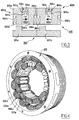
figure 4 montre en perspective le stator selon le mode de réalisation préféré de l'invention, - la
figure 5 montre une vue agrandie du stator de lafigure 4 , - la
figure 6 , montre schématiquement une vue en plan, et selon la direction de l'axe de rotation du rotor, la machine selon le mode de réalisation préféré de l'invention, - la
figure 7 illustre les flux magnétiques impliqués dans des cellules lorsque le courant d'excitation est sensiblement nul, - la
figure 8 illustre les flux magnétiques impliqués dans ces cellules lorsque le courant d'excitation est positif, - la
figure 9 illustre les flux magnétiques impliqués dans ces cellules lorsque le courant d'excitation est négatif, - la
figure 10 montre graphiquement à titre d'exemple non limitatif l'amplitude du flux de la machine selon l'invention avec et sans aimant permanent dans le stator, et ce en fonction d'un courant d'excitation fourni dans les bobinages d'excitation, et - la
figure 11 , montre graphiquement à titre d'exemple non limitatif le couple de la machine en fonction d'un angle électrique, dans les conditions où le stator comporte les bobinages d'excitation seulement, les aimants permanents seulement, ou la combinaison des bobinages et des aimants précités.
- the
figure 1 already commented, schematically shows a rotating machine with double excitation switching of the state of the art, - the
figure 2 schematically illustrates a rotating machine according to the invention with its elementary cells distributed around the rotor along a perimeter of the stator, - the
figure 3 , schematically shows in plan and seen in a direction parallel to the axis of rotation of the rotor, two cells arranged according to a preferred embodiment of the invention, - the
figure 4 shows in perspective the stator according to the preferred embodiment of the invention, - the
figure 5 shows an enlarged view of the stator of thefigure 4 , - the
figure 6 schematically shows a plan view, and in the direction of the axis of rotation of the rotor, the machine according to the preferred embodiment of the invention, - the
figure 7 illustrates the magnetic fluxes involved in cells when the excitation current is substantially zero, - the
figure 8 illustrates the magnetic fluxes involved in these cells when the excitation current is positive, - the
figure 9 illustrates the magnetic fluxes involved in these cells when the excitation current is negative, - the
figure 10 shows graphically by way of nonlimiting example the amplitude of the flow of the machine according to the invention with and without permanent magnet in the stator, and this as a function of an excitation current supplied in the excitation windings, and - the
figure 11 , shows graphically by way of nonlimiting example the torque of the machine as a function of an electric angle, under the conditions where the stator comprises the excitation windings only, the permanent magnets only, or the combination of the windings and magnets supra.
En se référant à la
La machine comporte un rotor 101 muni d'une pluralité de dents 104 et entouré par un stator 102.The machine comprises a
Le stator comporte, à titre d'exemple non limitatif, six cellules élémentaires 103a à 103f distribuées suivant le périmètre du stator et donc autour du rotor.The stator comprises, by way of nonlimiting example, six elementary cells 103a to 103f distributed along the perimeter of the stator and thus around the rotor.
Par principe, dans ce texte, chaque cellule est définie comme étant apte à interagir avec une seule parmi lesdites dents du rotor 101.In principle, in this text, each cell is defined as being able to interact with only one of said teeth of the
Par exemple, on voit que dans la configuration angulaire du rotor présentée à la
Chaque cellule élémentaire 103 comporte un aimant permanent Ai et une première encoche pour loger au moins en partie un ou plusieurs bobinages d'excitation Ei.Each
Un tel agencement permet facilement qu'au sein d'une même cellule les champs magnétiques générés par l'aimant Ai et le bobinage d'excitation Ei se compensent localement.Such an arrangement easily allows that within the same cell the magnetic fields generated by the magnet Ai and the excitation coil Ei compensate locally.
Ainsi, de manière avantageuse, il est possible très simplement de réduire les pertes électromagnétiques de la machine.Thus, advantageously, it is possible very simply to reduce the electromagnetic losses of the machine.
En effet, dans chacune des cellules les champs peuvent avoir une amplitude très grande, mais la résultante au sein de celle-ci peut être réduite par un agencement approprié dudit aimant et dudit bobinage.Indeed, in each of the cells the fields can have a very large amplitude, but the resultant within it can be reduced by an appropriate arrangement of said magnet and said coil.
A titre d'exemple non limitatif, si l'on suppose que ce dernier génère un premier champ de 1,0 Teslas en sens opposé à un deuxième champ de 1,5 Teslas généré par l'aimant, la résultante au sein de la cellule est de 0,5 Teslas dans le sens du deuxième champ.By way of non-limiting example, if it is assumed that the latter generates a first field of 1.0 Tesla opposite to a second field of 1.5 Tesla generated by the magnet, the resultant within the cell is 0.5 Tesla in the direction of the second field.
Au contraire, dans un agencement où chaque cellule ne comporte pas la combinaison de l'aimant et du bobinage d'excitation, et en particulier si la cellule comporte l'aimant Ai et sa cellule adjacente le bobinage Ei, le champ résultant au sein de chaque cellule est maximal, à savoir égale à celui généré par le moyen actif dans la cellule en question (d'un côté le champ généré par l'aimant permanent Ai, de l'autre celui par le bobinage Ei).On the contrary, in an arrangement where each cell does not have the combination of the magnet and the excitation coil, and in particular if the cell comprises the magnet Ai and its adjacent cell the coil Ei, the resulting field within each cell is maximal, namely equal to that generated by the active means in the cell in question (on one side the field generated by the permanent magnet Ai, on the other that by the winding Ei).
Ainsi dans une telle machine, les pertes sont importantes.Thus in such a machine, the losses are important.
On va maintenant décrire plus en détails un mode de réalisation préféré de l'invention.A preferred embodiment of the invention will now be described in more detail.
A cet égard on se référera d'abord à la
Plus précisément on peut y voir deux dents 301a et 301b d'un rotor 300 interagissant avec deux cellules élémentaires 400a et 400b d'un stator 400, respectivement.More precisely, there can be seen two
Chaque dent est en regard d'une région de la cellule correspondante qui se situe à une distance du centre de rotation du rotor la plus proche.Each tooth is facing a region of the corresponding cell which is at a distance from the center of rotation of the nearest rotor.
En considérant maintenant, à titre d'exemple non limitatif, la cellule élémentaires 400a, celle-ci comporte une encoche 500a pour loger une partie 501a et 502a de deux bobinages d'excitation 501 et 502.Considering now, by way of nonlimiting example, the
Ces parties 501a et 502a sont logées respectivement à gauche et à droite de l'encoche lorsque l'on considère le sens des aiguilles d'une montre par rapport à l'axe de rotation du rotor ou de la machine.These
Les brins de ces bobinages sont aptes à être parcourus par un courant dirigé dans le sens désigné par le symbole Sa.The strands of these windings are able to be traversed by a current directed in the direction indicated by the symbol Sa.
Tel que représenté dans cette cellule, le courant dans les deux parties de bobinage 501a et 502a est donc censé sortir de l'encoche par le haut du plan de la figure.As shown in this cell, the current in the two winding
Bien entendu, ceci n'exclut par le fait que les courants dans ces bobinages puissent dans une autre représentation liée à une autre condition de fonctionnement de la machine être dirigés en sens inverse, par exemple.Of course, this does not exclude the fact that the currents in these coils can in another representation linked to another machine operating condition be directed in the opposite direction, for example.
Dans la cellule adjacente 400b, on a également prévu une encoche 500b pour loger une autre partie de l'un des bobinages précédents.In the
En particulier, la cellule 400b étant située à droite de la cellule 400a, l'encoche 500b loge une autre partie 502b du bobinage 502, car comme indiqué précédemment ce bobinage étant logé à droite de l'encoche 500a, le trajet entre les parties gauche et droite des encoches respectives 500a et 500b est le plus court.In particular, since the
Bien entendu, le bobinage 501 dans la cellule 400a possède une autre partie dans l'encoche d'une autre cellule adjacente non représentée.Of course, the winding 501 in the
Plus précisément, ce bobinage 501 étant logé à gauche dans l'encoche 500a ladite autre partie est naturellement logée dans l'encoche de la cellule directement adjacente à gauche (non représentée).More specifically, this winding 501 being housed on the left in the
Cette remarque vaut également pour la cellule adjacente à droite de la cellule 400b et ainsi de suite.This remark also applies to the cell adjacent to the right of the
En particulier, l'encoche 500b loge dans sa région gauche la partie 502b du bobinage 502 et, dans sa région droite, une partie 503b d'un autre bobinage 503, cette autre partie de ce dernier étant logée, à son tour, dans la région gauche de l'encoche d'une cellule (non représentée) qui se trouve deux fois à droite de la cellule 400b.In particular, the
On remarquera d'après la
En plus de l'encoche 500a, la cellule 400a comporte une encoche pour loger un aimant permanent 600a.In addition to the
Cette encoche et l'encoche 500a sont alignées dans une direction radiale par rapport au centre du rotor.This notch and
De préférence, ces deux encoches sont disposées adjacentes dans cette direction.Preferably, these two notches are arranged adjacent in this direction.
Par ailleurs, la somme de leur hauteur respective (dans la direction radiale) est presque égale à la hauteur de la cellule.Moreover, the sum of their respective height (in the radial direction) is almost equal to the height of the cell.
Cette dernière hauteur est en fait sensiblement plus grande du fait de la présence dans ledit alignement radial d'un premier matériau ferromagnétique 700a d'une hauteur e.This latter height is actually substantially larger because of the presence in said radial alignment of a first
On parlera par la suite de cette hauteur e en la désignant par l'épaisseur e.We will speak later of this height e by designating it by the thickness e.
Plus précisément, ce matériau est adjacent à l'encoche 500a du bobinage d'excitation 501 et 502 de sorte à amplifier de manière contrôlée une force magnétique de ce bobinage lorsqu'il est parcouru par le courant.More specifically, this material is adjacent to the
Le contrôle de cette force est rendu possible en jouant notamment sur l'épaisseur e.The control of this force is made possible by playing in particular on the thickness e.
Ainsi, au moment de la conception de la machine on déterminera cette épaisseur e en fonction d'autres éléments de la cellule et selon une valeur minimale choisie de la force souhaitée.Thus, at the time of designing the machine, this thickness e will be determined as a function of other elements of the cell and according to a chosen minimum value of the desired force.
L'ensemble constitué par l'encoche 500a, l'aimant 600a et le premier matériau s'étendent dans ladite direction radiale sensiblement au centre de la cellule 400a.The assembly constituted by the
De part et d'autre de cet ensemble, c'est-à-dire à gauche et à droite, on a prévu deux deuxièmes matériaux ferromagnétiques 800a et 801a.On either side of this assembly, that is to say on the left and on the right, two second
Ceux-ci sont solidaires du premier matériau 700a et de préférence ils sont tous trois d'un seul bloc.These are integral with the
Un avantage est que par construction simple de ces trois matériaux en particulier le stator de l'invention possède une très bonne rigidité.One advantage is that by simple construction of these three materials in particular the stator of the invention has a very good rigidity.
Par ailleurs, le premier et les deuxièmes matériaux forment sensiblement un U tourné vers le bas.In addition, the first and second materials substantially form a U facing downwards.
C'est dans l'ouverture du U que l'on dispose les deux parties des deux bobinages d'excitation et l'aimant permanent.It is in the opening of the U that the two parts of the two excitation coils and the permanent magnet are arranged.
Les deuxièmes matériaux comportent chacun une deuxième encoche 802a et 803a pour loger un bobinage d'induit 900a.The second materials each include a
Ces encoches, de forme identique, sont disposées symétriquement par rapport à un axe radial, de part et d'autre de l'aimant permanent.These notches, of identical shape, are arranged symmetrically with respect to a radial axis, on either side of the permanent magnet.
En particulier, elles sont agencées dans un décrochement prévu dans les deuxièmes matériaux.In particular, they are arranged in a recess provided in the second materials.
En outre, elles sont agencées de telle sorte que le bobinage 900a puisse entourer cet aimant.In addition, they are arranged in such a way that the winding 900a can surround this magnet.
Ainsi à titre d'exemple, le bobinage d'induit 900a peut être enroulé vers le dessous du plan de la figure, dans l'encoche 802a située à gauche de l'ensemble, et vers le haut dans l'encoche 802a située à droite dudit ensemble.Thus for example, the armature winding 900a can be wound to the underside of the plane of the figure, in the notch 802a located to the left of the assembly, and upwards in the notch 802a on the right said set.
Et la liaison entre ces deux encoches est définie par deux têtes de bobinage non représentées, où les brins sont enroulés respectivement vers la gauche et vers la droite pour passer devant les deuxièmes matériaux et l'aimant permanent 600a.And the connection between these two notches is defined by two winding heads not shown, where the strands are wound respectively to the left and to the right to pass in front of the second materials and the
On notera que ces têtes plus les deux parties d'un bobinage d'excitation logées dans deux encoches forment un bobinage complet.Note that these heads plus the two parts of an excitation coil housed in two notches form a complete winding.
On notera aussi que, de préférence, la hauteur des encoches 802a et 803a est sensiblement égale à celle de l'aimant permanent 600a.It will also be noted that, preferably, the height of the
Par ailleurs, toujours selon le mode préféré de l'invention, la deuxième encoche 803a communique avec la deuxième encoche située à gauche dans la cellule 400b.Furthermore, still according to the preferred embodiment of the invention, the
Ce principe de communication s'applique également à la deuxième encoche 802a avec l'encoche qui est à droite dans la cellule non représentée qui se trouve à gauche de ladite cellule 400a.This communication principle also applies to the second notch 802a with the notch which is to the right in the not shown cell which is to the left of said
En référence aux
On peut voir en particulier, sur les
- des bobinages dans chaque cellule d'induit et d'excitation, et
- des encoches d'aimants dans chaque cellule.
- coils in each armature and excitation cell, and
- notches of magnets in each cell.
Par ailleurs, sur ces figures et en particulier sur la
On peut voir également de façon plus détaillée que sur la
On peut voir en outre l'agencement des trois phases P1 à P3 nécessaires à la machine de type triphasé présentée ici à titre d'exemple non limitatif.We can also see the arrangement of the three phases P1 to P3 required for the three-phase machine presented here by way of non-limiting example.
On va maintenant décrire le fonctionnement de la machine réalisée selon le mode préféré de l'invention.We will now describe the operation of the machine made according to the preferred embodiment of the invention.
A titre préliminaire, le fonctionnement du rotor avec le stator ne sera pas décrit en détails dans la mesure où ce fonctionnement est classique et connu en soi dans les machines à commutation de flux.As a preliminary, the operation of the rotor with the stator will not be described in detail insofar as this operation is conventional and known per se in flux-commutated machines.
Ainsi, on notera simplement pour la compréhension du texte qui suit, que le stator étant fixe, le rotor est, lui, amené à tourner autour de son axe par le biais d'une variation contrôlée des champs magnétiques dans le stator et des courants dans les bobinages d'induit au stator.Thus, it will be noted simply for the understanding of the text that follows, that the stator being fixed, the rotor is itself rotated about its axis through a controlled variation of the magnetic fields in the stator and currents in armature windings to the stator.
La
Par ailleurs, il est important de noter que cette figure illustre ces flux lorsque les courants d'excitation dans les bobinages d'excitation sont inférieurs à une valeur seuil prédéterminée et lorsque, ainsi, les champs magnétiques engendrés par ces bobinages sont négligeables par rapport à ceux générés par les aimants permanents.Moreover, it is important to note that this figure illustrates these fluxes when the excitation currents in the excitation windings are lower than a predetermined threshold value and when, thus, the magnetic fields generated by these windings are negligible compared to those generated by permanent magnets.
En considérant à titre d'exemple non limitatif la cellule 400a, le champ magnétique de l'aimant permanent 600a est noté B1.By considering as a non-limiting example the
Au niveau de cet aimant, les lignes de flux s'étendent suivant le périmètre du stator, et ce, de gauche à droite dans cet exemple.At the level of this magnet, the flux lines extend along the perimeter of the stator, from left to right in this example.
On voit en outre que les aimants permanents dans la machine ont été agencés de telle sorte que le champ B1 dans une cellule est orienté en sens opposé aux champs respectifs B1 dans les deux cellules adjacentes à la cellule en question.It is further seen that the permanent magnets in the machine have been arranged so that the field B1 in a cell is oriented in a direction opposite the respective fields B1 in the two cells adjacent to the cell in question.
Par exemple dans la cellule 400a, le champ B1 est orienté au niveau de l'aimant dans le sens des aiguilles d'une montre, tandis que dans les cellules adjacentes, par exemple dans la cellule 400b, le champ est orienté dans le sens trigonométrique.For example, in
Dans la configuration angulaire du rotor présenté à titre d'exemple non limitatif sur la
Il passe donc à travers le premier matériau 700a puis à travers le deuxième matériau 800a.It passes through the
Une autre partie des lignes de champ, en particulier une partie située sensiblement à équidistance de l'encoche 501a et de la dent 301a du rotor, traverse l'aimant permanent dans le sens des aiguilles d'une montre suivant ledit périmètre et tend à rejoindre le parcours décrit ci-dessus.Another portion of the field lines, in particular a portion located substantially equidistant from the
Par ailleurs, les lignes qui traversent l'aimant proviennent de la dent 301a du rotor.In addition, the lines passing through the magnet come from the
Elles correspondent à des lignes de champs qui sont associées à au moins l'une des cellules adjacentes et qui passent par le rotor.They correspond to lines of fields which are associated with at least one of the adjacent cells and which pass through the rotor.
En particulier, selon cette configuration angulaire, certaines de ces lignes proviennent de l'aimant permanent de la cellule à gauche, d'autres de l'aimant permanent de la cellule à droite.In particular, according to this angular configuration, some of these lines come from the permanent magnet of the cell on the left, others from the permanent magnet of the cell on the right.
On notera que ces lignes peuvent aussi correspondre à certaines parmi celles qui seront décrites ci-après.Note that these lines may also correspond to some of those which will be described below.
Une dernière partie des lignes de champ, en particulier une partie qui est la plus proche de la dent 301a, traverse l'aimant permanent dans le sens des aiguilles d'une montre et parcourt le deuxième matériau 801a en se dirigeant cette fois-ci vers le rotor.A last part of the field lines, in particular a part which is the closest to the
Dans cette configuration angulaire, la dent 301b, en regard alors de la cellule 400b, est à une distance de l'aimant telle que certaines parmi ces dernières lignes de champ (mais dans cet exemple une faible proportion seulement) peuvent parcourir cette dent 301b, la périphérie du rotor, et ressortir de ce dernier pas la dent 301a pour reboucler au niveau de l'aimant permanent 600a.In this angular configuration, the
Toutefois, dans cette configuration encore, une grande proportion de ces lignes reboucle localement sur l'aimant permanent sans passer par le rotor.However, in this configuration again, a large proportion of these lines loops locally on the permanent magnet without passing through the rotor.
Bien entendu, la description ci-dessus n'est pas exhaustive et sert plutôt d'illustration.Of course, the above description is not exhaustive and is rather illustrative.
L'homme du métier comprendra en particulier que, de part les phénomènes physiques impliqués, il serait vain et sans doute fort peu utile d'essayer de décrire de façon extrêmement précise tous les flux présents dans la machine.Those skilled in the art will understand in particular that, because of the physical phenomena involved, it would be futile and probably not very useful to try to describe in an extremely precise manner all the flows present in the machine.
La
On entend par courant positif un courant orienté dans un sens tel que le champs électromagnétique engendré par le bobinage d'excitation s'ajoute au moins en partie au champ de l'aimant permanent de sorte à accroître le flux dans les bobinages d'induit.By positive current is meant a current oriented in a direction such that the electromagnetic field generated by the excitation coil is added at least in part to the field of the permanent magnet so as to increase the flux in the armature windings.
Dans ce cas, et dans la configuration angulaire précitée du rotor, la plupart des lignes de champs traversant l'aimant permanent viennent de la dent 301a.In this case, and in the aforementioned angular configuration of the rotor, most field lines passing through the permanent magnet come from the
Et plus précisément, ces lignes peuvent provenir des aimants permanents des deux cellules adjacentes après avoir traversées le rotor et en particulier les dents en regard de ces deux cellules.And more specifically, these lines can come from the permanent magnets of the two adjacent cells after passing through the rotor and in particular the teeth opposite these two cells.
De l'autre côté de l'aimant permanent, une partie des lignes de champs se propage dans le premier matériau 700b de la cellule 400b pour reboucler sur l'aimant 600b, après avoir contournée en partie l'encoche 500b.On the other side of the permanent magnet, part of the field lines is propagated in the first material 700b of the
Et l'autre partie de ces lignes contourne par la droite l'encoche 500a en passant notamment dans le premier matériau 700a, puis se propage dans la cellule adjacente à gauche en direction de son aimant permanent.And the other part of these lines bypasses the
Il existe ainsi principalement un bouclage défini successivement par l'aimant 600a, le premier matériau 700b, l'aimant 600b, la dent 301b et la dent 301a.There is thus mainly a looping defined successively by the
Et il existe un autre bouclage avec l'aimant 600a, le premier matériau 700a, l'aimant de la cellule à gauche, la dent en regard de cette dernière et la dent 301a.And there is another loopback with the
En référence à la
Dans ce cas, la plupart des flux ne passent plus par le rotor et en particulier par ses dents.In this case, most flows no longer pass through the rotor and in particular through its teeth.
Et les flux rebouclent à l'intérieur d'une même cellule sans passer par une autre cellule.And streams loop back inside the same cell without going through another cell.
Plus précisément, les flux dans une cellule forment une seule boucle à l'intérieure de celle-ci, passant en particulier par l'aimant permanent (par exemple 600a), contournant l'encoche de bobinage d'excitation à travers notamment le premier matériau (par exemple 700a dans le sens trigonométrique) pour revenir finalement sur l'aimant.More specifically, the flows in a cell form a single loop inside thereof, passing in particular by the permanent magnet (for example 600a), bypassing the excitation coil notch through in particular the first material (eg 700a in the trigonometrical direction) to finally return to the magnet.
Comme l'aura compris l'homme du métier, les flux magnétiques décrits à partir des
En particulier, lorsqu'un courant négatif parcourt les bobinages d'excitation, le flux magnétique dans les bobinages d'induit a tendance à s'annuler, tandis que lorsque ce courant est positif, il a tendance au contraire à augmenter.In particular, when a negative current flows through the excitation windings, the magnetic flux in the armature windings tends to cancel out, whereas when this current is positive, it tends on the contrary to increase.
En référence à la
Afin d'illustrer par ailleurs un intérêt de la combinaison d'un aimant permanent avec un bobinage d'excitation, cette figure comporte une première courbe 1200 qui correspond à la machine dépourvue d'aimant permanent dans chacune des cellules, et une deuxième courbe 1100 qui correspond à la machine réalisée selon le mode préféré de l'invention.In order to further illustrate an interest in the combination of a permanent magnet with an excitation winding, this figure includes a
On notera ici que les valeurs des coordonnées sur les axes ne sont à considérer qu'à titre indicatif seulement.It should be noted here that the values of the coordinates on the axes are to be considered for information only.
Comme on peut le voir, l'amplitude des flux sur la courbe 1100 est toujours supérieure à celle sur la courbe 1200, ce qui montre une amélioration des performances de la machine, notamment en termes de couple.As can be seen, the amplitude of the flows on the
A cet égard, sur la
Dans le premier cas illustré par la courbe 1500, la machine fonctionne grâce aux bobinages d'excitation seulement, c'est-à-dire que les aimants permanents ne sont pas actifs, et ceux dans les bobinages d'induit sont alternatifs, fonction de la position angulaire du rotor.In the first case illustrated by the
Dans le deuxième cas illustré par la courbe 1400, seuls les aimants permanents sont actifs, c'est-à-dire que le courant dans le bobinage d'excitation est négligeable ou nul. Le couple pour faire tourner le rotor de la machine est créé par l'interaction des courants dans les bobinages d'induit et des flux dus aux aimants permanents.In the second case illustrated by the
Enfin, dans le troisième cas illustré par la courbe 1300, on combine l'action des aimants permanents, des bobinages d'excitation et des bobinages d'induit.Finally, in the third case illustrated by
Comme on pouvait s'y attendre, la combinaison des moyens actifs précités offre un meilleur couple.As might be expected, the combination of the aforementioned active means provides a better pair.
Plus précisément encore, on peut constater que, contrairement à toute attente et à la surprise de la demanderesse, la courbe 1300 est supérieure à une simple superposition des courbes 1400 et 1500.More precisely, it can be seen that, contrary to all expectations and to the plaintiff's surprise, the
En d'autres termes, la machine selon le mode préféré de l'invention bénéficie d'effets de synergie avantageux qui lui confère des performances en couple bien supérieures à une simple addition des couples obtenus pour les premier et deuxième cas susmentionnés.In other words, the machine according to the preferred embodiment of the invention benefits from advantageous synergistic effects which gives it a much higher torque performance than a simple addition of the torques obtained for the first and second cases mentioned above.
A cet égard, la demanderesse pense que, la compensation locale dans chaque cellule du champ magnétique susmentionnée contribue dans une certaine mesure à un tel effet.In this regard, the applicant believes that the local compensation in each cell of the aforementioned magnetic field contributes to a certain extent to such an effect.
Bien entendu, la présente invention n'est nullement limitée à la forme de réalisation décrite ci-dessus et représentée sur les dessins.Of course, the present invention is not limited to the embodiment described above and shown in the drawings.
En particulier, on peut selon une variante du mode de réalisé présenté jusqu'ici disposer les éléments différemment au sein d'une cellule.In particular, it is possible, according to a variant of the embodiment presented heretofore, to arrange the elements differently within a cell.
Par exemple, on peut intervertir les positions de l'encoche 500a du bobinage d'excitation et de l'encoche 600a de l'aimant permanent, de sorte que ce dernier se retrouve finalement le plus éloigné du rotor.For example, the positions of the
On notera alors que le deuxième matériau 700a devra être disposé de préférence sur la périphérie interne de la cellule, c'est-à-dire à son extrémité basse vu du centre de rotation, ou encore entre la dent du rotor et l'encoche 500a.Note then that the
Selon une autre variante, on pourra utiliser des cellules agencées selon le mode préféré de l'invention, et d'autres cellules agencées selon la variante précédente.According to another variant, it is possible to use cells arranged according to the preferred embodiment of the invention, and other cells arranged according to the preceding variant.
Selon une autre variante, on logera dans l'encoche 500a une partie d'un unique bobinage d'excitation (et non deux parties de deux bobinages selon le mode préféré).According to another variant, a part of a single excitation winding (and not two parts of two windings according to the preferred embodiment) will be housed in the
Et une autre partie de ce bobinage sera logée exclusivement dans l'encoche 500b de la cellule adjacente 400b.And another part of this winding will be housed exclusively in the
Selon une autre variante encore, on isolera les encoches 900a de bobinage d'induit qui sont adjacentes entre deux cellules.According to yet another variant, the
Au vu de ce qui précède, les avantages de la présente invention sont faciles à percevoir, certains ayant d'ailleurs déjà été présentés.In view of the above, the advantages of the present invention are easy to perceive, some have already been presented.
En ce qui concerne en particulier la facilité de fabrication et l'encombrement, il apparaît clairement d'après la description et en particulier d'après les dessins que ces aspects sont nettement améliorés.Particularly with regard to ease of manufacture and bulk, it is clear from the description and in particular from the drawings that these aspects are markedly improved.
Un telle amélioration est notamment due aux agencements des bobinages les uns vis-à-vis des autres, en particulier aux croisements limités entre les différents brins et à l'utilisation du premier matériau en tant qu'élément impliqué à la fois dans les performances électriques et mécaniques (rigidité, etc.) de la machine.Such an improvement is due in particular to the arrangement of the windings vis-à-vis each other, in particular to limited crossings between the different strands and the use of the first material as an element involved both in the electrical performance and mechanical (rigidity, etc.) of the machine.
Claims (11)
- A flux switching electrical machine including a stator (400) and a rotor (300), the stator including permanent magnets (600a, 600b), armature windings (900a, 900b) and excitation windings (501, 502), and the rotor not having any windings or permanent magnet, and including a plurality of flux switching teeth (301a, 301b), characterized in that the stator is generally formed by a succession of elementary cells (400a, 400b), each (400a) intended to interact with a single tooth of the rotor at a time, and each comprising:- one of the permanent magnets (600a),- a first slot (500a) to at least partly house at least one (501a) of the excitation windings (501) and;- second slots (802a, 803a) to house one (900a) of the armature windings.
- The machine according to claim 1, characterized in that, in each cell (400a), the permanent magnet (600a) and the first slot (500a) are aligned along a radial direction.
- The machine according to one of the preceding claims, characterized in that, in each cell, the excitation windings and the permanent magnet are arranged in the same first slot (500a).
- The machine according to one of the preceding claims, characterized in that, in each cell (400a), the second slots (802a, 803a) are at a substantially equal radial distance from an axis of rotation of the rotor (300).
- The machine according to one of the preceding claims, characterized in that the second slots (802a, 803a) extend on either side of the permanent magnet (600a).
- The machine according to one of the preceding claims, characterized in that each elementary cell further comprises a first material forming a portion of the magnetic circuit (700a) located at the periphery of the stator and provided for at least partially enclosing a flux (B1) generated by the excitation windings and/or the permanent magnets.
- The machine according to claim 6, characterized in that the first material forming a portion of the magnetic circuit (700a) has a thickness e such that the magnetic force of the excitation winding(s) (501a, 502a) is greater than or equal to a predetermined threshold value.
- The machine according to one of the preceding claims, characterized in that each cell (400a) further includes at least one second ferromagnetic material (800a, 801a) separating the permanent magnet (600a) from the winding of the armature (900a).
- The machine according to one of claims 6 to 7, characterized in that the first (700a) and second materials (800a, 801a) are in a single-piece and substantially form a U turned towards the axis of rotation of the rotor (300).
- The machine according to one of the previous claims, characterized in that in each cell (400a), the permanent magnet (600a) and the first slot (500a) generally form a T, as seen from the axis of rotation of the rotor (300).
- The machine according to one of the previous claims, characterized in that the excitation windings are subdivided in the first slots of two adjacent elementary cells.
Applications Claiming Priority (2)
| Application Number | Priority Date | Filing Date | Title |
|---|---|---|---|
| FR0602058A FR2898439B1 (en) | 2006-03-08 | 2006-03-08 | ELECTRIC MACHINE WITH FLOW SWITCHING AND DOUBLE EXCITATION |
| PCT/EP2007/052167 WO2007101876A1 (en) | 2006-03-08 | 2007-03-08 | Flux-switching dual-excitation electrical machine |
Publications (2)
| Publication Number | Publication Date |
|---|---|
| EP2002529A1 EP2002529A1 (en) | 2008-12-17 |
| EP2002529B1 true EP2002529B1 (en) | 2011-05-04 |
Family
ID=37103147
Family Applications (1)
| Application Number | Title | Priority Date | Filing Date |
|---|---|---|---|
| EP07726708A Not-in-force EP2002529B1 (en) | 2006-03-08 | 2007-03-08 | Flux-switching dual-excitation electrical machine |
Country Status (7)
| Country | Link |
|---|---|
| US (1) | US7868506B2 (en) |
| EP (1) | EP2002529B1 (en) |
| AT (1) | ATE508519T1 (en) |
| DE (1) | DE602007014346D1 (en) |
| ES (1) | ES2366055T3 (en) |
| FR (1) | FR2898439B1 (en) |
| WO (1) | WO2007101876A1 (en) |
Cited By (2)
| Publication number | Priority date | Publication date | Assignee | Title |
|---|---|---|---|---|
| DE102011121174A1 (en) | 2011-12-16 | 2013-06-20 | Eads Deutschland Gmbh | Electric machine, in particular for aircraft |
| US20230052512A1 (en) * | 2020-02-07 | 2023-02-16 | Martin Hugh Boughtwood | Motor/generator |
Families Citing this family (26)
| Publication number | Priority date | Publication date | Assignee | Title |
|---|---|---|---|---|
| US7710081B2 (en) * | 2006-10-27 | 2010-05-04 | Direct Drive Systems, Inc. | Electromechanical energy conversion systems |
| GB2468695B (en) * | 2009-03-18 | 2011-02-09 | Imra Europ S A S Uk Res Ct | An electrical machine |
| CN101834474A (en) * | 2010-03-17 | 2010-09-15 | 常州工学院 | Multitooth magnetic bridge type hybrid excitation magnetic flux switching motor |
| FR2982716B1 (en) * | 2011-11-10 | 2013-12-20 | Leroy Somer Moteurs | FLOW SWITCHING MACHINE |
| FR2982714B1 (en) | 2011-11-10 | 2013-12-20 | Leroy Somer Moteurs | ELECTRIC FLOW-SWITCHING MACHINE |
| CN102570656A (en) * | 2012-01-04 | 2012-07-11 | 东风汽车零部件(集团)有限公司 | Electric-excitation brushless starter generator (motor) |
| JP5798072B2 (en) * | 2012-03-26 | 2015-10-21 | 株式会社デンソー | Rotating machine |
| US9236784B2 (en) | 2012-03-30 | 2016-01-12 | General Electric Company | Flux-switching electric machine |
| JP5696694B2 (en) * | 2012-08-01 | 2015-04-08 | トヨタ自動車株式会社 | Rotating electric machine stator |
| CN103051138B (en) * | 2012-12-20 | 2015-04-15 | 东南大学 | Multi-tooth magnetic flux switching permanent magnetic memory motor |
| CN103051139B (en) * | 2012-12-20 | 2015-04-15 | 东南大学 | Magnetic flux switching type permanent magnet memory motor |
| JP6093592B2 (en) * | 2013-02-22 | 2017-03-08 | 株式会社Ihi | Magnetic wave gear device |
| CN103490573B (en) * | 2013-09-18 | 2015-11-18 | 东南大学 | A kind of axial magnetic field Magneticflux-switching type surface-mount type permanent magnetism memory electrical machine |
| CN103490575B (en) * | 2013-10-17 | 2016-03-30 | 东南大学 | Multiple tooth mixing exciter panel type wind-driven generator |
| CN104113150B (en) * | 2014-07-18 | 2017-08-01 | 西安交通大学 | A kind of multiple tooth stator core hybrid excitation switched flux motor of combined type |
| JP2016032385A (en) | 2014-07-30 | 2016-03-07 | ダイキン工業株式会社 | Motor |
| US10020717B2 (en) * | 2014-08-13 | 2018-07-10 | Wisconsin Alumni Research Foundation | Dual stator, flux switching permanent magnet machine |
| JP6450588B2 (en) * | 2014-12-26 | 2019-01-09 | ダイキン工業株式会社 | Rotating electrical machine |
| JP6139007B2 (en) * | 2015-09-25 | 2017-05-31 | ダイキン工業株式会社 | Rotating electrical machine |
| WO2018117195A1 (en) * | 2016-12-20 | 2018-06-28 | ダイキン工業株式会社 | Rotary electric machine |
| CN108696013A (en) * | 2017-04-07 | 2018-10-23 | 章宪 | AC magnetoelectric machine |
| US9882438B1 (en) * | 2017-07-25 | 2018-01-30 | Chad Ashley Vandenberg | Generators having rotors that provide alternate magnetic circuits |
| CN110518766B (en) * | 2018-05-22 | 2021-02-12 | 南京理工大学 | Asymmetric double-stator mixed excitation type axial magnetic field flux switching motor |
| FR3105885B1 (en) | 2019-12-26 | 2021-11-26 | Thales Sa | Two-stage electric drive system |
| CN114982107A (en) * | 2020-01-21 | 2022-08-30 | 三菱电机株式会社 | Stator and rotating electric machine using the same |
| US20230026553A1 (en) * | 2020-01-21 | 2023-01-26 | Mitsubishi Electric Corporation | Stator and rotary electric machine using same |
Family Cites Families (13)
| Publication number | Priority date | Publication date | Assignee | Title |
|---|---|---|---|---|
| US3439200A (en) * | 1966-01-18 | 1969-04-15 | Yokogawa Electric Works Ltd | Reversible stepping motor with braking coils and biasing permanent magnets |
| DE2310948C3 (en) * | 1973-03-05 | 1978-12-14 | Siemens Ag, 1000 Berlin Und 8000 Muenchen | Stand for machines with permanent magnet excitation |
| DE2460630B2 (en) * | 1974-12-20 | 1976-09-30 | Siemens AG, 1000 Berlin und 8000 München | PERMANENT MAGNETIC DIRECT CURRENT MACHINE |
| US3984711A (en) * | 1975-04-07 | 1976-10-05 | Warner Electric Brake & Clutch Company | Variable reluctance step motor with permanent magnets |
| DE58904848D1 (en) * | 1989-04-27 | 1993-08-05 | Siemens Ag | HETEROPOLAR EXCITED SYNCHRONOUS MACHINE. |
| US5825112A (en) * | 1992-08-06 | 1998-10-20 | Electric Power Research Institute, Inc. | Doubly salient motor with stationary permanent magnets |
| US5672925A (en) * | 1992-08-06 | 1997-09-30 | Electric Power Research Institute, Inc. | Doubly salient variable reluctance machine with stationary permanent magnets or auxiliary field windings |
| SE516499C2 (en) * | 1996-05-30 | 2002-01-22 | Vilmos Toeroek | Self-starting brushless electric motor |
| FR2762158B1 (en) * | 1997-04-14 | 1999-06-25 | Valeo Equip Electr Moteur | POLYPHASE BRUSHED MACHINE, ESPECIALLY A MOTOR VEHICLE ALTERNATOR |
| FR2769422B1 (en) * | 1997-10-07 | 1999-12-24 | Valeo Equip Electr Moteur | ELECTRIC FLOW SWITCHING MACHINE, IN PARTICULAR A MOTOR VEHICLE ALTERNATOR |
| US6246561B1 (en) * | 1998-07-31 | 2001-06-12 | Magnetic Revolutions Limited, L.L.C | Methods for controlling the path of magnetic flux from a permanent magnet and devices incorporating the same |
| JP2001041238A (en) * | 1999-07-28 | 2001-02-13 | Seiko Seiki Co Ltd | Composite type electromagnet and radial magnetic bearing |
| KR100442122B1 (en) * | 2001-07-31 | 2004-07-30 | 한국전기연구원 | Brushless generator with permanent magnet |
-
2006
- 2006-03-08 FR FR0602058A patent/FR2898439B1/en not_active Expired - Fee Related
-
2007
- 2007-03-08 DE DE602007014346T patent/DE602007014346D1/en active Active
- 2007-03-08 WO PCT/EP2007/052167 patent/WO2007101876A1/en active Application Filing
- 2007-03-08 US US12/299,002 patent/US7868506B2/en not_active Expired - Fee Related
- 2007-03-08 EP EP07726708A patent/EP2002529B1/en not_active Not-in-force
- 2007-03-08 AT AT07726708T patent/ATE508519T1/en not_active IP Right Cessation
- 2007-03-08 ES ES07726708T patent/ES2366055T3/en active Active
Cited By (3)
| Publication number | Priority date | Publication date | Assignee | Title |
|---|---|---|---|---|
| DE102011121174A1 (en) | 2011-12-16 | 2013-06-20 | Eads Deutschland Gmbh | Electric machine, in particular for aircraft |
| DE102011121174B4 (en) * | 2011-12-16 | 2014-04-03 | Eads Deutschland Gmbh | Electric machine, in particular for aircraft |
| US20230052512A1 (en) * | 2020-02-07 | 2023-02-16 | Martin Hugh Boughtwood | Motor/generator |
Also Published As
| Publication number | Publication date |
|---|---|
| ES2366055T3 (en) | 2011-10-14 |
| ATE508519T1 (en) | 2011-05-15 |
| US20100038978A1 (en) | 2010-02-18 |
| EP2002529A1 (en) | 2008-12-17 |
| US7868506B2 (en) | 2011-01-11 |
| FR2898439B1 (en) | 2008-05-30 |
| WO2007101876A1 (en) | 2007-09-13 |
| FR2898439A1 (en) | 2007-09-14 |
| DE602007014346D1 (en) | 2011-06-16 |
Similar Documents
| Publication | Publication Date | Title |
|---|---|---|
| EP2002529B1 (en) | Flux-switching dual-excitation electrical machine | |
| EP0909010B1 (en) | Electrical machine with flux commutation, particularly alternator for vehicle | |
| EP1362407B1 (en) | Improved rotary machine for motor vehicle | |
| EP1123576B1 (en) | Electric rotary machine with novel rotor excitation arrangement by permanent magnets | |
| EP0913914B1 (en) | Double excitation electrical machine, in particular an alternator for a motor vehicle | |
| FR2688105A1 (en) | ROTARY ELECTROMAGNETIC ROTARY ACTUATOR SINGLE-PHASE BETWEEN 60 AND 120 DEGREES. | |
| EP0942510A1 (en) | Double excitation electrical machine, in particular an alternator for a motor vehicle | |
| FR2959362A1 (en) | ROTOR OF ROTATING ELECTRIC MACHINE WITH INTERPOLAR STRUCTURES | |
| EP2209193A1 (en) | Rotating electric machine with saliant poles | |
| EP1082804B1 (en) | Rotating machine with advanced excitation means | |
| EP0866539A1 (en) | Electric rotating machine excited by coils, permanent magnets or double excitation | |
| EP0308369A1 (en) | Permanent-magnet rotor | |
| WO2015193562A1 (en) | Electromagnetic synchronous motor with combined axial and radial magnetic fluxes | |
| WO2005041391A2 (en) | Electric transmission for transmitting mechanical power, in particular for a motor vehicle transmission | |
| FR2622066A1 (en) | ELECTRICAL MACHINE WITH RADIAL GAPS | |
| EP3120445B1 (en) | Hybrid electric machine | |
| WO2015049467A2 (en) | Multiphase electric rotating machine with at least five phases | |
| FR3062252B1 (en) | TENSILE ROTATING ELECTRIC MACHINE FOR A MOTOR VEHICLE WITH FLOW SWITCHING | |
| FR2945683A1 (en) | VERNIER MACHINE WITH INSIDE MAGNETS. | |
| EP0072297B1 (en) | Direct current electrical machine with cylindrical air gap and permanent excitation | |
| FR3086118A1 (en) | ROTATING ELECTRIC MACHINE WITH REDUCED MASS ROTOR | |
| EP2866344A2 (en) | Polyphase rotary electrical machine having at least five phases with optimised control | |
| EP2870684B1 (en) | Rotating electric machine with compensation of armature magnetic feedback | |
| WO2022084080A1 (en) | Synchronous reluctance electric machine with open tangential bridges | |
| EP0718960B1 (en) | Multiphase multipolar stepping motor |
Legal Events
| Date | Code | Title | Description |
|---|---|---|---|
| PUAI | Public reference made under article 153(3) epc to a published international application that has entered the european phase |
Free format text: ORIGINAL CODE: 0009012 |
|
| 17P | Request for examination filed |
Effective date: 20081008 |
|
| AK | Designated contracting states |
Kind code of ref document: A1 Designated state(s): AT BE BG CH CY CZ DE DK EE ES FI FR GB GR HU IE IS IT LI LT LU LV MC MT NL PL PT RO SE SI SK TR |
|
| GRAP | Despatch of communication of intention to grant a patent |
Free format text: ORIGINAL CODE: EPIDOSNIGR1 |
|
| DAX | Request for extension of the european patent (deleted) | ||
| GRAS | Grant fee paid |
Free format text: ORIGINAL CODE: EPIDOSNIGR3 |
|
| GRAA | (expected) grant |
Free format text: ORIGINAL CODE: 0009210 |
|
| AK | Designated contracting states |
Kind code of ref document: B1 Designated state(s): AT BE BG CH CY CZ DE DK EE ES FI FR GB GR HU IE IS IT LI LT LU LV MC MT NL PL PT RO SE SI SK TR |
|
| REG | Reference to a national code |
Ref country code: GB Ref legal event code: FG4D Free format text: NOT ENGLISH |
|
| REG | Reference to a national code |
Ref country code: CH Ref legal event code: EP |
|
| REG | Reference to a national code |
Ref country code: IE Ref legal event code: FG4D Free format text: LANGUAGE OF EP DOCUMENT: FRENCH |
|
| REF | Corresponds to: |
Ref document number: 602007014346 Country of ref document: DE Date of ref document: 20110616 Kind code of ref document: P |
|
| REG | Reference to a national code |
Ref country code: DE Ref legal event code: R096 Ref document number: 602007014346 Country of ref document: DE Effective date: 20110616 |
|
| REG | Reference to a national code |
Ref country code: NL Ref legal event code: VDEP Effective date: 20110504 |
|
| REG | Reference to a national code |
Ref country code: ES Ref legal event code: FG2A Ref document number: 2366055 Country of ref document: ES Kind code of ref document: T3 Effective date: 20111014 |
|
| PG25 | Lapsed in a contracting state [announced via postgrant information from national office to epo] |
Ref country code: LT Free format text: LAPSE BECAUSE OF FAILURE TO SUBMIT A TRANSLATION OF THE DESCRIPTION OR TO PAY THE FEE WITHIN THE PRESCRIBED TIME-LIMIT Effective date: 20110504 Ref country code: SE Free format text: LAPSE BECAUSE OF FAILURE TO SUBMIT A TRANSLATION OF THE DESCRIPTION OR TO PAY THE FEE WITHIN THE PRESCRIBED TIME-LIMIT Effective date: 20110504 Ref country code: PT Free format text: LAPSE BECAUSE OF FAILURE TO SUBMIT A TRANSLATION OF THE DESCRIPTION OR TO PAY THE FEE WITHIN THE PRESCRIBED TIME-LIMIT Effective date: 20110905 |
|
| PG25 | Lapsed in a contracting state [announced via postgrant information from national office to epo] |
Ref country code: AT Free format text: LAPSE BECAUSE OF FAILURE TO SUBMIT A TRANSLATION OF THE DESCRIPTION OR TO PAY THE FEE WITHIN THE PRESCRIBED TIME-LIMIT Effective date: 20110504 Ref country code: CY Free format text: LAPSE BECAUSE OF FAILURE TO SUBMIT A TRANSLATION OF THE DESCRIPTION OR TO PAY THE FEE WITHIN THE PRESCRIBED TIME-LIMIT Effective date: 20110504 Ref country code: SI Free format text: LAPSE BECAUSE OF FAILURE TO SUBMIT A TRANSLATION OF THE DESCRIPTION OR TO PAY THE FEE WITHIN THE PRESCRIBED TIME-LIMIT Effective date: 20110504 Ref country code: GR Free format text: LAPSE BECAUSE OF FAILURE TO SUBMIT A TRANSLATION OF THE DESCRIPTION OR TO PAY THE FEE WITHIN THE PRESCRIBED TIME-LIMIT Effective date: 20110805 Ref country code: IS Free format text: LAPSE BECAUSE OF FAILURE TO SUBMIT A TRANSLATION OF THE DESCRIPTION OR TO PAY THE FEE WITHIN THE PRESCRIBED TIME-LIMIT Effective date: 20110904 Ref country code: FI Free format text: LAPSE BECAUSE OF FAILURE TO SUBMIT A TRANSLATION OF THE DESCRIPTION OR TO PAY THE FEE WITHIN THE PRESCRIBED TIME-LIMIT Effective date: 20110504 Ref country code: LV Free format text: LAPSE BECAUSE OF FAILURE TO SUBMIT A TRANSLATION OF THE DESCRIPTION OR TO PAY THE FEE WITHIN THE PRESCRIBED TIME-LIMIT Effective date: 20110504 |
|
| REG | Reference to a national code |
Ref country code: IE Ref legal event code: FD4D |
|
| PG25 | Lapsed in a contracting state [announced via postgrant information from national office to epo] |
Ref country code: NL Free format text: LAPSE BECAUSE OF FAILURE TO SUBMIT A TRANSLATION OF THE DESCRIPTION OR TO PAY THE FEE WITHIN THE PRESCRIBED TIME-LIMIT Effective date: 20110504 |
|
| PG25 | Lapsed in a contracting state [announced via postgrant information from national office to epo] |
Ref country code: CZ Free format text: LAPSE BECAUSE OF FAILURE TO SUBMIT A TRANSLATION OF THE DESCRIPTION OR TO PAY THE FEE WITHIN THE PRESCRIBED TIME-LIMIT Effective date: 20110504 Ref country code: IE Free format text: LAPSE BECAUSE OF FAILURE TO SUBMIT A TRANSLATION OF THE DESCRIPTION OR TO PAY THE FEE WITHIN THE PRESCRIBED TIME-LIMIT Effective date: 20110504 Ref country code: EE Free format text: LAPSE BECAUSE OF FAILURE TO SUBMIT A TRANSLATION OF THE DESCRIPTION OR TO PAY THE FEE WITHIN THE PRESCRIBED TIME-LIMIT Effective date: 20110504 |
|
| PG25 | Lapsed in a contracting state [announced via postgrant information from national office to epo] |
Ref country code: SK Free format text: LAPSE BECAUSE OF FAILURE TO SUBMIT A TRANSLATION OF THE DESCRIPTION OR TO PAY THE FEE WITHIN THE PRESCRIBED TIME-LIMIT Effective date: 20110504 Ref country code: RO Free format text: LAPSE BECAUSE OF FAILURE TO SUBMIT A TRANSLATION OF THE DESCRIPTION OR TO PAY THE FEE WITHIN THE PRESCRIBED TIME-LIMIT Effective date: 20110504 Ref country code: DK Free format text: LAPSE BECAUSE OF FAILURE TO SUBMIT A TRANSLATION OF THE DESCRIPTION OR TO PAY THE FEE WITHIN THE PRESCRIBED TIME-LIMIT Effective date: 20110504 Ref country code: PL Free format text: LAPSE BECAUSE OF FAILURE TO SUBMIT A TRANSLATION OF THE DESCRIPTION OR TO PAY THE FEE WITHIN THE PRESCRIBED TIME-LIMIT Effective date: 20110504 |
|
| PLBE | No opposition filed within time limit |
Free format text: ORIGINAL CODE: 0009261 |
|
| STAA | Information on the status of an ep patent application or granted ep patent |
Free format text: STATUS: NO OPPOSITION FILED WITHIN TIME LIMIT |
|
| 26N | No opposition filed |
Effective date: 20120207 |
|
| PG25 | Lapsed in a contracting state [announced via postgrant information from national office to epo] |
Ref country code: IT Free format text: LAPSE BECAUSE OF FAILURE TO SUBMIT A TRANSLATION OF THE DESCRIPTION OR TO PAY THE FEE WITHIN THE PRESCRIBED TIME-LIMIT Effective date: 20110504 |
|
| REG | Reference to a national code |
Ref country code: DE Ref legal event code: R097 Ref document number: 602007014346 Country of ref document: DE Effective date: 20120207 |
|
| BERE | Be: lapsed |
Owner name: CENTRE NATIONAL DE LA RECHERCHE SCIENTIFIQUE (CNR Effective date: 20120331 |
|
| PG25 | Lapsed in a contracting state [announced via postgrant information from national office to epo] |
Ref country code: MC Free format text: LAPSE BECAUSE OF NON-PAYMENT OF DUE FEES Effective date: 20120331 |
|
| REG | Reference to a national code |
Ref country code: CH Ref legal event code: PL |
|
| PG25 | Lapsed in a contracting state [announced via postgrant information from national office to epo] |
Ref country code: CH Free format text: LAPSE BECAUSE OF NON-PAYMENT OF DUE FEES Effective date: 20120331 Ref country code: LI Free format text: LAPSE BECAUSE OF NON-PAYMENT OF DUE FEES Effective date: 20120331 Ref country code: BE Free format text: LAPSE BECAUSE OF NON-PAYMENT OF DUE FEES Effective date: 20120331 |
|
| PG25 | Lapsed in a contracting state [announced via postgrant information from national office to epo] |
Ref country code: BG Free format text: LAPSE BECAUSE OF FAILURE TO SUBMIT A TRANSLATION OF THE DESCRIPTION OR TO PAY THE FEE WITHIN THE PRESCRIBED TIME-LIMIT Effective date: 20110804 |
|
| PG25 | Lapsed in a contracting state [announced via postgrant information from national office to epo] |
Ref country code: MT Free format text: LAPSE BECAUSE OF FAILURE TO SUBMIT A TRANSLATION OF THE DESCRIPTION OR TO PAY THE FEE WITHIN THE PRESCRIBED TIME-LIMIT Effective date: 20110504 |
|
| PG25 | Lapsed in a contracting state [announced via postgrant information from national office to epo] |
Ref country code: TR Free format text: LAPSE BECAUSE OF FAILURE TO SUBMIT A TRANSLATION OF THE DESCRIPTION OR TO PAY THE FEE WITHIN THE PRESCRIBED TIME-LIMIT Effective date: 20110504 |
|
| PG25 | Lapsed in a contracting state [announced via postgrant information from national office to epo] |
Ref country code: LU Free format text: LAPSE BECAUSE OF NON-PAYMENT OF DUE FEES Effective date: 20120308 |
|
| PG25 | Lapsed in a contracting state [announced via postgrant information from national office to epo] |
Ref country code: HU Free format text: LAPSE BECAUSE OF FAILURE TO SUBMIT A TRANSLATION OF THE DESCRIPTION OR TO PAY THE FEE WITHIN THE PRESCRIBED TIME-LIMIT Effective date: 20070308 |
|
| REG | Reference to a national code |
Ref country code: FR Ref legal event code: PLFP Year of fee payment: 10 |
|
| REG | Reference to a national code |
Ref country code: FR Ref legal event code: PLFP Year of fee payment: 11 |
|
| REG | Reference to a national code |
Ref country code: FR Ref legal event code: PLFP Year of fee payment: 12 |
|
| PGFP | Annual fee paid to national office [announced via postgrant information from national office to epo] |
Ref country code: DE Payment date: 20200311 Year of fee payment: 14 Ref country code: GB Payment date: 20200323 Year of fee payment: 14 |
|
| PGFP | Annual fee paid to national office [announced via postgrant information from national office to epo] |
Ref country code: ES Payment date: 20200423 Year of fee payment: 14 Ref country code: FR Payment date: 20200331 Year of fee payment: 14 |
|
| REG | Reference to a national code |
Ref country code: DE Ref legal event code: R119 Ref document number: 602007014346 Country of ref document: DE |
|
| GBPC | Gb: european patent ceased through non-payment of renewal fee |
Effective date: 20210308 |
|
| PG25 | Lapsed in a contracting state [announced via postgrant information from national office to epo] |
Ref country code: DE Free format text: LAPSE BECAUSE OF NON-PAYMENT OF DUE FEES Effective date: 20211001 Ref country code: GB Free format text: LAPSE BECAUSE OF NON-PAYMENT OF DUE FEES Effective date: 20210308 Ref country code: FR Free format text: LAPSE BECAUSE OF NON-PAYMENT OF DUE FEES Effective date: 20210331 |
|
| REG | Reference to a national code |
Ref country code: ES Ref legal event code: FD2A Effective date: 20220523 |
|
| PG25 | Lapsed in a contracting state [announced via postgrant information from national office to epo] |
Ref country code: ES Free format text: LAPSE BECAUSE OF NON-PAYMENT OF DUE FEES Effective date: 20210309 |