EP0072297B1 - Direct current electrical machine with cylindrical air gap and permanent excitation - Google Patents
Direct current electrical machine with cylindrical air gap and permanent excitation Download PDFInfo
- Publication number
- EP0072297B1 EP0072297B1 EP19820401414 EP82401414A EP0072297B1 EP 0072297 B1 EP0072297 B1 EP 0072297B1 EP 19820401414 EP19820401414 EP 19820401414 EP 82401414 A EP82401414 A EP 82401414A EP 0072297 B1 EP0072297 B1 EP 0072297B1
- Authority
- EP
- European Patent Office
- Prior art keywords
- electrical machine
- slots
- poles
- air gap
- machine according
- Prior art date
- Legal status (The legal status is an assumption and is not a legal conclusion. Google has not performed a legal analysis and makes no representation as to the accuracy of the status listed.)
- Expired
Links
- 230000005284 excitation Effects 0.000 title claims description 13
- 239000002131 composite material Substances 0.000 claims 1
- 230000004907 flux Effects 0.000 description 21
- XEEYBQQBJWHFJM-UHFFFAOYSA-N Iron Chemical compound [Fe] XEEYBQQBJWHFJM-UHFFFAOYSA-N 0.000 description 8
- 239000000463 material Substances 0.000 description 8
- 229910052751 metal Inorganic materials 0.000 description 5
- 239000002184 metal Substances 0.000 description 5
- 229910052742 iron Inorganic materials 0.000 description 4
- 230000001965 increasing effect Effects 0.000 description 3
- 230000000135 prohibitive effect Effects 0.000 description 3
- 239000000654 additive Substances 0.000 description 2
- 230000000996 additive effect Effects 0.000 description 2
- 230000000694 effects Effects 0.000 description 2
- 230000006872 improvement Effects 0.000 description 2
- 230000001939 inductive effect Effects 0.000 description 2
- 238000005304 joining Methods 0.000 description 2
- 240000008042 Zea mays Species 0.000 description 1
- 230000003416 augmentation Effects 0.000 description 1
- 230000033228 biological regulation Effects 0.000 description 1
- 238000004364 calculation method Methods 0.000 description 1
- KPLQYGBQNPPQGA-UHFFFAOYSA-N cobalt samarium Chemical compound [Co].[Sm] KPLQYGBQNPPQGA-UHFFFAOYSA-N 0.000 description 1
- 238000005520 cutting process Methods 0.000 description 1
- 230000007423 decrease Effects 0.000 description 1
- 230000003247 decreasing effect Effects 0.000 description 1
- 238000009795 derivation Methods 0.000 description 1
- 238000009826 distribution Methods 0.000 description 1
- 239000003822 epoxy resin Substances 0.000 description 1
- 238000010438 heat treatment Methods 0.000 description 1
- 238000011065 in-situ storage Methods 0.000 description 1
- 238000007373 indentation Methods 0.000 description 1
- 230000006698 induction Effects 0.000 description 1
- 239000000696 magnetic material Substances 0.000 description 1
- 230000005415 magnetization Effects 0.000 description 1
- 238000012423 maintenance Methods 0.000 description 1
- 238000004519 manufacturing process Methods 0.000 description 1
- 238000000034 method Methods 0.000 description 1
- 230000007935 neutral effect Effects 0.000 description 1
- 238000005457 optimization Methods 0.000 description 1
- 229920000647 polyepoxide Polymers 0.000 description 1
- 238000004080 punching Methods 0.000 description 1
- 229910052761 rare earth metal Inorganic materials 0.000 description 1
- 230000009467 reduction Effects 0.000 description 1
- 229910000938 samarium–cobalt magnet Inorganic materials 0.000 description 1
- 238000006467 substitution reaction Methods 0.000 description 1
- 230000007704 transition Effects 0.000 description 1
Images

Classifications
-
- H—ELECTRICITY
- H02—GENERATION; CONVERSION OR DISTRIBUTION OF ELECTRIC POWER
- H02K—DYNAMO-ELECTRIC MACHINES
- H02K23/00—DC commutator motors or generators having mechanical commutator; Universal AC/DC commutator motors
- H02K23/02—DC commutator motors or generators having mechanical commutator; Universal AC/DC commutator motors characterised by arrangement for exciting
- H02K23/04—DC commutator motors or generators having mechanical commutator; Universal AC/DC commutator motors characterised by arrangement for exciting having permanent magnet excitation
Definitions
- the present invention relates to a direct current electric machine whose stator is made of stacked sheets, with cylindrical air gap and permanent excitation obtained by means of magnetic plates which are advantageously, although not necessarily, based on rare earths and in particular in samarium-cobalt. .
- these magnetic plates are housed in slots with a closed polygonal contour formed in the stacked sheets forming the stator of the DC machine, said polygonal contour arriving in the immediate vicinity of at least one of the two ends of the useful region of the pole forming the air gap and leaving only a very narrow sheet isthmus remaining therefrom and therefore not capable of short-circuiting the useful inductive magnetic flux.
- DE-A-2 947 670 does not disclose such a housing of magnetic plates in slots with closed polygonal outline leaving an isthmus of material.
- US-A-4 141 137 uses integral magnetic blocks which are cemented by an epoxy resin against opposite faces of the pole piece. Here, too, there are no closed notches for housing magnetic plates.
- one or more permanent poles with magnetic plates housed in slots are replaced by a respective conventional wound pole so as to provide the electric machine with a hybrid inductor which can advantageously have an alternating succession of poles.
- permanent magnets and wound poles forming a regular polar distribution, according to an old technique illustrated in particular by the French patent BIGNON N 1 407 904 issued on June 28, 1965.
- This hybrid inductor allows, thanks to its coiled pole (s) offering the possibility of varying ampere-turns, to reduce the flux in the critical range of high speeds, thus eliminating - or at least significantly reducing - the drawbacks mentioned above, the presence of permanent poles alongside coiled poles to reduce losses due to excitation, these being limited to the latter.
- the stator inductor in its various variants represented in FIGS. 1 to 4 and relating to an electric motor with four poles P, is made up as usual of a stack of magnetic metal sheets T cut in the general shape of a crown whose internal edge B delimits the cylindrical air gap towards the outside, which is delimited towards the inside by the rotor (not shown) of the electric machine.
- slots T have been made in these sheets serving as housing for a juxtaposition of permanent magnets A which are formed of rectangular magnetized plates and which generate the inductive magnetic flux of the machine.
- the various variants illustrated differ from each other by the geometric configuration of these slots.
- each of the four poles P of the motor has in its axis a V-shaped slot whose angle opens towards the edge B of the air gap, the branches more or less orthogonal of the V being formed of two rectangular notches 1, 2 joining at the top of the V and ending, moreover, in the immediate vicinity of the edge B of the air gap, reserving only very narrow isthmus 3, 3 of material in the sheet metal T.
- the width of each notch 1, 2 is substantially equal to that of the magnetic plates A which are housed there.
- the successive poles P are separated by deep indentations 5 geometrically defining neutral zones and restricting the passage of the fluxes of interpolar magnetic leaks.
- a number of sheets T thus cut are stacked and held together by any suitable means so as to form a packet of stator iron.
- the alignment of the notches 1, 2 then constitutes, in each pole P, two housings into which are inserted magnet plates A, preferably already magnetized, so that the faces facing the air gap are of the same polarity, for form a pole of the same name at the level of the opening 4, the consecutive poles along the air gap being of course of alternating polarity.
- the total linear extent of the notches 1, 2 filled with magnetic plates A is significantly greater than the extent of the pole breakout 4 bordering the air gap, hence a much greater active surface of magnets to your useful airgap surface and consequently a notable effect of magnetic flux concentration allowing to obtain a higher induction in the airgap.
- This flux concentrating effect is moreover all the more pronounced as the paths from the magnetic notches 1, 2 to the polar blooming 4 are made according to decreasing radii due to the external situation (relative to the air gap) of the stator, which is obviously not the case of the rotor (not shown) which, being internal (always relative to the air gap), would see the paths in question on the contrary according to increasing radii.
- the effective length of the slits can be increased by constituting them with more than two notches such as 1, 2 in FIG. 1.
- FIGS. 2 and 3 respectively show variants with three and four consecutive notches with a U-shaped polygonal outline always opening towards the gap edge B and leaving only very narrow isthmus 3, 3 remaining at the end.
- FIG. 4 shows an economical variant allowing the production of compact motors, with a single plate A per pole P, thicker than the preceding thin plates but nevertheless less expensive than two thin plates.
- the possible cylinder head C must be made of non-magnetic material.
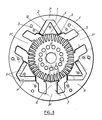
- the improved embodiment illustrated in FIG. 5 is similar to that described above first.
- each permanent pole P has a V-shaped slot in its axis opening towards the air gap B e, the branches of which are formed by two rectangular notches 1, 2 joining at the top of the V and ending, moreover, in the immediate vicinity of the air gap B , reserving only very narrow isthmus 3, 3 of material in the sheet metal T at the ends of the pole shoes 4 bordered by the interpolar notches 5.
- these slots 1, 2 are housed the magnetic plates A which generate the permanent magnetic flux of the motor .
- the cutting of the sheet metal T by punching comprises, in addition to the slots with a polygonal outline 1, 2 intended for housing the permanent magnets A, as described above, polar teeth 6 each provided with a polar expansion 7 and which, after stacking, will constitute the polar nuclei of P '.
- the inductor may comprise, depending on the desired operation, one or more wound poles P '.
- the motor has six poles which are alternately permanent P and wound P '.
- the excitation of the wound poles P ' creates a flux which is generally added to that which is generated by the permanent magnets A, but which can possibly be zero or even subtractive to reduce the total flux in the rotor R.
Landscapes
- Engineering & Computer Science (AREA)
- Power Engineering (AREA)
- Permanent Field Magnets Of Synchronous Machinery (AREA)
- Permanent Magnet Type Synchronous Machine (AREA)
Description
La présente invention concerne une machine électrique à courant continu dont le stator est formé de tôles empilées, avec entrefer cylindrique et excitation permanente obtenue an moyen de plaquettes aimantées qui sont avantageusement, quoique non obligatoirement, à base de terres rares et notamment en samarium-cobalt.The present invention relates to a direct current electric machine whose stator is made of stacked sheets, with cylindrical air gap and permanent excitation obtained by means of magnetic plates which are advantageously, although not necessarily, based on rare earths and in particular in samarium-cobalt. .
Grâce à leurs qualités magnétiques - lesquelles sont très supérieures à celles des aimants classiques - les aimants à base de terres rares permettent aux moteurs à courant continu qui en sont équipés, d'atteindre de très hautes performances. Mais en contrepartie, la mise en oeuvre de tels aimants se heurte à de multiples inconvénients tels que difficultés d'approvisionnement en «tuiles» ou pièces cintrées à la forme exacte du pôle, fragilité de celles-ci, caractère délicat de leur montage et aimantation in situ.Thanks to their magnetic qualities - which are far superior to those of conventional magnets - rare earth magnets allow DC motors fitted with them to achieve very high performance. But in return, the implementation of such magnets comes up against multiple drawbacks such as difficulties in supplying "tiles" or parts bent to the exact shape of the pole, fragility of these, delicate nature of their mounting and magnetization. in situ.
Aussi a-t-on préconisé d'utiliser plutôt des plaquettes rectangulaires juxtaposées qui sont de configuration géométrique simple et d'un coût réduit.It has therefore been recommended to use rather juxtaposed rectangular plates which are of simple geometrical configuration and of reduced cost.
Conformément à la présente invention, on loge ces plaquettes aimantées dans des fentes à contour polygonal fermé pratiquées dans les tôles empilées formant le stator de la machine à courant continu, ledit contour polygonal arrivant à proximité immédiate de l'une au moins des deux extrémités de la région utile du pôle formant l'entrefer et n'y laissant subsister qu'un isthme de tôle très étroit et par conséquent non susceptible de court-circuiter le flux magnétique inducteur utile.In accordance with the present invention, these magnetic plates are housed in slots with a closed polygonal contour formed in the stacked sheets forming the stator of the DC machine, said polygonal contour arriving in the immediate vicinity of at least one of the two ends of the useful region of the pole forming the air gap and leaving only a very narrow sheet isthmus remaining therefrom and therefore not capable of short-circuiting the useful inductive magnetic flux.
Il n'est pas sans intérêt d'observer en passant qu'une aussi faible réserve de matière eût été rédhibitoire dans le cas d'un rotor de machine électrique, en raison des contraintes mécaniques dues à la force centrifuge.It is not without interest to observe in passing that such a low reserve of material would have been unacceptable in the case of an electric machine rotor, due to the mechanical stresses due to centrifugal force.
Il est vrai qu'on a déjà proposé d'intégrer des plaquettes aimantées rectangulaires au stator de machines électriques à courant continu, et l'on pourra se reporter à cet égard aux DE-A-2 947 670 et US-A-4141 137.It is true that it has already been proposed to integrate rectangular magnetic plates with the stator of direct current electric machines, and reference may be made in this respect to DE-A-2,947,670 and US-A-4,141,137 .
Mais le DE-A-2 947 670 ne divulgue pas un tel logement de plaquettes aimantées dans des fentes à contour polygonal fermé laissant subsister un isthme de matière. On se trouve ici en présence d'un circuit magnétique en tôle découpée ou en deux blocs frittés, les aimants étant introduits entre deux demi- stators. Il n'est pas prévu d'encoches fermées pour loger ces aimants.But DE-A-2 947 670 does not disclose such a housing of magnetic plates in slots with closed polygonal outline leaving an isthmus of material. We are here in the presence of a magnetic circuit in cut sheet metal or in two sintered blocks, the magnets being inserted between two half-stators. There are no plans for closed notches to accommodate these magnets.
De son côté, le US-A-4 141 137 utilise des blocs aimantés solidaires qui sont cimentés par une résine époxy contre des faces en regard de la pièce polaire. Ici non plus, on ne trouve pas d'encoches fermées pour le logement de plaquettes aimantées.For its part, US-A-4 141 137 uses integral magnetic blocks which are cemented by an epoxy resin against opposite faces of the pole piece. Here, too, there are no closed notches for housing magnetic plates.
Pour en revenir à la présente invention, des essais effectués avec des moteurs électriques ayant un tel inducteur statorique ont révélé que, si le fait de conserver un flux constant élevé procure un fonctionnement satisfaisant jusqu'à des vitesses de l'ordre de 3000 tr/mn, il n'en est plus de même pour des vitesses supérieures, à cause de l'échauffement exagéré de l'induit dû à l'augmentation importante des pertes fer dans les tôles du rotor, pertes liées à la vitesse et à l'importance du flux. Le rendement décroît alors rapidement et en outre la tension entre les lames du collecteur peut devenir prohibitive à grande vitesse puisque, à flux constant, l'augmentation de vitesse s'obtient par accroissement de la tension d'induit.To return to the present invention, tests carried out with electric motors having such a stator inductor have revealed that, if the fact of maintaining a high constant flux provides satisfactory operation up to speeds of the order of 3000 rpm mn, it is no longer the same for higher speeds, because of the excessive heating of the armature due to the significant increase in iron losses in the rotor sheets, losses related to speed and importance of the flow. The output then decreases rapidly and furthermore the tension between the blades of the collector can become prohibitive at high speed since, at constant flux, the increase in speed is obtained by increasing the armature tension.
Aussi la présente invention a-t-elle également pour objet une variante de réalisation perfectionnée de l'inducteur statorique qui a été défini plus haut et qui:
- - conserve, dans la plage des basses vitesses (par exemple de 0 à environ 3000 tr/mn), les avantages d'un moteur à flux élevé (couple constant et important),
- - permettre d'atteindre des vitesses supérieures (par exemple 6000 tr/mn) sans augmentation prohibitive des pertes fer et de la tension d'alimentation (dans la plage allant de 3000 à 6000 tr/mn, le fonctionnement pourrait être à puissance constante),
- - maintienne un rendement élevé quel que soit le régime.
- - retains, in the low speed range (for example from 0 to around 3000 rpm), the advantages of a high flux motor (constant and high torque),
- - allow higher speeds (for example 6000 rpm) to be reached without prohibitive increase in iron losses and supply voltage (in the range from 3000 to 6000 rpm, operation could be at constant power) ,
- - maintain a high yield whatever the regime.
A cet effet et conformément au perfectionnement évoqué, on remplace un ou plusieurs pôles permanents à plaquettes aimantées logées dans des fentes par un pôle bobiné classique respectif de façon à doter la machine électrique d'un inducteur hybride qui peut avoir avantageusement une succession alternée de pôles à aimants permanents et de pôles bobinés formant une répartition polaire régulière, selon une technique ancienne illustrée notamment par le brevet français BIGNON N 1 407 904 délivré le 28 Juin 1965.To this end and in accordance with the improvement mentioned, one or more permanent poles with magnetic plates housed in slots are replaced by a respective conventional wound pole so as to provide the electric machine with a hybrid inductor which can advantageously have an alternating succession of poles. with permanent magnets and wound poles forming a regular polar distribution, according to an old technique illustrated in particular by the French patent BIGNON N 1 407 904 issued on June 28, 1965.
Cet inducteur hybride permet, grâce à son ou ses pôles bobinés offrant une faculté de variation d'ampères-tours, de réduire le flux dans la plage critique des grandes vitesses, supprimant ainsi - ou du moins réduisant notablement - les inconvénients signalés plus haut, la présence de pôles permanents au côté de pôles bobinés permettant de réduire les pertes dues à l'excitation, celles-ci se limitant à ces dernièrs.This hybrid inductor allows, thanks to its coiled pole (s) offering the possibility of varying ampere-turns, to reduce the flux in the critical range of high speeds, thus eliminating - or at least significantly reducing - the drawbacks mentioned above, the presence of permanent poles alongside coiled poles to reduce losses due to excitation, these being limited to the latter.
La description qui va suivre en regard des dessins annexés, donnée à titre d'exemple non limitatif, fera bien comprendre comment l'invention peut être réalisée.
- La figure 1 est une vue schématique en plan d'un inducteur statorique du moteur quadripolaire, aménagé selon un mode de réalisation de la présente invention.
- Les figures 2, 3 et 4 sont des vues analogues illustrant respectivement trois variantes de réalisation rentrant dans le cadre de la présente invention.
- La figure 5 est une vue schématique en plan d'une tôle découpée de l'empilage statorique conforme à une mode de réalisation préféré de la présente invention, cette tôle étant représentée en position autour du rotor du moteur électrique.
- Figure 1 is a schematic plan view of a stator inductor of the quadrupole motor, arranged according to an embodiment of the present invention.
- Figures 2, 3 and 4 are similar views respectively illustrating three alternative embodiments within the scope of the present invention.
- Figure 5 is a schematic plan view of a cut sheet of the stator stack according to a preferred embodiment of the present invention, this sheet being shown in position around the rotor of the electric motor.
L'inducteur statorique, dans ses diverses variantes représentées sur les figures 1 à 4 et afférentes à un moteur électrique à quatre pôles P, est constitué comme à l'accoutumée d'un empilage de tôles T en métal magnétique découpées en forme générale de couronne dont le bord interne B délimite vers l'extérieur l'entrefer cylindrique, lequel est délimité vers l'intérieur par le rotor (non représenté) de la machine électrique.The stator inductor, in its various variants represented in FIGS. 1 to 4 and relating to an electric motor with four poles P, is made up as usual of a stack of magnetic metal sheets T cut in the general shape of a crown whose internal edge B delimits the cylindrical air gap towards the outside, which is delimited towards the inside by the rotor (not shown) of the electric machine.
Selon la présente invention, on a pratiqué dans ces tôles T des fentes servant de logement à une juxtaposition d'aimants permanents A qui sont formés de plaquettes rectangulaires magnétisées et qui engendrent le flux magnétique inducteur de la machine. Les diverses variantes illustrées se distinguent les unes des autres par la configuration géométrique de ces fentes.According to the present invention, slots T have been made in these sheets serving as housing for a juxtaposition of permanent magnets A which are formed of rectangular magnetized plates and which generate the inductive magnetic flux of the machine. The various variants illustrated differ from each other by the geometric configuration of these slots.
Dans le mode de réalisation de la figure 1, chacun des quatre pôles P du moteur présente dans son axe une fente à configuration en V dont l'angle s'ouvre en direction du bord B de l'entrefer, les branches plus ou moins orthogonales du V étant formées de deux encoches rectangulaires 1, 2 se rejoignant au sommet du V et se terminant par ailleurs à proximité immédiate du bord B de l'entrefer, ne réservant que de très étroits isthmes 3, 3 de matière dans la tôle T. La largeur de chaque encoche 1, 2 est sensiblement égale à celle des plaquettes aimantées A qui y sont logées.In the embodiment of Figure 1, each of the four poles P of the motor has in its axis a V-shaped slot whose angle opens towards the edge B of the air gap, the branches more or less orthogonal of the V being formed of two
Les pôles successifs P sont séparés par des profondes échancrures 5 définissant géométriquement des zones neutres et restreignant le passage des flux de fuites magnétiques interpolaires.The successive poles P are separated by
Un certain nombre de tôles T ainsi découpées sont empilées et maintenues entre elles par tout moyen adéquat de façon à formér un paquet de fer statorique. L'alignement des encoches 1, 2 constitue alors, dans chaque pôle P, deux logements dans lesquels sont introduites des plaquettes d'aimant A de préférence déjà magnétisées, de telle sorte que les faces tournées vers l'entrefer soient de même polarité, pour former un pôle de même nom au niveau de l'épanouissement 4, les pôles consécutifs le long de l'entrefer étant bien entendu de polarité alternée.A number of sheets T thus cut are stacked and held together by any suitable means so as to form a packet of stator iron. The alignment of the
On notera que les étranglements que constituent les isthmes de matière 3 de très faible largeur, obligent le flux magnétique engendré par les plaquettes aimantées A à passer essentiellement par les épanouissements polaires 4 et l'entrefer, c'est-à-dire le parcours utile illustré par les flèches, sans dérivation substantielle de court-circuit dans la matière des tôles T. Un calcul élémentaire de résistance des matériaux établit qu'une aussi faible réserve de matière en 3 n'est possible que dans l'immobilité statorique, en l'absence de toute force centrifuge.It will be noted that the constrictions that constitute the isthmus of
On notera également que l'étendue linéaire totale des enchoches 1, 2 remplies de plaquettes aimantées A, est nettement plus grande que l'étendue de l'épanouissement polaire 4 bordant l'entrefer, d'où une surface active d'aimants bien supérieure à ta surface utile d'entrefer et par conséquent un effet notable de concentration de flux magnétique permettant d'obtenir une induction plus élevée dans l'entrefer. Cet effet concentrateur de flux est d'ailleurs d'autant plus prononcé que les parcours depuis les encoches magnétiques 1, 2 jusqu'à l'épanouissement polaire 4 se font selon des rayons décroissants en raison de la situation externe (par rapport à l'entrefer) du stator, ce qui n'est évidement pas le cas du rotor (non représenté) qui, étant interne (toujours par rapport à l'entrefer), verrait les parcours en question se faire au contraire selon des rayons croissants.It will also be noted that the total linear extent of the
Il n'est d'ailleurs nullement impératif de combler tous les logements 1-2 par des plaquettes aimantées A et l'on pourrait fort bien, si l'on voulait réduire sensiblement le prix de revient de la machine, ne remplir de plaquettes aimantées que les logements d'un pôle sur deux et se contenter d'un remplissage de fer pour le pôle suivant.It is moreover in no way imperative to fill all the housings 1-2 with magnetic plates A and we could very well, if we wanted to significantly reduce the cost price of the machine, do not fill with magnetic plates than the housings of one pole out of two and be satisfied with an iron filling for the next pole.
A l'invesre, on peut accroître la longueur efficace des fentes en les constituant de plus de deux encoches telles que 1, 2 de la figure 1.On the other hand, the effective length of the slits can be increased by constituting them with more than two notches such as 1, 2 in FIG. 1.
Ainsi, les figures 2 et 3 montrent respectivement des variantes à trois et quatre encoches consécutives à contour polygonal en U s'ouvrant toujours en direction du bord d'entrefer B et ne laissant subsister en bout que des isthmes 3, 3 très étroits.Thus, FIGS. 2 and 3 respectively show variants with three and four consecutive notches with a U-shaped polygonal outline always opening towards the gap edge B and leaving only very narrow isthmus 3, 3 remaining at the end.
La figure 4 montre une variante économique permettant le réalisation de moteurs de faible encombrement, avec une seule plaquette A par pôle P, plus épaisse que les plaquettes minces précédentes mais néanmoins moins chère que deux plaquettes minces. Dans ce cas, la culasse éventuelle C doit être en matériau amagnétique.FIG. 4 shows an economical variant allowing the production of compact motors, with a single plate A per pole P, thicker than the preceding thin plates but nevertheless less expensive than two thin plates. In this case, the possible cylinder head C must be made of non-magnetic material.
Le mode de réalisation perfectionné illustré par la figure 5 se rapproche de celui décrit plus haut en premier.The improved embodiment illustrated in FIG. 5 is similar to that described above first.
On y retrouve ainsi les pôles permanents P (ici au nombre de trois et à 120°C les uns des autres) obtenus par empilage des tôles poinçonnées identiques T délimitant avec le rotor R l'entrefer cylindrique B. Comme précédemment, chaque pôle permanent P présente dans son axe une fente à configuration en V s'ouvrant vers l'entrefer B e dont les branches sont formées de deux encoches rectangulaires 1, 2 se rejoignant au sommet du V et se terminant par ailleurs à proximité immédiate de l'entrefer B, ne réservant que de très étroits isthmes 3, 3 de matière dans la tôle T aux extrémités des épanouissements polaires 4 bordés par les échancrures interpolaires 5. Dans ces fentes 1, 2 sont logées les plaquettes aimantées A qui engendrent le flux magnétique permanent du moteur.There are thus the permanent poles P (here three in number and at 120 ° C from each other) obtained by stacking identical punched sheets T delimiting with the rotor R the cylindrical air gap B. As before, each permanent pole P has a V-shaped slot in its axis opening towards the air gap B e, the branches of which are formed by two
Entre les pôles permanents P à plaquettes aimantées A et conformément au perfectionnement visé sont intercalés des potes bobinés P'.Between the permanent poles P with magnetic plates A and in accordance with the improvement sought are interposed with wounded mates P '.
A cet effet, la découpe de la tôlerie T par poinçonnage comporte, outre les fentes à contour polygonal 1, 2 destinées au logement des aimants permanents A, telles que décrites précédemment, des dents po- laires 6 munies chacune d'un épanouissement polaire 7 et qui, après empilage, constitueront les noyaux polaires de P'.To this end, the cutting of the sheet metal T by punching comprises, in addition to the slots with a
L'inducteur peut comporter, selon le fontionne- ment désiré, un seul ou plusieurs pôles bobinés P'. Dans l'exemple illustré sur la figure 5. le moteur comporte six pôles qui sont alternativement permanents P et bobinés P'.The inductor may comprise, depending on the desired operation, one or more wound poles P '. In the example illustrated in Figure 5. the motor has six poles which are alternately permanent P and wound P '.
L'excitation des pôles bobinés P' crée un flux qui s'ajoute généralement à celui qui est engendré par les aimants permanents A, mais qui peut éventuellement être nul ou même soustractif pour réduire le flux total dans le rotor R.The excitation of the wound poles P 'creates a flux which is generally added to that which is generated by the permanent magnets A, but which can possibly be zero or even subtractive to reduce the total flux in the rotor R.
Plus précisément, on pilotera l'excitation des pôles bobinés P' selon le régime de rotation du moteur qu'on peut subdiviser en trois plages:
- 1 °) Pour les basses vitesses (par exemple de 0 à 3000 tr/mn), on opère à couple constant, les ampères-tours des pôles bobinés P' - qui sont additifs vis-à-vis du flux produit par les pôles permanents P - étant au maximum afin d'avoir un courant d'induit minimum. La vitesse du moteur varie alors comme la tension appliquée au collecteur.
- 2°) Pour les vitesses plus élevées (par exemple de 3000 à 5000 tr/mn) que l'on ne peut atteindre en continuant à augmenter la tension d'alimentation sous peine d'étincelles au collecteur et de chute de rendement, on opère à puissance constante en réduisant progressivement le flux par réduction des ampères-tours des pôles bobinés P' depuis leur maximum [par exemple à 3000 tr/mn comme indiqué plus haut sous 10)] jusqu'à 0 (par exemple à 5000 tr/mn).
- 3°) Pour les très grandes vitesses (par exemple de 5000 à 6000 tr/mn), on opère toujours à puissance constante, mais en inversant alors les ampères-tours des pôles bobinés P' pour venir en soustraction du flux engendré par les pôles permanents P. On ne peut évidemment poursuivre trop loin cette inversion des ampères-tours des pôles bobinés P' car on risquerait de démagnétiser les pôles permanents P.
- 1 °) For low speeds (for example from 0 to 3000 rpm), the ampere-turns of the wound poles P '- which are additive, are operated at constant torque with respect to the flux produced by the permanent poles P - being at the maximum in order to have a minimum armature current. The motor speed then varies as the voltage applied to the collector.
- 2 °) For higher speeds (for example from 3000 to 5000 rpm) which cannot be reached by continuing to increase the supply voltage under penalty of sparks at the collector and drop in efficiency, the operation is carried out at constant power by gradually reducing the flux by reducing the ampere-turns of the wound poles P 'from their maximum (for example at 3000 rpm as indicated above under 10)] to 0 (for example at 5000 rpm ).
- 3 °) For very high speeds (for example from 5000 to 6000 rpm), one always operates at constant power, but then reversing the ampere-turns of the wound poles P 'to subtract the flux generated by the poles permanent P. Obviously, this inversion of the ampere-turns of the wound poles P 'cannot be pursued too far because there is a risk of demagnetizing the permanent poles P.
Le pilotage des ampères-tours des pôles bobinés P' qui vient d'être décrit (maintien à leur valeur additive maximum dans un premier régime de basses vitesses, décroissance jusqu'a l'annulation dans un second régime de vitesses intermédiaires et inversion de sens pour les rendre soustractifs dans un troisième régime de grandes vitesses) est aisément assuré par un montage classique de commande du courant d'excitation, à partir d'une dynamo tachymétrique fournissant un signal de vitesse à un détecteur de seuil réglé sur la vitesse de transition désirée (3000 tr/mn dans l'exemple considéré).The control of the ampere-turns of the wound poles P 'which has just been described (maintenance at their maximum additive value in a first regime of low speeds, decay until cancellation in a second regime of intermediate speeds and reversal of direction to make them subtractive in a third high speed regime) is easily ensured by a conventional circuit for controlling the excitation current, from a tachometric dynamo supplying a speed signal to a threshold detector set to the transition speed desired (3000 rpm in the example considered).
Le moteur à inducteur hybride P-P' qui vient d'être décrit en regard de la figure 5 présente des avantages appréciables:
- - Optimisation du fonctionnement dans une plage élargie de vitesse;
- - Facilité de régulation du flux par pilotage du courant d'excitation en fonction de la vitesse désirée;
- - Pas de risque d'emballement du moteur si par accident le courant d'excitation des pôles bobinés P' vient à s'annuler;
- - Rendement amélioré par rapport aux solutions traditionnelles, une partie seulement des pôles étant bobinée (réduction des pertes d'excitation).
- - Optimization of operation in an extended speed range;
- - Easy flow regulation by controlling the excitation current as a function of the desired speed;
- - No risk of motor runaway if by accident the excitation current of the wound poles P 'is canceled;
- - Improved efficiency compared to traditional solutions, only part of the poles being wound (reduction of excitation losses).
Il va de soi que les modes de réalisation décrits ne sont que des exemples et qu'on pourrait les modifier, notamment par substitution d'équivalents techniques, sans sortir pour cela du cadre de l'invention.It goes without saying that the embodiments described are only examples and that they could be modified, in particular by substitution of technical equivalents, without departing from the scope of the invention.
Claims (6)
Applications Claiming Priority (4)
| Application Number | Priority Date | Filing Date | Title |
|---|---|---|---|
| FR8115289 | 1981-08-06 | ||
| FR8115289A FR2511209B1 (en) | 1981-08-06 | 1981-08-06 | DIRECT CURRENT, CYLINDRICAL GAP AND PERMANENTLY DRIVEN MACHINE |
| FR8202061A FR2521363B2 (en) | 1982-02-09 | 1982-02-09 | DIRECT CURRENT, CYLINDRICAL GAP AND PERMANENTLY DRIVEN MACHINE |
| FR8202061 | 1982-02-09 |
Publications (2)
| Publication Number | Publication Date |
|---|---|
| EP0072297A1 EP0072297A1 (en) | 1983-02-16 |
| EP0072297B1 true EP0072297B1 (en) | 1985-05-22 |
Family
ID=26222501
Family Applications (1)
| Application Number | Title | Priority Date | Filing Date |
|---|---|---|---|
| EP19820401414 Expired EP0072297B1 (en) | 1981-08-06 | 1982-07-29 | Direct current electrical machine with cylindrical air gap and permanent excitation |
Country Status (3)
| Country | Link |
|---|---|
| EP (1) | EP0072297B1 (en) |
| DE (1) | DE3263750D1 (en) |
| ES (1) | ES514772A0 (en) |
Cited By (1)
| Publication number | Priority date | Publication date | Assignee | Title |
|---|---|---|---|---|
| US11942424B2 (en) | 2021-12-01 | 2024-03-26 | International Business Machines Corporation | Via patterning for integrated circuits |
Families Citing this family (4)
| Publication number | Priority date | Publication date | Assignee | Title |
|---|---|---|---|---|
| FR2559321B1 (en) * | 1984-02-06 | 1986-11-21 | Applic Mach Motrices | LOW-VOLTAGE ELECTRIC DRIVE DEVICE FOR A HIGH-INERTIA ROTATING MASS AND MOTOR BEING PART OF THIS DEVICE |
| GB2209878A (en) * | 1987-09-11 | 1989-05-24 | Johnson Electric Ind Mfg | Laminated stator for D.C. permanent magnet electric motor |
| FR2639159B1 (en) * | 1988-11-14 | 1995-04-21 | Equip Electr Moteur | STATOR OF ROTATING ELECTRIC MACHINE WITH PERMANENT MAGNET INDUCERS |
| US5920139A (en) * | 1996-03-31 | 1999-07-06 | Sanyo Electric Co. Ltd. | Magnet motor stator |
Family Cites Families (6)
| Publication number | Priority date | Publication date | Assignee | Title |
|---|---|---|---|---|
| FR1407904A (en) * | 1964-07-17 | 1965-08-06 | Electric motor with permanent magnets with several rotation speeds | |
| US3840763A (en) * | 1973-07-09 | 1974-10-08 | Gen Electric | Low flux density permanent magnet field configuration |
| US4088177A (en) * | 1976-01-07 | 1978-05-09 | General Electric Company | Permanent magnet D.C. dynamoelectric machine and method of making same |
| FR2386179A1 (en) * | 1977-03-28 | 1978-10-27 | Kollmorgen Tech Corp | PERFECTED ELECTRIC ROTATING MACHINES |
| US4141137A (en) * | 1977-10-25 | 1979-02-27 | General Electric Company | Method of making a permanent magnet field pole for a direct current dynamoelectric machine |
| DE2947670A1 (en) * | 1979-11-27 | 1981-07-23 | SWF-Spezialfabrik für Autozubehör Gustav Rau GmbH, 7120 Bietigheim-Bissingen | Electromotor using relatively weak permanent magnets - having poles faces inclined w.r.t. magnetic yoke and large compared with its effective cross=section |
-
1982
- 1982-07-29 EP EP19820401414 patent/EP0072297B1/en not_active Expired
- 1982-07-29 DE DE8282401414T patent/DE3263750D1/en not_active Expired
- 1982-08-05 ES ES514772A patent/ES514772A0/en active Granted
Cited By (1)
| Publication number | Priority date | Publication date | Assignee | Title |
|---|---|---|---|---|
| US11942424B2 (en) | 2021-12-01 | 2024-03-26 | International Business Machines Corporation | Via patterning for integrated circuits |
Also Published As
| Publication number | Publication date |
|---|---|
| ES8305982A1 (en) | 1983-05-01 |
| ES514772A0 (en) | 1983-05-01 |
| EP0072297A1 (en) | 1983-02-16 |
| DE3263750D1 (en) | 1985-06-27 |
Similar Documents
| Publication | Publication Date | Title |
|---|---|---|
| EP0909010B1 (en) | Electrical machine with flux commutation, particularly alternator for vehicle | |
| CA2482125C (en) | Transverse flow electric machine with a toothed rotor | |
| EP2209193B1 (en) | Rotating electric machine with saliant poles | |
| EP2917999B1 (en) | Synchronous electric motor with permanent magnets and electric compressor comprising such an electric motor | |
| FR2537799A1 (en) | ||
| EP3210285A1 (en) | Polyphase motor having an alternation of permanent magnets and salient poles | |
| FR2511209A1 (en) | ELECTRIC MACHINE WITH CONTINUOUS CURRENT, CYLINDRICAL GASKET AND PERMANENT EXCITATION | |
| EP2209192A1 (en) | Rotating electric machine, in particular for the starter of an automotive vehicle | |
| EP0072297B1 (en) | Direct current electrical machine with cylindrical air gap and permanent excitation | |
| EP3158630B1 (en) | Direct drive and double air gap linear electromagnetic motor with reduction of the detent force in the electromagnetic motor | |
| EP2878071B1 (en) | Winding for a stator element of a permanent-magnet motor or generator, comprising at least one single-component, rigid limb, and method for producing same | |
| EP3387742B1 (en) | Rotor of an axial-flow electromagnetic motor having a corrugated-shape integral magnet | |
| WO2015049467A2 (en) | Multiphase electric rotating machine with at least five phases | |
| FR2945683A1 (en) | VERNIER MACHINE WITH INSIDE MAGNETS. | |
| FR2618616A1 (en) | Electric machine with high drive and/or positioning torque | |
| EP0660494A1 (en) | Synchronous permanent magnet electric machine with the possibility to change the magnetic flux in the gap | |
| EP2372874B1 (en) | Synchronous rotating electric machine with permanent magnets and flux concentration | |
| WO2014122374A1 (en) | Electromagnetic motor or generator with a plurality of air gaps having permanent magnets and ironless winding element | |
| EP0042884A1 (en) | Electromagnetically excited magnet motor | |
| CH622914A5 (en) | Electric motor | |
| FR2775393A1 (en) | Hybrid vernier(RTM) effect variable reluctance dynamo electric motor having a large range and speed. | |
| FR3086118A1 (en) | ROTATING ELECTRIC MACHINE WITH REDUCED MASS ROTOR | |
| FR2809240A1 (en) | Homo-polar electrical machine and fabrication method, uses stampings from a flat metallic sheet, shaped teeth to support conductors | |
| EP0680130A1 (en) | Synchronous electric machine with smooth poles and constant air gap | |
| FR2521363A2 (en) | DC electrical machine with samarium-cobalt magnet - has cylindrical air gap and permanent excitation by magnetised plates in polygonal slots among laminations |
Legal Events
| Date | Code | Title | Description |
|---|---|---|---|
| PUAI | Public reference made under article 153(3) epc to a published international application that has entered the european phase |
Free format text: ORIGINAL CODE: 0009012 |
|
| AK | Designated contracting states |
Designated state(s): BE DE FR IT SE |
|
| 17P | Request for examination filed |
Effective date: 19830121 |
|
| ITF | It: translation for a ep patent filed | ||
| GRAA | (expected) grant |
Free format text: ORIGINAL CODE: 0009210 |
|
| AK | Designated contracting states |
Designated state(s): BE DE FR IT SE |
|
| REF | Corresponds to: |
Ref document number: 3263750 Country of ref document: DE Date of ref document: 19850627 |
|
| PLBE | No opposition filed within time limit |
Free format text: ORIGINAL CODE: 0009261 |
|
| STAA | Information on the status of an ep patent application or granted ep patent |
Free format text: STATUS: NO OPPOSITION FILED WITHIN TIME LIMIT |
|
| 26N | No opposition filed | ||
| ITTA | It: last paid annual fee | ||
| EAL | Se: european patent in force in sweden |
Ref document number: 82401414.6 |
|
| REG | Reference to a national code |
Ref country code: FR Ref legal event code: TP |
|
| REG | Reference to a national code |
Ref country code: FR Ref legal event code: TP Ref country code: FR Ref legal event code: CD Ref country code: FR Ref legal event code: CA |
|
| BECA | Be: change of holder's address |
Free format text: 980507 S.A. *PARVEX:8 AVENUE DU LAC, BP 245, F-21007 DIJON |
|
| BECH | Be: change of holder |
Free format text: 980507 S.A. *PARVEX:8 AVENUE DU LAC, BP 245, F-21007 DIJON |
|
| BECN | Be: change of holder's name |
Effective date: 19980507 |
|
| PGFP | Annual fee paid to national office [announced via postgrant information from national office to epo] |
Ref country code: BE Payment date: 20000609 Year of fee payment: 19 |
|
| PGFP | Annual fee paid to national office [announced via postgrant information from national office to epo] |
Ref country code: SE Payment date: 20000614 Year of fee payment: 19 |
|
| PGFP | Annual fee paid to national office [announced via postgrant information from national office to epo] |
Ref country code: FR Payment date: 20000619 Year of fee payment: 19 |
|
| PGFP | Annual fee paid to national office [announced via postgrant information from national office to epo] |
Ref country code: DE Payment date: 20000912 Year of fee payment: 19 |
|
| PG25 | Lapsed in a contracting state [announced via postgrant information from national office to epo] |
Ref country code: SE Free format text: LAPSE BECAUSE OF NON-PAYMENT OF DUE FEES Effective date: 20010730 |
|
| PG25 | Lapsed in a contracting state [announced via postgrant information from national office to epo] |
Ref country code: BE Free format text: LAPSE BECAUSE OF NON-PAYMENT OF DUE FEES Effective date: 20010731 |
|
| BERE | Be: lapsed |
Owner name: S.A. PARVEX Effective date: 20010731 |
|
| EUG | Se: european patent has lapsed |
Ref document number: 82401414.6 |
|
| PG25 | Lapsed in a contracting state [announced via postgrant information from national office to epo] |
Ref country code: FR Free format text: LAPSE BECAUSE OF NON-PAYMENT OF DUE FEES Effective date: 20020329 |
|
| PG25 | Lapsed in a contracting state [announced via postgrant information from national office to epo] |
Ref country code: DE Free format text: LAPSE BECAUSE OF NON-PAYMENT OF DUE FEES Effective date: 20020501 |
|
| REG | Reference to a national code |
Ref country code: FR Ref legal event code: ST |