EP0072297B1 - Gleichstrommaschine mit zylindrischem Luftspalt und Dauermagneterregung - Google Patents
Gleichstrommaschine mit zylindrischem Luftspalt und Dauermagneterregung Download PDFInfo
- Publication number
- EP0072297B1 EP0072297B1 EP19820401414 EP82401414A EP0072297B1 EP 0072297 B1 EP0072297 B1 EP 0072297B1 EP 19820401414 EP19820401414 EP 19820401414 EP 82401414 A EP82401414 A EP 82401414A EP 0072297 B1 EP0072297 B1 EP 0072297B1
- Authority
- EP
- European Patent Office
- Prior art keywords
- electrical machine
- slots
- poles
- air gap
- machine according
- Prior art date
- Legal status (The legal status is an assumption and is not a legal conclusion. Google has not performed a legal analysis and makes no representation as to the accuracy of the status listed.)
- Expired
Links
Images

Classifications
-
- H—ELECTRICITY
- H02—GENERATION; CONVERSION OR DISTRIBUTION OF ELECTRIC POWER
- H02K—DYNAMO-ELECTRIC MACHINES
- H02K23/00—DC commutator motors or generators having mechanical commutator; Universal AC/DC commutator motors
- H02K23/02—DC commutator motors or generators having mechanical commutator; Universal AC/DC commutator motors characterised by arrangement for exciting
- H02K23/04—DC commutator motors or generators having mechanical commutator; Universal AC/DC commutator motors characterised by arrangement for exciting having permanent magnet excitation
Definitions
- the present invention relates to a direct current electric machine whose stator is made of stacked sheets, with cylindrical air gap and permanent excitation obtained by means of magnetic plates which are advantageously, although not necessarily, based on rare earths and in particular in samarium-cobalt. .
- these magnetic plates are housed in slots with a closed polygonal contour formed in the stacked sheets forming the stator of the DC machine, said polygonal contour arriving in the immediate vicinity of at least one of the two ends of the useful region of the pole forming the air gap and leaving only a very narrow sheet isthmus remaining therefrom and therefore not capable of short-circuiting the useful inductive magnetic flux.
- DE-A-2 947 670 does not disclose such a housing of magnetic plates in slots with closed polygonal outline leaving an isthmus of material.
- US-A-4 141 137 uses integral magnetic blocks which are cemented by an epoxy resin against opposite faces of the pole piece. Here, too, there are no closed notches for housing magnetic plates.
- one or more permanent poles with magnetic plates housed in slots are replaced by a respective conventional wound pole so as to provide the electric machine with a hybrid inductor which can advantageously have an alternating succession of poles.
- permanent magnets and wound poles forming a regular polar distribution, according to an old technique illustrated in particular by the French patent BIGNON N 1 407 904 issued on June 28, 1965.
- This hybrid inductor allows, thanks to its coiled pole (s) offering the possibility of varying ampere-turns, to reduce the flux in the critical range of high speeds, thus eliminating - or at least significantly reducing - the drawbacks mentioned above, the presence of permanent poles alongside coiled poles to reduce losses due to excitation, these being limited to the latter.
- the stator inductor in its various variants represented in FIGS. 1 to 4 and relating to an electric motor with four poles P, is made up as usual of a stack of magnetic metal sheets T cut in the general shape of a crown whose internal edge B delimits the cylindrical air gap towards the outside, which is delimited towards the inside by the rotor (not shown) of the electric machine.
- slots T have been made in these sheets serving as housing for a juxtaposition of permanent magnets A which are formed of rectangular magnetized plates and which generate the inductive magnetic flux of the machine.
- the various variants illustrated differ from each other by the geometric configuration of these slots.
- each of the four poles P of the motor has in its axis a V-shaped slot whose angle opens towards the edge B of the air gap, the branches more or less orthogonal of the V being formed of two rectangular notches 1, 2 joining at the top of the V and ending, moreover, in the immediate vicinity of the edge B of the air gap, reserving only very narrow isthmus 3, 3 of material in the sheet metal T.
- the width of each notch 1, 2 is substantially equal to that of the magnetic plates A which are housed there.
- the successive poles P are separated by deep indentations 5 geometrically defining neutral zones and restricting the passage of the fluxes of interpolar magnetic leaks.
- a number of sheets T thus cut are stacked and held together by any suitable means so as to form a packet of stator iron.
- the alignment of the notches 1, 2 then constitutes, in each pole P, two housings into which are inserted magnet plates A, preferably already magnetized, so that the faces facing the air gap are of the same polarity, for form a pole of the same name at the level of the opening 4, the consecutive poles along the air gap being of course of alternating polarity.
- the total linear extent of the notches 1, 2 filled with magnetic plates A is significantly greater than the extent of the pole breakout 4 bordering the air gap, hence a much greater active surface of magnets to your useful airgap surface and consequently a notable effect of magnetic flux concentration allowing to obtain a higher induction in the airgap.
- This flux concentrating effect is moreover all the more pronounced as the paths from the magnetic notches 1, 2 to the polar blooming 4 are made according to decreasing radii due to the external situation (relative to the air gap) of the stator, which is obviously not the case of the rotor (not shown) which, being internal (always relative to the air gap), would see the paths in question on the contrary according to increasing radii.
- the effective length of the slits can be increased by constituting them with more than two notches such as 1, 2 in FIG. 1.
- FIGS. 2 and 3 respectively show variants with three and four consecutive notches with a U-shaped polygonal outline always opening towards the gap edge B and leaving only very narrow isthmus 3, 3 remaining at the end.
- FIG. 4 shows an economical variant allowing the production of compact motors, with a single plate A per pole P, thicker than the preceding thin plates but nevertheless less expensive than two thin plates.
- the possible cylinder head C must be made of non-magnetic material.
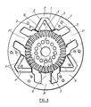
- the improved embodiment illustrated in FIG. 5 is similar to that described above first.
- each permanent pole P has a V-shaped slot in its axis opening towards the air gap B e, the branches of which are formed by two rectangular notches 1, 2 joining at the top of the V and ending, moreover, in the immediate vicinity of the air gap B , reserving only very narrow isthmus 3, 3 of material in the sheet metal T at the ends of the pole shoes 4 bordered by the interpolar notches 5.
- these slots 1, 2 are housed the magnetic plates A which generate the permanent magnetic flux of the motor .
- the cutting of the sheet metal T by punching comprises, in addition to the slots with a polygonal outline 1, 2 intended for housing the permanent magnets A, as described above, polar teeth 6 each provided with a polar expansion 7 and which, after stacking, will constitute the polar nuclei of P '.
- the inductor may comprise, depending on the desired operation, one or more wound poles P '.
- the motor has six poles which are alternately permanent P and wound P '.
- the excitation of the wound poles P ' creates a flux which is generally added to that which is generated by the permanent magnets A, but which can possibly be zero or even subtractive to reduce the total flux in the rotor R.
Landscapes
- Engineering & Computer Science (AREA)
- Power Engineering (AREA)
- Permanent Field Magnets Of Synchronous Machinery (AREA)
- Permanent Magnet Type Synchronous Machine (AREA)
Claims (6)
Applications Claiming Priority (4)
| Application Number | Priority Date | Filing Date | Title |
|---|---|---|---|
| FR8115289 | 1981-08-06 | ||
| FR8115289A FR2511209B1 (fr) | 1981-08-06 | 1981-08-06 | Machine electrique a courant continu, a entrefer cylindrique et a excitation permanente |
| FR8202061 | 1982-02-09 | ||
| FR8202061A FR2521363B2 (fr) | 1982-02-09 | 1982-02-09 | Machine electrique a courant continu, a entrefer cylindrique et a excitation permanente |
Publications (2)
| Publication Number | Publication Date |
|---|---|
| EP0072297A1 EP0072297A1 (de) | 1983-02-16 |
| EP0072297B1 true EP0072297B1 (de) | 1985-05-22 |
Family
ID=26222501
Family Applications (1)
| Application Number | Title | Priority Date | Filing Date |
|---|---|---|---|
| EP19820401414 Expired EP0072297B1 (de) | 1981-08-06 | 1982-07-29 | Gleichstrommaschine mit zylindrischem Luftspalt und Dauermagneterregung |
Country Status (3)
| Country | Link |
|---|---|
| EP (1) | EP0072297B1 (de) |
| DE (1) | DE3263750D1 (de) |
| ES (1) | ES8305982A1 (de) |
Cited By (1)
| Publication number | Priority date | Publication date | Assignee | Title |
|---|---|---|---|---|
| US11942424B2 (en) | 2021-12-01 | 2024-03-26 | International Business Machines Corporation | Via patterning for integrated circuits |
Families Citing this family (4)
| Publication number | Priority date | Publication date | Assignee | Title |
|---|---|---|---|---|
| FR2559321B1 (fr) * | 1984-02-06 | 1986-11-21 | Applic Mach Motrices | Dispositif d'entrainement electrique en basse tension d'une masse tournante de forte inertie et moteur faisant partie de ce dispositif |
| GB2209878A (en) * | 1987-09-11 | 1989-05-24 | Johnson Electric Ind Mfg | Laminated stator for D.C. permanent magnet electric motor |
| FR2639159B1 (fr) * | 1988-11-14 | 1995-04-21 | Equip Electr Moteur | Stator de machine electrique tournante a poles inducteurs a aimant permanent |
| US5920139A (en) * | 1996-03-31 | 1999-07-06 | Sanyo Electric Co. Ltd. | Magnet motor stator |
Family Cites Families (6)
| Publication number | Priority date | Publication date | Assignee | Title |
|---|---|---|---|---|
| FR1407904A (fr) * | 1964-07-17 | 1965-08-06 | Moteur électrique avec aimants permanents à plusieurs vitesses de rotation | |
| US3840763A (en) * | 1973-07-09 | 1974-10-08 | Gen Electric | Low flux density permanent magnet field configuration |
| US4088177A (en) * | 1976-01-07 | 1978-05-09 | General Electric Company | Permanent magnet D.C. dynamoelectric machine and method of making same |
| FR2386179A1 (fr) * | 1977-03-28 | 1978-10-27 | Kollmorgen Tech Corp | Machines electriques tournantes perfectionnees |
| US4141137A (en) * | 1977-10-25 | 1979-02-27 | General Electric Company | Method of making a permanent magnet field pole for a direct current dynamoelectric machine |
| DE2947670A1 (de) * | 1979-11-27 | 1981-07-23 | SWF-Spezialfabrik für Autozubehör Gustav Rau GmbH, 7120 Bietigheim-Bissingen | Elektromotor |
-
1982
- 1982-07-29 DE DE8282401414T patent/DE3263750D1/de not_active Expired
- 1982-07-29 EP EP19820401414 patent/EP0072297B1/de not_active Expired
- 1982-08-05 ES ES514772A patent/ES8305982A1/es not_active Expired
Cited By (1)
| Publication number | Priority date | Publication date | Assignee | Title |
|---|---|---|---|---|
| US11942424B2 (en) | 2021-12-01 | 2024-03-26 | International Business Machines Corporation | Via patterning for integrated circuits |
Also Published As
| Publication number | Publication date |
|---|---|
| DE3263750D1 (en) | 1985-06-27 |
| ES514772A0 (es) | 1983-05-01 |
| ES8305982A1 (es) | 1983-05-01 |
| EP0072297A1 (de) | 1983-02-16 |
Similar Documents
| Publication | Publication Date | Title |
|---|---|---|
| EP0909010B1 (de) | Elektrische Maschine mit Flussumschaltung, insbesondere Stromgenerator für Kraftfahrzeuge | |
| CA2482125C (fr) | Machine electrique a flux transverse a rotor dente | |
| EP2209193B1 (de) | Elektrische Drehendemaschine mit Schenkelpolen | |
| FR2511209A1 (fr) | Machine electrique a courant continu, a entrefer cylindrique et a excitation permanente | |
| EP3210285A1 (de) | Mehrphasenmotor mit abwechselnder anordnung aus dauermagneten und schenkelpolen | |
| EP2917999A1 (de) | Synchronmotor mit dauermagneten und elektrischer kompressor mit solch einem elektromotor | |
| EP2209192A1 (de) | Drehende elektrische Maschine, insbesondere für Kraftfahrzeuganlasser | |
| EP0072297B1 (de) | Gleichstrommaschine mit zylindrischem Luftspalt und Dauermagneterregung | |
| EP3158630B1 (de) | Direktantrieb und linearer, elektromagnetischer doppelluftspaltmotor mit verminderung der rastkraft im elektromagnetischen motor | |
| EP3387742B1 (de) | Rotor für einen elektromagnetischen axialflussmotor mit welligem integriertem magnet | |
| EP2878071B1 (de) | Wicklung für ein statorelement eines permanentmagnetmotors oder generators mit mindestens einem einkomponentigen starren glied und herstellungsverfahren dafür | |
| FR2945683A1 (fr) | Machine vernier a aimants insires. | |
| FR2618616A1 (fr) | Machine electrique a couple d'entrainement et/ou de positionnement eleve | |
| EP0660494A1 (de) | Dauermagnetsynchronmaschine die eine Änderung des magnetischen Flusses in dem Spalt ermöglicht | |
| WO2015049467A2 (fr) | Machine electrique tournante polyphasee a au moins cinq phases | |
| WO2014122374A1 (fr) | Moteur ou génératrice électromagnétique polyentrefers à aimants permanents et élément à bobinage sans fer | |
| EP0042884A1 (de) | Magnetmotor mit elektromagnetischer Erregung | |
| CH622914A5 (en) | Electric motor | |
| FR2775393A1 (fr) | Machine dynamo-electrique a reluctance variable hybride a effet vernier a grande plage et vitesse | |
| FR3086118A1 (fr) | Machine electrique tournante munie d'un rotor a masse reduite | |
| FR2809240A1 (fr) | Machine electrique homopolaire et procede de fabrication d'une telle machine | |
| EP0680130A1 (de) | Elektrische Synchronmaschine mit glatten Polen und konstantem Luftspalt | |
| FR3084793A1 (fr) | Machine electrique tournante munie d'un bobinage a configuration optimisee | |
| FR2521363A2 (fr) | Machine electrique a courant continu, a entrefer cylindrique et a excitation permanente | |
| FR3133280A1 (fr) | Moteur électromagnétique à concentration de flux magnétique |
Legal Events
| Date | Code | Title | Description |
|---|---|---|---|
| PUAI | Public reference made under article 153(3) epc to a published international application that has entered the european phase |
Free format text: ORIGINAL CODE: 0009012 |
|
| AK | Designated contracting states |
Designated state(s): BE DE FR IT SE |
|
| 17P | Request for examination filed |
Effective date: 19830121 |
|
| ITF | It: translation for a ep patent filed |
Owner name: JACOBACCI & PERANI S.P.A. |
|
| GRAA | (expected) grant |
Free format text: ORIGINAL CODE: 0009210 |
|
| AK | Designated contracting states |
Designated state(s): BE DE FR IT SE |
|
| REF | Corresponds to: |
Ref document number: 3263750 Country of ref document: DE Date of ref document: 19850627 |
|
| PLBE | No opposition filed within time limit |
Free format text: ORIGINAL CODE: 0009261 |
|
| STAA | Information on the status of an ep patent application or granted ep patent |
Free format text: STATUS: NO OPPOSITION FILED WITHIN TIME LIMIT |
|
| 26N | No opposition filed | ||
| ITTA | It: last paid annual fee | ||
| EAL | Se: european patent in force in sweden |
Ref document number: 82401414.6 |
|
| REG | Reference to a national code |
Ref country code: FR Ref legal event code: TP |
|
| REG | Reference to a national code |
Ref country code: FR Ref legal event code: TP Ref country code: FR Ref legal event code: CD Ref country code: FR Ref legal event code: CA |
|
| BECA | Be: change of holder's address |
Free format text: 980507 S.A. *PARVEX:8 AVENUE DU LAC, BP 245, F-21007 DIJON |
|
| BECH | Be: change of holder |
Free format text: 980507 S.A. *PARVEX:8 AVENUE DU LAC, BP 245, F-21007 DIJON |
|
| BECN | Be: change of holder's name |
Effective date: 19980507 |
|
| PGFP | Annual fee paid to national office [announced via postgrant information from national office to epo] |
Ref country code: BE Payment date: 20000609 Year of fee payment: 19 |
|
| PGFP | Annual fee paid to national office [announced via postgrant information from national office to epo] |
Ref country code: SE Payment date: 20000614 Year of fee payment: 19 |
|
| PGFP | Annual fee paid to national office [announced via postgrant information from national office to epo] |
Ref country code: FR Payment date: 20000619 Year of fee payment: 19 |
|
| PGFP | Annual fee paid to national office [announced via postgrant information from national office to epo] |
Ref country code: DE Payment date: 20000912 Year of fee payment: 19 |
|
| PG25 | Lapsed in a contracting state [announced via postgrant information from national office to epo] |
Ref country code: SE Free format text: LAPSE BECAUSE OF NON-PAYMENT OF DUE FEES Effective date: 20010730 |
|
| PG25 | Lapsed in a contracting state [announced via postgrant information from national office to epo] |
Ref country code: BE Free format text: LAPSE BECAUSE OF NON-PAYMENT OF DUE FEES Effective date: 20010731 |
|
| BERE | Be: lapsed |
Owner name: S.A. PARVEX Effective date: 20010731 |
|
| EUG | Se: european patent has lapsed |
Ref document number: 82401414.6 |
|
| PG25 | Lapsed in a contracting state [announced via postgrant information from national office to epo] |
Ref country code: FR Free format text: LAPSE BECAUSE OF NON-PAYMENT OF DUE FEES Effective date: 20020329 |
|
| PG25 | Lapsed in a contracting state [announced via postgrant information from national office to epo] |
Ref country code: DE Free format text: LAPSE BECAUSE OF NON-PAYMENT OF DUE FEES Effective date: 20020501 |
|
| REG | Reference to a national code |
Ref country code: FR Ref legal event code: ST |