EP2002202B1 - Procede d'etalonnage d'equipement de mesure et equipement de mesure - Google Patents
Procede d'etalonnage d'equipement de mesure et equipement de mesure Download PDFInfo
- Publication number
- EP2002202B1 EP2002202B1 EP07730625.6A EP07730625A EP2002202B1 EP 2002202 B1 EP2002202 B1 EP 2002202B1 EP 07730625 A EP07730625 A EP 07730625A EP 2002202 B1 EP2002202 B1 EP 2002202B1
- Authority
- EP
- European Patent Office
- Prior art keywords
- sensor
- reference piece
- measuring
- web
- moving web
- Prior art date
- Legal status (The legal status is an assumption and is not a legal conclusion. Google has not performed a legal analysis and makes no representation as to the accuracy of the status listed.)
- Active
Links
Images

Classifications
-
- G—PHYSICS
- G01—MEASURING; TESTING
- G01B—MEASURING LENGTH, THICKNESS OR SIMILAR LINEAR DIMENSIONS; MEASURING ANGLES; MEASURING AREAS; MEASURING IRREGULARITIES OF SURFACES OR CONTOURS
- G01B11/00—Measuring arrangements characterised by the use of optical techniques
- G01B11/02—Measuring arrangements characterised by the use of optical techniques for measuring length, width or thickness
- G01B11/06—Measuring arrangements characterised by the use of optical techniques for measuring length, width or thickness for measuring thickness ; e.g. of sheet material
- G01B11/0691—Measuring arrangements characterised by the use of optical techniques for measuring length, width or thickness for measuring thickness ; e.g. of sheet material of objects while moving
-
- D—TEXTILES; PAPER
- D21—PAPER-MAKING; PRODUCTION OF CELLULOSE
- D21G—CALENDERS; ACCESSORIES FOR PAPER-MAKING MACHINES
- D21G9/00—Other accessories for paper-making machines
- D21G9/0009—Paper-making control systems
-
- G—PHYSICS
- G01—MEASURING; TESTING
- G01B—MEASURING LENGTH, THICKNESS OR SIMILAR LINEAR DIMENSIONS; MEASURING ANGLES; MEASURING AREAS; MEASURING IRREGULARITIES OF SURFACES OR CONTOURS
- G01B7/00—Measuring arrangements characterised by the use of electric or magnetic techniques
- G01B7/02—Measuring arrangements characterised by the use of electric or magnetic techniques for measuring length, width or thickness
- G01B7/06—Measuring arrangements characterised by the use of electric or magnetic techniques for measuring length, width or thickness for measuring thickness
- G01B7/08—Measuring arrangements characterised by the use of electric or magnetic techniques for measuring length, width or thickness for measuring thickness using capacitive means
- G01B7/087—Measuring arrangements characterised by the use of electric or magnetic techniques for measuring length, width or thickness for measuring thickness using capacitive means for measuring of objects while moving
Definitions
- the invention relates to a method for the calibration of measuring equipment according to the preamble of claim 1 measuring the thickness of a moving web, the measuring equipment comprising at least one first sensor, at least one second sensor and at least one reference piece.
- the invention further relates to measuring equipment for measuring the thickness of a moving web according to the preamble of claim 14, the measuring equipment comprising at least one first sensor, at least one second sensor and at least one reference piece.
- Current measuring equipment for measuring a thickness of a moving web such as a paper web
- contacting measuring equipment there are measuring members that sweep both surfaces of the moving web.
- the thickness of the web to be measured is obtained by measuring the distance between the measuring members by means of electromagnetic sensors, for example.
- electromagnetic sensors for example.
- semi-contacting measuring equipment the surface of the moving web is supported to a reference piece for the duration of the measurement, the distance of the reference piece from a typically optical sensor located on the other side of the web being then measured by means of an electromagnetic sensor, for example.
- the thickness of the web to be measured is obtained by using the optical sensor to measure its distance from the surface of the paper and by deducting this from the distance to the reference piece obtained with the electromagnetic sensor.
- the web When non-contacting measuring equipment is used, the web is not separately supported for the duration of the measurement.
- the thickness of the web to be measured is obtained by measuring the distances of optical sensors arranged on both sides of the web from the paper and by deducting these distances from the distance between the optical sensors measured with a third, for example electromagnetic, sensor.
- electronic measuring equipment is sensitive to changes in the environment and for example all factors caused by temperature and having an effect on the result and mutual positioning of the sensitive sensors could not be totally eliminated even if it were possible to stabilize the temperature around the sensors.
- a temperature change in fact easily causes changes particularly in the response gains of sensors and not only in their offset, the error thus being dependent on the measurement distance. This means that the measuring equipment error cannot be eliminated by correcting only the offset of the sensors but also their responses must be mutually adjusted at least at two locations in the measurement range.
- US 2005/0073694 A1 discloses an example of non-contacting measuring equipment for measuring the thickness of a moving web, such as a paper web, and a calibration arrangement for the measuring equipment.
- the measuring equipment is provided with a movable calibration platform.
- the calibration of the sensors of the measuring equipment is started by moving the measuring equipment first aside from the paper web or other similar object to be measured.
- the actual calibration of the measuring equipment is started.
- the calibration platform and a calibration sample placed onto the calibration platform are moved within the measurement range of the measuring equipment to different distances from the sensors.
- the measuring equipment is further provided with a specific calibration measurement device used with the view of separately measuring very accurately the real movement of the calibration surface.
- the calibration surface and the reference sample placed on top of it are thus moved to different distances from the sensors.
- the distance of the sensors on opposite sides of the calibration sample from the opposite surfaces of the calibration sample and the distance between the sensors concerned are measured.
- the calibration measurement device measures separately the movement of the calibration platform.
- the sensors of the measuring equipment are calibrated in relation to each other. After the calibration the calibration surface is lowered and the calibration sample is moved aside for the duration of the normal measuring operation of the measuring equipment.
- Reference US 2003/0024301 discloses a further measuring device according to the prior art which comprises at least one measuring head having a reference part against which the moving web is supported.
- Reference US 5 355 083 discloses a further measuring device for measuring the thickness of material.
- the disclosed solution therefore allows sensors to be calibrated with respect to each other in such a way that a change in the distance between the object to be measured and the sensors or a change in the distance between the sensors does not change substantially the measurement result provided by the measuring equipment, if the characteristics of the object to be measured remain constant.
- the disclosed solution it is not, however, possible to take into account the impact of the actual measurement conditions on the operation of the measuring equipment and its sensors and on changes taking place in them.
- the invention is defined by a method for calibrating a measuring equipment having the combination of the features of claim 1 or a measuring equipment having the combination of the features of claim 14. Further advantageous developments of the present invention are defined in the dependent claims.
- the method of the invention is characterized by supporting the moving web to the reference piece; moving the reference piece and the moving web supported thereto to different distances from the first sensor and the second sensor; measuring a distance between the moving web and the first sensor by means of the first sensor for at least two different distances; measuring a distance between the reference piece and the second sensor by means of the second sensor for at least two different distances; and calibrating the first sensor and the second sensor to be uniform with respect to the movement of the reference piece.
- the measuring equipment of the invention is characterized in that the moving web is configured to be supported to said reference piece, the reference piece is arranged to be moved to different distances from the first sensor and the second sensor, the first sensor is configured to measure the distance between the moving web and the first sensor at least for two different distances, the second sensor is configured to measure the distance between the reference piece and the second sensor for at least two different distances and that measuring equipment further comprises a data processing unit configured to calibrate the first sensor and the second sensor to be uniform with respect to the movement of the reference piece and the web being manufactured.
- the moving web is supported to the reference piece and the reference piece with the moving web supported thereto is moved to different distances from the first sensor.
- the first sensor measures the distance between the moving web and the first sensor
- the second sensor measures the distance between the reference piece and the second sensor, the first sensor and the second sensor being calibrated to be uniform with respect to the movement of the reference piece.
- the ambient conditions of the calibration situation correspond to a normal measuring event. This means that errors due to temperature, for instance, do not occur during calibration, as would be the case if the calibration were carried out aside from the web where the temperature, in a paper machine, for example, may be 50°C lower. Moreover, since the measuring equipment does not need to be driven to the side of the web for calibration, as in prior art solutions, the calibration also takes less time. In addition to external factors, calibration of measuring equipment carried out using a moving web enables to take into account all parameters related to the object to be measured that have an impact also during the measurement event. The thickness profile of the web to be measured may thus be determined with extreme accuracy without any special arrangements, such as additional precision sensors.
- Figure 1 is a schematic sectional side view of semi-contacting measuring equipment 1 configured to measure the thickness of a paper web 2, or another similar web, such as a board web, tissue web or pulp web, moving in the direction of arrow A.
- the measuring equipment 1 has a first measuring head 3 and a second measuring head 4 and between them an air gap 5 where the paper web 2 moves at a high speed.
- the first measuring head 3 is typically arranged into a first measuring carriage 6 and the second measuring head 4 into a second measuring carriage 7.
- the first measuring carriage 6 is arranged to move along an upper rail 8 of the measuring frame and the second measuring carriage 7 along a lower rail 9 of the measuring frame 7.
- the measuring carriages 6 and 7 are arranged to move back and forth in the measuring frame in a manner known per se to a skilled person, i.e. so that they traverse the entire width of the paper web 2 to be manufactured, whereby the measuring equipment 1 measures the thickness of the paper web 2 substantially continuously.
- Figures 1 and 2 thus show the measuring carriages 6 and 7 so that their direction of movement would be perpendicular to the surface of the drawing page.
- the first measuring head 3 and the second measuring head 4 can also be fixedly arranged to the paper machine or similar equipment, in which case the thickness of the paper web 2 is measured only at one point in the width direction of the paper web 2.
- the first measuring head 3 is provided with a first sensor 10 that may be a laser triangulation sensor, for example, or another optical measuring device configured to measure a distance D1 between the first sensor 10 and the surface of the paper web 2 in the direction of the first sensor 10.
- the first measuring head 3 is further provided with a second sensor 11 configured to measure a distance D2 between the second sensor 11 and a reference piece 12 arranged to the second measuring head 4.
- the moving paper web 2 is supported against a reference piece.
- the upper surface of the reference piece 12 shown in Figures 1 to 4 thus forms a reference surface 13 for the measurement.
- the reference piece 12 is preferably plate-like as shown in Figures 1 to 3 , but obviously the outer appearance of the reference piece 12 may vary.
- the reference piece 12 is preferably manufactured of a material having suitable electric properties, such as steel or copper, in which case the second sensor 11 may be a coil, for example, whereby it is capable of determining the distance D2 to the reference surface 13 of the reference piece 12 in an inductive manner known per se to a person skilled in the art. This distance may also be determined capacitively, or in some other way suitable for a measurement made through the web. In that case the thickness T of the paper web 2 is obtained by deducting the distance D1 from the distance D2.
- the sensors do not need to be at an equal distance in the direction of measurement of the distance and that in such case the distance between the sensors is to be taken into account in the calculation of the thickness T of the web.
- the distances D1 and D2 may refer to the distance of the measuring head 3 from the surface of the web 2 to be measured and from the reference piece 12.
- the distance D2 does not need to express directly the distance from the reference surface 13 of the reference piece 12, but it may also indicate some other measure, provided that it can be used with sufficient precision for determining the thickness of the web.
- a typical problem with measuring equipment in which the distance of the object to be measured from the sensors is great, or the size of the measurement range is large compared with the required measurement precision a typical problem is that even a small difference in the sensor responses easily causes a major error in the result. It is also possible that the responses change over time due to drifting of the sensors or changes in temperature, for example.
- the distance of the sensors 10 and 11 from the paper web 2 and the reference surface 13 of the reference piece 12 may vary because of bending of the upper rail 8 of the measurement frame, for example.
- the upper rail 8 of a 10 metres wide measurement frame may bend even for 500 microns in the middle of the beam is, which is a considerably high figure, considering that the required measurement precision may be ⁇ 0.5 ⁇ m even, depending on the paper grade to be manufactured. Due to this bending the distance of the sensors 10 and 11 from the paper web 2 and the reference piece 12 changes, which causes error in the measurement result, if the responses of the sensors 10 and 11 are different. Moreover, high temperatures and variations in humidity prevailing in the vicinity of the paper machine affect the functioning of the sensors, causing drifting of the sensors in the course of time and thereby changing the measurement results produced by the sensors. To avoid these problems, the measuring equipment 1, i.e. in practice its sensors 10 and 11, must be calibrated from time to time.
- the calibration must be carried out in such a way that non-linearities are also removed from each sensor at the same time. This may be carried out with an extremely precise separate sensor used for calibrating all other sensors so that they are uniform. In this method the linearity of the separate sensor and the reproducibility of the sensors determine the precision of the calibration and that of the measurement.
- the equipment does not contain a separate sensor for removing the non-linearity, but the calibration is carried out directly with one of the sensors functioning as a primary sensor and used for teaching the other sensor, the measurement will contain error due to the non-linearity of the primary sensor when the points of operation of the sensors in relation to each other change between the sensors. This happens for example when the sensors are first calibrated with each other, without the paper, and then the paper is brought between them. This changes the point of operation of one of the sensors in relation to the other. Due to the non-linearity of the primary sensor the error may be relatively big, because the non-linearity of the sensors may be 0.1 - 0.2% of the measurement range, and the required measurement range may be large.
- An error caused by non-linearity may be removed from the profile measurement by performing the calibration on the web, whereby the point of operation does not change between the calibration and the measurement.
- the non-linearity appears only in the measurement of the absolute thickness, where a small error is usually more easily acceptable. The error becomes smaller because the measuring carriages do not traverse when absolute thickness is being measured.
- FIG 2 is a schematic view of the measuring equipment 1 of Figure 1 during a step in the calibration of the measuring equipment 1.
- the second head 4 of the measuring equipment 1 is provided with a reference piece shifter 15, which in the examples of Figures 1 to 3 include a step motor 16 as an actuator and a shaft 17 coupled between the step motor 16 and the reference piece 12.
- the step motor 16 With the step motor 16 the shaft 17 can be moved linearly, for example, thus allowing the distance of the reference piece 12 from the first sensor 10 and the second sensor 11 to be changed.
- the step motor 16 may be replaced by any other actuator device suitable for the purpose.
- the reference piece 12 When the measuring equipment 1 is being calibrated the reference piece 12 is moved by means of the shaft 17 and the step motor 16 in the direction of arrow B to different distances from the sensors 10 and 11, thereby changing the distance of the reference piece 12 and the paper web 2 supported thereto and moving in the direction of arrow A from the sensors 10 and 11.
- the reference piece 12 and the moving web 2 supported thereto are moved for a small distance at a time, for example 20 microns, in relation to the sensors 10 and 11.
- the reference piece 12 and the web 2 supported thereto are moved to a new position in relation to the sensors 10 and 11 for as many times as is required for covering the entire area of measurement of the measuring equipment at a desired number of calibration points.
- the values of the sensors 10 and 11 are read at each calibration point and then the sensors 10 and 11 are calibrated in relation to each other such that the responses of both sensors are the same within the entire measurement range of the measuring equipment 1, which may typically vary ⁇ 300 microns, for example, from the normal measurement distance. In other words, the sensors 10 and 11 are calibrated to be uniform in relation to the movement of the reference piece 12.
- the calibration of the first sensor 10 and the second sensor 11 in relation to each other may be carried out at a data processing unit 18 arranged at the first head 3 of the measuring equipment 1, for example, where the measurement results D1 and D2 of the sensors 10 and 11 are conveyed, the data processing unit 18 comprising the necessary calculation and memory units and software for calibrating the sensors 10 and 11 in relation to each other.
- the calibration may be carried out in a manner known per se to a skilled person, such as by interpolation or by forming a polynomial function from the calibration points.
- a typical way of performing the calibration is to use a laser triangulation measurement sensor 10 offering a better linearity as the primary sensor, which is then used to teach the second sensor 11 to show the same value or the same movement as the primary sensor within a desired measurement range. After the calibration the reference piece 12 is returned to the normal operational height for the duration of the normal measuring operation of the measuring equipment 1.
- the sensors of the measuring equipment 1 are calibrated using the paper web 2 to be manufactured, i.e. a moving web.
- Calibration performed in relation to the web 2 to be manufactured enables to take into account not only external factors but also all parameters associated with the object to be measured and having an impact also during the measurement event. This means that after the calibration there will be no error caused by phase shift in the measurement result as for example in calibration only carried out in relation to the reference piece 12, without the paper web 2 between the sensors 10 and 11 and the reference piece 12, or by using a separate calibration sample (not shown in the Figure), whose characteristics differ from those of the web to be measured.
- the ambient conditions, such as temperature and humidity, of the calibration situation correspond at the same time to a normal measurement situation, which is not the case when the calibration is carried out aside from the track.
- the time needed for the calibration can be reduced because the measuring equipment does not need to be driven to the side of the paper web for calibration, nor are separate calibration samples needed. This is most important because to obtain precise measurement results, typically calibration in factory conditions must be carried out as often as once an hour even. Under certain conditions calibration may be possible even during a normal measurement operation.
- a particular result of the calibration according to this disclosure is that it allows the profile of the web 2 to be measured with extreme precision, because error caused by different non-linearities of the sensors cannot be formed into the profile measurement.
- the non-linearity of the sensors does not restrict the measurement precision, but a restricting element may arise from their reproducibility, but since that is much better the shape of the profiles can be measured with extreme precision even with sensors of an average performance.
- Another reason why this is significant is that in thickness measurement the precision of profile measurement is usually a much more important variable than the measurement of absolute thickness and the requirements set for the accuracy of profile measurement are stricter than those for absolute thickness.
- the object to be measured is of a uniform thickness during the entire calibration. In paper machines this is usually achieved well enough when the calibration is carried out in a process phase which is as stable as possible. Typically the average absolute thickness of the web even stays within the range of variation of ⁇ 0.5 microns.
- the calibration of the measuring equipment 1 is carried out at one location in the width direction of the web.
- the changes taking place in the machine direction of the paper web can be averaged in such a way that the measurement produces a reliable calibration.
- the absolute thickness of the paper is not known per se, but the first sensor 10 and the second sensor 11 can be linearized with respect to each other.
- the measuring equipment can also be calibrated when it is moved back and forth in the width direction of the paper web 2, i.e. traversed, at the same time as the paper web moves forward.
- this measurement data may be used for calibrating the sensors 10 and 11 with respect to each other as described above.
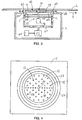
- Figure 3 is a schematic sectional side view of a possible embodiment of the second measuring head 4 used in the measuring equipment 1.
- Figure 4 is a top view of the second measuring head 4 of Figure 3 .
- the reference piece 12 is provided with a plural number of holes 19 arranged around the measurement point 14, at different distances from the measurement point 14, and extending through the reference piece 12. In other words, in the direction of travel of the web 2 these holes 19 are before and after the measurement point 14 and at the side of the measurement point 14.
- the measurement point 14 forms the area where the distance between the first sensor 10 and the moving paper web 2 is measured by means of the laser mentioned above, for example.
- the reference piece 12 in turn is placed to the other measuring head 4 in such a way that a substantially open air space 20 is left below the reference piece 12.
- the second measuring head 4 is provided with a feed conduit 21 and a nozzle gap 22 for feeding a gaseous medium between the second measuring head 4 and the paper web 2 and means, such as a blower 23 and a blower control unit 22 for controlling it, for feeding the gas into the feed conduit 21.
- Figure 1 does not show the valves used in the feeding of the gas.
- the feeding of the gas is depicted with arrows C.
- the gas to be fed is preferably air, although some other gas may be used as well.
- the gas to be fed into the feed conduit 21 flows from the feed conduit 21 into the nozzle gap 22.
- the feed conduit 21 is annular and so is the nozzle gap 22.
- the nozzle gap 22 is surrounded by a curved guide surface 25, the nozzle gap 22 and the curved guide surface 25 thus forming a kind of a Coanda nozzle.
- From the nozzle gap 22 the gas is discharged towards the paper web 2, the curved guide surface 25 in the immediate vicinity of the nozzle gap 22 diverting the gas so that it flows between the paper web 2 and the second measuring head 4.
- the gas thus flows as depicted by arrows C.
- the pressure of the gas and thereby its flow rate are adjusted to such a magnitude that the gas flowing between the paper web 2 and the second measuring head 4 creates a negative pressure. Due to the impact of the Coanda nozzle the negative pressure thus created acts on the air space 20 below the reference piece 12 and further through the holes 19 made into the reference piece 12 between the reference piece and the paper web 2 at the reference piece 12, the impact of this negative pressure thus causing the paper web 2 to become supported against the upper surface of the reference piece 12, i.e. against the reference surface 13.
- the curved guide surface 25 may be formed to a frame structure 26 of the second measuring head 4 surrounding the nozzle gap 22 or to a profile element 27 to be arranged around the nozzle gap 22, as shown in Figures 3 and 4 . Naturally the negative pressure can also be generated using a vacuum pump.
- the holes 19 formed through the reference piece 12 are positioned in the reference piece 12 in such a way that the moving paper web 2 sets straight and flat against the measurement point 14 in the reference piece 12.
- the holes 19 are dimensioned to be large enough for letting through dust and other impurities carried by the paper web 2, yet small enough so that the paper web 2 supported against the reference piece 12 cannot become blistered or wrinkled but sets evenly against the reference piece 12 and particularly against the measurement point 14.
- the negative pressure formed below the reference piece 12 may be used for enhancing the supporting of the moving paper web 2 against the reference piece 12 in such a way that vibrations possibly created at high web 2 speeds cannot detach the web 2 from the reference piece 12 at the measurement point 14.
- the web does not get blistered or wrinkled in any other way either but stays at the area of the measurement point 14, supported against the reference piece 12, thus allowing the calibration to be carried out even with the web 2 proceeding at a considerably high speed, because the web 2 cannot become detached from the reference piece 12 at the area of the measurement point 14.
- the feed pressure of the gas to be fed between the moving paper web 2 and the second measuring head 4 and thereby its flow rate may vary depending on the speed, tightness, grade or grammage of the paper web 2, for example.
- the flow rate of the gas may be changed for example by means of the blower 23 controlled by the blower control unit 24.
- the pressure difference that has to be created between the paper web 2 and the air space 20 for supporting the paper web 2 against the reference piece 2 is very small. Even an air space 20 pressure that is about one per cent lower than the pressure between the reference piece 12 and the paper web 2 is enough for supporting the web 2 to the reference piece 12 so that vibration or blistering is not formed in the web 2 at the measurement point 14.
- Figure 3 further shows schematically support members 28 allowing the reference piece 12 to be supported to the second measuring head 4 during a normal measuring operation in such a way that the reference piece 12 does not necessarily rest at all or solely on the shaft 17.
- the web 2 may be supported against the reference piece 12 also without the negative pressure for example by pressing the reference piece 12 against the web 2, whereby the tightness of the web 2 produces a sufficiently even contact between the web 2 and the reference piece 12. Further, the web 2 may be supported against the reference piece 12 for example by means of mechanical forcing or air guidance.
Landscapes
- Physics & Mathematics (AREA)
- General Physics & Mathematics (AREA)
- Length Measuring Devices With Unspecified Measuring Means (AREA)
- Length Measuring Devices By Optical Means (AREA)
Claims (27)
- Procédé pour étalonner un équipement de mesure (1) mesurant l'épaisseur d'une bande mobile (2), l'équipement de mesure (1) comprenant au moins un premier capteur (10), au moins un deuxième capteur (11) et au moins une pièce de référence (12),
caractérisé par les étapes consistant à :supporter la bande mobile (2) par la pièce de référence (12) ;déplacer la pièce de référence (12) et la bande mobile (2) supportée ainsi à différentes distances du premier capteur (10) et du deuxième capteur (11) ;mesurer une distance (D1) entre la bande mobile (2) et le premier capteur (10) au moyen du premier capteur (10) pour au moins deux distances (D1) différentes ;mesurer une distance (D2) entre la pièce de référence (12) et le deuxième capteur (11) au moyen du deuxième capteur (11) pour au moins deux distances (D2) différentes ; et étalonner le premier capteur (10) et le deuxième capteur (11) pour être uniformes par rapport au mouvement de la pièce de référence (12). - Procédé selon la revendication 1, caractérisé par l'étape consistant à créer une pression négative entre la bande mobile (2) et la pièce de référence (12) pour supporter la bande mobile (2) sur la pièce de référence (12).
- Procédé selon la revendication 1 ou 2, caractérisé en ce que la pièce de référence (12) est prévue avec un point de mesure (14), le premier capteur (10) étant configuré pour mesurer la première distance (D1) entre la bande mobile (2) et le premier capteur (10) depuis l'intérieur de la zone indiquée par le point de mesure (14) et en ce que la pièce de référence (12) est agencée sur l'équipement de mesure (1) de sorte qu'au-dessous de la pièce de référence (12), il y a un espace d'air sensiblement ouvert (20) et en ce que l'équipement de mesure comprend en outre des moyens pour créer une pression négative dans l'espace d'air (20) au-dessous de la pièce de référence (12) et en ce que la pièce de référence (20) est prévue avec des trous (19) perçant la pièce de référence à différentes distances du point de mesure (14) et en créant dans l'espace d'air (20), une pression négative qui agit à travers les trous (19) dans la pièce de référence entre la pièce de référence (12) et la bande mobile (2) de sorte que la bande mobile (2) est supportée contre la pièce de référence sensiblement au moins sur toute la zone du point de mesure (14).
- Procédé selon la revendication 3, caractérisé en ce que l'équipement de mesure (1) comprend une première tête de mesure (3) et une seconde tête de mesure (4) destinées à être placées sur les côtés opposés de la bande mobile (2) dans la direction de l'épaisseur de la bande (2) et en ce que le premier capteur (10) et le deuxième capteur (11) sont agencés dans la première tête de mesure (3) et la pièce de référence (12) est agencée dans la seconde tête de mesure (4) et en ce que la seconde tête de mesure (4) est prévue avec au moins un conduit (21) raccordé à l'espace d'air (20) au-dessous de la pièce de référence (12) et en ce qu'un milieu gazeux est alimenté entre la seconde tête de mesure (4) et la bande mobile (2) de sorte que l'alimentation du milieu gazeux provoque une pression négative dans l'espace d'air (20) et en outre à travers les trous (19) de la pièce de référence (12) entre la pièce de référence (12) et la bande mobile (2).
- Procédé selon la revendication 4, caractérisé en ce que le conduit (21) pour alimenter le milieu gazeux entre la seconde tête de mesure (4) et la bande mobile (2) comprend un espace de buse (22) entre la pièce de référence (12) et la structure de bâti (26) de la seconde tête de mesure (4) ou un élément de profilé (27) agencé sur la structure de bâti et en ce que le milieu gazeux est alimenté à partir de l'espace de buse (22) entre la seconde tête de mesure (4) et la bande mobile (2) le long des bords de la structure de bâti (26) de la seconde tête de mesure (4) ou ceux de l'élément de profilé (27) agencé sur la structure de bâti.
- Procédé selon la revendication 5, caractérisé en ce que la structure de bâti (26) de la seconde tête de mesure (4) ou de l'élément de profilé (27) agencé sur cette dernière, comprend une surface de guidage incurvée (25) pour dévier le milieu gazeux afin qu'il s'écoule entre la seconde tête de mesure (4) et la bande mobile (2).
- Procédé selon l'une quelconque des revendications 4 à 6, caractérisé en ce que le milieu gazeux est de l'air.
- Procédé selon l'une quelconque des revendications précédentes, caractérisé en ce que l'équipement de mesure (1) comprend en outre au moins un troisième capteur et en ce que la distance de la bande mobile (2) et du troisième capteur est mesurée dans la direction de l'épaisseur de la bande (2) à partir de son côté opposé par rapport au premier capteur (10) et en ce que le premier capteur (10), le deuxième capteur (11) et le troisième capteur sont étalonnés pour être uniformes par rapport au mouvement de la pièce de référence (12).
- Procédé selon l'une quelconque des revendications précédentes, caractérisé par l'étape consistant à mesurer la distance entre le premier capteur (10) et la bande mobile (2) par voie optique.
- Procédé selon l'une quelconque des revendications précédentes, caractérisé par l'étape consistant à mesurer la distance (D2) entre le deuxième capteur (11) et la pièce de référence (12) par voie inductive, capacitive ou par un autre moyen dans lequel la mesure est prise à travers la bande mobile (2).
- Procédé selon l'une quelconque des revendications 8 à 10, caractérisé par l'étape consistant à mesurer la distance entre le troisième capteur et la bande mobile (2) par voie optique.
- Procédé selon l'une quelconque des revendications précédentes, caractérisé en ce que l'équipement de mesure (1) comprend en outre un actionneur (16) et un arbre (17) agencé entre l'actionneur (16) et la pièce de référence (12) et en ce que la pièce de référence (12) est déplacée par rapport aux capteurs (10, 11) avec l'arbre (17) à l'aide de l'actionneur (16).
- Procédé selon l'une quelconque des revendications précédentes, caractérisé en ce que la bande mobile est une bande de papier (2), une bande de carton, une bande de tissu ou une bande de pâte à papier.
- Equipement de mesure (1) pour mesurer l'épaisseur d'une bande mobile (2), l'équipement de mesure (1) comprenant au moins un premier capteur (10), au moins un deuxième capteur (11) et au moins une pièce de référence (12),
caractérisé en ce que :la pièce de référence est agencée pour supporter la bande mobile (2) ;la pièce de référence (12) est agencée pour être déplacée à différentes distances du premier capteur (10) et du deuxième capteur (11) ;le premier capteur (10) est agencé pour mesurer une distance (D1) entre la bande mobile (2) et le premier capteur (10) pour au moins deux distances (D1) différentes ; le deuxième capteur (11) est agencé pour mesurer une distance (D2) entre la pièce de référence (12) et le deuxième capteur (11) pour au moins deux distances différentes (D2) ; et en ce que :l'équipement de mesure (1) comprend en outre une unité de traitement de données (18) configurée pour étalonner le premier capteur (10) et le deuxième capteur (11) afin d'être uniformes par rapport au mouvement de la pièce de référence (12) et par rapport à la bande (2) qui est fabriquée. - Equipement de mesure selon la revendication 14, caractérisé en ce que :l'équipement de mesure (1) comprend en outre un actionneur (16) et un arbre (17) agencé entre l'actionneur (16) et la pièce de référence (12) pour déplacer la pièce de référence (12) avec l'arbre (17) à l'aide de l'actionneur (16).
- Equipement de mesure selon la revendication 15, caractérisé en ce que l'actionneur est un moteur pas à pas (16).
- Equipement de mesure selon l'une quelconque des revendications 14 à 16, caractérisé en ce que l'équipement de mesure (1) comprend des moyens pour créer une pression négative entre la bande mobile (2) et la pièce de référence (12) pour amener la bande mobile (2) en contact avec la pièce de référence (12).
- Equipement de mesure selon l'une quelconque des revendications 14 à 17, caractérisé en ce que la pièce de référence (12) est prévue avec un point de mesure (14), le premier capteur (10) étant agencé pour mesurer la distance (D1) entre la bande mobile (2) et le premier capteur (10) depuis l'intérieur de la zone indiquée par le point de mesure (14) et en ce que la pièce de référence (12) est agencée sur l'équipement de mesure (1) de sorte qu'au-dessous de la pièce de référence (12), il y a un espace d'air (20) sensiblement ouvert et en ce que l'équipement de mesure (20) comprend en outre des moyens pour créer une pression négative dans l'espace d'air (20) au-dessous de la pièce de référence (12) et en ce que la pièce de référence (12) est prévue avec des trous (19) perçant la pièce de référence à différentes distances du point de mesure (14) de sorte que la pression négative à créer dans l'espace d'air (20) est agencée pour agir entre la pièce de référence (12) et la bande mobile (2) à travers les trous (19) réalisés sur la pièce de référence (12) de sorte que la bande mobile (2) est supportée sur la pièce de référence (12) sensiblement au moins sur toute la zone du point de mesure.
- Equipement de mesure selon la revendication 18, caractérisé en ce que l'équipement de mesure (1) comprend une première tête de mesure (3) et une seconde tête de mesure (4) destinées à être placées sur les côtés opposés de la bande mobile (2) dans la direction de l'épaisseur de la bande (2) et en ce que le premier capteur (10) et le deuxième capteur (11) sont agencés dans la première tête de mesure (3) et la pièce de référence (12) est agencée dans la seconde tête de mesure (4) et en ce que la seconde tête de mesure (4) est prévue avec au moins un conduit (21) raccordé à l'espace d'air (20) au-dessous de la pièce de référence (12), le conduit (21) étant configuré pour alimenter un milieu gazeux entre la seconde tête de mesure (4) et la bande mobile (2) de sorte que l'alimentation du milieu gazeux est agencé pour créer une pression négative dans l'espace d'air (20) et en outre entre la pièce de référence (12) et la bande mobile (2) à travers les trous (19) dans la pièce de référence (12).
- Equipement de mesure selon la revendication 19, caractérisé en ce que le conduit (21) pour alimenter le milieu gazeux entre la seconde tête de mesure (4) et la bande mobile (2) comprend un espace de buse (22) agencé entre la pièce de référence (12) et une structure de bâti (26) de la seconde tête de mesure (4) ou un élément de profilé (27) agencé sur la structure de bâti, le milieu gazeux étant agencé pour être alimenté à partir de l'espace de buse (22) entre la seconde tête de mesure (4) et la bande mobile (2) le long des bords de la structure de bâti (26) de la seconde tête de mesure (4) ou ceux de l'élément de profilé (27) agencé sur la structure de bâti.
- Equipement de mesure selon la revendication 20, caractérisé en ce que la structure de bâti (26) de la seconde tête de mesure (4) ou de l'élément de profilé (27) agencé sur cette dernière, comprend une surface de guidage incurvée (25) pour dévier le milieu gazeux afin qu'il s'écoule entre la seconde tête de mesure (4) et la bande mobile (2).
- Equipement de mesure selon l'une quelconque des revendications 19 à 21, caractérisé en ce que le milieu gazeux est de l'air.
- Equipement de mesure selon l'une quelconque des revendications précédentes, caractérisé en ce que l'équipement de mesure (1) comprend en outre au moins un troisième capteur configuré pour mesurer la distance de la bande mobile (2) et du troisième capteur dans la direction d'épaisseur de la bande (2) sur son côté opposé par rapport au premier capteur (10) et en ce que l'unité de traitement de données (18) est configurée pour étalonner le premier capteur, le deuxième capteur et le troisième capteur pour qu'ils soient uniformes par rapport au mouvement de la pièce de référence (12).
- Equipement de mesure selon l'une quelconque des revendications 14 à 23, caractérisé en ce que le premier capteur (10) comprend un laser agencé pour mesurer, par voie optique, la distance (D1) entre le premier capteur (10) et la bande mobile (2).
- Equipement de mesure selon l'une quelconque des revendications 14 à 24, caractérisé en ce que le deuxième capteur (11) comprend une bobine agencée pour mesurer, par voie inductive, la distance (D2) entre le deuxième capteur (11) et la pièce de référence (12).
- Equipement de mesure selon l'une quelconque des revendications 23 à 25, caractérisé en ce que le troisième capteur comprend un laser agencé pour mesurer, par voie optique, la distance entre le troisième capteur et la bande mobile.
- Equipement de mesure selon l'une quelconque des revendications précédentes, caractérisé en ce que la bande mobile (2) est une bande de papier (2), une bande de carton, une bande de tissu ou une bande de pâte à papier.
Applications Claiming Priority (2)
| Application Number | Priority Date | Filing Date | Title |
|---|---|---|---|
| FI20065160A FI119260B (fi) | 2006-03-10 | 2006-03-10 | Menetelmä mittauslaitteiston kalibroimiseksi ja mittauslaitteisto |
| PCT/FI2007/050124 WO2007104833A1 (fr) | 2006-03-10 | 2007-03-07 | Procede d'etalonnage d'equipement de mesure et equipement de mesure |
Publications (2)
| Publication Number | Publication Date |
|---|---|
| EP2002202A1 EP2002202A1 (fr) | 2008-12-17 |
| EP2002202B1 true EP2002202B1 (fr) | 2017-05-31 |
Family
ID=36192005
Family Applications (1)
| Application Number | Title | Priority Date | Filing Date |
|---|---|---|---|
| EP07730625.6A Active EP2002202B1 (fr) | 2006-03-10 | 2007-03-07 | Procede d'etalonnage d'equipement de mesure et equipement de mesure |
Country Status (4)
| Country | Link |
|---|---|
| US (1) | US8117891B2 (fr) |
| EP (1) | EP2002202B1 (fr) |
| FI (1) | FI119260B (fr) |
| WO (1) | WO2007104833A1 (fr) |
Families Citing this family (18)
| Publication number | Priority date | Publication date | Assignee | Title |
|---|---|---|---|---|
| WO2009032094A1 (fr) * | 2007-08-31 | 2009-03-12 | Abb Ltd. | Dispositif de mesure de l'épaisseur d'une bande |
| US9045306B2 (en) * | 2007-11-27 | 2015-06-02 | Abb Ltd. | Sheet stabilizer with suction nozzle having center protrusion |
| FI20075975L (fi) * | 2007-12-31 | 2009-07-01 | Metso Automation Oy | Rainan mittaus |
| GB2479572A (en) * | 2010-04-15 | 2011-10-19 | Paul Roderick Hayes Griffin | Thickness guage for measurement of hot metal plate on the procss line |
| DE102011107771B4 (de) * | 2011-04-15 | 2013-10-17 | Micro-Epsilon Messtechnik Gmbh & Co. Kg | Vorrichtung und Verfahren zur Dickenmessung eines Messobjekts |
| DE102011106523A1 (de) * | 2011-07-04 | 2013-01-10 | Giesecke & Devrient Gmbh | Prüfgerät und Verfahren zur Kalibrierung eines Prüfgeräts |
| WO2013007864A1 (fr) * | 2011-07-08 | 2013-01-17 | Metso Automation Oy | Procédé et dispositif de mesure destinés à mesurer l'épaisseur d'une bande fibreuse mobile |
| WO2013026791A1 (fr) * | 2011-08-22 | 2013-02-28 | Windmöller & Hölscher Kg | Machine et procédé d'impression de bandes d'impression |
| FI125811B (en) * | 2013-05-29 | 2016-02-29 | Valmet Automation Oy | Web measurement |
| JP6337538B2 (ja) * | 2014-03-18 | 2018-06-06 | セイコーエプソン株式会社 | 画像記録装置、キャリブレーション方法および画像記録方法 |
| US9753114B2 (en) * | 2014-11-03 | 2017-09-05 | Honeywell Limited | Gap and displacement magnetic sensor system for scanner heads in paper machines or other systems |
| WO2016177369A1 (fr) * | 2015-05-05 | 2016-11-10 | Micro-Epsilon Messtechnik Gmbh & Co. Kg | Dispositif et procédé de mesure de la largeur et de l'épaisseur d'un objet plan |
| US10641758B2 (en) | 2015-09-01 | 2020-05-05 | Exxonmobil Upstream Research Company | Apparatus, systems, and methods for enhancing hydrocarbon extraction and techniques related thereto |
| JP2018090344A (ja) * | 2016-11-30 | 2018-06-14 | コニカミノルタ株式会社 | 用紙搬送装置、画像形成装置、用紙の坪量の推定方法、および用紙の坪量の推定プログラム |
| IT201700042506A1 (it) * | 2017-04-18 | 2018-10-18 | Btsr Int Spa | Metodo, sistema e sensore per rilevare una caratteristica di un filo tessile o metallico alimentato ad una macchina operatrice |
| CN109238092A (zh) * | 2018-09-14 | 2019-01-18 | 佛山市恒力泰机械有限公司 | 陶瓷砖坯厚度在线自动检测方法及装置 |
| TWI755842B (zh) * | 2020-09-04 | 2022-02-21 | 奈米趨勢科技有限公司 | 非接觸式塑膠吹袋機薄膜厚度量測裝置 |
| CN117906509B (zh) * | 2024-01-16 | 2024-07-26 | 山东力强钢板有限公司 | 一种钢板厚度差激光测量装置及测量方法 |
Family Cites Families (9)
| Publication number | Priority date | Publication date | Assignee | Title |
|---|---|---|---|---|
| JPS60114709A (ja) | 1983-11-28 | 1985-06-21 | Yokohama Rubber Co Ltd:The | 絶縁物の厚み測定装置 |
| JPH01155204A (ja) | 1987-12-14 | 1989-06-19 | Yokogawa Electric Corp | 厚さ測定装置の校正方法 |
| JPH01156615A (ja) | 1987-12-15 | 1989-06-20 | Yokogawa Electric Corp | 厚さ測定装置の校正方法 |
| US5355083A (en) | 1988-11-16 | 1994-10-11 | Measurex Corporation | Non-contact sensor and method using inductance and laser distance measurements for measuring the thickness of a layer of material overlaying a substrate |
| US5062298A (en) | 1989-12-05 | 1991-11-05 | E. I. Du Pont De Nemours And Company | Non-contact wet or dry film thickness measuring device using eddy current and ultrasonic sensors |
| US5485082A (en) | 1990-04-11 | 1996-01-16 | Micro-Epsilon Messtechnik Gmbh & Co. Kg | Method of calibrating a thickness measuring device and device for measuring or monitoring the thickness of layers, tapes, foils, and the like |
| US6281679B1 (en) | 1998-12-21 | 2001-08-28 | Honeywell - Measurex | Web thickness measurement system |
| FI114337B (fi) | 2001-07-03 | 2004-09-30 | Metso Automation Oy | Menetelmä ja mittalaite liikkuvan rainan ainakin yhden ominaisuuden mittaamiseksi |
| US6967726B2 (en) | 2003-10-03 | 2005-11-22 | Honeywell International Inc. | Means for in-place automated calibration of optically-based thickness sensor |
-
2006
- 2006-03-10 FI FI20065160A patent/FI119260B/fi active IP Right Grant
-
2007
- 2007-03-07 EP EP07730625.6A patent/EP2002202B1/fr active Active
- 2007-03-07 WO PCT/FI2007/050124 patent/WO2007104833A1/fr not_active Ceased
- 2007-03-07 US US12/282,316 patent/US8117891B2/en active Active
Also Published As
| Publication number | Publication date |
|---|---|
| FI20065160L (fi) | 2007-09-11 |
| EP2002202A1 (fr) | 2008-12-17 |
| FI119260B (fi) | 2008-09-15 |
| WO2007104833A1 (fr) | 2007-09-20 |
| US8117891B2 (en) | 2012-02-21 |
| FI20065160A0 (fi) | 2006-03-10 |
| US20090056412A1 (en) | 2009-03-05 |
Similar Documents
| Publication | Publication Date | Title |
|---|---|---|
| US8117891B2 (en) | Method for calibration of measuring equipment and measuring equipment | |
| EP1273879B1 (fr) | Méthode et appareil pour mesurer au moins une propriété d'une bande en mouvement | |
| US7797985B2 (en) | Method and system for operating an air gauge at programmable or constant standoff | |
| US8760669B2 (en) | Method of measuring the thickness of a moving web | |
| JP2010260105A (ja) | 所定の半径で細長いワークピースを連続的に曲げるための装置 | |
| US20040221465A1 (en) | Method and apparatus using a closed loop controlled actuator for surface profilometry | |
| KR102375416B1 (ko) | 저항 측정 장치, 필름 제조 장치 및 도전성 필름의 제조 방법 | |
| US7319521B2 (en) | Measuring device | |
| KR20130118863A (ko) | 벨트 조정 방법 및 벨트 운반 시스템 | |
| KR20100123820A (ko) | 시트의 처짐 평가방법 및 평가장치 | |
| JP2006212765A (ja) | 工作機械の熱変位補正方法 | |
| CN101196391A (zh) | 表面形状测定装置 | |
| JP4629026B2 (ja) | 圧力センサ | |
| US10184784B2 (en) | Device and method for measuring the width and thickness of a flat object | |
| WO2013007864A1 (fr) | Procédé et dispositif de mesure destinés à mesurer l'épaisseur d'une bande fibreuse mobile | |
| WO2009156566A1 (fr) | Procédé et dispositif pour calibrer la position des lames d’une bobineuse-trancheuse dans une machine à bande fibreuse | |
| KR20160083221A (ko) | 선형 위치 결정 장치 및 이의 오차 보상 방법 | |
| JP4291313B2 (ja) | ヘッド作動制御装置及び制御方法及びステージ装置 | |
| JP4402078B2 (ja) | ステージ装置 | |
| CN116604202A (zh) | 一种激光头距离感应器的精确校准控制方法与系统 | |
| JP5102437B2 (ja) | 鋼板の平面形状計測方法および装置 | |
| US20140067090A1 (en) | Movable device allowing instantaneous correction of error in moving state and error correction method thereof | |
| CN201613477U (zh) | 进给系统温升量测与补偿装置 | |
| Kim et al. | A precise position measurement system of roll-to-roll printing using burst alignment patterns | |
| US20260102976A1 (en) | Adjustment method, coating element, and additive manufacturing device |
Legal Events
| Date | Code | Title | Description |
|---|---|---|---|
| PUAI | Public reference made under article 153(3) epc to a published international application that has entered the european phase |
Free format text: ORIGINAL CODE: 0009012 |
|
| 17P | Request for examination filed |
Effective date: 20081006 |
|
| AK | Designated contracting states |
Kind code of ref document: A1 Designated state(s): AT BE BG CH CY CZ DE DK EE ES FI FR GB GR HU IE IS IT LI LT LU LV MC MT NL PL PT RO SE SI SK TR |
|
| 17Q | First examination report despatched |
Effective date: 20090211 |
|
| DAX | Request for extension of the european patent (deleted) | ||
| GRAP | Despatch of communication of intention to grant a patent |
Free format text: ORIGINAL CODE: EPIDOSNIGR1 |
|
| INTG | Intention to grant announced |
Effective date: 20161125 |
|
| RAP1 | Party data changed (applicant data changed or rights of an application transferred) |
Owner name: METSO AUTOMATION OY |
|
| GRAS | Grant fee paid |
Free format text: ORIGINAL CODE: EPIDOSNIGR3 |
|
| RAP1 | Party data changed (applicant data changed or rights of an application transferred) |
Owner name: VALMET AUTOMATION OY |
|
| GRAA | (expected) grant |
Free format text: ORIGINAL CODE: 0009210 |
|
| AK | Designated contracting states |
Kind code of ref document: B1 Designated state(s): AT BE BG CH CY CZ DE DK EE ES FI FR GB GR HU IE IS IT LI LT LU LV MC MT NL PL PT RO SE SI SK TR |
|
| REG | Reference to a national code |
Ref country code: CH Ref legal event code: EP Ref country code: GB Ref legal event code: FG4D |
|
| REG | Reference to a national code |
Ref country code: AT Ref legal event code: REF Ref document number: 897891 Country of ref document: AT Kind code of ref document: T Effective date: 20170615 |
|
| REG | Reference to a national code |
Ref country code: IE Ref legal event code: FG4D |
|
| REG | Reference to a national code |
Ref country code: DE Ref legal event code: R096 Ref document number: 602007051157 Country of ref document: DE |
|
| REG | Reference to a national code |
Ref country code: NL Ref legal event code: MP Effective date: 20170531 |
|
| REG | Reference to a national code |
Ref country code: LT Ref legal event code: MG4D |
|
| REG | Reference to a national code |
Ref country code: AT Ref legal event code: MK05 Ref document number: 897891 Country of ref document: AT Kind code of ref document: T Effective date: 20170531 |
|
| PG25 | Lapsed in a contracting state [announced via postgrant information from national office to epo] |
Ref country code: GR Free format text: LAPSE BECAUSE OF FAILURE TO SUBMIT A TRANSLATION OF THE DESCRIPTION OR TO PAY THE FEE WITHIN THE PRESCRIBED TIME-LIMIT Effective date: 20170901 Ref country code: ES Free format text: LAPSE BECAUSE OF FAILURE TO SUBMIT A TRANSLATION OF THE DESCRIPTION OR TO PAY THE FEE WITHIN THE PRESCRIBED TIME-LIMIT Effective date: 20170531 Ref country code: LT Free format text: LAPSE BECAUSE OF FAILURE TO SUBMIT A TRANSLATION OF THE DESCRIPTION OR TO PAY THE FEE WITHIN THE PRESCRIBED TIME-LIMIT Effective date: 20170531 Ref country code: AT Free format text: LAPSE BECAUSE OF FAILURE TO SUBMIT A TRANSLATION OF THE DESCRIPTION OR TO PAY THE FEE WITHIN THE PRESCRIBED TIME-LIMIT Effective date: 20170531 Ref country code: FI Free format text: LAPSE BECAUSE OF FAILURE TO SUBMIT A TRANSLATION OF THE DESCRIPTION OR TO PAY THE FEE WITHIN THE PRESCRIBED TIME-LIMIT Effective date: 20170531 |
|
| PG25 | Lapsed in a contracting state [announced via postgrant information from national office to epo] |
Ref country code: SE Free format text: LAPSE BECAUSE OF FAILURE TO SUBMIT A TRANSLATION OF THE DESCRIPTION OR TO PAY THE FEE WITHIN THE PRESCRIBED TIME-LIMIT Effective date: 20170531 Ref country code: BG Free format text: LAPSE BECAUSE OF FAILURE TO SUBMIT A TRANSLATION OF THE DESCRIPTION OR TO PAY THE FEE WITHIN THE PRESCRIBED TIME-LIMIT Effective date: 20170831 Ref country code: LV Free format text: LAPSE BECAUSE OF FAILURE TO SUBMIT A TRANSLATION OF THE DESCRIPTION OR TO PAY THE FEE WITHIN THE PRESCRIBED TIME-LIMIT Effective date: 20170531 Ref country code: IS Free format text: LAPSE BECAUSE OF FAILURE TO SUBMIT A TRANSLATION OF THE DESCRIPTION OR TO PAY THE FEE WITHIN THE PRESCRIBED TIME-LIMIT Effective date: 20170930 Ref country code: NL Free format text: LAPSE BECAUSE OF FAILURE TO SUBMIT A TRANSLATION OF THE DESCRIPTION OR TO PAY THE FEE WITHIN THE PRESCRIBED TIME-LIMIT Effective date: 20170531 |
|
| PG25 | Lapsed in a contracting state [announced via postgrant information from national office to epo] |
Ref country code: EE Free format text: LAPSE BECAUSE OF FAILURE TO SUBMIT A TRANSLATION OF THE DESCRIPTION OR TO PAY THE FEE WITHIN THE PRESCRIBED TIME-LIMIT Effective date: 20170531 Ref country code: DK Free format text: LAPSE BECAUSE OF FAILURE TO SUBMIT A TRANSLATION OF THE DESCRIPTION OR TO PAY THE FEE WITHIN THE PRESCRIBED TIME-LIMIT Effective date: 20170531 Ref country code: RO Free format text: LAPSE BECAUSE OF FAILURE TO SUBMIT A TRANSLATION OF THE DESCRIPTION OR TO PAY THE FEE WITHIN THE PRESCRIBED TIME-LIMIT Effective date: 20170531 Ref country code: SK Free format text: LAPSE BECAUSE OF FAILURE TO SUBMIT A TRANSLATION OF THE DESCRIPTION OR TO PAY THE FEE WITHIN THE PRESCRIBED TIME-LIMIT Effective date: 20170531 Ref country code: CZ Free format text: LAPSE BECAUSE OF FAILURE TO SUBMIT A TRANSLATION OF THE DESCRIPTION OR TO PAY THE FEE WITHIN THE PRESCRIBED TIME-LIMIT Effective date: 20170531 |
|
| PG25 | Lapsed in a contracting state [announced via postgrant information from national office to epo] |
Ref country code: PL Free format text: LAPSE BECAUSE OF FAILURE TO SUBMIT A TRANSLATION OF THE DESCRIPTION OR TO PAY THE FEE WITHIN THE PRESCRIBED TIME-LIMIT Effective date: 20170531 Ref country code: IT Free format text: LAPSE BECAUSE OF FAILURE TO SUBMIT A TRANSLATION OF THE DESCRIPTION OR TO PAY THE FEE WITHIN THE PRESCRIBED TIME-LIMIT Effective date: 20170531 |
|
| REG | Reference to a national code |
Ref country code: DE Ref legal event code: R097 Ref document number: 602007051157 Country of ref document: DE |
|
| PLBE | No opposition filed within time limit |
Free format text: ORIGINAL CODE: 0009261 |
|
| STAA | Information on the status of an ep patent application or granted ep patent |
Free format text: STATUS: NO OPPOSITION FILED WITHIN TIME LIMIT |
|
| 26N | No opposition filed |
Effective date: 20180301 |
|
| PG25 | Lapsed in a contracting state [announced via postgrant information from national office to epo] |
Ref country code: SI Free format text: LAPSE BECAUSE OF FAILURE TO SUBMIT A TRANSLATION OF THE DESCRIPTION OR TO PAY THE FEE WITHIN THE PRESCRIBED TIME-LIMIT Effective date: 20170531 |
|
| REG | Reference to a national code |
Ref country code: CH Ref legal event code: PL |
|
| GBPC | Gb: european patent ceased through non-payment of renewal fee |
Effective date: 20180307 |
|
| PG25 | Lapsed in a contracting state [announced via postgrant information from national office to epo] |
Ref country code: MC Free format text: LAPSE BECAUSE OF FAILURE TO SUBMIT A TRANSLATION OF THE DESCRIPTION OR TO PAY THE FEE WITHIN THE PRESCRIBED TIME-LIMIT Effective date: 20170531 |
|
| REG | Reference to a national code |
Ref country code: BE Ref legal event code: MM Effective date: 20180331 |
|
| REG | Reference to a national code |
Ref country code: IE Ref legal event code: MM4A |
|
| PG25 | Lapsed in a contracting state [announced via postgrant information from national office to epo] |
Ref country code: LU Free format text: LAPSE BECAUSE OF NON-PAYMENT OF DUE FEES Effective date: 20180307 |
|
| PG25 | Lapsed in a contracting state [announced via postgrant information from national office to epo] |
Ref country code: IE Free format text: LAPSE BECAUSE OF NON-PAYMENT OF DUE FEES Effective date: 20180307 |
|
| PG25 | Lapsed in a contracting state [announced via postgrant information from national office to epo] |
Ref country code: BE Free format text: LAPSE BECAUSE OF NON-PAYMENT OF DUE FEES Effective date: 20180331 Ref country code: GB Free format text: LAPSE BECAUSE OF NON-PAYMENT OF DUE FEES Effective date: 20180307 Ref country code: LI Free format text: LAPSE BECAUSE OF NON-PAYMENT OF DUE FEES Effective date: 20180331 Ref country code: CH Free format text: LAPSE BECAUSE OF NON-PAYMENT OF DUE FEES Effective date: 20180331 |
|
| PG25 | Lapsed in a contracting state [announced via postgrant information from national office to epo] |
Ref country code: FR Free format text: LAPSE BECAUSE OF NON-PAYMENT OF DUE FEES Effective date: 20180331 |
|
| PG25 | Lapsed in a contracting state [announced via postgrant information from national office to epo] |
Ref country code: MT Free format text: LAPSE BECAUSE OF NON-PAYMENT OF DUE FEES Effective date: 20180307 |
|
| PG25 | Lapsed in a contracting state [announced via postgrant information from national office to epo] |
Ref country code: TR Free format text: LAPSE BECAUSE OF FAILURE TO SUBMIT A TRANSLATION OF THE DESCRIPTION OR TO PAY THE FEE WITHIN THE PRESCRIBED TIME-LIMIT Effective date: 20170531 |
|
| PG25 | Lapsed in a contracting state [announced via postgrant information from national office to epo] |
Ref country code: HU Free format text: LAPSE BECAUSE OF FAILURE TO SUBMIT A TRANSLATION OF THE DESCRIPTION OR TO PAY THE FEE WITHIN THE PRESCRIBED TIME-LIMIT; INVALID AB INITIO Effective date: 20070307 Ref country code: PT Free format text: LAPSE BECAUSE OF FAILURE TO SUBMIT A TRANSLATION OF THE DESCRIPTION OR TO PAY THE FEE WITHIN THE PRESCRIBED TIME-LIMIT Effective date: 20170531 |
|
| PG25 | Lapsed in a contracting state [announced via postgrant information from national office to epo] |
Ref country code: CY Free format text: LAPSE BECAUSE OF FAILURE TO SUBMIT A TRANSLATION OF THE DESCRIPTION OR TO PAY THE FEE WITHIN THE PRESCRIBED TIME-LIMIT Effective date: 20170531 |
|
| PGFP | Annual fee paid to national office [announced via postgrant information from national office to epo] |
Ref country code: DE Payment date: 20250319 Year of fee payment: 19 |