EP2002114B1 - Filterelement in einem kraftstoffinjektor - Google Patents
Filterelement in einem kraftstoffinjektor Download PDFInfo
- Publication number
- EP2002114B1 EP2002114B1 EP07726349A EP07726349A EP2002114B1 EP 2002114 B1 EP2002114 B1 EP 2002114B1 EP 07726349 A EP07726349 A EP 07726349A EP 07726349 A EP07726349 A EP 07726349A EP 2002114 B1 EP2002114 B1 EP 2002114B1
- Authority
- EP
- European Patent Office
- Prior art keywords
- filter element
- fuel
- fuel injector
- actuator
- injector
- Prior art date
- Legal status (The legal status is an assumption and is not a legal conclusion. Google has not performed a legal analysis and makes no representation as to the accuracy of the status listed.)
- Not-in-force
Links
- 239000000446 fuel Substances 0.000 title claims abstract description 67
- 238000002485 combustion reaction Methods 0.000 description 14
- 230000006835 compression Effects 0.000 description 3
- 238000007906 compression Methods 0.000 description 3
- 230000008878 coupling Effects 0.000 description 3
- 238000010168 coupling process Methods 0.000 description 3
- 238000005859 coupling reaction Methods 0.000 description 3
- 230000000694 effects Effects 0.000 description 3
- 238000001914 filtration Methods 0.000 description 2
- 239000012535 impurity Substances 0.000 description 2
- 238000002347 injection Methods 0.000 description 1
- 239000007924 injection Substances 0.000 description 1
- 238000009413 insulation Methods 0.000 description 1
- 238000007789 sealing Methods 0.000 description 1
Images

Classifications
-
- F—MECHANICAL ENGINEERING; LIGHTING; HEATING; WEAPONS; BLASTING
- F02—COMBUSTION ENGINES; HOT-GAS OR COMBUSTION-PRODUCT ENGINE PLANTS
- F02M—SUPPLYING COMBUSTION ENGINES IN GENERAL WITH COMBUSTIBLE MIXTURES OR CONSTITUENTS THEREOF
- F02M51/00—Fuel-injection apparatus characterised by being operated electrically
- F02M51/06—Injectors peculiar thereto with means directly operating the valve needle
- F02M51/0603—Injectors peculiar thereto with means directly operating the valve needle using piezoelectric or magnetostrictive operating means
-
- F—MECHANICAL ENGINEERING; LIGHTING; HEATING; WEAPONS; BLASTING
- F02—COMBUSTION ENGINES; HOT-GAS OR COMBUSTION-PRODUCT ENGINE PLANTS
- F02M—SUPPLYING COMBUSTION ENGINES IN GENERAL WITH COMBUSTIBLE MIXTURES OR CONSTITUENTS THEREOF
- F02M47/00—Fuel-injection apparatus operated cyclically with fuel-injection valves actuated by fluid pressure
- F02M47/02—Fuel-injection apparatus operated cyclically with fuel-injection valves actuated by fluid pressure of accumulator-injector type, i.e. having fuel pressure of accumulator tending to open, and fuel pressure in other chamber tending to close, injection valves and having means for periodically releasing that closing pressure
-
- F—MECHANICAL ENGINEERING; LIGHTING; HEATING; WEAPONS; BLASTING
- F02—COMBUSTION ENGINES; HOT-GAS OR COMBUSTION-PRODUCT ENGINE PLANTS
- F02M—SUPPLYING COMBUSTION ENGINES IN GENERAL WITH COMBUSTIBLE MIXTURES OR CONSTITUENTS THEREOF
- F02M61/00—Fuel-injectors not provided for in groups F02M39/00 - F02M57/00 or F02M67/00
- F02M61/16—Details not provided for in, or of interest apart from, the apparatus of groups F02M61/02 - F02M61/14
- F02M61/165—Filtering elements specially adapted in fuel inlets to injector
Definitions
- the invention relates to a fuel injector according to the preamble of claim 1, such as in the JP 8218974 shown.
- the high-pressure fuel connection has a bore in which a rod filter is arranged, which prevents impurities from entering the injector.
- the object of the invention is to provide a fuel injector according to the preamble of claim 1, which has an improved filtering effect.
- the object relates to a fuel injector with an injector housing which comprises a high-pressure fuel connection and a high-pressure actor receiving space in which an actuator is arranged is, and with a filter element, wherein the filter element is arranged in the Injektorgephaseuse.
- the invention is characterized in that the filter element is arranged in the radial direction between the actuator and the Injektorgeophuse and has the shape of a sleeve having a plurality of small through holes, which are flowed through during operation of the fuel injector of high-pressure fuel.
- This has the advantage that the filter element provides a large effective filter area without requiring much space. The flow through the filter element takes place in the radial direction from the inside to the outside or from the outside inwards.
- the diameter of the through holes is 20 to 40 microns.
- the through-holes are preferably formed by bores which extend substantially in the radial direction.
- the holes are preferably drilled by means of a laser device.
- a further preferred exemplary embodiment of the fuel injector is characterized in that the high-pressure fuel port is in communication with an annular space which extends between the filter element and the injector housing. Through the high-pressure fuel port, the fuel passes into the annulus and from there through the filter element.
- Another preferred exemplary embodiment of the fuel injector is characterized in that a further annular space extends between the filter element and the actuator. Through the further annular space of the filtered fuel passes into the interior of the injector.
- the high-pressure fuel port is connected to an annular space which extends between the actuator and the filter element. Through the high-pressure fuel port, the fuel passes into the annulus and from there through the filter element.
- a further preferred embodiment of the fuel injector is characterized in that the filter element has at one end a feed hopper into which a high-pressure fuel channel opens, which starts from the high-pressure fuel port.
- the feed hopper is preferably integrally connected to the filter element.
- Another preferred exemplary embodiment of the fuel injector is characterized in that a further annular space extends between the filter element and the injector housing. Through the further annular space of the filtered fuel passes into the interior of the injector.
- a further preferred embodiment of the fuel injector is characterized in that a guide ring is attached to at least one end of the filter element.
- the guide ring may extend radially inwardly or radially outwardly from the filter element. When the guide ring extends radially outwardly, it preferably abuts against the injector housing. When the guide ring extends radially inwardly, it preferably abuts against an actuator piston.
- the filter element is acted upon at one end in the axial direction with the biasing force of a spring device. The other end of the filter element is preferably against the injector housing.
- a further preferred embodiment of the fuel injector is characterized in that the annular space and / or the further annular space in the radial direction has an extension of 100 to 200 microns / has.
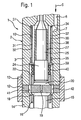
- FIG. 1 is a section of a fuel injector 1 with an injector 2 shown in longitudinal section.
- the injector housing 2 comprises an injector body 3, which is also referred to as a holding body.
- a high-pressure fuel connection is indicated, passes through the high-pressure fuel in a high-pressure fuel passage 6, which is recessed in the holding body 3.
- the high-pressure fuel channel 6 opens into an orifice region 7 in a main bore 10, which extends in the interior of the holding body 3 in the longitudinal direction.
- the main bore 10 of the injector body or holding body 3 is closed by an intermediate plate 12.
- the intermediate plate 12 is clamped by means of a clamping nut 13 between a nozzle body 14 and the holding body 3.
- the nozzle body 14 protrudes with its lower end shown cut off into the combustion chamber of an internal combustion engine to be supplied with fuel.
- an axial guide bore is recessed, in which a nozzle needle 15 is guided axially displaceable.
- At the combustion chamber near the end of the nozzle needle 15 at least one injection hole is provided in a known manner, is injected by the high-pressure fuel from the nozzle body 14 into the combustion chamber of the internal combustion engine when the nozzle needle 15 lifts with its tip from an associated nozzle needle seat.
- a control chamber limiting sleeve 16 is guided under sealing action, which limits a control chamber 18.
- the control chamber 18 is connected via a through hole 19 with an actuator pressure chamber 20 in connection.
- the actuator pressure chamber 20 is delimited by a Aktordruckraumbegrenzungshülse 22, which is guided at the combustion chamber near the end of an actuator piston 24 of a piezoelectric actuator 25.
- the actuator pressure chamber 20 and the piezoelectric actuator 25 are subjected to high pressure. To protect the piezoelectric actuator 25, this is provided radially on the outside with an insulation 27.
- a filter element 30 is arranged, which is substantially in the form of a sleeve and therefore also referred to as a filter sleeve 30.
- the filter sleeve 30 is provided with a plurality of through holes 31, 32, the size of which is such that impurities, such as chips, do not pass through the filter element 30.
- the filter element 30 At its end remote from the combustion chamber, the filter element 30 has a collar 34 which bears against the holding body 3. At its end close to the combustion chamber, the filter element 30 has a further collar 35, which also bears against the holding body 3. In the axial direction between the collars 34, 35, which are also referred to as guide rings, and in the radial direction outside the filter element 30, an annular space 37 is formed, which is connected to the mouth region 7 of the high-pressure fuel channel 6. The annular space 37 is filled via the high-pressure fuel passage 6 with fuel, which is acted upon by high pressure.
- the high pressure fuel passes through the through holes 31, 32 of the filter element 30 in a further annular space 38 which is provided in the radial direction between the piezoelectric actuator 25 and the filter element 30.
- the filtered fuel then passes from the further annular space 38 into the interior of the holding body 3, ie towards the combustion chamber.
- a coupling ring 39 At the combustion chamber near the end of the filter element 30 and the collar 35 is a coupling ring 39 at. Between the coupling ring 39, which may be formed integrally with the filter element 30 and the collar 35, and the Aktordruckraumbegrenzungshülse 22 is a helical compression spring 40 clamped. By the biasing force of the helical compression spring 40, the filter element 30 is stably held in the illustrated position.
- the limited by the main bore 10 and acted upon by high pressure Aktorfactraum is connected via two through holes 41 and 42 which are recessed in the intermediate plate 12, with the interior of the nozzle body 14 in connection.
- the filter sleeve 30 rests with the collars or guide rings 34, 35 on the holding body 3. By the biasing force of the spring 40, the filter sleeve 30 is pressed in the axial direction of the holding body 3.
- FIGS. 2 to 4 For example, a fuel injector 51 is shown in various views similar to that in FIG FIG. 1 shown fuel injector 1 is similar. To denote the same or similar parts, the same reference numerals are used. To avoid repetition, the preceding description of the FIG. 1 directed. In the following, the differences between the two embodiments are mainly discussed.
- a filter sleeve 60 is arranged in the radial direction between the piezoelectric actuator 25 and the holding body 3.
- the filter sleeve 60 comprises, as in FIG. 4 is shown enlarged, a plurality of through holes 61, 62.
- the filter sleeve 60 At its combustion chamber remote end, the filter sleeve 60 has a guide ring 64 which rests against the holding body 3.
- the filter sleeve 60 has a guide ring 65 which abuts the actuator piston 24 is applied.
- annular space 67 is provided which communicates via the through holes 61, 62 in the filter sleeve 60 with another annular space 68 in connection, which is provided in the radial direction between the filter sleeve 60 and the holding body 3.
- a coupling ring 69 is clamped.
- the filter element 60 in the region of the mouth region 7 of the high-pressure fuel channel 6 is equipped with a feed funnel 72 which, as can be seen in FIG FIG. 3 sees, a through hole 73 has.
- the feed funnel 72 surrounds the mouth region 7 of the high-pressure fuel channel 6 so that the fuel from the high-pressure fuel passage 6 passes through the through hole 37 into the annular space 67. From the annular space 67, the fuel passes through the through holes 61, 62 in the filter element 60 into the further annular space 68, as in FIG FIG. 4 indicated by an arrow 78. From the further annular space 68 of the high-pressure fuel then passes into the interior of the nozzle body.
- filter sleeve 60 is flowed through radially from the inside out. This provides the advantage that the third dimension is taken into account. Thus, chips that have a relatively small diameter, but are relatively long, are stopped by the filter element 60.
- the in the FIGS. 1 to 4 shown filter elements generally provide the advantage that they have a good filtering effect, without taking advantage of pressure wave effects. The large area with the plurality of holes prevents wear of the filter element in its lifetime.
Landscapes
- Engineering & Computer Science (AREA)
- Chemical & Material Sciences (AREA)
- Combustion & Propulsion (AREA)
- Mechanical Engineering (AREA)
- General Engineering & Computer Science (AREA)
- Physics & Mathematics (AREA)
- Fluid Mechanics (AREA)
- Fuel-Injection Apparatus (AREA)
Description
- Die Erfindung betrifft einen Kraftstoffinjektor gemäß dem Oberbegriff des Anspruchs 1, wie z.B. in der
JP 8218974 - Bei herkömmlichen Kraftstoffinjektoren weist der Kraftstoffhochdruckanschluss eine Bohrung auf, in der ein Stabfilter angeordnet ist, der verhindert, dass Verunreinigungen in den Injektor gelangen.
- Aufgabe der Erfindung ist es, einen Kraftstoffinjektor gemäß dem Oberbegriff des Anspruchs 1 zu schaffen, der eine verbesserte Filterwirkung aufweist.
- Die Aufgabe betrifft einen Kraftstoffinjektor mit einem Injektorgehäuse, das einen Kraftstoffhochdruckanschluss und einen mit Hochdruck beaufschlagten Aktoraufnahmeraum umfasst, in dem ein Aktor angeordnet ist, und mit einem Filterelement, wobei das Filterelement in dem Injektorgehäuse angeordnet ist. Das liefert den Vorteil, dass eine größere wirksame Filterfläche bereitgestellt werden kann als bei herkömmlichen Injektoren.
- Die Erfindung ist dadurch gekennzeichnet, dass das Filterelement in radialer Richtung zwischen dem Aktor und dem Injektorgehäuse angeordnet ist und die Gestalt einer Hülse mit einer Vielzahl von kleinen Durchgangslöchern aufweist, die im Betrieb des Kraftstoffinjektors von mit Hochdruck beaufschlagtem Kraftstoff durchströmt werden. Das hat den Vorteil, dass das Filterelement eine große wirksame Filterfläche bereitstellt, ohne dass es viel Bauraum benötigt. Die Durchströmung des Filterelements erfolgt in radialer Richtung von innen nach außen oder von außen nach innen.
- Ein weiteres bevorzugtes Ausführungsbeispiel des Kraftstoffinjektors ist dadurch gekennzeichnet, dass der Durchmesser der Durchgangslöcher 20 bis 40 µm beträgt. Die Durchgangslöcher werden vorzugsweise von Bohrungen gebildet, die sich im Wesentlichen in radialer Richtung erstrecken. Die Bohrungen sind vorzugsweise mit Hilfe einer Lasereinrichtung gebohrt.
- Ein weiteres bevorzugtes Ausführungsbeispiel des Kraftstoffinjektors ist dadurch gekennzeichnet, dass der Kraftstoffhochdruckanschluss mit einem Ringraum in Verbindung steht, der sich zwischen dem Filterelement und dem Injektorgehäuse erstreckt. Durch den Kraftstoffhochdruckanschluss gelangt der Kraftstoff in den Ringraum und von dort durch das Filterelement hindurch.
- Ein weiteres bevorzugtes Ausführungsbeispiel des Kraftstoffinjektors ist dadurch gekennzeichnet, dass sich zwischen dem Filterelement und dem Aktor ein weiterer Ringraum erstreckt. Durch den weiteren Ringraum gelangt der gefilterte Kraftstoff weiter in das Innere des Injektors.
- Ein weiteres bevorzugtes Ausführungsbeispiel des Kraftstoffinjektors ist dadurch gekennzeichnet, dass der Kraftstoffhochdruckanschluss mit einem Ringraum in Verbindung steht, der sich zwischen dem Aktor und dem Filterelement erstreckt. Durch den Kraftstoffhochdruckanschluss gelangt der Kraftstoff in den Ringraum und von dort durch das Filterelement hindurch.
- Ein weiteres bevorzugtes Ausführungsbeispiel des Kraftstoffinjektors ist dadurch gekennzeichnet, dass das Filterelement an einem Ende einen Zuführtrichter aufweist, in den ein Kraftstoffhochdruckkanal mündet, der von dem Kraftstoffhochdruckanschluss ausgeht. Der Zuführtrichter ist vorzugsweise einstückig mit dem Filterelement verbunden.
- Ein weiteres bevorzugtes Ausführungsbeispiel des Kraftstoffinjektors ist dadurch gekennzeichnet, dass sich zwischen dem Filterelement und dem Injektorgehäuse ein weiterer Ringraum erstreckt. Durch den weiteren Ringraum gelangt der gefilterte Kraftstoff weiter in das Innere des Injektors.
- Ein weiteres bevorzugtes Ausführungsbeispiel des Kraftstoffinjektors ist dadurch gekennzeichnet, dass an mindestens einem Ende des Filterelements ein Führungsring angebracht ist. Der Führungsring kann sich von dem Filterelement radial nach innen oder radial nach außen erstrecken. Wenn sich der Führungsring radial nach außen erstreckt, dann liegt er vorzugsweise an dem Injektorgehäuse an. Wenn sich der Führungsring radial nach innen erstreckt, dann liegt er vorzugsweise an einem Aktorkolben an. Vorzugsweise ist das Filterelement an einem Ende in axialer Richtung mit der Vorspannkraft einer Federeinrichtung beaufschlagt. Das andere Ende des Filterelements liegt vorzugsweise an dem Injektorgehäuse an.
- Ein weiteres bevorzugtes Ausführungsbeispiel des Kraftstoffinjektors ist dadurch gekennzeichnet, dass der Ringraum und/oder der weitere Ringraum in radialer Richtung eine Ausdehnung von 100 bis 200 µm aufweisen/aufweist. Diese Werte haben sich im Rahmen der vorliegenden Erfindung als besonders vorteilhaft erwiesen.
- Weitere Vorteile, Merkmale und Einzelheiten der Erfindung ergeben sich aus der nachfolgenden Beschreibung, in der unter Bezugnahme auf die Zeichnung verschiedene Ausführungsbeispiele im Einzelnen beschrieben sind.
- Es zeigen:
- Figur 1
- einen Ausschnitt eines Kraftstoffinjek- tors gemäß einem ersten Ausführungsbei- spiel im Längsschnitt;
- Figur 2
- einen Ausschnitt eines Kraftstoffinjek- tors gemäß einem zweiten Ausführungsbei- spiel im Längsschnitt;
- Figur 3
- eine vergrößerte Darstellung eines Aus- schnitts III aus
Figur 2 und - Figur 4
- eine vergrößerte Darstellung eines Aus- schnitts IV aus
Figur 2 . - In
Figur 1 ist ein Ausschnitt eines Kraftstoffinjektors 1 mit einem Injektorgehäuse 2 im Längsschnitt dargestellt. Das Injektorgehäuse 2 umfasst einen Injektorkörper 3, der auch als Haltekörper bezeichnet wird. Durch einen Pfeil 5 ist ein Kraftstoffhochdruckanschluss angedeutet, durch den mit Hochdruck beaufschlagter Kraftstoff in einen Kraftstoffhochdruckkanal 6 gelangt, der in dem Haltekörper 3 ausgespart ist. Der Kraftstoffhochdruckkanal 6 mündet in einem Mündungsbereich 7 in eine Hauptbohrung 10, die sich im Inneren des Haltekörpers 3 in Längsrichtung erstreckt. - Die Hauptbohrung 10 des Injektorkörpers oder Haltekörpers 3 ist durch eine Zwischenplatte 12 abgeschlossen. Die Zwischenplatte 12 ist mit Hilfe einer Spannmutter 13 zwischen einem Düsenkörper 14 und dem Haltekörper 3 eingespannt. Der Düsenkörper 14 ragt mit seinem unteren, abgeschnitten dargestellten Ende in den Brennraum einer mit Kraftstoff zu versorgenden Brennkraftmaschine. In dem Düsenkörper 14 ist eine axiale Führungsbohrung ausgespart, in der eine Düsennadel 15 axial verschiebbar geführt ist. An dem brennraumnahen Ende der Düsennadel 15 ist in bekannter Art und Weise mindestens ein Spritzloch vorgesehen, durch das mit Hochdruck beaufschlagter Kraftstoff aus dem Düsenkörper 14 in den Brennraum der Brennkraftmaschine eingespritzt wird, wenn die Düsennadel 15 mit ihrer Spitze von einem zugehörigen Düsennadelsitz abhebt.
- An dem brennraumfernen Ende der Düsennadel 15 ist eine Steuerraumbegrenzungshülse 16 unter Dichtwirkung geführt, die einen Steuerraum 18 begrenzt. Der Steuerraum 18 steht über ein Durchgangsloch 19 mit einem Aktordruckraum 20 in Verbindung. Der Aktordruckraum 20 wird durch eine Aktordruckraumbegrenzungshülse 22 begrenzt, die an dem brennraumnahen Ende eines Aktorkolbens 24 eines Piezoaktors 25 geführt ist. Der Aktordruckraum 20 und der Piezoaktor 25 sind mit Hochdruck beaufschlagt. Zum Schutz des Piezoaktors 25 ist dieser radial außen mit einer Isolation 27 versehen.
- In radialer Richtung zwischen dem Piezoaktor 25 und dem Haltekörper 3 ist ein Filterelement 30 angeordnet, das im Wesentlichen die Gestalt einer Hülse aufweist und daher auch als Filterhülse 30 bezeichnet wird. Die Filterhülse 30 ist mit einer Vielzahl von Durchgangslöchern 31, 32 versehen, deren Größe so bemessen ist, dass Verunreinigungen, wie Späne, nicht durch das Filterelement 30 hindurch gelangen.
- An seinem brennraumfernen Ende weist das Filterelement 30 einen Bund 34 auf, der an dem Haltekörper 3 anliegt. An seinem brennraumnahen Ende weist das Filterelement 30 einen weiteren Bund 35 auf, der ebenfalls an dem Haltekörper 3 anliegt. In axialer Richtung zwischen den Bunden 34, 35, die auch als Führungsringe bezeichnet werden, und in radialer Richtung außerhalb des Filterelements 30 ist ein Ringraum 37 ausgebildet, der mit dem Mündungsbereich 7 des Kraftstoffhochdruckkanals 6 verbunden ist. Der Ringraum 37 wird über den Kraftstoffhochdruckkanal 6 mit Kraftstoff gefüllt, der mit Hochdruck beaufschlagt ist. Von dem Ringraum 37 gelangt der mit Hochdruck beaufschlagte Kraftstoff durch die Durchgangslöcher 31, 32 des Filterelements 30 in einen weiteren Ringraum 38, der in radialer Richtung zwischen dem Piezoaktor 25 und dem Filterelement 30 vorgesehen ist. Der gefilterte Kraftstoff gelangt dann aus dem weiteren Ringraum 38 weiter in das Innere des Haltekörpers 3, also zum Brennraum hin.
- An dem brennraumnahen Ende des Filterelements 30 beziehungsweise des Bundes 35 liegt ein Kopplungsring 39 an. Zwischen dem Kopplungsring 39, der einstückig mit dem Filterelement 30 beziehungsweise dem Bund 35 ausgebildet sein kann, und der Aktordruckraumbegrenzungshülse 22 ist eine Schraubendruckfeder 40 eingespannt. Durch die Vorspannkraft der Schraubendruckfeder 40 wird das Filterelement 30 stabil in der dargestellten Position gehalten.
- Der von der Hauptbohrung 10 begrenzte und mit Hochdruck beaufschlagte Aktoraufnahmeraum steht über zwei Durchgangslöcher 41 und 42, die in der Zwischenplatte 12 ausgespart sind, mit dem Innenraum des Düsenkörpers 14 in Verbindung. Die Filterhülse 30 liegt mit den Bunden oder Führungsringen 34, 35 an dem Haltekörper 3 an. Durch die Vorspannkraft der Feder 40 wird die Filterhülse 30 in axialer Richtung an den Haltekörper 3 angepresst.
- In den
Figuren 2 bis 4 ist ein Kraftstoffinjektor 51 in verschiedenen Ansichten dargestellt, der dem inFigur 1 dargestellten Kraftstoffinjektor 1 ähnelt. Zur Bezeichnung gleicher oder ähnlicher Teile werden die gleichen Bezugszeichen verwendet. Um Wiederholungen zu vermeiden, wird auf die vorangegangene Beschreibung derFigur 1 verwiesen. Im Folgenden wird hauptsächlich auf die Unterschiede zwischen den beiden Ausführungsbeispielen eingegangen. - Bei dem in den
Figuren 2 bis 4 dargestellten Ausführungsbeispiel ist eine Filterhülse 60 in radialer Richtung zwischen dem Piezoaktor 25 und dem Haltekörper 3 angeordnet. Die Filterhülse 60 umfasst, wie inFigur 4 vergrößert dargestellt ist, eine Vielzahl von Durchgangslöchern 61, 62. An ihrem brennraumfernen Ende weist die Filterhülse 60 einen Führungsring 64 auf, der an dem Haltekörper 3 anliegt. An ihrem brennraumnahen Ende weist die Filterhülse 60 einen Führungsring 65 auf, der an dem Aktorkolben 24 anliegt. Zwischen dem Piezoaktor 25 und der Filterhülse 60 ist ein Ringraum 67 vorgesehen, der über die Durchgangslöcher 61, 62 in der Filterhülse 60 mit einem weiteren Ringraum 68 in Verbindung steht, der in radialer Richtung zwischen der Filterhülse 60 und dem Haltekörper 3 vorgesehen ist. Zwischen der Schraubendruckfeder 40 und dem Führungsring 64 ist ein Kopplungsring 69 eingespannt. - An dem brennraumfernen Ende ist das Filterelement 60 im Bereich des Mündungsbereichs 7 des Kraftstoffhochdruckkanals 6 mit einem Zuführtrichter 72 ausgestattet, der, wie man in
Figur 3 sieht, ein Durchgangsloch 73 aufweist. Der Zuführtrichter 72 umgreift den Mündungsbereich 7 des Kraftstoffhochdruckkanals 6 so, dass der Kraftstoff aus dem Kraftstoffhochdruckkanal 6 durch das Durchgangsloch 37 in den Ringraum 67 gelangt. Aus dem Ringraum 67 gelangt der Kraftstoff durch die Durchgangslöcher 61, 62 in dem Filterelement 60 in den weiteren Ringraum 68, wie inFigur 4 durch einen Pfeil 78 angedeutet ist. Aus dem weiteren Ringraum 68 gelangt der mit Hochdruck beaufschlagte Kraftstoff dann weiter in das Innere des Düsenkörpers. - Die in
Figur 2 dargestellte Filterhülse 60 wird radial von innen nach außen durchströmt. Das liefert den Vorteil, dass die dritte Dimension mit berücksichtigt wird. Somit werden auch Späne, die einen relativ kleinen Durchmesser aufweisen, aber relativ lang sind, durch das Filterelement 60 aufgehalten. Die in denFiguren 1 bis 4 dargestellten Filterelemente liefern allgemein den Vorteil, dass sie eine gute Filterwirkung aufweisen, ohne dass Druckwelleneffekte ausgenutzt werden. Die große Fläche mit der Vielzahl von Löchern verhindert ein Verschleißen des Filterelements in seiner Lebensdauer.
Claims (9)
- Kraftstoffinjektor mit einem Injektorgehäuse (2), das einen Kraftstoffhochdruckanschluss (5) und einen mit Hochdruck beaufschlagten Aktoraufnahmeraum umfasst, in dem ein Aktor (25) angeordnet ist, und mit einem Filterelement (30;60), wobei das Filterelement (30;60) in dem Injektorgehäuse (2) angeordnet ist, dadurch gekennzeichnet, dass das Filterelement (30;60) in radialer Richtung zwischen dem Aktor (25) und dem Injektorgehäuse (2) angeordnet ist und die Gestalt einer Hülse mit einer Vielzahl von kleinen Durchgangslöchern (31,32; 61,62) aufweist, die im Betrieb des Kraftstoffinjektors von mit Hochdruck beaufschlagtem Kraftstoff durchströmt werden.
- Kraftstoffinjektor nach Anspruch 1, dadurch gekennzeichnet, dass der Durchmesser der Durchgangslöcher (31,32;61,62) 20 bis 40 µm beträgt.
- Kraftstoffinjektor nach einem der vorhergehenden Ansprüche, dadurch gekennzeichnet, dass der Kraftstoffhochdruckanschluss (5) mit einem Ringraum (37) in Verbindung steht, der sich zwischen dem Filterelement (30) und dem Injektorgehäuse (2) erstreckt.
- Kraftstoffinjektor nach Anspruch 3, dadurch gekennzeichnet, dass sich zwischen dem Filterelement (30) und dem Aktor (25) ein weiterer Ringraum (38) erstreckt.
- Kraftstoffinjektor nach einem der Ansprüche 1 oder 2, dadurch gekennzeichnet, dass der Kraftstoffhochdruckanschluss (5) mit einem Ringraum (67) in Verbindung steht, der sich zwischen dem Aktor (25) und dem Filterelement (60) erstreckt.
- Kraftstoffinjektor nach Anspruch 5, dadurch gekennzeichnet, dass das Filterelement (60) an einem Ende einen Zuführtrichter (72) aufweist, in den ein Kraftstoffhochdruckkanal (6) mündet, der von dem Kraftstoffhochdruckanschluss (5) ausgeht.
- Kraftstoffinjektor nach Anspruch 5 oder 6, dadurch gekennzeichnet, dass sich zwischen dem Filterelement (60) und dem Injektorgehäuse (2) ein weiterer Ringraum (68) erstreckt.
- Kraftstoffinjektor nach einem der vorhergehenden Ansprüche, dadurch gekennzeichnet, dass an mindestens einem Ende des Filterelements (30;60) ein Führungsring (34,35;64,65) angebracht ist.
- Kraftstoffinjektor nach einem der Ansprüche 3 bis 8, dadurch gekennzeichnet, dass der Ringraum (37;67) und/oder der weitere Ringraum (38;68) in radialer Richtung eine Ausdehnung von 100 bis 200 µm aufweisen/aufweist.
Applications Claiming Priority (2)
| Application Number | Priority Date | Filing Date | Title |
|---|---|---|---|
| DE102006014243A DE102006014243A1 (de) | 2006-03-28 | 2006-03-28 | Kraftstoffinjektor |
| PCT/EP2007/051327 WO2007110268A1 (de) | 2006-03-28 | 2007-02-12 | Filterelement in einem kraftstoffinjektor |
Publications (2)
| Publication Number | Publication Date |
|---|---|
| EP2002114A1 EP2002114A1 (de) | 2008-12-17 |
| EP2002114B1 true EP2002114B1 (de) | 2010-11-24 |
Family
ID=37983273
Family Applications (1)
| Application Number | Title | Priority Date | Filing Date |
|---|---|---|---|
| EP07726349A Not-in-force EP2002114B1 (de) | 2006-03-28 | 2007-02-12 | Filterelement in einem kraftstoffinjektor |
Country Status (4)
| Country | Link |
|---|---|
| EP (1) | EP2002114B1 (de) |
| AT (1) | ATE489555T1 (de) |
| DE (2) | DE102006014243A1 (de) |
| WO (1) | WO2007110268A1 (de) |
Families Citing this family (3)
| Publication number | Priority date | Publication date | Assignee | Title |
|---|---|---|---|---|
| FR3051229B1 (fr) * | 2016-05-13 | 2021-02-19 | Delphi Int Operations Luxembourg Sarl | Injecteur de carburant pour moteur a combustion interne |
| DE102017123416A1 (de) * | 2017-10-09 | 2019-04-11 | Woodward L'orange Gmbh | Kraftstoffinjektor sowie Einspritzsystem für eine Brennkraftmaschine |
| US10941742B2 (en) | 2018-04-09 | 2021-03-09 | Caterpillar Inc. | Perforated integral filter sleeve for fuel injector and fuel system setup method |
Family Cites Families (4)
| Publication number | Priority date | Publication date | Assignee | Title |
|---|---|---|---|---|
| US2376292A (en) * | 1941-09-26 | 1945-05-15 | Reconstruction Finance Corp | Fuel injection nozzle |
| US3391680A (en) * | 1965-09-01 | 1968-07-09 | Physics Internat Company | Fuel injector-ignitor system for internal combustion engines |
| JPH02122164U (de) * | 1989-03-18 | 1990-10-05 | ||
| JPH08218974A (ja) * | 1995-02-17 | 1996-08-27 | Keihin Seiki Mfg Co Ltd | 電磁式燃料噴射弁 |
-
2006
- 2006-03-28 DE DE102006014243A patent/DE102006014243A1/de not_active Withdrawn
-
2007
- 2007-02-12 EP EP07726349A patent/EP2002114B1/de not_active Not-in-force
- 2007-02-12 DE DE502007005756T patent/DE502007005756D1/de active Active
- 2007-02-12 WO PCT/EP2007/051327 patent/WO2007110268A1/de not_active Ceased
- 2007-02-12 AT AT07726349T patent/ATE489555T1/de active
Also Published As
| Publication number | Publication date |
|---|---|
| DE502007005756D1 (de) | 2011-01-05 |
| WO2007110268A1 (de) | 2007-10-04 |
| ATE489555T1 (de) | 2010-12-15 |
| EP2002114A1 (de) | 2008-12-17 |
| DE102006014243A1 (de) | 2007-10-04 |
Similar Documents
| Publication | Publication Date | Title |
|---|---|---|
| DE3217844A1 (de) | Kraftstoffeinspritzduese fuer dieselmaschinen | |
| EP2331806B1 (de) | Injektor mit einem vor der zulaufdrossel angeordneten partikelfilter | |
| EP0977943B1 (de) | Kraftstoffeinspritzeinrichtung für brennkraftmaschinen | |
| EP2108080A1 (de) | Injektor zum einspritzen von kraftstoff in brennräume von brennkraftmaschinen | |
| EP1370765B1 (de) | Brennstoffeinspritzventil | |
| EP1395744B1 (de) | Kraftstoff-einspritzvorrichtung für brennkraftmaschinen, insbesondere common-rail-injektor, sowie kraftstoffsystem und brennkraftmaschine | |
| EP1395749B1 (de) | Brennstoffeinspritzventil | |
| EP1963659B1 (de) | Kraftstoffinjektor mit direkt betätigbarem einspritzventilglied | |
| DE102005035347B3 (de) | Kraftstoffinjektor | |
| EP0900334A1 (de) | Druckventil | |
| EP2002114B1 (de) | Filterelement in einem kraftstoffinjektor | |
| DE102008001425A1 (de) | Kraftstoff-Einspritzvorrichtung | |
| DE10247958A1 (de) | Kraftstoff-Einspritzvorrichtung für eine Brennkraftmaschine | |
| DE19609218B4 (de) | Kraftstoffeinspritzventil für Brennkraftmaschinen | |
| EP1910663B1 (de) | Kraftstoff-einspritzvorrichtung für eine brennkraftmaschine mit kraftstoff-direkteinspritzung | |
| WO1997033085A1 (de) | Kraftstoffeinspritzventil für brennkraftmaschinen | |
| EP1840366B1 (de) | Kraftstoffinjektor | |
| DE102008041167A1 (de) | Kraftstoffinjektor | |
| EP1740822B1 (de) | Common-rail-injektor | |
| DE2926382A1 (de) | Kraftstoffeinspritzvorrichtung mit einer einspritzduese | |
| DE102007029793A1 (de) | Kraftstoffinjektor | |
| EP1003964A1 (de) | Kraftstoffeinspritzventil | |
| DE102010039116A1 (de) | Kraftstoffinjektor | |
| DE102004024528A1 (de) | Kraftstoffeinspritzsystem | |
| DE10164395A1 (de) | Kraftstoffeinspritzvorrichtung für Brennkraftmaschinen |
Legal Events
| Date | Code | Title | Description |
|---|---|---|---|
| PUAI | Public reference made under article 153(3) epc to a published international application that has entered the european phase |
Free format text: ORIGINAL CODE: 0009012 |
|
| 17P | Request for examination filed |
Effective date: 20081028 |
|
| AK | Designated contracting states |
Kind code of ref document: A1 Designated state(s): AT BE BG CH CY CZ DE DK EE ES FI FR GB GR HU IE IS IT LI LT LU LV MC NL PL PT RO SE SI SK TR |
|
| 17Q | First examination report despatched |
Effective date: 20090907 |
|
| GRAP | Despatch of communication of intention to grant a patent |
Free format text: ORIGINAL CODE: EPIDOSNIGR1 |
|
| DAX | Request for extension of the european patent (deleted) | ||
| GRAS | Grant fee paid |
Free format text: ORIGINAL CODE: EPIDOSNIGR3 |
|
| GRAA | (expected) grant |
Free format text: ORIGINAL CODE: 0009210 |
|
| AK | Designated contracting states |
Kind code of ref document: B1 Designated state(s): AT BE BG CH CY CZ DE DK EE ES FI FR GB GR HU IE IS IT LI LT LU LV MC NL PL PT RO SE SI SK TR |
|
| REG | Reference to a national code |
Ref country code: GB Ref legal event code: FG4D Free format text: NOT ENGLISH |
|
| REG | Reference to a national code |
Ref country code: CH Ref legal event code: EP |
|
| REG | Reference to a national code |
Ref country code: IE Ref legal event code: FG4D |
|
| REF | Corresponds to: |
Ref document number: 502007005756 Country of ref document: DE Date of ref document: 20110105 Kind code of ref document: P |
|
| REG | Reference to a national code |
Ref country code: NL Ref legal event code: VDEP Effective date: 20101124 |
|
| LTIE | Lt: invalidation of european patent or patent extension |
Effective date: 20101124 |
|
| PG25 | Lapsed in a contracting state [announced via postgrant information from national office to epo] |
Ref country code: LT Free format text: LAPSE BECAUSE OF FAILURE TO SUBMIT A TRANSLATION OF THE DESCRIPTION OR TO PAY THE FEE WITHIN THE PRESCRIBED TIME-LIMIT Effective date: 20101124 |
|
| PG25 | Lapsed in a contracting state [announced via postgrant information from national office to epo] |
Ref country code: PT Free format text: LAPSE BECAUSE OF FAILURE TO SUBMIT A TRANSLATION OF THE DESCRIPTION OR TO PAY THE FEE WITHIN THE PRESCRIBED TIME-LIMIT Effective date: 20110324 Ref country code: LV Free format text: LAPSE BECAUSE OF FAILURE TO SUBMIT A TRANSLATION OF THE DESCRIPTION OR TO PAY THE FEE WITHIN THE PRESCRIBED TIME-LIMIT Effective date: 20101124 Ref country code: BG Free format text: LAPSE BECAUSE OF FAILURE TO SUBMIT A TRANSLATION OF THE DESCRIPTION OR TO PAY THE FEE WITHIN THE PRESCRIBED TIME-LIMIT Effective date: 20110224 Ref country code: FI Free format text: LAPSE BECAUSE OF FAILURE TO SUBMIT A TRANSLATION OF THE DESCRIPTION OR TO PAY THE FEE WITHIN THE PRESCRIBED TIME-LIMIT Effective date: 20101124 Ref country code: CY Free format text: LAPSE BECAUSE OF FAILURE TO SUBMIT A TRANSLATION OF THE DESCRIPTION OR TO PAY THE FEE WITHIN THE PRESCRIBED TIME-LIMIT Effective date: 20101124 Ref country code: SE Free format text: LAPSE BECAUSE OF FAILURE TO SUBMIT A TRANSLATION OF THE DESCRIPTION OR TO PAY THE FEE WITHIN THE PRESCRIBED TIME-LIMIT Effective date: 20101124 Ref country code: SI Free format text: LAPSE BECAUSE OF FAILURE TO SUBMIT A TRANSLATION OF THE DESCRIPTION OR TO PAY THE FEE WITHIN THE PRESCRIBED TIME-LIMIT Effective date: 20101124 Ref country code: IS Free format text: LAPSE BECAUSE OF FAILURE TO SUBMIT A TRANSLATION OF THE DESCRIPTION OR TO PAY THE FEE WITHIN THE PRESCRIBED TIME-LIMIT Effective date: 20110324 Ref country code: NL Free format text: LAPSE BECAUSE OF FAILURE TO SUBMIT A TRANSLATION OF THE DESCRIPTION OR TO PAY THE FEE WITHIN THE PRESCRIBED TIME-LIMIT Effective date: 20101124 |
|
| REG | Reference to a national code |
Ref country code: IE Ref legal event code: FD4D |
|
| PG25 | Lapsed in a contracting state [announced via postgrant information from national office to epo] |
Ref country code: GR Free format text: LAPSE BECAUSE OF FAILURE TO SUBMIT A TRANSLATION OF THE DESCRIPTION OR TO PAY THE FEE WITHIN THE PRESCRIBED TIME-LIMIT Effective date: 20110225 |
|
| PG25 | Lapsed in a contracting state [announced via postgrant information from national office to epo] |
Ref country code: CZ Free format text: LAPSE BECAUSE OF FAILURE TO SUBMIT A TRANSLATION OF THE DESCRIPTION OR TO PAY THE FEE WITHIN THE PRESCRIBED TIME-LIMIT Effective date: 20101124 Ref country code: EE Free format text: LAPSE BECAUSE OF FAILURE TO SUBMIT A TRANSLATION OF THE DESCRIPTION OR TO PAY THE FEE WITHIN THE PRESCRIBED TIME-LIMIT Effective date: 20101124 Ref country code: ES Free format text: LAPSE BECAUSE OF FAILURE TO SUBMIT A TRANSLATION OF THE DESCRIPTION OR TO PAY THE FEE WITHIN THE PRESCRIBED TIME-LIMIT Effective date: 20110307 Ref country code: IE Free format text: LAPSE BECAUSE OF FAILURE TO SUBMIT A TRANSLATION OF THE DESCRIPTION OR TO PAY THE FEE WITHIN THE PRESCRIBED TIME-LIMIT Effective date: 20101124 |
|
| BERE | Be: lapsed |
Owner name: ROBERT BOSCH G.M.B.H. Effective date: 20110228 |
|
| PG25 | Lapsed in a contracting state [announced via postgrant information from national office to epo] |
Ref country code: SK Free format text: LAPSE BECAUSE OF FAILURE TO SUBMIT A TRANSLATION OF THE DESCRIPTION OR TO PAY THE FEE WITHIN THE PRESCRIBED TIME-LIMIT Effective date: 20101124 Ref country code: RO Free format text: LAPSE BECAUSE OF FAILURE TO SUBMIT A TRANSLATION OF THE DESCRIPTION OR TO PAY THE FEE WITHIN THE PRESCRIBED TIME-LIMIT Effective date: 20101124 Ref country code: DK Free format text: LAPSE BECAUSE OF FAILURE TO SUBMIT A TRANSLATION OF THE DESCRIPTION OR TO PAY THE FEE WITHIN THE PRESCRIBED TIME-LIMIT Effective date: 20101124 Ref country code: PL Free format text: LAPSE BECAUSE OF FAILURE TO SUBMIT A TRANSLATION OF THE DESCRIPTION OR TO PAY THE FEE WITHIN THE PRESCRIBED TIME-LIMIT Effective date: 20101124 |
|
| PG25 | Lapsed in a contracting state [announced via postgrant information from national office to epo] |
Ref country code: MC Free format text: LAPSE BECAUSE OF NON-PAYMENT OF DUE FEES Effective date: 20110228 |
|
| PLBE | No opposition filed within time limit |
Free format text: ORIGINAL CODE: 0009261 |
|
| REG | Reference to a national code |
Ref country code: CH Ref legal event code: PL |
|
| STAA | Information on the status of an ep patent application or granted ep patent |
Free format text: STATUS: NO OPPOSITION FILED WITHIN TIME LIMIT |
|
| GBPC | Gb: european patent ceased through non-payment of renewal fee |
Effective date: 20110224 |
|
| PG25 | Lapsed in a contracting state [announced via postgrant information from national office to epo] |
Ref country code: CH Free format text: LAPSE BECAUSE OF NON-PAYMENT OF DUE FEES Effective date: 20110228 Ref country code: LI Free format text: LAPSE BECAUSE OF NON-PAYMENT OF DUE FEES Effective date: 20110228 |
|
| 26N | No opposition filed |
Effective date: 20110825 |
|
| PG25 | Lapsed in a contracting state [announced via postgrant information from national office to epo] |
Ref country code: BE Free format text: LAPSE BECAUSE OF NON-PAYMENT OF DUE FEES Effective date: 20110228 |
|
| REG | Reference to a national code |
Ref country code: DE Ref legal event code: R097 Ref document number: 502007005756 Country of ref document: DE Effective date: 20110825 |
|
| PG25 | Lapsed in a contracting state [announced via postgrant information from national office to epo] |
Ref country code: IT Free format text: LAPSE BECAUSE OF FAILURE TO SUBMIT A TRANSLATION OF THE DESCRIPTION OR TO PAY THE FEE WITHIN THE PRESCRIBED TIME-LIMIT Effective date: 20101124 |
|
| PG25 | Lapsed in a contracting state [announced via postgrant information from national office to epo] |
Ref country code: GB Free format text: LAPSE BECAUSE OF NON-PAYMENT OF DUE FEES Effective date: 20110224 |
|
| REG | Reference to a national code |
Ref country code: AT Ref legal event code: MM01 Ref document number: 489555 Country of ref document: AT Kind code of ref document: T Effective date: 20120212 |
|
| PG25 | Lapsed in a contracting state [announced via postgrant information from national office to epo] |
Ref country code: LU Free format text: LAPSE BECAUSE OF NON-PAYMENT OF DUE FEES Effective date: 20110212 |
|
| PG25 | Lapsed in a contracting state [announced via postgrant information from national office to epo] |
Ref country code: AT Free format text: LAPSE BECAUSE OF NON-PAYMENT OF DUE FEES Effective date: 20120212 |
|
| PG25 | Lapsed in a contracting state [announced via postgrant information from national office to epo] |
Ref country code: TR Free format text: LAPSE BECAUSE OF FAILURE TO SUBMIT A TRANSLATION OF THE DESCRIPTION OR TO PAY THE FEE WITHIN THE PRESCRIBED TIME-LIMIT Effective date: 20101124 |
|
| PG25 | Lapsed in a contracting state [announced via postgrant information from national office to epo] |
Ref country code: HU Free format text: LAPSE BECAUSE OF FAILURE TO SUBMIT A TRANSLATION OF THE DESCRIPTION OR TO PAY THE FEE WITHIN THE PRESCRIBED TIME-LIMIT Effective date: 20101124 |
|
| REG | Reference to a national code |
Ref country code: FR Ref legal event code: PLFP Year of fee payment: 10 |
|
| PGFP | Annual fee paid to national office [announced via postgrant information from national office to epo] |
Ref country code: FR Payment date: 20160222 Year of fee payment: 10 |
|
| PGFP | Annual fee paid to national office [announced via postgrant information from national office to epo] |
Ref country code: DE Payment date: 20160426 Year of fee payment: 10 |
|
| REG | Reference to a national code |
Ref country code: DE Ref legal event code: R119 Ref document number: 502007005756 Country of ref document: DE |
|
| REG | Reference to a national code |
Ref country code: FR Ref legal event code: ST Effective date: 20171031 |
|
| PG25 | Lapsed in a contracting state [announced via postgrant information from national office to epo] |
Ref country code: FR Free format text: LAPSE BECAUSE OF NON-PAYMENT OF DUE FEES Effective date: 20170228 Ref country code: DE Free format text: LAPSE BECAUSE OF NON-PAYMENT OF DUE FEES Effective date: 20170901 |