EP2000960A2 - Support de données de rotation doté de petites plaques de détection - Google Patents
Support de données de rotation doté de petites plaques de détection Download PDFInfo
- Publication number
- EP2000960A2 EP2000960A2 EP08010246A EP08010246A EP2000960A2 EP 2000960 A2 EP2000960 A2 EP 2000960A2 EP 08010246 A EP08010246 A EP 08010246A EP 08010246 A EP08010246 A EP 08010246A EP 2000960 A2 EP2000960 A2 EP 2000960A2
- Authority
- EP
- European Patent Office
- Prior art keywords
- data carrier
- detector plate
- antenna
- coupling loop
- dipole antenna
- Prior art date
- Legal status (The legal status is an assumption and is not a legal conclusion. Google has not performed a legal analysis and makes no representation as to the accuracy of the status listed.)
- Withdrawn
Links
Images
Classifications
-
- G—PHYSICS
- G06—COMPUTING OR CALCULATING; COUNTING
- G06F—ELECTRIC DIGITAL DATA PROCESSING
- G06F21/00—Security arrangements for protecting computers, components thereof, programs or data against unauthorised activity
- G06F21/70—Protecting specific internal or peripheral components, in which the protection of a component leads to protection of the entire computer
- G06F21/78—Protecting specific internal or peripheral components, in which the protection of a component leads to protection of the entire computer to assure secure storage of data
- G06F21/80—Protecting specific internal or peripheral components, in which the protection of a component leads to protection of the entire computer to assure secure storage of data in storage media based on magnetic or optical technology, e.g. disks with sectors
-
- G—PHYSICS
- G11—INFORMATION STORAGE
- G11B—INFORMATION STORAGE BASED ON RELATIVE MOVEMENT BETWEEN RECORD CARRIER AND TRANSDUCER
- G11B23/00—Record carriers not specific to the method of recording or reproducing; Accessories, e.g. containers, specially adapted for co-operation with the recording or reproducing apparatus ; Intermediate mediums; Apparatus or processes specially adapted for their manufacture
- G11B23/0014—Record carriers not specific to the method of recording or reproducing; Accessories, e.g. containers, specially adapted for co-operation with the recording or reproducing apparatus ; Intermediate mediums; Apparatus or processes specially adapted for their manufacture record carriers not specifically of filamentary or web form
- G11B23/0021—Record carriers not specific to the method of recording or reproducing; Accessories, e.g. containers, specially adapted for co-operation with the recording or reproducing apparatus ; Intermediate mediums; Apparatus or processes specially adapted for their manufacture record carriers not specifically of filamentary or web form discs
- G11B23/0028—Details
- G11B23/0035—Details means incorporated in the disc, e.g. hub, to enable its guiding, loading or driving
- G11B23/0042—Details means incorporated in the disc, e.g. hub, to enable its guiding, loading or driving with provision for auxiliary features
-
- G—PHYSICS
- G11—INFORMATION STORAGE
- G11B—INFORMATION STORAGE BASED ON RELATIVE MOVEMENT BETWEEN RECORD CARRIER AND TRANSDUCER
- G11B23/00—Record carriers not specific to the method of recording or reproducing; Accessories, e.g. containers, specially adapted for co-operation with the recording or reproducing apparatus ; Intermediate mediums; Apparatus or processes specially adapted for their manufacture
- G11B23/28—Indicating or preventing prior or unauthorised use, e.g. cassettes with sealing or locking means, write-protect devices for discs
- G11B23/286—Antitheft arrangements, e.g. Electronic Article Surveillance [EAS] tags
-
- G—PHYSICS
- G11—INFORMATION STORAGE
- G11B—INFORMATION STORAGE BASED ON RELATIVE MOVEMENT BETWEEN RECORD CARRIER AND TRANSDUCER
- G11B33/00—Constructional parts, details or accessories not provided for in the other groups of this subclass
- G11B33/02—Cabinets; Cases; Stands; Disposition of apparatus therein or thereon
- G11B33/04—Cabinets; Cases; Stands; Disposition of apparatus therein or thereon modified to store record carriers
- G11B33/0405—Cabinets; Cases; Stands; Disposition of apparatus therein or thereon modified to store record carriers for storing discs
- G11B33/0411—Single disc boxes
-
- G—PHYSICS
- G11—INFORMATION STORAGE
- G11B—INFORMATION STORAGE BASED ON RELATIVE MOVEMENT BETWEEN RECORD CARRIER AND TRANSDUCER
- G11B33/00—Constructional parts, details or accessories not provided for in the other groups of this subclass
- G11B33/02—Cabinets; Cases; Stands; Disposition of apparatus therein or thereon
- G11B33/04—Cabinets; Cases; Stands; Disposition of apparatus therein or thereon modified to store record carriers
- G11B33/0405—Cabinets; Cases; Stands; Disposition of apparatus therein or thereon modified to store record carriers for storing discs
- G11B33/0433—Multiple disc containers
-
- H—ELECTRICITY
- H01—ELECTRIC ELEMENTS
- H01Q—ANTENNAS, i.e. RADIO AERIALS
- H01Q1/00—Details of, or arrangements associated with, antennas
- H01Q1/12—Supports; Mounting means
- H01Q1/22—Supports; Mounting means by structural association with other equipment or articles
- H01Q1/2208—Supports; Mounting means by structural association with other equipment or articles associated with components used in interrogation type services, i.e. in systems for information exchange between an interrogator/reader and a tag/transponder, e.g. in Radio Frequency Identification [RFID] systems
- H01Q1/2225—Supports; Mounting means by structural association with other equipment or articles associated with components used in interrogation type services, i.e. in systems for information exchange between an interrogator/reader and a tag/transponder, e.g. in Radio Frequency Identification [RFID] systems used in active tags, i.e. provided with its own power source or in passive tags, i.e. deriving power from RF signal
-
- G—PHYSICS
- G06—COMPUTING OR CALCULATING; COUNTING
- G06F—ELECTRIC DIGITAL DATA PROCESSING
- G06F2221/00—Indexing scheme relating to security arrangements for protecting computers, components thereof, programs or data against unauthorised activity
- G06F2221/21—Indexing scheme relating to G06F21/00 and subgroups addressing additional information or applications relating to security arrangements for protecting computers, components thereof, programs or data against unauthorised activity
- G06F2221/2101—Auditing as a secondary aspect
-
- G—PHYSICS
- G06—COMPUTING OR CALCULATING; COUNTING
- G06F—ELECTRIC DIGITAL DATA PROCESSING
- G06F2221/00—Indexing scheme relating to security arrangements for protecting computers, components thereof, programs or data against unauthorised activity
- G06F2221/21—Indexing scheme relating to G06F21/00 and subgroups addressing additional information or applications relating to security arrangements for protecting computers, components thereof, programs or data against unauthorised activity
- G06F2221/2121—Chip on media, e.g. a disk or tape with a chip embedded in its case
Definitions
- the invention relates to a rotary data carrier with a detector wafer according to the preamble of claim 1.
- Rotational media with a metallic coating is known as CDs, DVDs, Blue-Ray DVDs, and HD DVDs. They serve u. a. for storing copyright-protected works, such as computer programs, data collections, literature, art, image, music and cinematographic works, some of considerable value.
- the invention has for its object to provide in radio-based detection plates on a rotary disk with a metallic coating, the prerequisites for, if necessary, increasing the reading range.
- the invention is based on the consideration that predominate by an inductive coupling loop, the magnetic components of the alternating electromagnetic field in the near field and therefore the propagation of the electromagnetic alternating field by metallic objects, in the present case, the metallic coating of the data carrier is less affected in the near field, as in use an antenna preferably radiating the electrical components.
- the detector plate may be arranged on a plastic film which is glued to the data carrier.
- any rotational data carrier can be equipped according to the invention without intervention in its production process and without impairment of the usual use.
- the coupling loop of the detector wafer may be coupled to an amplifier antenna.
- the reading range of the detector plate can be significantly increased.
- the amplifier antenna can be designed as a dipole antenna.
- a precise adaptation of the resonant frequency of the antenna to the operating frequency of the detector wafer and reading device can be made in a simple manner via its design, in particular its length and shape, so that the antenna can radiate with the maximum possible efficiency.
- the dipole antenna is preferably arranged in a casing or packaging of the data carrier.
- a distance of the radiator of the dipole antenna from the coating of the data carrier can be achieved, which reduces a detuning of the dipole antenna and thus a sufficient reading range of the Detektierplättchens allows. Furthermore, optionally a small reading range of the detector wafer without casing or packaging and a high reading range of the detector wafer with casing or packaging is made possible.
- the dipole antenna is not visible on a back side of a printed inlay of the case, on the back of the holder of the data carrier in the case or on an antenna carrier inserted between the holder of the data carrier and the printed inlay of the case.
- the dipole antenna is also optically hidden, so that it is not apparent without opening the case, whether the disk is equipped with the shell with the invention or not ,
- the dipole antenna consists of a coupling region extending in the center or near the center of the envelope or packaging and radiators running along the edges of the envelope or packaging.
- the parallel to the coating of the data carrier extending portions of the dipole antenna act predominantly as a feed line and electrical extension of the radiator and extending along the edges of the envelope or package emitters
- the tuned to the resonant frequency radiating elements of the dipole antenna are
- the amplifier antenna may be formed as a slot antenna, wherein the slot is formed by the central uncoated area of the data carrier itself.
- a slot antenna is characterized by a narrow slot in an electrically conductive environment, the length of the slot corresponding to one or more times a quarter wavelength of the resonant frequency of the slot antenna.
- the electrically conductive environment is formed by the metallic coating of the data carrier itself and the slot is widened to the circular, uncoated center of the data carrier.
- the coupling loop of the detector plate is preferably arranged asymmetrically to the axis of rotation of the data carrier.
- the coupling loop of the detector wafer can enclose a spindle hole of the data carrier.
- This embodiment has the advantage that distance tolerances between the coupling loop and the edge of the coating of the data carrier uncritically affect the degree of coupling between the coupling loop and the slot antenna and the center of mass of the data carrier is largely maintained.
- the coupling loop of the detector wafer may also be arranged outside a spindle hole of the data carrier.
- the optimum of the impedance matching between the coupling loop of the detector wafer and that of the slot antenna can be calculated and set very precisely.
- the coupling loop of the detector wafer may be circular or oval in shape or have a shape that allows optimum matching to the chip and the slot antenna on the given surface.
- the coupling loop of the detector plate can be kidney-shaped and adapted to the inner circle of the coating.
- the coupling loop of the detector plate may be opposed to a preferably similarly shaped counterweight mirror-symmetrically to a plane passing through the axis of rotation mirror axis.
- the counterweight could also be designed as an additional detector plate, which uses the same slot antenna.
- the dipole antenna arranged in the envelope or packaging of the data carrier can be coupled to the coupling loop of the detector wafer arranged asymmetrically with respect to the axis of rotation of the data carrier.
- the dipole antenna disposed in the case or package of the data carrier may be coupled to the slot antenna of the data carrier.
- the slot antenna acts as a mediator or parasitic element between the coupling loop on the data carrier and the coupling region of the dipole antenna.
- the dipole antenna arranged in the envelope or packaging of the data carrier can also be coupled both with the coupling loop of the detector wafer arranged asymmetrically to the axis of rotation of the data carrier and with the slot antenna of the data carrier.
- the advantages of a large read range are linked by direct coupling with the coupling loop with the advantages of coupling independent of the orientation of the data carrier in the envelope or package.
- At least two separate coupling loops could be connected even with a chip having a plurality of terminals, of which one centric and the other is arranged eccentrically on the disk.
- the centric coupling loop then allows rotational position independent coupling with the dipole antenna and the eccentric coupling loop coupling with the slot antenna.
- a data carrier with the described Detektierplättchen regardless of whether the coupling loop is symmetrical to the center of the disk, so concentric, or asymmetric to the center of the disk, that is eccentric, and regardless of whether an amplifier antenna is coupled to the coupling loop, the disk has through the coupling loop of the detector wafer always a stand-alone magnetic antenna that can be read in the near field with a magnetic reading antenna.
- Nearby electrically conductive objects cause only a slight, practically negligible attenuation.
- a reading contact with a magnetic reading antenna in the near field is ensured under practical conditions.
- the associated low reading range has the advantage that influences of adjacent data carriers are low and readers either manage without anti-collision methods, or if using an anti-collision method, only minor collisions have to be taken into account and only a short time is required for a secure reading process.
- a data carrier in which the slot antenna formed by the data carrier itself serves as an amplifier antenna can be additionally read in the far field with a magnetic or electrical reading antenna.
- the read range of the data carrier designed in this way ie without any material overhead and without data carrier wrap or packaging, was able to detect approximately half of the maximum read range that otherwise could only be achieved with a separate amplifier antenna designed as a dipole antenna in a casing or packaging of the data carrier , By this reading variant thus manipulation attempts can be revealed, in which a disk is removed from the case in the assumption, thereby the readability in the far field can be eliminated.
- a data carrier with the described Detektierplättchen regardless of whether the coupling loop is symmetrical to the center of the disk, so concentric, or asymmetric to the center of the disk, that is arranged eccentrically and is coupled in a shell or packaging with a formed as a separate dipole antenna amplifier antenna, reached the maximum reading range in the far field, as can be achieved with standard detection plates.
- These Read range was largely independent of whether the dipole antenna served exclusively or in combination with the slot antenna as the amplifier antenna and whether the slot antenna acted as an additional coupler between the coupling loop and the slot antenna.
- the figures of the read range are only measured values an experimental set-up.
- an increase in the read transmission power and the receiver sensitivity higher reading ranges are also possible.
- the data carrier sleeve can be designed as a book with a pocket, be arranged in or on a cover page or a book cover coupled to the coupling loop of the detection wafer of the data carrier dipole antenna and be arranged in or on the cover page or the cover another detection wafer, which is coupled to the same dipole antenna.
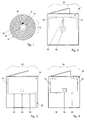
- Fig. 1 shows a rotational data carrier 10 with a detection wafer 12 of a chip 14 and a chip 14 connected to the central coupling loop 16.
- the chip 14 with the coupling loop 16 is located on a plastic film 18 which is glued to the uncoated center 20 of the data carrier 10.
- the coupling loop 16 per se forms a small magnetic antenna for the magnetic components of an electromagnetic field and is only slightly influenced by surrounding conductive components, namely a metallic coating 22 of the data carrier 10 in their radiation properties.
- the coupling loop 16 can therefore be coupled in the near field directly to a magnetic reading antenna or coupled via a low-impedance coupling region of a passive amplifier antenna with this amplifier antenna and read in the far field with a magnetic or electrical reading antenna.
- Fig. 2 shows a data carrier sleeve 24 with a designed as a repeater antenna dipole antenna 26 from a central loop 28, feed and fitting areas 30 and angled radiators 32.
- the coupling loop 16 of the Detektierplättchens 12 is coupled to the central loop 28 of the dipole antenna 26 and the central loop 28 in turn over the parallel and planar to the coating 22 of the data carrier 10 extending, parts of the dipole antenna 26 which act as feed and adaptation regions 30 are connected to the actual radiators 32 of the dipole antenna 26.
- These radiators 32 extend at the edge of the data carrier sleeve 24 and bend symmetrically at the corners, where they in turn expire at the edge of the data carrier sleeve 24.
- the dipole antenna 26 can receive or radiate the electrical components of an electromagnetic field.
- Fig. 3 shows a data carrier sleeve 24 with a first variant of the dipole antenna 26. This consists of a straight offset to the center coupling region 34, dining and fitting areas 30 and oppositely arranged radiators 32nd
- Fig. 4 shows a data carrier sleeve 24 with a second variant of the dipole antenna 26. This also consists of a center offset to the coupling region 34, dining and fitting areas 30 but in the same direction arranged radiators 32.
- the radiator 32 extend at the in Fig. 4 shown left and right side of the disk cover 24 first up, kink At the upper corners at a right angle and still extend partially along the top of the disk cover 24. For electrical extension, the ends of the radiator 32 are configured meandering.
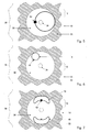
- Fig. 5 1 shows a rotary data carrier 10 with a detector wafer 12 comprising a chip 14 and an eccentric coupling loop 16 enclosing a spindle hole 36.
- An amplifier antenna coupled to the coupling loop 16 is represented here by a slot antenna 38 which is connected through the coating 22 of the data carrier 10 in conjunction with the microwave circular uncoated center 20 of the data carrier 10 itself is formed.
- the circular uncoated center 20 of the data carrier 10 represents an expanded slot whose low-impedance region is coupled to the coupling loop 16 of the detector wafer 12.
- Fig. 6 1 shows a rotation data carrier 10 with a detection wafer 12 made of a chip 14 and a first variant of the eccentric coupling loop 16.
- the Köppelschleife 16 with a circular shape is arranged here outside a spindle hole 36.
- Fig. 7 1 shows a rotation data carrier 10 with a detection wafer 12 made of a chip 14 and a second variant of the eccentric coupling loop 16.
- the coupling loop 16 is likewise arranged outside a spindle hole 36, but has a kidney-shaped shape which is adapted to the inner circumference of the coating 22.
- the coupling loop 16 is associated with a similarly shaped counterweight 40, which is arranged mirror-symmetrically to a plane passing through the axis of rotation mirror axis.
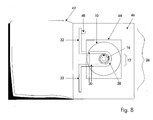
- Fig. 8 shows a data carrier 42 formed as a book 42 with a pocket 44 with a dipole antenna 26 from a central loop 28, feed and fitting areas 30 and emitters 32.
- the dipole antenna 26 is located on or in the bag 44 carrying the cover page or the book cover 46.
- the cover page or the book cover 46 may be equipped with its own detector plate 48, which is coupled to the same dipole antenna 26. By using a conventional anti-collision method, both detector plates 12; 48 are read independently.
- the inventive design enables the following applications in commerce, libraries and archives.
- inventories of the data medium inventory can be made without having to remove the data carriers from the envelope, from packaging or shelves.
- Adjacent data carriers whose detection plates are in the same reading field can be distinguished by a conventional anti-collision method.
- Data carriers with small read range detection plates can be increased in conjunction with envelopes or packaging in the reading range.
- the reading range can be significantly increased without material overhead compared to the read range of the pure detector wafer. Hidden or lying data carriers can be detected.
- the removal of data carriers can be registered and then monitored by evaluating the far field of further transport. This allows you to determine whether a disk is then properly registered in the cashier or lending area and checked out or stolen. Even manipulations by wrapping a data carrier in a shielding material can be revealed by a gap in the read contact to a disk is determined by gapless large-scale monitoring, without this was properly checked out in the cashier or lending area after registration.
Landscapes
- Engineering & Computer Science (AREA)
- Computer Security & Cryptography (AREA)
- Computer Hardware Design (AREA)
- Theoretical Computer Science (AREA)
- Software Systems (AREA)
- Physics & Mathematics (AREA)
- General Engineering & Computer Science (AREA)
- General Physics & Mathematics (AREA)
- Variable-Direction Aerials And Aerial Arrays (AREA)
- Optical Record Carriers And Manufacture Thereof (AREA)
- Measuring Magnetic Variables (AREA)
Applications Claiming Priority (1)
| Application Number | Priority Date | Filing Date | Title |
|---|---|---|---|
| DE102007026984A DE102007026984A1 (de) | 2007-06-07 | 2007-06-07 | Rotationsdatenträger mit Detektierplättchen |
Publications (2)
| Publication Number | Publication Date |
|---|---|
| EP2000960A2 true EP2000960A2 (fr) | 2008-12-10 |
| EP2000960A3 EP2000960A3 (fr) | 2009-09-09 |
Family
ID=39650489
Family Applications (1)
| Application Number | Title | Priority Date | Filing Date |
|---|---|---|---|
| EP08010246A Withdrawn EP2000960A3 (fr) | 2007-06-07 | 2008-06-05 | Support de données de rotation doté de petites plaques de détection |
Country Status (3)
| Country | Link |
|---|---|
| US (1) | US20080307449A1 (fr) |
| EP (1) | EP2000960A3 (fr) |
| DE (1) | DE102007026984A1 (fr) |
Cited By (1)
| Publication number | Priority date | Publication date | Assignee | Title |
|---|---|---|---|---|
| WO2010029218A1 (fr) * | 2008-09-10 | 2010-03-18 | Upm Raflatac Oy | Boîtier |
Families Citing this family (4)
| Publication number | Priority date | Publication date | Assignee | Title |
|---|---|---|---|---|
| EP2296149A1 (fr) * | 2009-05-27 | 2011-03-16 | Nxp B.V. | Appareil de stockage de supports numériques comprenant un système d'identification par radiofréquence |
| TWI478438B (zh) * | 2011-04-21 | 2015-03-21 | China Steel Corp | 具有平面式圓極化天線之無線識別標籤 |
| JP5587356B2 (ja) * | 2012-02-24 | 2014-09-10 | 富士フイルム株式会社 | 放射線撮影システム、放射線撮影システムの駆動制御方法および駆動制御プログラム、並びに放射線画像検出装置 |
| CN116075827A (zh) * | 2020-09-08 | 2023-05-05 | 尖能株式会社 | 带rfid标签的安装部件、带rfid标签的安装部件的制造方法、带rfid标签的安装部件的头部及rfid标签装配单元 |
Family Cites Families (19)
| Publication number | Priority date | Publication date | Assignee | Title |
|---|---|---|---|---|
| WO2000023994A1 (fr) * | 1998-10-16 | 2000-04-27 | Intermec Ip Corp. | Supports optiques intelligents |
| JP2000132871A (ja) * | 1998-10-22 | 2000-05-12 | Hitachi Ltd | ディスク及びこれを用いた記録再生装置 |
| DE19920449A1 (de) * | 1999-05-04 | 2000-11-09 | Silver Reader Inc | Optisches Aufzeichnungsmedium mit einem Speicherchip |
| DE10004429C1 (de) * | 2000-02-02 | 2001-05-31 | Skidata Ag | Verfahren zur Herstellung eines Gegenstandes mit einem Transponder |
| DE10032604A1 (de) * | 2000-07-07 | 2002-01-17 | Turhan Guenaydin | Kopierschutzvorrichtung für Datenträger |
| EP1553576A4 (fr) * | 2002-08-09 | 2010-11-10 | Panasonic Corp | Disque optique et dispositif de commande a distance |
| US20040052202A1 (en) * | 2002-09-13 | 2004-03-18 | Brollier Brian W. | RFID enabled information disks |
| US7443299B2 (en) * | 2003-04-25 | 2008-10-28 | Avery Dennison Corporation | Extended range RFID system |
| WO2004099821A1 (fr) * | 2003-05-07 | 2004-11-18 | Kenetics Innovations Pte Ltd | Procede et appareil permettant d'ameliorer les performances d'une etiquette d'identification par radiofrequence conçue pour un disque compact |
| ATE414976T1 (de) * | 2004-05-17 | 2008-12-15 | Sony Dadc Austria Ag | Optischer datenträger, verfahren und vorrichtung zur herstellung eines optischen datenträgers |
| DE102004031879B4 (de) * | 2004-06-30 | 2017-11-02 | Ovd Kinegram Ag | Sicherheitsdokument zur RF-Identifikation |
| US7292147B2 (en) * | 2004-09-24 | 2007-11-06 | Microsoft Corporation | Optical disk and method of integrating a high gain RFID antenna |
| US7378971B2 (en) * | 2004-10-01 | 2008-05-27 | Hitachi America, Ltd. | Radio frequency identification tags for digital storage discs |
| US7688206B2 (en) * | 2004-11-22 | 2010-03-30 | Alien Technology Corporation | Radio frequency identification (RFID) tag for an item having a conductive layer included or attached |
| US20070040653A1 (en) * | 2005-08-16 | 2007-02-22 | Potts Kevin L | Rfid shielding devices |
| GB2430583B (en) * | 2005-09-27 | 2007-10-03 | Tag Company | Security and identification tags |
| JP4811055B2 (ja) * | 2006-02-28 | 2011-11-09 | ソニー株式会社 | 非対称平面アンテナ、その製造方法及び信号処理ユニット |
| JP4560017B2 (ja) * | 2006-08-03 | 2010-10-13 | 株式会社日立製作所 | ディスクメディアおよびディスクメディアの製造方法 |
| US7886315B2 (en) * | 2007-01-30 | 2011-02-08 | Sony Corporation | Optical disc case, optical disc tray, card member, and manufacturing method |
-
2007
- 2007-06-07 DE DE102007026984A patent/DE102007026984A1/de not_active Ceased
-
2008
- 2008-06-05 EP EP08010246A patent/EP2000960A3/fr not_active Withdrawn
- 2008-06-06 US US12/157,101 patent/US20080307449A1/en not_active Abandoned
Cited By (1)
| Publication number | Priority date | Publication date | Assignee | Title |
|---|---|---|---|---|
| WO2010029218A1 (fr) * | 2008-09-10 | 2010-03-18 | Upm Raflatac Oy | Boîtier |
Also Published As
| Publication number | Publication date |
|---|---|
| DE102007026984A1 (de) | 2008-12-11 |
| EP2000960A3 (fr) | 2009-09-09 |
| US20080307449A1 (en) | 2008-12-11 |
Similar Documents
| Publication | Publication Date | Title |
|---|---|---|
| DE602004009430T2 (de) | Antennenstruktur für Funketikett für optisches Aufzeichnungsmedium | |
| US7268687B2 (en) | Radio frequency identification tags with compensating elements | |
| DE60317185T2 (de) | Drahtloses kommunikationsgerät und verfahren | |
| DE69811740T2 (de) | Identifikationsetikett mit verbesserter sicherheit | |
| DE602004004216T2 (de) | Rahmenantennenvorrichtung | |
| EP2009583B1 (fr) | Support de données sur carte doté de petites plaques de détection | |
| EP1102207B1 (fr) | Dispositif d'étiquette | |
| KR101700696B1 (ko) | 하이브리드 안테나 rfid 엘리먼트를 지향시키기 위한 구조를 갖는 조합 eas 및 rfid 보안 태그 | |
| EP1910872B1 (fr) | Étiquette rfid contenant deux circuits réglés | |
| EP1791610B1 (fr) | Systeme pour identifier et compter des puces de jeu | |
| EP2000960A2 (fr) | Support de données de rotation doté de petites plaques de détection | |
| US20210117751A1 (en) | Rfid tag with integrated antenna | |
| EP1711914B1 (fr) | Etiquette de resonance a fixer sur un support de donnees muni d'une metallisation | |
| DE102004031118A1 (de) | Schein, Lese-Vorrichtung und Schein-Identifikations-System | |
| EP2168081B1 (fr) | Dispositif, procédé et utilisation permettant le blindage d'un transpondeur rfid contre les champs magnétiques | |
| DE19538917C2 (de) | Kontaktlose Chipkarte | |
| EP3649581B1 (fr) | Dispositif et procédé de sécurisation d'un produit | |
| DE102013109212B4 (de) | RFID-Vorrichtung, RFID-Lesegerät, Portionsheißgetränkmaschine und System | |
| JP4275063B2 (ja) | 同一性を識別する安全ラベルを有する対象物 | |
| DE102013022310A1 (de) | RFID-Lesegerät | |
| HK1103372B (en) | System for gaming chip identification and counting |
Legal Events
| Date | Code | Title | Description |
|---|---|---|---|
| PUAI | Public reference made under article 153(3) epc to a published international application that has entered the european phase |
Free format text: ORIGINAL CODE: 0009012 |
|
| AK | Designated contracting states |
Kind code of ref document: A2 Designated state(s): AT BE BG CH CY CZ DE DK EE ES FI FR GB GR HR HU IE IS IT LI LT LU LV MC MT NL NO PL PT RO SE SI SK TR |
|
| AX | Request for extension of the european patent |
Extension state: AL BA MK RS |
|
| PUAL | Search report despatched |
Free format text: ORIGINAL CODE: 0009013 |
|
| AK | Designated contracting states |
Kind code of ref document: A3 Designated state(s): AT BE BG CH CY CZ DE DK EE ES FI FR GB GR HR HU IE IS IT LI LT LU LV MC MT NL NO PL PT RO SE SI SK TR |
|
| AX | Request for extension of the european patent |
Extension state: AL BA MK RS |
|
| RIC1 | Information provided on ipc code assigned before grant |
Ipc: G11B 7/24 20060101ALI20090806BHEP Ipc: G11B 23/00 20060101ALI20090806BHEP Ipc: G11B 20/00 20060101ALI20090806BHEP Ipc: G06F 21/00 20060101ALI20090806BHEP Ipc: E05B 73/00 20060101ALI20090806BHEP Ipc: H01Q 1/22 20060101ALI20090806BHEP Ipc: H01Q 9/04 20060101ALI20090806BHEP Ipc: H01Q 1/38 20060101ALI20090806BHEP Ipc: G06K 19/077 20060101AFI20080807BHEP |
|
| AKX | Designation fees paid | ||
| STAA | Information on the status of an ep patent application or granted ep patent |
Free format text: STATUS: THE APPLICATION IS DEEMED TO BE WITHDRAWN |
|
| 18D | Application deemed to be withdrawn |
Effective date: 20100310 |
|
| REG | Reference to a national code |
Ref country code: DE Ref legal event code: 8566 |