EP2000960A2 - Rotating data carrier with detection pad - Google Patents
Rotating data carrier with detection pad Download PDFInfo
- Publication number
- EP2000960A2 EP2000960A2 EP08010246A EP08010246A EP2000960A2 EP 2000960 A2 EP2000960 A2 EP 2000960A2 EP 08010246 A EP08010246 A EP 08010246A EP 08010246 A EP08010246 A EP 08010246A EP 2000960 A2 EP2000960 A2 EP 2000960A2
- Authority
- EP
- European Patent Office
- Prior art keywords
- data carrier
- detector plate
- antenna
- coupling loop
- dipole antenna
- Prior art date
- Legal status (The legal status is an assumption and is not a legal conclusion. Google has not performed a legal analysis and makes no representation as to the accuracy of the status listed.)
- Withdrawn
Links
Images
Classifications
-
- G—PHYSICS
- G06—COMPUTING OR CALCULATING; COUNTING
- G06F—ELECTRIC DIGITAL DATA PROCESSING
- G06F21/00—Security arrangements for protecting computers, components thereof, programs or data against unauthorised activity
- G06F21/70—Protecting specific internal or peripheral components, in which the protection of a component leads to protection of the entire computer
- G06F21/78—Protecting specific internal or peripheral components, in which the protection of a component leads to protection of the entire computer to assure secure storage of data
- G06F21/80—Protecting specific internal or peripheral components, in which the protection of a component leads to protection of the entire computer to assure secure storage of data in storage media based on magnetic or optical technology, e.g. disks with sectors
-
- G—PHYSICS
- G11—INFORMATION STORAGE
- G11B—INFORMATION STORAGE BASED ON RELATIVE MOVEMENT BETWEEN RECORD CARRIER AND TRANSDUCER
- G11B23/00—Record carriers not specific to the method of recording or reproducing; Accessories, e.g. containers, specially adapted for co-operation with the recording or reproducing apparatus ; Intermediate mediums; Apparatus or processes specially adapted for their manufacture
- G11B23/0014—Record carriers not specific to the method of recording or reproducing; Accessories, e.g. containers, specially adapted for co-operation with the recording or reproducing apparatus ; Intermediate mediums; Apparatus or processes specially adapted for their manufacture record carriers not specifically of filamentary or web form
- G11B23/0021—Record carriers not specific to the method of recording or reproducing; Accessories, e.g. containers, specially adapted for co-operation with the recording or reproducing apparatus ; Intermediate mediums; Apparatus or processes specially adapted for their manufacture record carriers not specifically of filamentary or web form discs
- G11B23/0028—Details
- G11B23/0035—Details means incorporated in the disc, e.g. hub, to enable its guiding, loading or driving
- G11B23/0042—Details means incorporated in the disc, e.g. hub, to enable its guiding, loading or driving with provision for auxiliary features
-
- G—PHYSICS
- G11—INFORMATION STORAGE
- G11B—INFORMATION STORAGE BASED ON RELATIVE MOVEMENT BETWEEN RECORD CARRIER AND TRANSDUCER
- G11B23/00—Record carriers not specific to the method of recording or reproducing; Accessories, e.g. containers, specially adapted for co-operation with the recording or reproducing apparatus ; Intermediate mediums; Apparatus or processes specially adapted for their manufacture
- G11B23/28—Indicating or preventing prior or unauthorised use, e.g. cassettes with sealing or locking means, write-protect devices for discs
- G11B23/286—Antitheft arrangements, e.g. Electronic Article Surveillance [EAS] tags
-
- G—PHYSICS
- G11—INFORMATION STORAGE
- G11B—INFORMATION STORAGE BASED ON RELATIVE MOVEMENT BETWEEN RECORD CARRIER AND TRANSDUCER
- G11B33/00—Constructional parts, details or accessories not provided for in the other groups of this subclass
- G11B33/02—Cabinets; Cases; Stands; Disposition of apparatus therein or thereon
- G11B33/04—Cabinets; Cases; Stands; Disposition of apparatus therein or thereon modified to store record carriers
- G11B33/0405—Cabinets; Cases; Stands; Disposition of apparatus therein or thereon modified to store record carriers for storing discs
- G11B33/0411—Single disc boxes
-
- G—PHYSICS
- G11—INFORMATION STORAGE
- G11B—INFORMATION STORAGE BASED ON RELATIVE MOVEMENT BETWEEN RECORD CARRIER AND TRANSDUCER
- G11B33/00—Constructional parts, details or accessories not provided for in the other groups of this subclass
- G11B33/02—Cabinets; Cases; Stands; Disposition of apparatus therein or thereon
- G11B33/04—Cabinets; Cases; Stands; Disposition of apparatus therein or thereon modified to store record carriers
- G11B33/0405—Cabinets; Cases; Stands; Disposition of apparatus therein or thereon modified to store record carriers for storing discs
- G11B33/0433—Multiple disc containers
-
- H—ELECTRICITY
- H01—ELECTRIC ELEMENTS
- H01Q—ANTENNAS, i.e. RADIO AERIALS
- H01Q1/00—Details of, or arrangements associated with, antennas
- H01Q1/12—Supports; Mounting means
- H01Q1/22—Supports; Mounting means by structural association with other equipment or articles
- H01Q1/2208—Supports; Mounting means by structural association with other equipment or articles associated with components used in interrogation type services, i.e. in systems for information exchange between an interrogator/reader and a tag/transponder, e.g. in Radio Frequency Identification [RFID] systems
- H01Q1/2225—Supports; Mounting means by structural association with other equipment or articles associated with components used in interrogation type services, i.e. in systems for information exchange between an interrogator/reader and a tag/transponder, e.g. in Radio Frequency Identification [RFID] systems used in active tags, i.e. provided with its own power source or in passive tags, i.e. deriving power from RF signal
-
- G—PHYSICS
- G06—COMPUTING OR CALCULATING; COUNTING
- G06F—ELECTRIC DIGITAL DATA PROCESSING
- G06F2221/00—Indexing scheme relating to security arrangements for protecting computers, components thereof, programs or data against unauthorised activity
- G06F2221/21—Indexing scheme relating to G06F21/00 and subgroups addressing additional information or applications relating to security arrangements for protecting computers, components thereof, programs or data against unauthorised activity
- G06F2221/2101—Auditing as a secondary aspect
-
- G—PHYSICS
- G06—COMPUTING OR CALCULATING; COUNTING
- G06F—ELECTRIC DIGITAL DATA PROCESSING
- G06F2221/00—Indexing scheme relating to security arrangements for protecting computers, components thereof, programs or data against unauthorised activity
- G06F2221/21—Indexing scheme relating to G06F21/00 and subgroups addressing additional information or applications relating to security arrangements for protecting computers, components thereof, programs or data against unauthorised activity
- G06F2221/2121—Chip on media, e.g. a disk or tape with a chip embedded in its case
Definitions
- the invention relates to a rotary data carrier with a detector wafer according to the preamble of claim 1.
- Rotational media with a metallic coating is known as CDs, DVDs, Blue-Ray DVDs, and HD DVDs. They serve u. a. for storing copyright-protected works, such as computer programs, data collections, literature, art, image, music and cinematographic works, some of considerable value.
- the invention has for its object to provide in radio-based detection plates on a rotary disk with a metallic coating, the prerequisites for, if necessary, increasing the reading range.
- the invention is based on the consideration that predominate by an inductive coupling loop, the magnetic components of the alternating electromagnetic field in the near field and therefore the propagation of the electromagnetic alternating field by metallic objects, in the present case, the metallic coating of the data carrier is less affected in the near field, as in use an antenna preferably radiating the electrical components.
- the detector plate may be arranged on a plastic film which is glued to the data carrier.
- any rotational data carrier can be equipped according to the invention without intervention in its production process and without impairment of the usual use.
- the coupling loop of the detector wafer may be coupled to an amplifier antenna.
- the reading range of the detector plate can be significantly increased.
- the amplifier antenna can be designed as a dipole antenna.
- a precise adaptation of the resonant frequency of the antenna to the operating frequency of the detector wafer and reading device can be made in a simple manner via its design, in particular its length and shape, so that the antenna can radiate with the maximum possible efficiency.
- the dipole antenna is preferably arranged in a casing or packaging of the data carrier.
- a distance of the radiator of the dipole antenna from the coating of the data carrier can be achieved, which reduces a detuning of the dipole antenna and thus a sufficient reading range of the Detektierplättchens allows. Furthermore, optionally a small reading range of the detector wafer without casing or packaging and a high reading range of the detector wafer with casing or packaging is made possible.
- the dipole antenna is not visible on a back side of a printed inlay of the case, on the back of the holder of the data carrier in the case or on an antenna carrier inserted between the holder of the data carrier and the printed inlay of the case.
- the dipole antenna is also optically hidden, so that it is not apparent without opening the case, whether the disk is equipped with the shell with the invention or not ,
- the dipole antenna consists of a coupling region extending in the center or near the center of the envelope or packaging and radiators running along the edges of the envelope or packaging.
- the parallel to the coating of the data carrier extending portions of the dipole antenna act predominantly as a feed line and electrical extension of the radiator and extending along the edges of the envelope or package emitters
- the tuned to the resonant frequency radiating elements of the dipole antenna are
- the amplifier antenna may be formed as a slot antenna, wherein the slot is formed by the central uncoated area of the data carrier itself.
- a slot antenna is characterized by a narrow slot in an electrically conductive environment, the length of the slot corresponding to one or more times a quarter wavelength of the resonant frequency of the slot antenna.
- the electrically conductive environment is formed by the metallic coating of the data carrier itself and the slot is widened to the circular, uncoated center of the data carrier.
- the coupling loop of the detector plate is preferably arranged asymmetrically to the axis of rotation of the data carrier.
- the coupling loop of the detector wafer can enclose a spindle hole of the data carrier.
- This embodiment has the advantage that distance tolerances between the coupling loop and the edge of the coating of the data carrier uncritically affect the degree of coupling between the coupling loop and the slot antenna and the center of mass of the data carrier is largely maintained.
- the coupling loop of the detector wafer may also be arranged outside a spindle hole of the data carrier.
- the optimum of the impedance matching between the coupling loop of the detector wafer and that of the slot antenna can be calculated and set very precisely.
- the coupling loop of the detector wafer may be circular or oval in shape or have a shape that allows optimum matching to the chip and the slot antenna on the given surface.
- the coupling loop of the detector plate can be kidney-shaped and adapted to the inner circle of the coating.
- the coupling loop of the detector plate may be opposed to a preferably similarly shaped counterweight mirror-symmetrically to a plane passing through the axis of rotation mirror axis.
- the counterweight could also be designed as an additional detector plate, which uses the same slot antenna.
- the dipole antenna arranged in the envelope or packaging of the data carrier can be coupled to the coupling loop of the detector wafer arranged asymmetrically with respect to the axis of rotation of the data carrier.
- the dipole antenna disposed in the case or package of the data carrier may be coupled to the slot antenna of the data carrier.
- the slot antenna acts as a mediator or parasitic element between the coupling loop on the data carrier and the coupling region of the dipole antenna.
- the dipole antenna arranged in the envelope or packaging of the data carrier can also be coupled both with the coupling loop of the detector wafer arranged asymmetrically to the axis of rotation of the data carrier and with the slot antenna of the data carrier.
- the advantages of a large read range are linked by direct coupling with the coupling loop with the advantages of coupling independent of the orientation of the data carrier in the envelope or package.
- At least two separate coupling loops could be connected even with a chip having a plurality of terminals, of which one centric and the other is arranged eccentrically on the disk.
- the centric coupling loop then allows rotational position independent coupling with the dipole antenna and the eccentric coupling loop coupling with the slot antenna.
- a data carrier with the described Detektierplättchen regardless of whether the coupling loop is symmetrical to the center of the disk, so concentric, or asymmetric to the center of the disk, that is eccentric, and regardless of whether an amplifier antenna is coupled to the coupling loop, the disk has through the coupling loop of the detector wafer always a stand-alone magnetic antenna that can be read in the near field with a magnetic reading antenna.
- Nearby electrically conductive objects cause only a slight, practically negligible attenuation.
- a reading contact with a magnetic reading antenna in the near field is ensured under practical conditions.
- the associated low reading range has the advantage that influences of adjacent data carriers are low and readers either manage without anti-collision methods, or if using an anti-collision method, only minor collisions have to be taken into account and only a short time is required for a secure reading process.
- a data carrier in which the slot antenna formed by the data carrier itself serves as an amplifier antenna can be additionally read in the far field with a magnetic or electrical reading antenna.
- the read range of the data carrier designed in this way ie without any material overhead and without data carrier wrap or packaging, was able to detect approximately half of the maximum read range that otherwise could only be achieved with a separate amplifier antenna designed as a dipole antenna in a casing or packaging of the data carrier , By this reading variant thus manipulation attempts can be revealed, in which a disk is removed from the case in the assumption, thereby the readability in the far field can be eliminated.
- a data carrier with the described Detektierplättchen regardless of whether the coupling loop is symmetrical to the center of the disk, so concentric, or asymmetric to the center of the disk, that is arranged eccentrically and is coupled in a shell or packaging with a formed as a separate dipole antenna amplifier antenna, reached the maximum reading range in the far field, as can be achieved with standard detection plates.
- These Read range was largely independent of whether the dipole antenna served exclusively or in combination with the slot antenna as the amplifier antenna and whether the slot antenna acted as an additional coupler between the coupling loop and the slot antenna.
- the figures of the read range are only measured values an experimental set-up.
- an increase in the read transmission power and the receiver sensitivity higher reading ranges are also possible.
- the data carrier sleeve can be designed as a book with a pocket, be arranged in or on a cover page or a book cover coupled to the coupling loop of the detection wafer of the data carrier dipole antenna and be arranged in or on the cover page or the cover another detection wafer, which is coupled to the same dipole antenna.
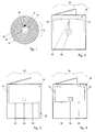
- Fig. 1 shows a rotational data carrier 10 with a detection wafer 12 of a chip 14 and a chip 14 connected to the central coupling loop 16.
- the chip 14 with the coupling loop 16 is located on a plastic film 18 which is glued to the uncoated center 20 of the data carrier 10.
- the coupling loop 16 per se forms a small magnetic antenna for the magnetic components of an electromagnetic field and is only slightly influenced by surrounding conductive components, namely a metallic coating 22 of the data carrier 10 in their radiation properties.
- the coupling loop 16 can therefore be coupled in the near field directly to a magnetic reading antenna or coupled via a low-impedance coupling region of a passive amplifier antenna with this amplifier antenna and read in the far field with a magnetic or electrical reading antenna.
- Fig. 2 shows a data carrier sleeve 24 with a designed as a repeater antenna dipole antenna 26 from a central loop 28, feed and fitting areas 30 and angled radiators 32.
- the coupling loop 16 of the Detektierplättchens 12 is coupled to the central loop 28 of the dipole antenna 26 and the central loop 28 in turn over the parallel and planar to the coating 22 of the data carrier 10 extending, parts of the dipole antenna 26 which act as feed and adaptation regions 30 are connected to the actual radiators 32 of the dipole antenna 26.
- These radiators 32 extend at the edge of the data carrier sleeve 24 and bend symmetrically at the corners, where they in turn expire at the edge of the data carrier sleeve 24.
- the dipole antenna 26 can receive or radiate the electrical components of an electromagnetic field.
- Fig. 3 shows a data carrier sleeve 24 with a first variant of the dipole antenna 26. This consists of a straight offset to the center coupling region 34, dining and fitting areas 30 and oppositely arranged radiators 32nd
- Fig. 4 shows a data carrier sleeve 24 with a second variant of the dipole antenna 26. This also consists of a center offset to the coupling region 34, dining and fitting areas 30 but in the same direction arranged radiators 32.
- the radiator 32 extend at the in Fig. 4 shown left and right side of the disk cover 24 first up, kink At the upper corners at a right angle and still extend partially along the top of the disk cover 24. For electrical extension, the ends of the radiator 32 are configured meandering.
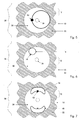
- Fig. 5 1 shows a rotary data carrier 10 with a detector wafer 12 comprising a chip 14 and an eccentric coupling loop 16 enclosing a spindle hole 36.
- An amplifier antenna coupled to the coupling loop 16 is represented here by a slot antenna 38 which is connected through the coating 22 of the data carrier 10 in conjunction with the microwave circular uncoated center 20 of the data carrier 10 itself is formed.
- the circular uncoated center 20 of the data carrier 10 represents an expanded slot whose low-impedance region is coupled to the coupling loop 16 of the detector wafer 12.
- Fig. 6 1 shows a rotation data carrier 10 with a detection wafer 12 made of a chip 14 and a first variant of the eccentric coupling loop 16.
- the Köppelschleife 16 with a circular shape is arranged here outside a spindle hole 36.
- Fig. 7 1 shows a rotation data carrier 10 with a detection wafer 12 made of a chip 14 and a second variant of the eccentric coupling loop 16.
- the coupling loop 16 is likewise arranged outside a spindle hole 36, but has a kidney-shaped shape which is adapted to the inner circumference of the coating 22.
- the coupling loop 16 is associated with a similarly shaped counterweight 40, which is arranged mirror-symmetrically to a plane passing through the axis of rotation mirror axis.
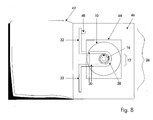
- Fig. 8 shows a data carrier 42 formed as a book 42 with a pocket 44 with a dipole antenna 26 from a central loop 28, feed and fitting areas 30 and emitters 32.
- the dipole antenna 26 is located on or in the bag 44 carrying the cover page or the book cover 46.
- the cover page or the book cover 46 may be equipped with its own detector plate 48, which is coupled to the same dipole antenna 26. By using a conventional anti-collision method, both detector plates 12; 48 are read independently.
- the inventive design enables the following applications in commerce, libraries and archives.
- inventories of the data medium inventory can be made without having to remove the data carriers from the envelope, from packaging or shelves.
- Adjacent data carriers whose detection plates are in the same reading field can be distinguished by a conventional anti-collision method.
- Data carriers with small read range detection plates can be increased in conjunction with envelopes or packaging in the reading range.
- the reading range can be significantly increased without material overhead compared to the read range of the pure detector wafer. Hidden or lying data carriers can be detected.
- the removal of data carriers can be registered and then monitored by evaluating the far field of further transport. This allows you to determine whether a disk is then properly registered in the cashier or lending area and checked out or stolen. Even manipulations by wrapping a data carrier in a shielding material can be revealed by a gap in the read contact to a disk is determined by gapless large-scale monitoring, without this was properly checked out in the cashier or lending area after registration.
Landscapes
- Engineering & Computer Science (AREA)
- Computer Security & Cryptography (AREA)
- Computer Hardware Design (AREA)
- Theoretical Computer Science (AREA)
- Software Systems (AREA)
- Physics & Mathematics (AREA)
- General Engineering & Computer Science (AREA)
- General Physics & Mathematics (AREA)
- Variable-Direction Aerials And Aerial Arrays (AREA)
- Optical Record Carriers And Manufacture Thereof (AREA)
- Measuring Magnetic Variables (AREA)
Abstract
Es wird ein Rotationsdatenträger (10) mit Detektierplättchen (12) beschrieben. Das Detektierplättchen (12) besteht aus einem Chip (14) und einer mit dem Chip verbundenen magnetischen Koppelschleife (16), das auf dem zentralen, nicht beschichteten Bereich (20) des Datenträgers (10) angeordnet ist.A rotary data carrier (10) with detector plates (12) is described. The detector wafer (12) consists of a chip (14) and a magnetic coupling loop (16) connected to the chip, which is arranged on the central, uncoated region (20) of the data carrier (10).
Description
Die Erfindung betrifft einen Rotationsdatenträger mit einem Detektierplättchen nach dem Oberbegriff des Anspruchs 1.The invention relates to a rotary data carrier with a detector wafer according to the preamble of
Rotationsdatenträger mit einer metallischen Beschichtung sind als CDs, DVDs, Blue-Ray-DVDs und HD-DVDs bekannt. Sie dienen u. a. zur Speicherung urhebergeschützter Werke, wie Computerprogramme, Datensammlungen, Literatur-, Kunst-, Bild-, Musik-und Filmwerke mit teilweise erheblichem Wert.Rotational media with a metallic coating is known as CDs, DVDs, Blue-Ray DVDs, and HD DVDs. They serve u. a. for storing copyright-protected works, such as computer programs, data collections, literature, art, image, music and cinematographic works, some of considerable value.
Um Verluste von Einzelhandelsunternehmen und Leihstellen zu begrenzen oder die Registrierung verkaufter oder verliehener Waren zu erleichtern, ist es an sich bekannt, Waren mit Sicherungsetiketten zu versehen, die im Kassen- oder Verleihbereich nach Entrichtung des Kauf- oder Verleihpreises deaktiviert werden und/oder maschinell lesbare Inventaretiketten zu verwenden, die die maschinelle Registrierung verkaufter oder verliehener Waren ermöglichen.In order to limit losses of retailers and rental agencies or to facilitate the registration of goods sold or lent, it is known per se to provide goods with security tags that are deactivated in cash or rental area after payment of the purchase or rental price and / or machine readable To use inventory labels that allow for the automated registration of goods sold or lent.
Derzeit sind optisch lesbare Barcodes zur Registrierung im Kassen- oder Verleihbereich und Ein-Bit-Erfassungssysteme als Diebstahlssicherung im Ausgangsbereich Standard. Darüber hinaus werden auch zunehmend Funksyteme verwendet, die eine Registrierung oder Diebstahlssicherung über eine größere Distanz auch dann ermöglichen, wenn kein optischer Sichtkontakt zwischen dem Detektierplättchen an der Ware und einem Lesegerät besteht. Vorraussetzung für eine ausreichende Reichweite ist hierbei allerdings eine weitgehend ungedämpfte Umgebung des funkgestützten Detektierplättchens an der Ware.Currently, optically readable bar codes for cash desk or rental registration and single-bit acquisition systems are standard in the exit area for theft protection. In addition, radio systems are increasingly being used which enable registration or theft protection over a greater distance even when there is no visual visual contact between the detector wafer on the goods and a reading device. A prerequisite for a sufficient range, however, is a largely undamped environment of the radio-based detector wafer on the goods.
Wegen der als Metallisierung für optische Sensoren ausgeführten Beschichtung von Rotationsdatenträgern, die gleichzeitig elektrisch leitfähig ist, ergeben sich allerdings Reichweitenprobleme beim Einsatz von funkgestützten Detektierplättchen auf dem Datenträger.Because of the designed as metallization for optical sensors coating of rotary data carriers, which is simultaneously electrically conductive, however, range problems arise when using radio-based detection plates on the disk.
Der Erfindung liegt die Aufgabe zugrunde, bei funkgestützten Detektierplättchen auf einem Rotationsdatenträger mit einer metallischen Beschichtung die Vorraussetzungen für eine bedarfsweise Erhöhung der Lesereichweite zu schaffen.The invention has for its object to provide in radio-based detection plates on a rotary disk with a metallic coating, the prerequisites for, if necessary, increasing the reading range.
Diese Aufgabe wird bei einem Rotationsdatenträger mit einem Detektierplättchen nach dem Oberbegriff des Anspruchs 1 durch die Merkmale dieses Anspruchs 1 gelöst.This object is achieved in a rotary disk with a detection wafer according to the preamble of
Weiterbildungen und vorteilhafte Ausgestaltungen ergeben sich aus den Unteransprüchen.Further developments and advantageous embodiments will become apparent from the dependent claims.
Der Erfindung liegt die Überlegung zugrunde, dass durch eine induktive Koppelschleife die magnetischen Komponenten des elektromagnetischen Wechselfeldes im Nahfeld überwiegen und daher die Ausbreitung des elektromagnetischen Wechselfeldes durch metallische Gegenstände, im vorliegenden Fall die metallische Beschichtung des Datenträgers, im Nahfeld weniger beeinträchtigt wird, als bei Verwendung einer die elektrischen Komponenten bevorzugt abstrahlenden Antenne.The invention is based on the consideration that predominate by an inductive coupling loop, the magnetic components of the alternating electromagnetic field in the near field and therefore the propagation of the electromagnetic alternating field by metallic objects, in the present case, the metallic coating of the data carrier is less affected in the near field, as in use an antenna preferably radiating the electrical components.
Das Detektierplättchen kann auf einer Kunststofffolie angeordnet sein, die mit dem Datenträger verklebt ist.The detector plate may be arranged on a plastic film which is glued to the data carrier.
Dadurch kann jeder beliebige Rotationsdatenträger ohne Eingriff in dessen Herstellungsprozess und ohne Beeinträchtigung der üblichen Nutzung erfindungsgemäß ausgestattet werden.As a result, any rotational data carrier can be equipped according to the invention without intervention in its production process and without impairment of the usual use.
Die Koppelschleife des Detektierplättchens kann mit einer Verstärkerantenne gekoppelt sein.The coupling loop of the detector wafer may be coupled to an amplifier antenna.
Über die Kopplung mit einer Verstärkerantenne, die eine rein passiv wirkende Komponente bildet, kann die Lesereichweite des Detektierplättchens wesentlich erhöht werden.By coupling with an amplifier antenna, which forms a purely passive-acting component, the reading range of the detector plate can be significantly increased.
Die Verstärkerantenne kann als Dipolantenne ausgebildet sein.The amplifier antenna can be designed as a dipole antenna.
Durch eine Dipolantenne kann über deren Design, insbesondere deren Länge und Form, in einfacher Weise eine exakte Anpassung der Resonanzfrequenz der Antenne an die Arbeitsfrequenz des Detektierplättchens und Lesegeräts vorgenommen werden, so dass die Antenne mit dem maximal möglichen Wirkungsgrad strahlen kann.By means of a dipole antenna, a precise adaptation of the resonant frequency of the antenna to the operating frequency of the detector wafer and reading device can be made in a simple manner via its design, in particular its length and shape, so that the antenna can radiate with the maximum possible efficiency.
Die Dipolantenne ist vorzugsweise in einer Hülle oder Verpackung des Datenträgers angeordnet.The dipole antenna is preferably arranged in a casing or packaging of the data carrier.
Durch die Gestaltung der Hülle oder Verpackung kann ein Abstand der Strahler der Dipolantenne von der Beschichtung des Datenträgers erreicht werden, der eine Verstimmung der Dipolantenne reduziert und so eine hinreichende Lesereichweite des Detektierplättchens ermöglicht. Weiterhin wird wahlweise eine geringe Lesereichweite des Detektierplättchens ohne Hülle oder Verpackung und eine hohe Lesereichweite des Detektierplättchens mit Hülle oder Verpackung ermöglicht.Due to the design of the envelope or packaging, a distance of the radiator of the dipole antenna from the coating of the data carrier can be achieved, which reduces a detuning of the dipole antenna and thus a sufficient reading range of the Detektierplättchens allows. Furthermore, optionally a small reading range of the detector wafer without casing or packaging and a high reading range of the detector wafer with casing or packaging is made possible.
Vorzugsweise befindet sich die Dipolantenne nicht sichbar auf einer Rückseite eines bedruckten Inlays der Hülle, auf der Rückseite der Halterung des Datenträgers in der Hülle oder auf einem zwischen der Halterung des Datenträgers und dem bedruckten Inlay der Hülle eingelegten Antennenträger.Preferably, the dipole antenna is not visible on a back side of a printed inlay of the case, on the back of the holder of the data carrier in the case or on an antenna carrier inserted between the holder of the data carrier and the printed inlay of the case.
Neben einem mechanischen Abstand von der Beschichtung des Datenträgers, der eine Reduzierung der Verstimmung durch Beschichtung bewirkt, wird die Dipolantenne auch optisch verborgen angeordnet, so dass ohne Öffnung der Hülle nicht erkennbar ist, ob der Datenträger mit der Hülle mit der Erfindung ausgestattet ist oder nicht.In addition to a mechanical distance from the coating of the data carrier, which causes a reduction of detuning by coating, the dipole antenna is also optically hidden, so that it is not apparent without opening the case, whether the disk is equipped with the shell with the invention or not ,
Bei einer bevorzugten Ausgestaltung besteht die Dipolantenne aus einem im Zentrum oder nahe des Zentrums der Hülle oder Verpackung verlaufenden Koppelbereich und längs der Kanten der Hülle oder Verpackung verlaufenden Strahlern.In a preferred embodiment, the dipole antenna consists of a coupling region extending in the center or near the center of the envelope or packaging and radiators running along the edges of the envelope or packaging.
So erfolgt im Koppelbereich der Dipolantenne eine Stromkopplung zwischen der Koppelschleife des Detektierplättchens und dem niederohmigen Bereich der Dipolantenne, die parallel zur Beschichtung des Datenträgers verlaufenden Bereiche der Dipolantenne wirken überwiegend als Speiseleitung und elektrische Verlängerung der Strahler und die längs der Kanten der Hülle oder Verpackung verlaufenden Strahler stellen schließlich die auf die Resonanzfrequenz abgestimmten strahlenden Elemente der Dipolantenne dar.Thus, in the coupling region of the dipole antenna current coupling takes place between the coupling loop of the detector wafer and the low-impedance region of the dipole antenna, the parallel to the coating of the data carrier extending portions of the dipole antenna act predominantly as a feed line and electrical extension of the radiator and extending along the edges of the envelope or package emitters Finally, the tuned to the resonant frequency radiating elements of the dipole antenna.
Alternativ kann die Verstärkerantenne als Schlitzantenne ausgebildet sein, wobei der Schlitz durch den zentrischen unbeschichteten Bereich des Datenträgers selbst gebildet ist.Alternatively, the amplifier antenna may be formed as a slot antenna, wherein the slot is formed by the central uncoated area of the data carrier itself.
An sich ist eine Schlitzantenne durch einen schmalen Schlitz in einer elektrisch leitfähigen Umgebung charakterisiert, wobei die Länge des Schlitzes einem Ein- oder Mehrfachen einer Viertelwellenlänge der Resonanzfrequenz der Schlitzantenne entspricht. Im vorliegenden Fall ist die elektrisch leitfähige Umgebung durch die metallische Beschichtung des Datenträgers selbst gebildet und der Schlitz ist zu dem kreisförmigen, nicht beschichteten Zentrum des Datenträgers aufgeweitet.As such, a slot antenna is characterized by a narrow slot in an electrically conductive environment, the length of the slot corresponding to one or more times a quarter wavelength of the resonant frequency of the slot antenna. In the present case, the electrically conductive environment is formed by the metallic coating of the data carrier itself and the slot is widened to the circular, uncoated center of the data carrier.
Dieses von der Norm des Datenträgers vorgegebene Design legt zwangsläufig die beeinflussbaren Grenzen der Resonanzfrequenz der durch die Beschichtung des Datenträgers gebildeten Schlitzantenne fest. Allerdings ist durch die Form des Schlitzes als kreisförmiges unbeschichtetes Zentrum bereits eine erhöhte Breitbandigkeit der Schlitzantenne gegenüber einem schmalen, länglichen Schlitz gegeben. Darüber hinaus lässt sich die Resonanzfrequenz der Schlitzantenne auch durch das Design und den Koppelgrad der Koppelschleife in Grenzen beeinflussen.This predetermined by the standard of the disk design inevitably sets the modifiable limits of the resonant frequency of the slot antenna formed by the coating of the disk. However, due to the shape of the slot as a circular uncoated center, an increased bandwidth of the slot antenna compared to a narrow, elongated slot already exists. In addition, the resonant frequency of the slot antenna can also be limited by the design and the degree of coupling of the coupling loop.
Versuche und Berechnungen haben gezeigt, dass trotz einer verbleibenden Fehlanpassung im Frequenzbereich zwischen 800 und 1000 MHz eine Lesereichweite erzielt werden kann, die zumindest der Hälfte der Lesereichweite einer Kopplung mit einer vorbeschriebenen Dipolantenne entspricht, und deutlich höher liegt, als die Lesereichweite der Koppelschleife für sich genommen.Experiments and calculations have shown that despite a remaining mismatch in the frequency range between 800 and 1000 MHz, a reading range corresponding to at least half the reading range of a coupling with a dipole antenna described above, and significantly higher than the read range of the coupling loop per se taken.
Die Koppelschleife des Detektierplättchens ist vorzugsweise asymmetrisch zur Rotationsachse des Datenträgers angeordnet.The coupling loop of the detector plate is preferably arranged asymmetrically to the axis of rotation of the data carrier.
Dadurch wird eine verbesserte Impedanzanpassung zwischen der Koppelschleife und der Schlitzantenne erzielt.This achieves improved impedance matching between the coupling loop and the slot antenna.
Die Koppelschleife des Detektierplättchens kann ein Spindelloch des Datenträgers umschließen.The coupling loop of the detector wafer can enclose a spindle hole of the data carrier.
Diese Ausführung hat den Vorteil, dass sich Abstandtoleranzen zwischen der Koppelschleife und dem Rand der Beschichtung des Datenträges unkritisch auf den Kopplungsgrad zwischen der Koppelschleife und der Schlitzantenne auswirken und der Massenschwerpunkt des Datenträgers weitgehend erhalten bleibt.This embodiment has the advantage that distance tolerances between the coupling loop and the edge of the coating of the data carrier uncritically affect the degree of coupling between the coupling loop and the slot antenna and the center of mass of the data carrier is largely maintained.
Die Koppelschleife des Detektierplättchens kann auch außerhalb eines Spindellochs des Datenträgers angeordnet sein.The coupling loop of the detector wafer may also be arranged outside a spindle hole of the data carrier.
Dadurch lässt sich dass Optimum der Impedanzanpassung zwischen der Koppelschleife des Detektierplättchens und der der Schlitzantenne sehr genau berechnen und einstellen.As a result, the optimum of the impedance matching between the coupling loop of the detector wafer and that of the slot antenna can be calculated and set very precisely.
Die Koppelschleife des Detektierplättchens kann kreisförmig oder oval geformt sein oder eine Form haben, die auf der gegebenen Fläche eine optimale Anpassung an den Chip und die Schlitzantenne erlaubt.The coupling loop of the detector wafer may be circular or oval in shape or have a shape that allows optimum matching to the chip and the slot antenna on the given surface.
Dies ermöglicht eine Vereinfachung der Berechnung der Impedanzanpassung zwischen der Koppelschleife und der Schlitzantenne und damit vorhersehbare reproduzierbare Ergebnisse bei der praktischen Umsetzung.This allows a simplification of the calculation of the impedance matching between the coupling loop and the slot antenna and thus predictable reproducible results in the practical implementation.
Die Koppelschleife des Detektierplättchens kann nierenförmig geformt und dem Innenkreis der Beschichtung angepasst sein.The coupling loop of the detector plate can be kidney-shaped and adapted to the inner circle of the coating.
Hierdurch lässt sich sowohl ein besonders starker Koppelgrad erzielen und gleichzeitig die Resonanzfrequenz der Schlitzantenne beeinflussen.This makes it possible to achieve both a particularly strong degree of coupling and at the same time influence the resonant frequency of the slot antenna.
Der Koppelschleife des Detektierplättchens kann ein vorzugsweise gleichartig geformtes Gegengewicht spiegelsymmetrisch zu einer durch die Rotationsachse verlaufende Spiegelachse gegenübergestellt sein.The coupling loop of the detector plate may be opposed to a preferably similarly shaped counterweight mirror-symmetrically to a plane passing through the axis of rotation mirror axis.
Es ist dadurch möglich, Verlagerungen des Massenschwerpunktes des Datenträgers, hervorgerufen durch die asymmetrische Anordnung des Detektierplättchen zu kompensieren. Weiterhin könnte das Gegengewicht auch als zusätzliches Detektierplättchen ausgebildet sein, das die gleiche Schlitzantenne nutzt.It is thereby possible to compensate for displacements of the center of mass of the data carrier, caused by the asymmetrical arrangement of the detector plate. Furthermore, the counterweight could also be designed as an additional detector plate, which uses the same slot antenna.
Die in der Hülle oder Verpackung des Datenträgers angeordnete Dipolantenne kann mit der asymmetrisch zur Rotationsachse des Datenträgers angeordneten Koppelschleife des Detektierplättchens gekoppelt sein.The dipole antenna arranged in the envelope or packaging of the data carrier can be coupled to the coupling loop of the detector wafer arranged asymmetrically with respect to the axis of rotation of the data carrier.
Ein und dieselbe asymmetrisch zur Rotationsachse des Datenträgers angeordnete Koppelschleife, die ohne Hülle oder Verpackung zur Kopplung mit der Schlitzantenne dient, wird hier zusätzlich zur Kopplung mit der Dipolantenne genutzt, wenn der Datenträger sich in der Hülle oder Verpackung befindet. Allerdings ist der Kopplungsgrad und damit die Lesereichweite von der Drehausrichtung des Datenträgers in der Hülle oder Verpackung und damit der asymmetrisch, also exzentrisch angeordneten Koppelschleife auf dem Datenträger abhängig.One and the same asymmetrically arranged to the axis of rotation of the data carrier coupling loop, which serves without a sleeve or packaging for coupling with the slot antenna is used here in addition to the coupling with the dipole antenna, when the disk is in the case or packaging. However, the degree of coupling and thus the reading range of the Drehausrichtung the disk in the case or packaging and thus the asymmetric, so eccentrically arranged coupling loop on the disk dependent.
Die in der Hülle oder Verpackung des Datenträgers angeordnete Dipolantenne kann mit der Schlitzantenne des Datenträgers gekoppelt sein.The dipole antenna disposed in the case or package of the data carrier may be coupled to the slot antenna of the data carrier.
Bei dieser Ausführung wirkt die Schlitzantenne als Mittler oder parasitäres Element zwischen der Koppelschleife auf dem Datenträger und dem Koppelbereich der Dipolantenne. Der Vorteil dieser Ausführung besteht darin, dass die Lesereichweite von der Ausrichtung des Datenträgers in der Hülle oder Verpackung unabhängig ist.In this embodiment, the slot antenna acts as a mediator or parasitic element between the coupling loop on the data carrier and the coupling region of the dipole antenna. The advantage this embodiment is that the reading range is independent of the orientation of the data carrier in the case or packaging.
Die in der Hülle oder Verpackung des Datenträgers angeordnete Dipolantenne kann auch sowohl mit der asymmetrisch zur Rotationsachse des Datenträgers angeordneten Koppelschleife des Detektierplättchens als auch mit der Schlitzantenne des Datenträgers gekoppelt sein.The dipole antenna arranged in the envelope or packaging of the data carrier can also be coupled both with the coupling loop of the detector wafer arranged asymmetrically to the axis of rotation of the data carrier and with the slot antenna of the data carrier.
Bei dieser Ausführung werden die Vorteile einer großen Lesereichweite durch direkte Kopplung mit der Koppelschleife mit den Vorteilen einer von der Ausrichtung des Datenträgers in der Hülle oder Verpackung unabhängigen Kopplung verknüpft.In this embodiment, the advantages of a large read range are linked by direct coupling with the coupling loop with the advantages of coupling independent of the orientation of the data carrier in the envelope or package.
Alternativ könnten auch bei einem Chip mit mehreren Anschlüssen wenigstens zwei getrennte Koppelschleifen angeschlossen werden, von denen eine zentrisch und die andere exzentrisch auf dem Datenträger angeordnet ist. Die zentrische Koppelschleife ermöglicht dann eine drehpositionsunabhängige Kopplung mit der Dipolantenne und die exzentrische Koppelschleife eine Kopplung mit der Schlitzantenne.Alternatively, at least two separate coupling loops could be connected even with a chip having a plurality of terminals, of which one centric and the other is arranged eccentrically on the disk. The centric coupling loop then allows rotational position independent coupling with the dipole antenna and the eccentric coupling loop coupling with the slot antenna.
Es ergeben sich so eine Vielzahl von Kombinationsmöglichkeiten der verschiedenen Antennen und damit Lesereichweiten. Ein Datenträger mit dem beschriebenen Detektierplättchen, unabhängig davon, ob die Koppelschleife symmetrisch zum Zentrum des Datenträgers, also konzentrisch, oder asymmetrisch zum Zentrum des Datenträgers, also exzentrisch angeordnet ist, und unabhängig davon, ob eine Verstärkerantenne mit der Koppelschleife gekoppelt ist, besitzt der Datenträger durch die Koppelschleife des Detektierplättchens stets eine eigenständige magnetische Antenne, die im Nahfeld mit einer magnetischen Leseantenne gelesen werden kann. In der Nähe befindliche elektrisch leitfähige Gegenstände bewirken nur eine geringfügige, praktisch vernachlässigbare Dämpfung. Somit ist ein Lesekontakt mit einer magnetischen Lesantenne im Nahfeld unter praktischen Bedingungen gewährleistet. Die hiermit verknüpfte geringe Lesereichweite hat den Vorteil, dass Einflüsse benachbarter Datenträger gering sind und Lesegeräte entweder ohne Antikollisionsverfahren auskommen, oder bei Anwendung eines Antikollisionsverfahren nur wenig Kollisionen berücksichtigen müssen und für einen sicheren Lesevorgang nur eine kurze Zeit benötigt wird.This results in a variety of possible combinations of different antennas and thus reading ranges. A data carrier with the described Detektierplättchen, regardless of whether the coupling loop is symmetrical to the center of the disk, so concentric, or asymmetric to the center of the disk, that is eccentric, and regardless of whether an amplifier antenna is coupled to the coupling loop, the disk has through the coupling loop of the detector wafer always a stand-alone magnetic antenna that can be read in the near field with a magnetic reading antenna. Nearby electrically conductive objects cause only a slight, practically negligible attenuation. Thus, a reading contact with a magnetic reading antenna in the near field is ensured under practical conditions. The associated low reading range has the advantage that influences of adjacent data carriers are low and readers either manage without anti-collision methods, or if using an anti-collision method, only minor collisions have to be taken into account and only a short time is required for a secure reading process.
Ein Datenträger, bei dem die durch den Datenträger selbst gebildete Schlitzantenne als Verstärkerantenne dient, kann im Fernfeld zusätzlich mit einer magnetischen oder elektrischen Leseantenne gelesen werden. Als Lesereichweite des so ausgestalteten Datenträgers, also ohne jeglichen materiellen Mehraufwand und ohne Datenträgerhülle oder Verpackung konnte hier etwa die Hälfte der maximalen Lesereichweite nachgewiesen werden, wie sie sonst nur mit einer separaten, als Dipolantenne ausgebildeten Verstärkerantenne in einer Hülle oder Verpackung des Datenträgers erzielt werden konnte. Durch diese Lesevariante können somit Manipulationsversuche aufgedeckt werden, bei denen ein Datenträger aus der Hülle entfernt wird in der Annahme, dadurch könne die Lesbarkeit im Fernfeld beseitigt werden.A data carrier in which the slot antenna formed by the data carrier itself serves as an amplifier antenna can be additionally read in the far field with a magnetic or electrical reading antenna. The read range of the data carrier designed in this way, ie without any material overhead and without data carrier wrap or packaging, was able to detect approximately half of the maximum read range that otherwise could only be achieved with a separate amplifier antenna designed as a dipole antenna in a casing or packaging of the data carrier , By this reading variant thus manipulation attempts can be revealed, in which a disk is removed from the case in the assumption, thereby the readability in the far field can be eliminated.
Ein Datenträger mit dem beschriebenen Detektierplättchen, unabhängig davon, ob die Koppelschleife symmetrisch zum Zentrum des Datenträgers, also konzentrisch, oder asymmetrisch zum Zentrum des Datenträgers, also exzentrisch angeordnet ist und der in einer Hülle oder Verpackung mit einer als separate Dipolantenne ausgebildeten Verstärkerantenne gekoppelt ist, erreichte im Fernfeld die maximale Lesereichweite, wie sie auch mit Standarddetektierplättchen erreicht werden kann. Diese Lesereichreichweite war weitgehend unabhängig davon, ob die Dipolantenne ausschließlich oder in Kombination mit der Schlitzantenne als Verstärkerantenne diente und ob die Schlitzantenne als zusätzlicher Koppler zwischen der Koppelschleife und der Schlitzantenne wirkte.A data carrier with the described Detektierplättchen, regardless of whether the coupling loop is symmetrical to the center of the disk, so concentric, or asymmetric to the center of the disk, that is arranged eccentrically and is coupled in a shell or packaging with a formed as a separate dipole antenna amplifier antenna, reached the maximum reading range in the far field, as can be achieved with standard detection plates. These Read range was largely independent of whether the dipole antenna served exclusively or in combination with the slot antenna as the amplifier antenna and whether the slot antenna acted as an additional coupler between the coupling loop and the slot antenna.
Im Übrigen sind die Zahlenangaben der Lesereichweite lediglich Messwerte eine Versuchsanordnung. Durch Einsatz von Leserichtantennen, einer Erhöhung der Lesesendeleistung und der Empfängerempfindlichkeit sind auch höhere Lesereichweiten möglich.Incidentally, the figures of the read range are only measured values an experimental set-up. Through the use of read-only antennas, an increase in the read transmission power and the receiver sensitivity, higher reading ranges are also possible.
In einer weiteren Ausführung kann die Datenträgerhülle als Buch mit einer Tasche ausgebildet sein, in oder auf einer Einbandseite oder einem Buchdeckel eine mit der Koppelschleife des Detektierplättchens des Datenträgers gekoppelte Dipolantenne angeordnet sein und in oder auf der Einbandseite oder dem Buchdeckel ein weiteres Detektierplättchen angeordnet sein, das mit derselben Dipolantenne gekoppelt ist.In a further embodiment, the data carrier sleeve can be designed as a book with a pocket, be arranged in or on a cover page or a book cover coupled to the coupling loop of the detection wafer of the data carrier dipole antenna and be arranged in or on the cover page or the cover another detection wafer, which is coupled to the same dipole antenna.
Nachfolgend wird die Erfindung anhand von Ausführungsbeispielen erläutert, die in der Zeichnung dargestellt sind. In der Zeichnung zeigen:
- Fig. 1
- einen Rotationsdatenträger mit einem Detektierplättchen aus einem Chip und einer zentrischen Koppelschleife,
- Fig. 2
- eine Datenträgerhülle mit einer Dipolantenne aus einer zentralen Schleife, Speise- und Anpassbereichen und abgewinkelten Strahlern,
- Fig. 3
- eine Datenträgerhülle mit einer Dipolantenne aus einem Koppelbereich, Speiseund Anpassbereichen und gegensinnig angeordneten Strahlern,
- Fig. 4
- eine Datenträgerhülle mit einer Dipolantenne aus einem Koppelbereich, Speiseund Anpassbereichen und gleichsinnig angeordneten Strahlern,
- Fig. 5
- einen Rotationsdatenträger mit einem Detektierplättchen aus einem Chip und einer exzentrischen, ein Spindelloch umschließenden Koppelschleife,
- Fig. 6
- einen Rotationsdatenträger mit einem Detektierplättchen aus einem Chip und einer exzentrischen, außerhalb eines Spindellochs angeordneten Koppelschleife,
- Fig. 7
- einen Rotationsdatenträger mit einem Detektierplättchen aus einem Chip und einer exzentrischen, außerhalb eines Spindellochs angeordneten Koppelschleife in nierenförmiger Gestalt und einem Gegengewicht und
- Fig. 8
- eine als Buch mit einer Tasche ausgebildete Datenträgerhülle mit einer Dipolantenne aus einer zentralen Schleife, Speise- und Anpassbereichen und Strahlern,
- Fig. 1
- a rotation data carrier with a detection wafer consisting of a chip and a centric coupling loop,
- Fig. 2
- a data carrier sleeve with a dipole antenna from a central loop, feed and fitting areas and angled spotlights,
- Fig. 3
- a data carrier shell with a dipole antenna from a coupling area, dining and fitting areas and radiators arranged in opposite directions,
- Fig. 4
- a data carrier casing with a dipole antenna from a coupling region, food and adaptation regions and emitters arranged in the same direction,
- Fig. 5
- a rotary data carrier with a detector chip of a chip and a eccentric, a spindle hole enclosing coupling loop,
- Fig. 6
- a rotation data carrier with a detection wafer made of a chip and an eccentric coupling loop arranged outside a spindle hole,
- Fig. 7
- a rotary data carrier with a detector wafer of a chip and an eccentric, arranged outside a spindle hole coupling loop in kidney-shaped and a counterweight and
- Fig. 8
- a volume cover designed as a book with a pocket with a dipole antenna of a central loop, dining and fitting areas and spotlights,
Im Randbereich der Datenträgerhülle 24 besteht ein ausreichender Abstand zur Beschichtung 22, so dass die Dipolantenne 26 hier die elektrischen Komponenten eines elektromagnetischen Feldes empfangen oder abstrahlen kann.In the edge region of the
Die erfindungsgemäße Ausgestaltung ermöglicht folgende Anwendungen im Handel, in Bibliotheken und Archiven.The inventive design enables the following applications in commerce, libraries and archives.
Aufgrund der großen Lesereichweite können Inventuren des Datenträgerbestandes vorgenommen werden, ohne dass dazu die Datenträger aus der Hülle, aus Verpackungen oder Regalen entnommen werden müssen. Benachbarte Datenträger, deren Detektierplättchen sich im selben Lesefeld befinden, können durch ein übliches Antikollisionsverfahren unterschieden werden.Due to the large reading range, inventories of the data medium inventory can be made without having to remove the data carriers from the envelope, from packaging or shelves. Adjacent data carriers whose detection plates are in the same reading field can be distinguished by a conventional anti-collision method.
Trotz kleinerer Bauformen im Vergleich zu Büchern lässt sich auch bei reinen Datenträgern oder in Hüllen aufbewahrten Datenträgern eine ähnlich hohe Lesereichweite erzielen.Despite smaller designs compared to books, a similarly high reading range can be achieved even with pure data carriers or data carriers stored in cases.
Datenträger mit Detektierplättchen kleiner Lesereichweite können in Verbindung mit Hüllen oder Verpackungen in der Lesereichweite erhöht werden.Data carriers with small read range detection plates can be increased in conjunction with envelopes or packaging in the reading range.
Bei Nutzung des Datenträgers als Schlitzantenne kann die Lesereichweite ohne materiellen Mehraufwand gegenüber der Lesereichweite des reinen Detektierplättchens deutlich erhöht werden. Verdeckte oder herumliegende Datenträger können aufgespürt werden.When using the data carrier as a slot antenna, the reading range can be significantly increased without material overhead compared to the read range of the pure detector wafer. Hidden or lying data carriers can be detected.
Durch begrenzte Auswertung des Nahfeldes innerhalb eines Regals kann die Entnahme von Datenträgern registriert und anschließend durch Auswertung des Fernfeldes der weitere Transport überwacht werden. So lässt sich feststellen, ob ein Datenträger anschließend ordnungsgemäß im Kassen- oder Ausleihbereich registriert und ausgecheckt wird oder entwendet werden soll. Selbst Manipulationen durch Einwickeln eines Datenträgers in abschirmendes Material können aufgedeckt werden, indem durch lückenlose großräumige Überwachung eine Unterbrechung des Lesekontakts zu einem Datenträger festgestellt wird, ohne dass dieser ordnungsgemäß im Kassen- oder Ausleihbereich nach Registrierung ausgecheckt wurde.By limited evaluation of the near field within a shelf, the removal of data carriers can be registered and then monitored by evaluating the far field of further transport. This allows you to determine whether a disk is then properly registered in the cashier or lending area and checked out or stolen. Even manipulations by wrapping a data carrier in a shielding material can be revealed by a gap in the read contact to a disk is determined by gapless large-scale monitoring, without this was properly checked out in the cashier or lending area after registration.
Claims (18)
Applications Claiming Priority (1)
| Application Number | Priority Date | Filing Date | Title |
|---|---|---|---|
| DE102007026984A DE102007026984A1 (en) | 2007-06-07 | 2007-06-07 | Rotational data carrier with detector plates |
Publications (2)
| Publication Number | Publication Date |
|---|---|
| EP2000960A2 true EP2000960A2 (en) | 2008-12-10 |
| EP2000960A3 EP2000960A3 (en) | 2009-09-09 |
Family
ID=39650489
Family Applications (1)
| Application Number | Title | Priority Date | Filing Date |
|---|---|---|---|
| EP08010246A Withdrawn EP2000960A3 (en) | 2007-06-07 | 2008-06-05 | Rotating data carrier with detection pad |
Country Status (3)
| Country | Link |
|---|---|
| US (1) | US20080307449A1 (en) |
| EP (1) | EP2000960A3 (en) |
| DE (1) | DE102007026984A1 (en) |
Cited By (1)
| Publication number | Priority date | Publication date | Assignee | Title |
|---|---|---|---|---|
| WO2010029218A1 (en) * | 2008-09-10 | 2010-03-18 | Upm Raflatac Oy | Casing |
Families Citing this family (4)
| Publication number | Priority date | Publication date | Assignee | Title |
|---|---|---|---|---|
| EP2296149A1 (en) * | 2009-05-27 | 2011-03-16 | Nxp B.V. | Apparatus for storing digital media that includes a radio frequency identification system |
| TWI478438B (en) * | 2011-04-21 | 2015-03-21 | China Steel Corp | Wireless identification tag having circular polarization planar antenna |
| JP5587356B2 (en) * | 2012-02-24 | 2014-09-10 | 富士フイルム株式会社 | Radiation imaging system, radiation imaging system drive control method, drive control program, and radiation image detection apparatus |
| CN116075827A (en) * | 2020-09-08 | 2023-05-05 | 尖能株式会社 | Mounting part with RFID tag, manufacturing method of mounting part with RFID tag, head of mounting part with RFID tag, and RFID tag mounting unit |
Family Cites Families (19)
| Publication number | Priority date | Publication date | Assignee | Title |
|---|---|---|---|---|
| WO2000023994A1 (en) * | 1998-10-16 | 2000-04-27 | Intermec Ip Corp. | Smart optical storage media |
| JP2000132871A (en) * | 1998-10-22 | 2000-05-12 | Hitachi Ltd | Disc and recording / reproducing apparatus using the same |
| DE19920449A1 (en) * | 1999-05-04 | 2000-11-09 | Silver Reader Inc | Optical recording medium structure with a memory chip for use in a compact disc-read only memory, compact disc, video compact disc, digital video disc or others |
| DE10004429C1 (en) * | 2000-02-02 | 2001-05-31 | Skidata Ag | Manufacturing method for object provided with data transponder e.g. CD or DVD, has carrier foil supporting semiconductor chip and antenna coil applied to object surface and subsequently dissolved |
| DE10032604A1 (en) * | 2000-07-07 | 2002-01-17 | Turhan Guenaydin | Copy-protection device for data carriers e.g. digital music cassettes, CDs, DVDs, has coding applied to data carrier for reading by sensor |
| EP1553576A4 (en) * | 2002-08-09 | 2010-11-10 | Panasonic Corp | OPTICAL DISK AND REMOTE CONTROL DEVICE |
| US20040052202A1 (en) * | 2002-09-13 | 2004-03-18 | Brollier Brian W. | RFID enabled information disks |
| US7443299B2 (en) * | 2003-04-25 | 2008-10-28 | Avery Dennison Corporation | Extended range RFID system |
| WO2004099821A1 (en) * | 2003-05-07 | 2004-11-18 | Kenetics Innovations Pte Ltd | A method and apparatus for enhancing performance of an rfid tag for a compact disc |
| ATE414976T1 (en) * | 2004-05-17 | 2008-12-15 | Sony Dadc Austria Ag | OPTICAL DATA CARRIER, METHOD AND DEVICE FOR PRODUCING AN OPTICAL DATA CARRIER |
| DE102004031879B4 (en) * | 2004-06-30 | 2017-11-02 | Ovd Kinegram Ag | Security document for RF identification |
| US7292147B2 (en) * | 2004-09-24 | 2007-11-06 | Microsoft Corporation | Optical disk and method of integrating a high gain RFID antenna |
| US7378971B2 (en) * | 2004-10-01 | 2008-05-27 | Hitachi America, Ltd. | Radio frequency identification tags for digital storage discs |
| US7688206B2 (en) * | 2004-11-22 | 2010-03-30 | Alien Technology Corporation | Radio frequency identification (RFID) tag for an item having a conductive layer included or attached |
| US20070040653A1 (en) * | 2005-08-16 | 2007-02-22 | Potts Kevin L | Rfid shielding devices |
| GB2430583B (en) * | 2005-09-27 | 2007-10-03 | Tag Company | Security and identification tags |
| JP4811055B2 (en) * | 2006-02-28 | 2011-11-09 | ソニー株式会社 | Asymmetric planar antenna, method for manufacturing the same, and signal processing unit |
| JP4560017B2 (en) * | 2006-08-03 | 2010-10-13 | 株式会社日立製作所 | Disc media and method for producing disc media |
| US7886315B2 (en) * | 2007-01-30 | 2011-02-08 | Sony Corporation | Optical disc case, optical disc tray, card member, and manufacturing method |
-
2007
- 2007-06-07 DE DE102007026984A patent/DE102007026984A1/en not_active Ceased
-
2008
- 2008-06-05 EP EP08010246A patent/EP2000960A3/en not_active Withdrawn
- 2008-06-06 US US12/157,101 patent/US20080307449A1/en not_active Abandoned
Cited By (1)
| Publication number | Priority date | Publication date | Assignee | Title |
|---|---|---|---|---|
| WO2010029218A1 (en) * | 2008-09-10 | 2010-03-18 | Upm Raflatac Oy | Casing |
Also Published As
| Publication number | Publication date |
|---|---|
| DE102007026984A1 (en) | 2008-12-11 |
| EP2000960A3 (en) | 2009-09-09 |
| US20080307449A1 (en) | 2008-12-11 |
Similar Documents
| Publication | Publication Date | Title |
|---|---|---|
| DE602004009430T2 (en) | Antenna structure for radio tag for optical recording medium | |
| US7268687B2 (en) | Radio frequency identification tags with compensating elements | |
| DE60317185T2 (en) | WIRELESS COMMUNICATION DEVICE AND METHOD | |
| DE69811740T2 (en) | IDENTIFICATION LABEL WITH IMPROVED SECURITY | |
| DE602004004216T2 (en) | Loop antenna device | |
| EP2009583B1 (en) | Card data carrier with detection pad | |
| EP1102207B1 (en) | Label device | |
| KR101700696B1 (en) | Combination eas and rfid security tag having structure for orienting a hybrid antenna rfid element | |
| EP1910872B1 (en) | Rfid tag containing two tuned circuits | |
| EP1791610B1 (en) | System for gaming chip identification and counting | |
| EP2000960A2 (en) | Rotating data carrier with detection pad | |
| US20210117751A1 (en) | Rfid tag with integrated antenna | |
| EP1711914B1 (en) | Resonant label for applying to a data carrier that is provided with a metallisation | |
| DE102004031118A1 (en) | Bill, reader and bill ID system | |
| EP2168081B1 (en) | Apparatus, method and use for screening the magnetic field of an rfid transponder | |
| DE19538917C2 (en) | Contactless chip card | |
| EP3649581B1 (en) | Device and method for preventing counterfeiting of a product | |
| DE102013109212B4 (en) | RFID device, RFID reader, portion hot drink machine and system | |
| JP4275063B2 (en) | Objects with safety labels that identify identity | |
| DE102013022310A1 (en) | RFID reader | |
| HK1103372B (en) | System for gaming chip identification and counting |
Legal Events
| Date | Code | Title | Description |
|---|---|---|---|
| PUAI | Public reference made under article 153(3) epc to a published international application that has entered the european phase |
Free format text: ORIGINAL CODE: 0009012 |
|
| AK | Designated contracting states |
Kind code of ref document: A2 Designated state(s): AT BE BG CH CY CZ DE DK EE ES FI FR GB GR HR HU IE IS IT LI LT LU LV MC MT NL NO PL PT RO SE SI SK TR |
|
| AX | Request for extension of the european patent |
Extension state: AL BA MK RS |
|
| PUAL | Search report despatched |
Free format text: ORIGINAL CODE: 0009013 |
|
| AK | Designated contracting states |
Kind code of ref document: A3 Designated state(s): AT BE BG CH CY CZ DE DK EE ES FI FR GB GR HR HU IE IS IT LI LT LU LV MC MT NL NO PL PT RO SE SI SK TR |
|
| AX | Request for extension of the european patent |
Extension state: AL BA MK RS |
|
| RIC1 | Information provided on ipc code assigned before grant |
Ipc: G11B 7/24 20060101ALI20090806BHEP Ipc: G11B 23/00 20060101ALI20090806BHEP Ipc: G11B 20/00 20060101ALI20090806BHEP Ipc: G06F 21/00 20060101ALI20090806BHEP Ipc: E05B 73/00 20060101ALI20090806BHEP Ipc: H01Q 1/22 20060101ALI20090806BHEP Ipc: H01Q 9/04 20060101ALI20090806BHEP Ipc: H01Q 1/38 20060101ALI20090806BHEP Ipc: G06K 19/077 20060101AFI20080807BHEP |
|
| AKX | Designation fees paid | ||
| STAA | Information on the status of an ep patent application or granted ep patent |
Free format text: STATUS: THE APPLICATION IS DEEMED TO BE WITHDRAWN |
|
| 18D | Application deemed to be withdrawn |
Effective date: 20100310 |
|
| REG | Reference to a national code |
Ref country code: DE Ref legal event code: 8566 |