EP2000807A1 - Reaktionsverfahren in einem mikrochip-kanal und analysegerät - Google Patents
Reaktionsverfahren in einem mikrochip-kanal und analysegerät Download PDFInfo
- Publication number
- EP2000807A1 EP2000807A1 EP07714663A EP07714663A EP2000807A1 EP 2000807 A1 EP2000807 A1 EP 2000807A1 EP 07714663 A EP07714663 A EP 07714663A EP 07714663 A EP07714663 A EP 07714663A EP 2000807 A1 EP2000807 A1 EP 2000807A1
- Authority
- EP
- European Patent Office
- Prior art keywords
- flow channel
- reagent
- reaction
- wall surface
- gas
- Prior art date
- Legal status (The legal status is an assumption and is not a legal conclusion. Google has not performed a legal analysis and makes no representation as to the accuracy of the status listed.)
- Granted
Links
Images


Classifications
-
- G—PHYSICS
- G01—MEASURING; TESTING
- G01N—INVESTIGATING OR ANALYSING MATERIALS BY DETERMINING THEIR CHEMICAL OR PHYSICAL PROPERTIES
- G01N35/00—Automatic analysis not limited to methods or materials provided for in any single one of groups G01N1/00 - G01N33/00; Handling materials therefor
- G01N35/10—Devices for transferring samples or any liquids to, in, or from, the analysis apparatus, e.g. suction devices, injection devices
- G01N35/1095—Devices for transferring samples or any liquids to, in, or from, the analysis apparatus, e.g. suction devices, injection devices for supplying the samples to flow-through analysers
-
- B—PERFORMING OPERATIONS; TRANSPORTING
- B01—PHYSICAL OR CHEMICAL PROCESSES OR APPARATUS IN GENERAL
- B01L—CHEMICAL OR PHYSICAL LABORATORY APPARATUS FOR GENERAL USE
- B01L3/00—Containers or dishes for laboratory use, e.g. laboratory glassware; Droppers
- B01L3/50—Containers for the purpose of retaining a material to be analysed, e.g. test tubes
- B01L3/502—Containers for the purpose of retaining a material to be analysed, e.g. test tubes with fluid transport, e.g. in multi-compartment structures
- B01L3/5027—Containers for the purpose of retaining a material to be analysed, e.g. test tubes with fluid transport, e.g. in multi-compartment structures by integrated microfluidic structures, i.e. dimensions of channels and chambers are such that surface tension forces are important, e.g. lab-on-a-chip
- B01L3/502738—Containers for the purpose of retaining a material to be analysed, e.g. test tubes with fluid transport, e.g. in multi-compartment structures by integrated microfluidic structures, i.e. dimensions of channels and chambers are such that surface tension forces are important, e.g. lab-on-a-chip characterised by integrated valves
-
- B—PERFORMING OPERATIONS; TRANSPORTING
- B01—PHYSICAL OR CHEMICAL PROCESSES OR APPARATUS IN GENERAL
- B01L—CHEMICAL OR PHYSICAL LABORATORY APPARATUS FOR GENERAL USE
- B01L3/00—Containers or dishes for laboratory use, e.g. laboratory glassware; Droppers
- B01L3/50—Containers for the purpose of retaining a material to be analysed, e.g. test tubes
- B01L3/502—Containers for the purpose of retaining a material to be analysed, e.g. test tubes with fluid transport, e.g. in multi-compartment structures
- B01L3/5027—Containers for the purpose of retaining a material to be analysed, e.g. test tubes with fluid transport, e.g. in multi-compartment structures by integrated microfluidic structures, i.e. dimensions of channels and chambers are such that surface tension forces are important, e.g. lab-on-a-chip
- B01L3/502769—Containers for the purpose of retaining a material to be analysed, e.g. test tubes with fluid transport, e.g. in multi-compartment structures by integrated microfluidic structures, i.e. dimensions of channels and chambers are such that surface tension forces are important, e.g. lab-on-a-chip characterised by multiphase flow arrangements
- B01L3/502784—Containers for the purpose of retaining a material to be analysed, e.g. test tubes with fluid transport, e.g. in multi-compartment structures by integrated microfluidic structures, i.e. dimensions of channels and chambers are such that surface tension forces are important, e.g. lab-on-a-chip characterised by multiphase flow arrangements specially adapted for droplet or plug flow, e.g. digital microfluidics
-
- G—PHYSICS
- G01—MEASURING; TESTING
- G01N—INVESTIGATING OR ANALYSING MATERIALS BY DETERMINING THEIR CHEMICAL OR PHYSICAL PROPERTIES
- G01N27/00—Investigating or analysing materials by the use of electric, electrochemical, or magnetic means
- G01N27/26—Investigating or analysing materials by the use of electric, electrochemical, or magnetic means by investigating electrochemical variables; by using electrolysis or electrophoresis
- G01N27/416—Systems
- G01N27/447—Systems using electrophoresis
- G01N27/44756—Apparatus specially adapted therefor
-
- B—PERFORMING OPERATIONS; TRANSPORTING
- B01—PHYSICAL OR CHEMICAL PROCESSES OR APPARATUS IN GENERAL
- B01L—CHEMICAL OR PHYSICAL LABORATORY APPARATUS FOR GENERAL USE
- B01L2200/00—Solutions for specific problems relating to chemical or physical laboratory apparatus
- B01L2200/06—Fluid handling related problems
- B01L2200/0673—Handling of plugs of fluid surrounded by immiscible fluid
-
- B—PERFORMING OPERATIONS; TRANSPORTING
- B01—PHYSICAL OR CHEMICAL PROCESSES OR APPARATUS IN GENERAL
- B01L—CHEMICAL OR PHYSICAL LABORATORY APPARATUS FOR GENERAL USE
- B01L2200/00—Solutions for specific problems relating to chemical or physical laboratory apparatus
- B01L2200/16—Reagents, handling or storing thereof
-
- B—PERFORMING OPERATIONS; TRANSPORTING
- B01—PHYSICAL OR CHEMICAL PROCESSES OR APPARATUS IN GENERAL
- B01L—CHEMICAL OR PHYSICAL LABORATORY APPARATUS FOR GENERAL USE
- B01L2300/00—Additional constructional details
- B01L2300/08—Geometry, shape and general structure
- B01L2300/0809—Geometry, shape and general structure rectangular shaped
- B01L2300/0816—Cards, e.g. flat sample carriers usually with flow in two horizontal directions
-
- B—PERFORMING OPERATIONS; TRANSPORTING
- B01—PHYSICAL OR CHEMICAL PROCESSES OR APPARATUS IN GENERAL
- B01L—CHEMICAL OR PHYSICAL LABORATORY APPARATUS FOR GENERAL USE
- B01L2400/00—Moving or stopping fluids
- B01L2400/04—Moving fluids with specific forces or mechanical means
- B01L2400/0475—Moving fluids with specific forces or mechanical means specific mechanical means and fluid pressure
- B01L2400/0487—Moving fluids with specific forces or mechanical means specific mechanical means and fluid pressure fluid pressure, pneumatics
-
- B—PERFORMING OPERATIONS; TRANSPORTING
- B01—PHYSICAL OR CHEMICAL PROCESSES OR APPARATUS IN GENERAL
- B01L—CHEMICAL OR PHYSICAL LABORATORY APPARATUS FOR GENERAL USE
- B01L2400/00—Moving or stopping fluids
- B01L2400/06—Valves, specific forms thereof
- B01L2400/0688—Valves, specific forms thereof surface tension valves, capillary stop, capillary break
-
- B—PERFORMING OPERATIONS; TRANSPORTING
- B01—PHYSICAL OR CHEMICAL PROCESSES OR APPARATUS IN GENERAL
- B01L—CHEMICAL OR PHYSICAL LABORATORY APPARATUS FOR GENERAL USE
- B01L3/00—Containers or dishes for laboratory use, e.g. laboratory glassware; Droppers
- B01L3/50—Containers for the purpose of retaining a material to be analysed, e.g. test tubes
- B01L3/502—Containers for the purpose of retaining a material to be analysed, e.g. test tubes with fluid transport, e.g. in multi-compartment structures
- B01L3/5027—Containers for the purpose of retaining a material to be analysed, e.g. test tubes with fluid transport, e.g. in multi-compartment structures by integrated microfluidic structures, i.e. dimensions of channels and chambers are such that surface tension forces are important, e.g. lab-on-a-chip
- B01L3/502723—Containers for the purpose of retaining a material to be analysed, e.g. test tubes with fluid transport, e.g. in multi-compartment structures by integrated microfluidic structures, i.e. dimensions of channels and chambers are such that surface tension forces are important, e.g. lab-on-a-chip characterised by venting arrangements
-
- G—PHYSICS
- G01—MEASURING; TESTING
- G01N—INVESTIGATING OR ANALYSING MATERIALS BY DETERMINING THEIR CHEMICAL OR PHYSICAL PROPERTIES
- G01N35/00—Automatic analysis not limited to methods or materials provided for in any single one of groups G01N1/00 - G01N33/00; Handling materials therefor
- G01N35/00029—Automatic analysis not limited to methods or materials provided for in any single one of groups G01N1/00 - G01N33/00; Handling materials therefor provided with flat sample substrates, e.g. slides
- G01N2035/00099—Characterised by type of test elements
- G01N2035/00158—Elements containing microarrays, i.e. "biochip"
-
- Y—GENERAL TAGGING OF NEW TECHNOLOGICAL DEVELOPMENTS; GENERAL TAGGING OF CROSS-SECTIONAL TECHNOLOGIES SPANNING OVER SEVERAL SECTIONS OF THE IPC; TECHNICAL SUBJECTS COVERED BY FORMER USPC CROSS-REFERENCE ART COLLECTIONS [XRACs] AND DIGESTS
- Y10—TECHNICAL SUBJECTS COVERED BY FORMER USPC
- Y10T—TECHNICAL SUBJECTS COVERED BY FORMER US CLASSIFICATION
- Y10T436/00—Chemistry: analytical and immunological testing
- Y10T436/11—Automated chemical analysis
-
- Y—GENERAL TAGGING OF NEW TECHNOLOGICAL DEVELOPMENTS; GENERAL TAGGING OF CROSS-SECTIONAL TECHNOLOGIES SPANNING OVER SEVERAL SECTIONS OF THE IPC; TECHNICAL SUBJECTS COVERED BY FORMER USPC CROSS-REFERENCE ART COLLECTIONS [XRACs] AND DIGESTS
- Y10—TECHNICAL SUBJECTS COVERED BY FORMER USPC
- Y10T—TECHNICAL SUBJECTS COVERED BY FORMER US CLASSIFICATION
- Y10T436/00—Chemistry: analytical and immunological testing
- Y10T436/25—Chemistry: analytical and immunological testing including sample preparation
- Y10T436/25375—Liberation or purification of sample or separation of material from a sample [e.g., filtering, centrifuging, etc.]
- Y10T436/255—Liberation or purification of sample or separation of material from a sample [e.g., filtering, centrifuging, etc.] including use of a solid sorbent, semipermeable membrane, or liquid extraction
-
- Y—GENERAL TAGGING OF NEW TECHNOLOGICAL DEVELOPMENTS; GENERAL TAGGING OF CROSS-SECTIONAL TECHNOLOGIES SPANNING OVER SEVERAL SECTIONS OF THE IPC; TECHNICAL SUBJECTS COVERED BY FORMER USPC CROSS-REFERENCE ART COLLECTIONS [XRACs] AND DIGESTS
- Y10—TECHNICAL SUBJECTS COVERED BY FORMER USPC
- Y10T—TECHNICAL SUBJECTS COVERED BY FORMER US CLASSIFICATION
- Y10T436/00—Chemistry: analytical and immunological testing
- Y10T436/25—Chemistry: analytical and immunological testing including sample preparation
- Y10T436/2575—Volumetric liquid transfer
Definitions
- the present invention relates to a method of reaction in a flow channel of microchip and an analysis device. More specifically the present invention relates to a method of reaction between a reacting material carried on an inner surface of the wall of the flow channel (simply called reacting material hereinafter) and the reagent in the flow channel by flowing the reagent into the flow channel and contacting the reagent with the reacting material and related to an analysis device.
- reacting material carried on an inner surface of the wall of the flow channel
- Patent Documents 2-4 Unexamined Japanese Patent Application No. 2005-323519
- Patent Document 2 Unexamined Japanese Patent Application No. 2001-322099
- Patent Document 3 Unexamined Japanese Patent Application No. 2004-108285
- Patent Document 4 Unexamined Japanese Patent Application No. 2004-270537
- the inventors of the present invention have been studying on microchips for performing amplification and detection of specific genes in a specimen with high sensitivity.
- the reacting material is carried on the wall surface of the flow channel inside the chip and a reaction is performed when a plurality of reagents are flowed in sequence into the flow channel, thereby bringing sequentially the reagents in contact with the reacting material carried.
- gene amplification is performed in the flow channel of the microchip using biotinylated primer; then the amplified gene is denatured to form a single strand and is fed into a flow channel for detection in which a biotin affinity protein such as streptavidin is absorbed and fixed onto the wall formed of polystyrene and the like; then the gene is fixed on the wall of the flow channel by the bonding reaction of biotin affinity protein and the biotin; then a probe DNA whose end has been fluorescently labelled with FITC (fluorescein isothiocyanate) is flowed into the flow channel and hybridized with the fixed gene; then the gold colloid whose surface has been modified with an FITC antibody which bonds specifically with FITC is flowed into the flow channels; and then the gold colloid is adsorbed by the FITC modified probe that has been hybridized with the gene.
- the amplified gene is detected high-sensitively by optically measuring the concentration of the adsorbed gold colloid.
- a flow velocity in fluid flow forms a gradient in the direction perpendicular to the flow channel and the flow velocity decreases as approaching to the wall surface of the flow channel.
- the fluid flow velocity is substantially 0.
- Patent Document 1 discloses technology in which in a micro fluid device for testing a reagent by flowing the reagent into the flow channel formed in a chip and gas in injected between the reagent and the drive fluid for pushing and sending the reagent driven by the micropump from the upstream side such that the reagent and the drive fluid do not come in direct contact with each other.
- the technology disclosed in this document causes reduction in the amount of reagent due to the placement of gas between the reagent and the driving fluid, but there is no mention about the present invention.
- the object of the present invention is to speed up the progress of the reaction by allowing efficient flow of the reagent into the reacting material when the reacting material and the reagent are brought in contact with each other and react by flowing the reagent into the reaction flow channel in which the reacting material is carried on the wall surface of the flow channel formed in a substrate of the microchip.
- the method of reaction of microchip in a flow channel disclosed in the present invention is a reaction method in which a reaction is performed by bringing the reagent in contact with the reaction by flowing the reagent into the reaction flow channel in which the reacting material which reacts with the reagent is carried on the wall surface of the flow channel of the microchip, wherein the reagent is fed such that at the time when the reaction is performed, the peripheral portion of the gas-liquid interface in the front end of the reagent moves back and forth on the wall surface of the reaction flow channel.
- an operation of flowing the reagent is performed at least once such that the peripheral portion of the gas-liquid interface in the front end of the reagent passes in the forward direction on the wall surface of the reaction flow channel, then the peripheral portion passes in the reverse direction on the wall surface of the reaction flow channel after reaching to a flow channel ahead of the reaction flow channel, and then the peripheral portion once again passes in the forward direction on the wall surface of the reaction flow channel.
- the other reagent that reacts with the reacting material carried in the reaction flow channel is flowed into the reaction flow channel through the intervening gas space at the front end side of the reacting material, such that, when the reaction of other reagent is performed, the peripheral portion of the gas-liquid interface at the front end of the other reagent moves back and forth on the wall surface of the reaction flow channel.
- an operation is performed at least once, such that the peripheral portion of the gas-liquid interface at the front end of the other reagent passes on the wall surface of the reaction flow channel in the forward direction, then the peripheral portion passes in the reverse direction on the wall surface of the reaction flow channel after reaching to a flow channel ahead of the reaction flow channel, and then the peripheral portion once again passes in the forward direction on the wall surface of the reaction flow channel.
- the microchip comprises:
- the flow channel ahead of the reaction flow channel forms a closed air tight space. It is preferred that the peripheral portion of the gas-liquid interface at the front end of the reagent moves back and forth on the wall surface of the reaction flow channel by reducing the pressure after the reagent is flowed into reaction flow channel by pressure from the outside.
- the volume of the closed flow channel ahead of the reaction flow channel is preferably larger than the volume of the reaction flow channel.
- a gas vent channel which has an end which is opened to an outer atmosphere is provided at a position before the reaction flow channel.
- the analysis device of the present invention to which is loaded a microchip which includes a reaction flow channel in which a reacting material which reacts with a reagent is carried on the wall surface of the flow channels, and in which a reaction is performed by feeding the reagent into reaction flow channel and bring the reagent in contact with the reacting material; and the analysis device comprises a feeding means which flows the reagent such that, when the reaction is performed, the peripheral portion of the gas-liquid interface at the front end of the other reagent moves back and forth on the wall surface of the reaction flow channel.
- the meniscus is moved back and forth on the wall surface of the reaction flow channel in which the reacting material that reacts with the reagent is carried, and thus separation of the reagent from the wall surface as well as new contact of the reagent with the wall surface progresses due to multiple passages of the gas-liquid interface, and substitution of the reagent on the wall surface of the flow channel is effectively performed and thus reaction progress is sped up.
- the reagent By configuring the flow channel ahead of the reaction flow channel as a closed air tight flow channel, the reagent is flowed by pressure into the reaction flow channel, then the reagent is pushed back to the reaction flow channel as the gas space in the closed flow channel has been compressed by the reagent when the liquid feed pressure is released, and in this manner, the reagent is caused to move back and forth.
- the reagent effectively circulates to the reacting material which reacts with the reagent and is carried on the wall surface of the flow channel of the microchip, and the progress of the reaction can be sped up.
- the application of the microchip includes biological testing and analysis by gene amplification reaction and antigen-antibody reaction.
- the invention is also used for chemical testing and analysis, chemical synthesis of target compound by organic synthesis, drug screening, drug effect screening, drug extraction and formation and separation of metal complexes.
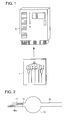
- the microchip is a plate shaped chip that is made of a material such as resin and micro flow channels are provided inside the chip.
- Various fluids such as reagents are flowed into the injection port provided at the upstream side of the microchip 1 by injecting drive fluid that is driven by liquid flowing means such as an independent drive pump, and by moving the drive fluid in the forward and reverse direction by a micropump.
- the microchip 1, the temperature control device, the optical detection device and the like are incorporated into the analysis device 2, and by loading the microchip 1 into the analysis device 2, the series of analysis operation can be performed automatically.
- the biotin modified primer is used to amplify the gene in the flow channel of the microchip 1 and the amplified gene is denatured to form a single strand.
- the resultant solution (called first reagent hereinafter) is flowed into the flow channel on the wall of which a biotinophilic protein such as streptavidin is carried and fixed.
- the gene is fixed in the wall of the flow channel due to the bonding reaction between the biotinophilic protein and the biotin.
- a probe DNA (called second reagent hereinafter) whose end has been fluorescently labelled with FITC is flowed into the flow channel and hybridized with the fixed gene.
- the solution of the gold colloid (called third reagent hereinafter) whose surface has been modified with an anti-FITC antibody which bonds specifically with FITC flowed into the flow channels and the gold colloid is adsorbed to the FITC modified probe that has been hybridized with the gene.
- the amplified gene is detected by optically measuring the concentration of the adsorbed gold colloid.
- the reacting material in the description below that is carried in the flow channel wall refers to the biotinophilic protein, the gene that has bonded with the biotinophilic protein, or the DNA probe that has been hybridized with the gene.
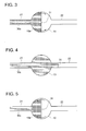
- Fig. 2 - Fig. 5 are explanatory drawings for the flowing of the first reagent into the reaction flow channel in which the reacting material is carried in the first embodiment of this invention.
- 10 denotes the reaction flow channel that has the reacting material carried on its wall surface.
- the operation of feeding the first reagent 30a at the time of reaction will be described sequentially in the following.
- the first reagent 30a is supplied to the reaction flow channel 10 through the upstream flow channel 21 of the reaction flow channel 10.
- the front end 31 of the first reagent 30a passes through the reaction flow channel 10 and reaches to the flow channel 22 ahead of the flow channel 10.
- reaction flow channel 10 is filled with first reagent 30a and then the first reagent 30a is flowed back in the reverse direction such that the front end 31 of the first reagent 30a is put into the reaction flow channel 10 again as shown in Fig. 5 and the peripheral portion of the gas-liquid interface at the front end 31 of the first reagent 30a passes in the reverse direction on the wall surface 10a of the reaction flow channel 10.
- the reagent is flowed once again from the state where the front end 31 of the first reagent 30a is positioned in the reaction flow channel 10 or in the upstream flow channel 21 of the reaction flow channel 10 so that the peripheral portion of the gas-liquid interface at the front end 31 passes through in the forward direction on the wall surface 10a of the reaction flow channel 10.
- the feeding operation is performed at least once, or preferably performed multiple times. Because the peripheral portion of the gas-liquid interface at the front end 31 of the first reagent 30a is moved back and forth and passes a plurality of times on the wall surface 10a of the reaction flow channel 10, movement of the fluid occurs on the wall surface 10a each time the first reagent 30a passes through and thus the situation where the first reagent 30a does not flow and constantly accumulates is prevented. As a result, new contact of the first reagent 30a with the reacting material that is carried on the wall surface 10a progresses and substitution of the reagent with the reacting material on the wall surface 10a is effectively performed. Thus the progress of the reaction is sped up.
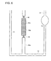
- FIG. 6 - Fig. 9 are explanatory drawings for the flowing of the first and second reagent into the reaction flow channel on which the reacting material is carried in the second embodiment of this invention. It is to be noted that in these drawings, the structural elements which are the same as those in the first embodiment have been assigned the same numbers and descriptions thereof have been omitted.
- the operation is repeated in which the first reagent 30a is flowed into the reaction flow channel 10 and caused to react with the reacting material that is fixed on the flow channel wall and then the second reagent 30b is flowed into the reaction flow channel 10 and caused to react with the reacting material that is fixed on the flow channel wall,
- the second reagent 30b is stored in the reagent holding flow channel 40a.
- a water repellent valve 60 is provided respectively on the upstream end and the downstream end of the reagent holding flow channel 40a, and the second reagent 30b is held in the reagent holding flow channel 40a by these water repellent valves 60.
- Fig. 10 is an exploded view of the water repellent valve.
- the water repellent valve 60 in Fig. 10 comprises a flow control channel 61 which has a narrow flow channel width.
- the cross-sectional area (the cross-sectional area of a vertical cross-section of the flow channel) is smaller than that of the upstream flow channel 62a and the downstream flow channel 62b.
- the flow channel wall is formed of a hydrophobic material such as resin and the like
- passage into the downstream flow channel 62b of the fluid 63 that is in contact with the feed control channel 61 is controlled by the difference in surface tension with respect to the flow channel wall.
- a flow fluid pressure exceeding a predetermined pressure is applied by the micropump in order to cause the fluid 63 to flow out to the downstream flow channel 62b, and as a result, the fluid 63 resists the surface tension and is expelled from the feed control flow channel 61 to the downstream flow channel 62. After the fluid 63 flows out to the flow channel 62b, even if the feed pressure required to expel the front end of the fluid 63 to the downstream flow channel 62b is not maintained, fluid flows to the downstream flow channel 62b.
- feed control flow channel 61 is formed so the width by depth is 25 ⁇ m x 25 ⁇ m for the flow channels 62a and 62b with width by depth of 150 ⁇ m x 300 ⁇ m
- a gas storage flow channel 50a is provided by intervening the water repellent valve 60 at the downstream side of the reagent holding flow channel 40a.
- the first reagent flow channel 71 merges with the gas storage flow channel 50a at the downstream end of the gas storage flow channel 50a, and the gas storage flow channel 50a, communicates with the common flow channel 72.
- the first reagent 30a is supplied from the reagent flow channel 71 to the reaction flow channel 10 through the common flow channel 72.
- the front end of the first reagent 30a moves into the reaction flow channel 10, in the same sequence as that of the first embodiment, the front end moves in the forward and reverse directions between the reaction flow channel 10 and the flow channel 22 ahead thereof.
- the peripheral portion of the gas-liquid interface in the front end of the first reagent 30a passes multiple times on the wall surface of the reaction flow channel 10 on which the reacting material is carried, and thus, new supply and contact of the first reagent 30a with the reacting material that is carried on the wall surface 10a progresses and the reaction is performed.
- the second reagent 30b that is stored in the reagent holding flow channel 40a is expelled from the upstream side by the drive fluid 35 that is driven by the micropump (not shown) and pressure exceeding the fluid holding pressure of the water repellent valve 60 is applied and the second reagent 30b is expelled to the gas storage flow channel 50a.
- the gas that is stored in the gas storage flow channel 50a is pushed out to the common flow channel 72 side and the second reagent 30b is flowed to the reaction flow channel 10 in a state where the gas intervenes at the front end of the second reagent 3b.
- the front end of the second reagent 30b moves in the forward and reverse direction between the reaction flow channel 10 and the flow channel 22 ahead thereof.
- This causes the peripheral portion of the gas-liquid interface at the front end of the second reagent 30b to pass multiple times on the wall surface of the reaction flow channel 10 which carries the reacting material.
- the reacting material carried on the wall surface reacts with the second reagent 30b while accelerating new supply and contact of the second reagent 30b with the reacting material.
- this embodiment allows gas to intervene at the front end of the second reagent 30b, which can accelerate the reaction while moving back and forth the gas-liquid interface at the front end on the wall surface of the reaction flow channel 10, as the case with the first reagent 30a and the second reagent 30b.
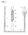
- Fig. 11 is an explanatory drawing for the flowing of the first to third reagents into the reaction flow channel on which the reacting material is carried in the third embodiment of this invention.
- the first reagent 30a is flowed into the reaction flow channel 10 and caused to react with the reacting material that is fixed in the flow channel wall and then the second reagent 30b is flowed into the reaction flow channel 10 and caused to react with the reacting material that is fixed in the flow channel wall.
- the third reagent 30c is flowed into the reaction flow channel 10 and caused to react with the reacting material that is fixed in the flow channel wall.
- the second reagent 30b is stored in the reagent holding flow channel 40a and the third reagent 30c is stored in the reagent holding flow channel 40a.
- a water repellent valve 60 is provided on the upstream end and the downstream end respectively of the reagent holding flow channel 40a, and the second reagent 30b is held in the reagent holding flow channel 40a by these water repellent valves 60.
- the third reagent 30c is held in the reagent holding flow channel 40b by two water repellent valves 60
- a gas storage flow channel 50a is provided at the downstream side of the reagent holding flow channel 40a through the water repellent valve 60.
- the gas storage flow channel 50a merges with the first reagent flow channel 71 at the downstream end of the gas storage flow channel 50a and communicates with the common flow channel 72.
- the gas storage flow channel 50b is provided at the downstream side of the reagent holding flow channel 40b through the water repellent valve 60.
- the gas storage flow channel 50b merges with the first reagent flow channel 71 at the downstream end of the gas storage flow channel 50b and communicates with the common flow channel 72.
- the first reagent 30a is supplied from the first reagent flow channel 71 to the reaction flow channel 10 through the common flow channel 72 and after the front end of the first reagent 30a is moved into the reaction flow channel 10, in the same sequence as that of the first embodiment, the front end moves in the forward and reverse directions between the reaction flow channel 10 and the flow channel 22 in the front thereof.
- This causes the peripheral portion of the gas-liquid interface at the front end of the first reagent 30a to pass multiple times on the wall surface of the reaction flow channel 10 which carries the reacting material.
- the reacting material carried on the wall surface reacts with the second reagent 30b while accelerating new supply and contact of the first reagent 30a with the reacting material.
- drive fluid is injected from the drive fluid injection port 81a in the chip that communicates with the micropump (not shown), the injection port being the opening provided upstream of the drive fluid flow channel 82a.
- the second reagent 30b that is stored in the reagent holding flow channel 40a is pushed from the upstream side and pressure exceeding the fluid holding pressure of the water repellent valve 60 is applied and the second reagent 30b is expelled to the downstream side.
- 83a is a gas vent channel for removing gas bubbles between the drive fluid injected from the drive fluid injection port 81a and the second reagent 30b to the outside. More specifically, 83a is a narrow flow channel that controls the passage of fluid inside the flow channel due to water repellent property or high flow channel resistance and which has an end for removing gas bubbles from the inside of the flow channel to the outside.
- the gas that is stored in the gas storage flow channel 50a is pushed out to the common flow channel 72 side and the second reagent 30b is fed to the reaction flow channel 10 in a state where the gas intervenes, at the second reagent 30b front end side.
- the front end of the second reagent 30b is moved into the reaction flow channel 10, in the same sequence as above, the front end moves in the forward and reverse directions between the reaction flow channel 10 and the flow channel 22 ahead thereof.
- This causes the peripheral portion of the gas-liquid interface at the front end of the second reagent 30b to pass multiple times on the wall surface of the reaction flow channel 10 which carries the reacting material.
- the reacting material carried on the wall surface reacts with the second reagent 30b while accelerating new supply and contact of the second reagent 30b with the reacting material.
- drive fluid is injected from the drive fluid injection port 81b and the third reagent 30c that is stored in the reagent holding flow channel 40b is pushed from the upstream side and pressure exceeding the fluid holding pressure of the water repellent valve 60 is applied and the third reagent 30c is pushed out to the downstream side.
- the gas that is stored in the gas storage flow channel 50a is expelled to the common flow channel 72 side and the third reagent 30c is flowed to the reaction flow channel 10 in a state where the gas intervenes at the third reagent 30c front end side.
- the front end of the third reagent 30c is moved into the reaction flow channel 10, in the same sequence as above, the front end moves in the forward and reverse directions between the reaction flow channel 10 and the flow channel 22 ahead thereof.
- This causes the peripheral portion of the gas-liquid interface at the front end of the second reagent 30b to pass multiple times on the wall surface of the reaction flow channel 10 which carries the reacting material.
- the reacting material carried on the wall surface reacts with the third reagent 30c while accelerating new supply and contact of the third reagent 30c with the reacting material.
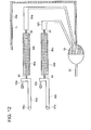
- Fig. 12 shows the flow channel for describing the modified example of the third embodiment.
- the common flow channel 72 is not provided as in Fig. 11 and the gas storage flow channels 50a and 50b are directly connected to the reaction flow channels respectively.
- the feeding operation is performed in the same manner as described in the third embodiment, and the first to third reagents are flowed to the reaction flow channel 10 in a state where the gas intervenes at each front end of the first to third reagents. This can accelerate the reaction by passing multi times the peripheral portion of the gas-liquid interface on the wall surface of the reaction flow channel 10 in which the reacting material is fixed.
- the flow channel 22 As a closed airtight space from the point of the reaction flow channel 10 forward, reagent is flowed to the reaction flow channel 10 by the fluid feeding micropump and then the reagent returns to the reaction flow channel 10 side when pressure falls due to the driving of the micropump being stopped, because the gas space inside the flow channel 22 is compressed by the reagent.
- the flow channel 22 with the closed end acts as a damper and the reagent is able to move back and forth inside the reaction flow channel 10.
- the gas vent channel 83a (83b) is preferably provided at a position before of the reaction flow channel 10 as shown in Fig. 11 .
- the reagent is pressure-flowed to the reaction flow channel 10 using the micropump for flowing fluid, by stopping the micropump, the reagent returns to the reaction flow channel 10 side and the front end of the reagent returns to the position of the gas vent channel where the gas is vented to the atmosphere because the gas space in the flow channel 22 described above is compressed by the reagent.
- the complex control of the micropump is not necessary and the reagent can easily move back and forth inside the reaction flow channel 10.
Landscapes
- Chemical & Material Sciences (AREA)
- Health & Medical Sciences (AREA)
- Life Sciences & Earth Sciences (AREA)
- Analytical Chemistry (AREA)
- General Health & Medical Sciences (AREA)
- Dispersion Chemistry (AREA)
- Chemical Kinetics & Catalysis (AREA)
- Immunology (AREA)
- Physics & Mathematics (AREA)
- Pathology (AREA)
- General Physics & Mathematics (AREA)
- Hematology (AREA)
- Clinical Laboratory Science (AREA)
- Biochemistry (AREA)
- Molecular Biology (AREA)
- Electrochemistry (AREA)
- Automatic Analysis And Handling Materials Therefor (AREA)
- Physical Or Chemical Processes And Apparatus (AREA)
Applications Claiming Priority (2)
| Application Number | Priority Date | Filing Date | Title |
|---|---|---|---|
| JP2006092295 | 2006-03-29 | ||
| PCT/JP2007/053163 WO2007122850A1 (ja) | 2006-03-29 | 2007-02-21 | マイクロチップの流路内における反応方法及び分析装置 |
Publications (3)
| Publication Number | Publication Date |
|---|---|
| EP2000807A1 true EP2000807A1 (de) | 2008-12-10 |
| EP2000807A4 EP2000807A4 (de) | 2012-03-21 |
| EP2000807B1 EP2000807B1 (de) | 2013-04-24 |
Family
ID=38624767
Family Applications (1)
| Application Number | Title | Priority Date | Filing Date |
|---|---|---|---|
| EP07714663.7A Not-in-force EP2000807B1 (de) | 2006-03-29 | 2007-02-21 | Reaktionsverfahren in einem mikrochip-kanal und analysegerät |
Country Status (4)
| Country | Link |
|---|---|
| US (2) | US20090233378A1 (de) |
| EP (1) | EP2000807B1 (de) |
| JP (1) | JP5077227B2 (de) |
| WO (1) | WO2007122850A1 (de) |
Cited By (2)
| Publication number | Priority date | Publication date | Assignee | Title |
|---|---|---|---|---|
| ITTO20100321A1 (it) * | 2010-04-20 | 2011-10-21 | Eltek Spa | Dispositivi microfluidici e/o attrezzature per dispositivi microfluidici |
| WO2011132164A1 (en) * | 2010-04-20 | 2011-10-27 | Eltek S.P.A. | Microfluidic devices and/or equipment for microfluidic devices |
Families Citing this family (4)
| Publication number | Priority date | Publication date | Assignee | Title |
|---|---|---|---|---|
| JP2009121984A (ja) * | 2007-11-15 | 2009-06-04 | Fujifilm Corp | マイクロ流路内泡除去方法及びマイクロ流路内溶解分散方法 |
| JP5155800B2 (ja) * | 2008-09-29 | 2013-03-06 | 富士フイルム株式会社 | 反応方法及び反応装置 |
| GB201103917D0 (en) * | 2011-03-08 | 2011-04-20 | Univ Leiden | Apparatus for and methods of processing liquids or liquid based substances |
| CN113125693B (zh) * | 2021-03-08 | 2022-09-16 | 中山大学 | 一种小型便携式全自动酶联免疫分析仪及其应用 |
Family Cites Families (22)
| Publication number | Priority date | Publication date | Assignee | Title |
|---|---|---|---|---|
| US6132685A (en) * | 1998-08-10 | 2000-10-17 | Caliper Technologies Corporation | High throughput microfluidic systems and methods |
| JP2003522963A (ja) * | 2000-02-18 | 2003-07-29 | アクララ バイオサイエンシーズ, インコーポレイテッド | 複数部位反応デバイスおよび方法 |
| US6681616B2 (en) * | 2000-02-23 | 2004-01-27 | Caliper Technologies Corp. | Microfluidic viscometer |
| US6358387B1 (en) * | 2000-03-27 | 2002-03-19 | Caliper Technologies Corporation | Ultra high throughput microfluidic analytical systems and methods |
| JP3629405B2 (ja) | 2000-05-16 | 2005-03-16 | コニカミノルタホールディングス株式会社 | マイクロポンプ |
| US8329118B2 (en) * | 2004-09-02 | 2012-12-11 | Honeywell International Inc. | Method and apparatus for determining one or more operating parameters for a microfluidic circuit |
| US6890093B2 (en) * | 2000-08-07 | 2005-05-10 | Nanostream, Inc. | Multi-stream microfludic mixers |
| US6653625B2 (en) * | 2001-03-19 | 2003-11-25 | Gyros Ab | Microfluidic system (MS) |
| WO2003000417A2 (en) | 2001-06-20 | 2003-01-03 | Cytonome, Inc. | Microfluidic system including a virtual wall fluid interface port for interfacing fluids with the microfluidic system |
| US7211442B2 (en) * | 2001-06-20 | 2007-05-01 | Cytonome, Inc. | Microfluidic system including a virtual wall fluid interface port for interfacing fluids with the microfluidic system |
| SE0103109D0 (sv) * | 2001-09-17 | 2001-09-17 | Gyros Microlabs Ab | Detector arrangement with rotary drive in an instrument for analysis of microscale liquid sample volumes |
| US6803568B2 (en) * | 2001-09-19 | 2004-10-12 | Predicant Biosciences, Inc. | Multi-channel microfluidic chip for electrospray ionization |
| JP2003098175A (ja) * | 2001-09-21 | 2003-04-03 | Mitsubishi Chemicals Corp | 測定対象物の測定用チップ,測定対象物の測定装置及び測定対象物の測定方法 |
| US6966880B2 (en) * | 2001-10-16 | 2005-11-22 | Agilent Technologies, Inc. | Universal diagnostic platform |
| US6877892B2 (en) * | 2002-01-11 | 2005-04-12 | Nanostream, Inc. | Multi-stream microfluidic aperture mixers |
| US7238164B2 (en) * | 2002-07-19 | 2007-07-03 | Baxter International Inc. | Systems, methods and apparatuses for pumping cassette-based therapies |
| JP3725109B2 (ja) | 2002-09-19 | 2005-12-07 | 財団法人生産技術研究奨励会 | マイクロ流体デバイス |
| US7932098B2 (en) * | 2002-10-31 | 2011-04-26 | Hewlett-Packard Development Company, L.P. | Microfluidic system utilizing thin-film layers to route fluid |
| JP3988658B2 (ja) | 2003-03-07 | 2007-10-10 | コニカミノルタホールディングス株式会社 | マイクロポンプの制御方法およびマイクロ流体システム |
| JP2005134372A (ja) * | 2003-10-06 | 2005-05-26 | Matsushita Electric Ind Co Ltd | 被検物質測定装置 |
| WO2005108571A1 (ja) * | 2004-05-07 | 2005-11-17 | Konica Minolta Medical & Graphic, Inc. | 検査用マイクロリアクタおよび遺伝子検査装置ならびに遺伝子検査方法 |
| JP3952036B2 (ja) * | 2004-05-13 | 2007-08-01 | コニカミノルタセンシング株式会社 | マイクロ流体デバイス並びに試液の試験方法および試験システム |
-
2007
- 2007-02-21 WO PCT/JP2007/053163 patent/WO2007122850A1/ja not_active Ceased
- 2007-02-21 EP EP07714663.7A patent/EP2000807B1/de not_active Not-in-force
- 2007-02-21 US US12/225,598 patent/US20090233378A1/en not_active Abandoned
- 2007-02-21 JP JP2008511983A patent/JP5077227B2/ja not_active Expired - Fee Related
-
2010
- 2010-06-18 US US12/803,060 patent/US8257974B2/en not_active Expired - Fee Related
Cited By (3)
| Publication number | Priority date | Publication date | Assignee | Title |
|---|---|---|---|---|
| ITTO20100321A1 (it) * | 2010-04-20 | 2011-10-21 | Eltek Spa | Dispositivi microfluidici e/o attrezzature per dispositivi microfluidici |
| WO2011132164A1 (en) * | 2010-04-20 | 2011-10-27 | Eltek S.P.A. | Microfluidic devices and/or equipment for microfluidic devices |
| US9250163B2 (en) | 2010-04-20 | 2016-02-02 | Eltek S.P.A. | Microfluidic devices and/or equipment for microfluidic devices |
Also Published As
| Publication number | Publication date |
|---|---|
| US8257974B2 (en) | 2012-09-04 |
| EP2000807A4 (de) | 2012-03-21 |
| WO2007122850A1 (ja) | 2007-11-01 |
| JPWO2007122850A1 (ja) | 2009-09-03 |
| US20090233378A1 (en) | 2009-09-17 |
| JP5077227B2 (ja) | 2012-11-21 |
| EP2000807B1 (de) | 2013-04-24 |
| US20100261290A1 (en) | 2010-10-14 |
Similar Documents
| Publication | Publication Date | Title |
|---|---|---|
| US7482585B2 (en) | Testing chip and micro integrated analysis system | |
| EP1705543B1 (de) | Mikroanalysensystem | |
| JP4888394B2 (ja) | マイクロリアクタおよびそれを用いた送液方法 | |
| EP1754782A1 (de) | Flüssigkeitsmisch- und reaktionseffizienz verbessernder mikroreaktor | |
| US8257974B2 (en) | Method of reaction in flow channel of microchip and analysis device | |
| US7820109B2 (en) | Testing chip and micro analysis system | |
| JP2007136322A (ja) | 反応物質同士の拡散および反応を効率化したマイクロリアクタ、およびそれを用いた反応方法 | |
| WO2009076904A1 (zh) | 具有溶液储室兼泵体结构的微流体样品舟 | |
| JP4682874B2 (ja) | マイクロリアクタ | |
| JP2007083191A (ja) | マイクロリアクタ | |
| JP2007136379A (ja) | マイクロリアクタおよびその製造方法 | |
| JP4915072B2 (ja) | マイクロリアクタ | |
| JPWO2008087828A1 (ja) | マイクロチップ | |
| JP4687413B2 (ja) | マイクロチップにおける2種類以上の液体の混合方法およびマイクロ総合分析システム | |
| US7811521B2 (en) | Testing microchip and testing apparatus using the same | |
| CN101146607A (zh) | 逆流防止结构、使用该结构的检查用微型芯片以及检查装置 | |
| WO2007058077A1 (ja) | 遺伝子検査方法、遺伝子検査用マイクロリアクタ、および遺伝子検査システム | |
| JP4604834B2 (ja) | 検査用マイクロチップおよびそれを用いた検査装置 | |
| JP2006266925A (ja) | マイクロ総合分析システム | |
| JP2007292506A (ja) | マイクロリアクタおよびマイクロリアクタを用いたマイクロ総合分析システム | |
| JP2006275735A (ja) | マイクロ総合分析システム |
Legal Events
| Date | Code | Title | Description |
|---|---|---|---|
| PUAI | Public reference made under article 153(3) epc to a published international application that has entered the european phase |
Free format text: ORIGINAL CODE: 0009012 |
|
| 17P | Request for examination filed |
Effective date: 20080922 |
|
| AK | Designated contracting states |
Kind code of ref document: A1 Designated state(s): AT BE BG CH CY CZ DE DK EE ES FI FR GB GR HU IE IS IT LI LT LU LV MC NL PL PT RO SE SI SK TR |
|
| A4 | Supplementary search report drawn up and despatched |
Effective date: 20120222 |
|
| RIC1 | Information provided on ipc code assigned before grant |
Ipc: G01N 35/08 20060101AFI20120216BHEP Ipc: G01N 37/00 20060101ALI20120216BHEP |
|
| DAX | Request for extension of the european patent (deleted) | ||
| GRAP | Despatch of communication of intention to grant a patent |
Free format text: ORIGINAL CODE: EPIDOSNIGR1 |
|
| GRAS | Grant fee paid |
Free format text: ORIGINAL CODE: EPIDOSNIGR3 |
|
| GRAA | (expected) grant |
Free format text: ORIGINAL CODE: 0009210 |
|
| AK | Designated contracting states |
Kind code of ref document: B1 Designated state(s): AT BE BG CH CY CZ DE DK EE ES FI FR GB GR HU IE IS IT LI LT LU LV MC NL PL PT RO SE SI SK TR |
|
| REG | Reference to a national code |
Ref country code: GB Ref legal event code: FG4D |
|
| REG | Reference to a national code |
Ref country code: CH Ref legal event code: EP |
|
| REG | Reference to a national code |
Ref country code: AT Ref legal event code: REF Ref document number: 608905 Country of ref document: AT Kind code of ref document: T Effective date: 20130515 |
|
| REG | Reference to a national code |
Ref country code: IE Ref legal event code: FG4D |
|
| REG | Reference to a national code |
Ref country code: DE Ref legal event code: R096 Ref document number: 602007029984 Country of ref document: DE Effective date: 20130620 |
|
| REG | Reference to a national code |
Ref country code: CH Ref legal event code: NV Representative=s name: AMMANN PATENTANWAELTE AG BERN, CH |
|
| REG | Reference to a national code |
Ref country code: NL Ref legal event code: T3 |
|
| REG | Reference to a national code |
Ref country code: AT Ref legal event code: MK05 Ref document number: 608905 Country of ref document: AT Kind code of ref document: T Effective date: 20130424 |
|
| REG | Reference to a national code |
Ref country code: LT Ref legal event code: MG4D |
|
| PG25 | Lapsed in a contracting state [announced via postgrant information from national office to epo] |
Ref country code: AT Free format text: LAPSE BECAUSE OF FAILURE TO SUBMIT A TRANSLATION OF THE DESCRIPTION OR TO PAY THE FEE WITHIN THE PRESCRIBED TIME-LIMIT Effective date: 20130424 Ref country code: SE Free format text: LAPSE BECAUSE OF FAILURE TO SUBMIT A TRANSLATION OF THE DESCRIPTION OR TO PAY THE FEE WITHIN THE PRESCRIBED TIME-LIMIT Effective date: 20130424 Ref country code: LT Free format text: LAPSE BECAUSE OF FAILURE TO SUBMIT A TRANSLATION OF THE DESCRIPTION OR TO PAY THE FEE WITHIN THE PRESCRIBED TIME-LIMIT Effective date: 20130424 Ref country code: IS Free format text: LAPSE BECAUSE OF FAILURE TO SUBMIT A TRANSLATION OF THE DESCRIPTION OR TO PAY THE FEE WITHIN THE PRESCRIBED TIME-LIMIT Effective date: 20130824 Ref country code: BE Free format text: LAPSE BECAUSE OF FAILURE TO SUBMIT A TRANSLATION OF THE DESCRIPTION OR TO PAY THE FEE WITHIN THE PRESCRIBED TIME-LIMIT Effective date: 20130424 Ref country code: GR Free format text: LAPSE BECAUSE OF FAILURE TO SUBMIT A TRANSLATION OF THE DESCRIPTION OR TO PAY THE FEE WITHIN THE PRESCRIBED TIME-LIMIT Effective date: 20130725 Ref country code: ES Free format text: LAPSE BECAUSE OF FAILURE TO SUBMIT A TRANSLATION OF THE DESCRIPTION OR TO PAY THE FEE WITHIN THE PRESCRIBED TIME-LIMIT Effective date: 20130804 Ref country code: SI Free format text: LAPSE BECAUSE OF FAILURE TO SUBMIT A TRANSLATION OF THE DESCRIPTION OR TO PAY THE FEE WITHIN THE PRESCRIBED TIME-LIMIT Effective date: 20130424 Ref country code: FI Free format text: LAPSE BECAUSE OF FAILURE TO SUBMIT A TRANSLATION OF THE DESCRIPTION OR TO PAY THE FEE WITHIN THE PRESCRIBED TIME-LIMIT Effective date: 20130424 Ref country code: PT Free format text: LAPSE BECAUSE OF FAILURE TO SUBMIT A TRANSLATION OF THE DESCRIPTION OR TO PAY THE FEE WITHIN THE PRESCRIBED TIME-LIMIT Effective date: 20130826 |
|
| PG25 | Lapsed in a contracting state [announced via postgrant information from national office to epo] |
Ref country code: PL Free format text: LAPSE BECAUSE OF FAILURE TO SUBMIT A TRANSLATION OF THE DESCRIPTION OR TO PAY THE FEE WITHIN THE PRESCRIBED TIME-LIMIT Effective date: 20130424 Ref country code: BG Free format text: LAPSE BECAUSE OF FAILURE TO SUBMIT A TRANSLATION OF THE DESCRIPTION OR TO PAY THE FEE WITHIN THE PRESCRIBED TIME-LIMIT Effective date: 20130724 Ref country code: LV Free format text: LAPSE BECAUSE OF FAILURE TO SUBMIT A TRANSLATION OF THE DESCRIPTION OR TO PAY THE FEE WITHIN THE PRESCRIBED TIME-LIMIT Effective date: 20130424 Ref country code: CY Free format text: LAPSE BECAUSE OF FAILURE TO SUBMIT A TRANSLATION OF THE DESCRIPTION OR TO PAY THE FEE WITHIN THE PRESCRIBED TIME-LIMIT Effective date: 20130424 |
|
| PG25 | Lapsed in a contracting state [announced via postgrant information from national office to epo] |
Ref country code: SK Free format text: LAPSE BECAUSE OF FAILURE TO SUBMIT A TRANSLATION OF THE DESCRIPTION OR TO PAY THE FEE WITHIN THE PRESCRIBED TIME-LIMIT Effective date: 20130424 Ref country code: EE Free format text: LAPSE BECAUSE OF FAILURE TO SUBMIT A TRANSLATION OF THE DESCRIPTION OR TO PAY THE FEE WITHIN THE PRESCRIBED TIME-LIMIT Effective date: 20130424 Ref country code: CZ Free format text: LAPSE BECAUSE OF FAILURE TO SUBMIT A TRANSLATION OF THE DESCRIPTION OR TO PAY THE FEE WITHIN THE PRESCRIBED TIME-LIMIT Effective date: 20130424 Ref country code: DK Free format text: LAPSE BECAUSE OF FAILURE TO SUBMIT A TRANSLATION OF THE DESCRIPTION OR TO PAY THE FEE WITHIN THE PRESCRIBED TIME-LIMIT Effective date: 20130424 |
|
| PG25 | Lapsed in a contracting state [announced via postgrant information from national office to epo] |
Ref country code: IT Free format text: LAPSE BECAUSE OF FAILURE TO SUBMIT A TRANSLATION OF THE DESCRIPTION OR TO PAY THE FEE WITHIN THE PRESCRIBED TIME-LIMIT Effective date: 20130424 Ref country code: RO Free format text: LAPSE BECAUSE OF FAILURE TO SUBMIT A TRANSLATION OF THE DESCRIPTION OR TO PAY THE FEE WITHIN THE PRESCRIBED TIME-LIMIT Effective date: 20130424 |
|
| PLBE | No opposition filed within time limit |
Free format text: ORIGINAL CODE: 0009261 |
|
| STAA | Information on the status of an ep patent application or granted ep patent |
Free format text: STATUS: NO OPPOSITION FILED WITHIN TIME LIMIT |
|
| 26N | No opposition filed |
Effective date: 20140127 |
|
| REG | Reference to a national code |
Ref country code: DE Ref legal event code: R097 Ref document number: 602007029984 Country of ref document: DE Effective date: 20140127 |
|
| PG25 | Lapsed in a contracting state [announced via postgrant information from national office to epo] |
Ref country code: LU Free format text: LAPSE BECAUSE OF FAILURE TO SUBMIT A TRANSLATION OF THE DESCRIPTION OR TO PAY THE FEE WITHIN THE PRESCRIBED TIME-LIMIT Effective date: 20140221 Ref country code: MC Free format text: LAPSE BECAUSE OF FAILURE TO SUBMIT A TRANSLATION OF THE DESCRIPTION OR TO PAY THE FEE WITHIN THE PRESCRIBED TIME-LIMIT Effective date: 20130424 |
|
| REG | Reference to a national code |
Ref country code: IE Ref legal event code: MM4A |
|
| PG25 | Lapsed in a contracting state [announced via postgrant information from national office to epo] |
Ref country code: IE Free format text: LAPSE BECAUSE OF NON-PAYMENT OF DUE FEES Effective date: 20140221 |
|
| REG | Reference to a national code |
Ref country code: FR Ref legal event code: PLFP Year of fee payment: 10 |
|
| PG25 | Lapsed in a contracting state [announced via postgrant information from national office to epo] |
Ref country code: TR Free format text: LAPSE BECAUSE OF FAILURE TO SUBMIT A TRANSLATION OF THE DESCRIPTION OR TO PAY THE FEE WITHIN THE PRESCRIBED TIME-LIMIT Effective date: 20130424 Ref country code: HU Free format text: LAPSE BECAUSE OF FAILURE TO SUBMIT A TRANSLATION OF THE DESCRIPTION OR TO PAY THE FEE WITHIN THE PRESCRIBED TIME-LIMIT; INVALID AB INITIO Effective date: 20070221 |
|
| REG | Reference to a national code |
Ref country code: FR Ref legal event code: PLFP Year of fee payment: 11 |
|
| REG | Reference to a national code |
Ref country code: FR Ref legal event code: PLFP Year of fee payment: 12 |
|
| PGFP | Annual fee paid to national office [announced via postgrant information from national office to epo] |
Ref country code: GB Payment date: 20200212 Year of fee payment: 14 Ref country code: NL Payment date: 20200212 Year of fee payment: 14 Ref country code: DE Payment date: 20200211 Year of fee payment: 14 |
|
| PGFP | Annual fee paid to national office [announced via postgrant information from national office to epo] |
Ref country code: CH Payment date: 20200213 Year of fee payment: 14 |
|
| PGFP | Annual fee paid to national office [announced via postgrant information from national office to epo] |
Ref country code: FR Payment date: 20200113 Year of fee payment: 14 |
|
| REG | Reference to a national code |
Ref country code: DE Ref legal event code: R119 Ref document number: 602007029984 Country of ref document: DE |
|
| GBPC | Gb: european patent ceased through non-payment of renewal fee |
Effective date: 20210221 |
|
| PG25 | Lapsed in a contracting state [announced via postgrant information from national office to epo] |
Ref country code: LI Free format text: LAPSE BECAUSE OF NON-PAYMENT OF DUE FEES Effective date: 20210228 Ref country code: CH Free format text: LAPSE BECAUSE OF NON-PAYMENT OF DUE FEES Effective date: 20210228 |
|
| REG | Reference to a national code |
Ref country code: NL Ref legal event code: MM Effective date: 20210301 |
|
| PG25 | Lapsed in a contracting state [announced via postgrant information from national office to epo] |
Ref country code: NL Free format text: LAPSE BECAUSE OF NON-PAYMENT OF DUE FEES Effective date: 20210301 |
|
| PG25 | Lapsed in a contracting state [announced via postgrant information from national office to epo] |
Ref country code: GB Free format text: LAPSE BECAUSE OF NON-PAYMENT OF DUE FEES Effective date: 20210221 Ref country code: FR Free format text: LAPSE BECAUSE OF NON-PAYMENT OF DUE FEES Effective date: 20210228 Ref country code: DE Free format text: LAPSE BECAUSE OF NON-PAYMENT OF DUE FEES Effective date: 20210901 |