EP2000743A1 - Temperaturausgleichsverfahren und -installation mit einem Wasserversorgungssystem - Google Patents
Temperaturausgleichsverfahren und -installation mit einem Wasserversorgungssystem Download PDFInfo
- Publication number
- EP2000743A1 EP2000743A1 EP07252249A EP07252249A EP2000743A1 EP 2000743 A1 EP2000743 A1 EP 2000743A1 EP 07252249 A EP07252249 A EP 07252249A EP 07252249 A EP07252249 A EP 07252249A EP 2000743 A1 EP2000743 A1 EP 2000743A1
- Authority
- EP
- European Patent Office
- Prior art keywords
- water pipe
- closed
- fluid
- temperature
- piping
- Prior art date
- Legal status (The legal status is an assumption and is not a legal conclusion. Google has not performed a legal analysis and makes no representation as to the accuracy of the status listed.)
- Granted
Links
- XLYOFNOQVPJJNP-UHFFFAOYSA-N water Substances O XLYOFNOQVPJJNP-UHFFFAOYSA-N 0.000 title claims abstract description 542
- 238000009434 installation Methods 0.000 title claims description 167
- 238000000034 method Methods 0.000 title claims description 52
- 239000003673 groundwater Substances 0.000 claims abstract 2
- 239000012530 fluid Substances 0.000 claims description 261
- 238000011067 equilibration Methods 0.000 claims description 234
- 230000005540 biological transmission Effects 0.000 claims description 113
- 238000005253 cladding Methods 0.000 claims description 54
- 239000000463 material Substances 0.000 claims description 40
- 239000007788 liquid Substances 0.000 claims description 38
- 238000010276 construction Methods 0.000 claims description 16
- 230000009349 indirect transmission Effects 0.000 claims description 10
- 239000002184 metal Substances 0.000 claims description 10
- 238000001914 filtration Methods 0.000 claims description 8
- 239000012774 insulation material Substances 0.000 claims description 4
- 238000004378 air conditioning Methods 0.000 claims description 3
- 239000000969 carrier Substances 0.000 claims description 2
- 238000001816 cooling Methods 0.000 claims description 2
- 230000005611 electricity Effects 0.000 claims description 2
- 239000007787 solid Substances 0.000 claims description 2
- 239000000126 substance Substances 0.000 claims description 2
- 238000009825 accumulation Methods 0.000 description 2
- 238000010438 heat treatment Methods 0.000 description 2
- 239000000446 fuel Substances 0.000 description 1
- 238000007689 inspection Methods 0.000 description 1
- 238000002844 melting Methods 0.000 description 1
- 230000008018 melting Effects 0.000 description 1
Images


Classifications
-
- E—FIXED CONSTRUCTIONS
- E03—WATER SUPPLY; SEWERAGE
- E03B—INSTALLATIONS OR METHODS FOR OBTAINING, COLLECTING, OR DISTRIBUTING WATER
- E03B11/00—Arrangements or adaptations of tanks for water supply
- E03B11/10—Arrangements or adaptations of tanks for water supply for public or like main water supply
- E03B11/14—Arrangements or adaptations of tanks for water supply for public or like main water supply of underground tanks
-
- F—MECHANICAL ENGINEERING; LIGHTING; HEATING; WEAPONS; BLASTING
- F24—HEATING; RANGES; VENTILATING
- F24D—DOMESTIC- OR SPACE-HEATING SYSTEMS, e.g. CENTRAL HEATING SYSTEMS; DOMESTIC HOT-WATER SUPPLY SYSTEMS; ELEMENTS OR COMPONENTS THEREFOR
- F24D11/00—Central heating systems using heat accumulated in storage masses
-
- E—FIXED CONSTRUCTIONS
- E03—WATER SUPPLY; SEWERAGE
- E03B—INSTALLATIONS OR METHODS FOR OBTAINING, COLLECTING, OR DISTRIBUTING WATER
- E03B11/00—Arrangements or adaptations of tanks for water supply
-
- F—MECHANICAL ENGINEERING; LIGHTING; HEATING; WEAPONS; BLASTING
- F24—HEATING; RANGES; VENTILATING
- F24F—AIR-CONDITIONING; AIR-HUMIDIFICATION; VENTILATION; USE OF AIR CURRENTS FOR SCREENING
- F24F5/00—Air-conditioning systems or apparatus not covered by F24F1/00 or F24F3/00, e.g. using solar heat or combined with household units such as an oven or water heater
- F24F5/0046—Air-conditioning systems or apparatus not covered by F24F1/00 or F24F3/00, e.g. using solar heat or combined with household units such as an oven or water heater using natural energy, e.g. solar energy, energy from the ground
-
- F—MECHANICAL ENGINEERING; LIGHTING; HEATING; WEAPONS; BLASTING
- F24—HEATING; RANGES; VENTILATING
- F24T—GEOTHERMAL COLLECTORS; GEOTHERMAL SYSTEMS
- F24T10/00—Geothermal collectors
- F24T10/10—Geothermal collectors with circulation of working fluids through underground channels, the working fluids not coming into direct contact with the ground
-
- F—MECHANICAL ENGINEERING; LIGHTING; HEATING; WEAPONS; BLASTING
- F28—HEAT EXCHANGE IN GENERAL
- F28D—HEAT-EXCHANGE APPARATUS, NOT PROVIDED FOR IN ANOTHER SUBCLASS, IN WHICH THE HEAT-EXCHANGE MEDIA DO NOT COME INTO DIRECT CONTACT
- F28D1/00—Heat-exchange apparatus having stationary conduit assemblies for one heat-exchange medium only, the media being in contact with different sides of the conduit wall, in which the other heat-exchange medium is a large body of fluid, e.g. domestic or motor car radiators
- F28D1/02—Heat-exchange apparatus having stationary conduit assemblies for one heat-exchange medium only, the media being in contact with different sides of the conduit wall, in which the other heat-exchange medium is a large body of fluid, e.g. domestic or motor car radiators with heat-exchange conduits immersed in the body of fluid
-
- F—MECHANICAL ENGINEERING; LIGHTING; HEATING; WEAPONS; BLASTING
- F28—HEAT EXCHANGE IN GENERAL
- F28D—HEAT-EXCHANGE APPARATUS, NOT PROVIDED FOR IN ANOTHER SUBCLASS, IN WHICH THE HEAT-EXCHANGE MEDIA DO NOT COME INTO DIRECT CONTACT
- F28D15/00—Heat-exchange apparatus with the intermediate heat-transfer medium in closed tubes passing into or through the conduit walls ; Heat-exchange apparatus employing intermediate heat-transfer medium or bodies
-
- F—MECHANICAL ENGINEERING; LIGHTING; HEATING; WEAPONS; BLASTING
- F24—HEATING; RANGES; VENTILATING
- F24F—AIR-CONDITIONING; AIR-HUMIDIFICATION; VENTILATION; USE OF AIR CURRENTS FOR SCREENING
- F24F5/00—Air-conditioning systems or apparatus not covered by F24F1/00 or F24F3/00, e.g. using solar heat or combined with household units such as an oven or water heater
- F24F5/0046—Air-conditioning systems or apparatus not covered by F24F1/00 or F24F3/00, e.g. using solar heat or combined with household units such as an oven or water heater using natural energy, e.g. solar energy, energy from the ground
- F24F2005/0057—Air-conditioning systems or apparatus not covered by F24F1/00 or F24F3/00, e.g. using solar heat or combined with household units such as an oven or water heater using natural energy, e.g. solar energy, energy from the ground receiving heat-exchange fluid from a closed circuit in the ground
-
- Y—GENERAL TAGGING OF NEW TECHNOLOGICAL DEVELOPMENTS; GENERAL TAGGING OF CROSS-SECTIONAL TECHNOLOGIES SPANNING OVER SEVERAL SECTIONS OF THE IPC; TECHNICAL SUBJECTS COVERED BY FORMER USPC CROSS-REFERENCE ART COLLECTIONS [XRACs] AND DIGESTS
- Y02—TECHNOLOGIES OR APPLICATIONS FOR MITIGATION OR ADAPTATION AGAINST CLIMATE CHANGE
- Y02B—CLIMATE CHANGE MITIGATION TECHNOLOGIES RELATED TO BUILDINGS, e.g. HOUSING, HOUSE APPLIANCES OR RELATED END-USER APPLICATIONS
- Y02B10/00—Integration of renewable energy sources in buildings
- Y02B10/40—Geothermal heat-pumps
-
- Y—GENERAL TAGGING OF NEW TECHNOLOGICAL DEVELOPMENTS; GENERAL TAGGING OF CROSS-SECTIONAL TECHNOLOGIES SPANNING OVER SEVERAL SECTIONS OF THE IPC; TECHNICAL SUBJECTS COVERED BY FORMER USPC CROSS-REFERENCE ART COLLECTIONS [XRACs] AND DIGESTS
- Y02—TECHNOLOGIES OR APPLICATIONS FOR MITIGATION OR ADAPTATION AGAINST CLIMATE CHANGE
- Y02E—REDUCTION OF GREENHOUSE GAS [GHG] EMISSIONS, RELATED TO ENERGY GENERATION, TRANSMISSION OR DISTRIBUTION
- Y02E10/00—Energy generation through renewable energy sources
- Y02E10/10—Geothermal energy
Definitions
- the present invention is related to a methodology and installation for temperature equilibrating conduction, and more particularly, to the use of specific piping from a water supply system and the water running in the pipe as a carrier to conduct the thermal energy in the stratum to a subject matter on the ground.
- the primary purpose of the present invention is to provide a methodology and installation to execute temperature equilibration thermal transmission between the thermal energy in the deeper stratum and a subject matter on the ground designated for transmission of thermal energy by a closed piping comprised of underground water pipe buried in the underground for a water supply system and a closed water pipe disposed on the ground to transmit the thermal energy in the stratum conducted by the underground pipe through the current running in the closed water pipe.
- Fig. 1 is a schematic view showing a layout of a conventional water supply piping and a piping in a building.
- Fig. 2 is a schematic view of the present invention applied in a functional system of thermal equilibration in a building.
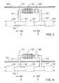
- Fig. 3 is a schematic view showing that the present invention is applied in a construction of a temperature equilibration functional system in shallow stratum.
- Fig. 4 is a schematic view showing that the present invention is applied in a construction of a temperature equilibration functional system exposed from a subject matter on the surface of the earth.
- Fig. 5 is a schematic view showing that the present invention is applied in a construction of a temperature equilibration functional system in a structure on the top of a building.
- Fig. 6 is a schematic view showing that the present invention is applied in a construction of an exposed temperature equilibration functional system on top of a building.
- Fig. 7 is a schematic view of another preferred embodiment yet of the present invention showing that a system of a cladding chamber structure for temperature equilibration is provided to perform open fluid circulation to an open space.
- Fig. 8 is a schematic view of another preferred embodiment yet of the present invention showing that the system includes the cladding chamber structure for temperature equilibration to perform open fluid circulation to an interior space in a building or other closed or semi-closed structure.
- Fig. 9 is a schematic view of another preferred embodiment yet of the present invention showing that the system includes the cladding chamber structure for temperature equilibration to perform closed fluid circulation to an open space.
- Fig. 10 is a schematic view of another preferred embodiment yet of the present invention showing that the system includes the cladding chamber structure for temperature equilibration to perform closed fluid circulation to an interior space in a building or other closed or semi-closed structure.
- Fig. 11 is a schematic view of another preferred embodiment yet of the present invention showing that the system includes an auxiliary temperature equilibration piping disposed in parallel to the present invention so to perform open fluid temperature equilibration circulation to an open space.
- Fig. 12 is a schematic view of another preferred embodiment yet of the present invention showing that the water supply system is disposed with an auxiliary temperature equilibration piping in parallel to the present invention so to perform open fluid circulation to the interior space in a building or other closed or semi-closed structure.
- Fig. 13 is a schematic view of another preferred embodiment yet of the present invention showing that the water supply system is disposed with an auxiliary temperature equilibration piping in parallel to the present invention so to perform closed fluid circulation to an open space.
- Fig. 14 is a schematic view of another preferred embodiment yet of the present invention showing that the water supply system is disposed with an auxiliary temperature equilibration piping in parallel to the present invention so to perform closed fluid circulation to the interior space in a building or other closed or semi-closed structure.
- the present invention of methodology and installation for temperature equilibration by means of a water supply system operates on having an underground water pipe of the conventional water supply system buried in the stratum and water running in the pipe as carriers to be incorporated with a flow passage comprised of a closed water pipe constructed on the ground, a temperature equilibrating object, and a pump.
- the current pumped by the pump functions in the present invention as a carrier of thermal energy to execute thermal transmission of temperature equilibration between the thermal energy in the stratum and a subject matter on ground to receive the thermal energy transmission, thus to replace or support the conventional air conditioning system that consumes massive energy and further to save energy.
- FIG. 1 for a layout of a conventional water supply piping and a piping of a building, wherein,
- the temperature equilibrating methodology and installation by means of the water supply system of the present invention is innovative to provide closed water pipe in a building for the thermal energy in the stratum absorbed by the underground water pipe buried in the stratum to execute thermal transmission of thermal equilibration to the perimeters of the closed water pipe or the temperature equilibration installation in the building through a flow passage created by the thermal equilibration installation, fluid pump and the underground water pipe buried in the stratum with the circulation current as the carrier.
- Fig. 2 is a schematic view of the present invention applied in a functional system of thermal equilibration in a building.
- the present invention is essentially comprised of:
- the methodology and installation of temperature equilibration with the water supply system of the present invention can be also applied to open public facilities. It is a well-known fact that the underground water pipe of a water supply system is usually buried under a highway or other open public facilities and the accumulation of snow on highway or frozen highway will frustrate transportation.
- the methodology and installation of temperature equilibration with the water supply system of the present invention may be also applied in the temperature equilibrating transmission on the surface of the earth in shallow stratum of a highway, or in exposed temperature equilibrating transmission at open public place.
- Fig. 3 is a schematic view showing that the present invention is applied in a construction of a temperature equilibration functional system in shallow stratum.
- the present invention is essentially comprised of:
- Fig. 4 is a schematic view showing that the present invention is applied in a construction of a temperature equilibration functional system exposed from a subject matter on the surface of the earth.
- the present invention is essentially comprised of:
- Fig. 5 is a schematic view showing that the present invention is applied in a construction of a temperature equilibration functional system in a structure on the top of a building.
- the present invention is essentially comprised of:
- Fig. 6 is a schematic view showing that the present invention is applied in a construction of an exposed temperature equilibration functional system on top of a building.
- the present invention is essentially comprised of:
- the temperature equilibrating installation 122 of the methodology and installation of temperature equilibration with a water supply system of the present invention may be optionally provided as follows:
- the temperature equilibrating installation 122 of the methodology and installation of temperature equilibration with a water supply system of the present invention may be provided or not by taking the site of application and cost benefits into consideration.
- the temperature equilibrating function may be achieved by the underground water pipe 103 or the closed water pipe 121 or the closed water pipe in lieu of the temperature equilibrating installation 122; or a structure providing good thermal conduction performance is disposed other than the underground water pipe 103 or the closed water pipe 121 to promote temperature equilibrating function.
- heat insulation material may be provided as required by the work environment or function between the underground water pipe 103 and the closed water pipe 121 exposed or closer to the surface of the earth 101 for the methodology and installation of temperature equilibration with a water supply system of the present invention, or the section of the closed water pipe 121 is made of heat insulation material to prevent loss of thermal energy.
- the linking between the closed water pipe 121 and the underground water pipe 103 in the methodology and installation of temperature equilibration with a water supply system of the present invention may be as such that:
- the water convection effects may be applied to create circulating water, or the flowing force of the current in the underground water pipe 103 is used to create shunting effect for the water flowing through the closed water pipe 121 to serve as a carrier of thermal energy to execute heat transmission of temperature equilibration; in addition to being pumped by the pump 123, the current flowing through the closed water pipe 121 may be found with any of the following patterns:
- the methodology and installation of temperature equilibration with a water supply system of the present invention may be applied at the same time to incorporate a water supply branch 104 to the closed water pipe 121 for certain portion of the conventional water supply branch 104 to serve as a common water pipe to create a closed current flow passage sharing the same structure with certain portion of the closed water pipe 121. If the pump 123 will be provided to the closed current passage sharing the common structure, then
- a cladding chamber structure for temperature equilibration is further provided to the ground or underground water supply piping of the water supply system of the present invention.
- the thermal energy carried by the water current in the water supply piping flows to another gaseous or liquid state fluid of the subject matter into an open space, building, or other closed or semi-closed structure of the subject matter for temperature equilibration to perform the indirect transmission of thermal energy for the purpose of temperature equilibration.
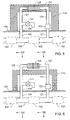
- Fig. 7 shows a schematic view of another preferred embodiment yet of the present invention, wherein a system of a cladding chamber structure for temperature equilibration is provided to perform open fluid circulation to an open space.
- the system includes a cladding chamber structure 220 for temperature equilibration disposed at where surrounds a certain section of the underground water pipe 103 of the water supply system; both end surfaces are closed to the cladding chamber structure 220 for temperature equilibration.
- One or a plurality of fluid inlet 218 and a fluid piping 221 leading to the open space are disposed at one end in the vicinity of the closed end surface; one or a plurality of fluid outlet 219 and a fluid piping 231 leading to the open space are disposed on the other end of the cladding chamber structure 220 to allow the gaseous or liquid state fluid flowing in and out.
- the fluid may perform convection circulation by the effects that the cooler descends and the hotter ascends, or driven by a motor with the installation of a liquid pump 123, or driven by other mechanical kinetics or by manual so to pump the fluid passing through the cladding chamber structure 220 into the fluid piping 221 to the open space.
- the fluid in the open space flows through the fluid piping 231 back to the cladding chamber structure 220 so to perform the temperature equilibration transmission of indirect conduction of thermal energy between the water supply system and the open space.
- the fluid piping 221 and another fluid piping 231 are respectively leading to the open space to perform the open fluid circulation; and the optional filtration device 124 may be each disposed to the fluid inlet and outlet of the fluid piping 221 and another fluid piping 231.
- Fig. 8 shows a schematic view of another preferred embodiment yet of the present invention, wherein the system includes the cladding chamber structure for temperature equilibration to perform open fluid circulation to an interior space in a building or other closed or semi-closed structure.
- the system includes a cladding chamber structure 220 for temperature equilibration disposed at where surrounds a certain section of the underground water pipe 103 of the water supply system; both end surfaces are closed to the cladding chamber structure 220 for temperature equilibration.
- One or a plurality of fluid inlet 218 and the fluid piping 221 leading to the space inside the closed or semi-closed structure in the building 110 are disposed at one end in the vicinity of the closed end surface; one or a plurality of fluid outlet 219 and a fluid piping 231 leading to the space inside the closed or semi-closed structure in the building 110 are disposed on the other end of the cladding chamber structure 220 to allow the gaseous or liquid state fluid flowing in and out.
- the fluid may perform convection circulation by the effects that the cooler descends and the hotter ascends, or driven by a motor with the installation of a liquid pump 123, or driven by other mechanical kinetics or by manual so to pump the fluid passing through the cladding chamber structure 220 into the fluid piping 221 to the space inside the building 110 or other closed or semi-closed structure.
- the fluid then flows through the fluid piping 231 back to the cladding chamber structure 220 so to perform the temperature equilibration transmission of indirect conduction of thermal energy between the water supply system and the space inside the building 110 or other closed or semi-closed structure.
- the fluid piping 221 and another fluid piping 231 are respectively leading to the interior space in the building 110 or other closed or semi-closed structure to perform the open fluid circulation; and the optional filtration device 124 may be each disposed to the fluid inlet and outlet of the fluid piping 221 and another fluid piping 231.
- Fig. 9 shows a schematic view of another preferred embodiment yet of the present invention, wherein the system includes the cladding chamber structure for temperature equilibration to perform closed fluid circulation to an open space.
- the system includes a cladding chamber structure 220 for temperature equilibration disposed at where surrounds a certain section of the underground water pipe 103 of the water supply system; both end surfaces are closed to the cladding chamber structure 220 for temperature equilibration.
- One or a plurality of fluid inlet 218 and the fluid piping 221 leading to the open space are disposed at one end in the vicinity of the closed end surface; one or a plurality of fluid outlet 219 and a fluid piping 231 leading to the open space are disposed on the other end of the cladding chamber structure 220 to allow the gaseous or liquid state fluid flowing in and out.
- the fluid may perform convection circulation by the effects that the cooler descends and the hotter ascends, or driven by a motor with the installation of a liquid pump 123, or driven by other mechanical kinetics or by manual so to pump the fluid passing through the cladding chamber structure 220 into the fluid piping 221 to the temperature equilibrating installation 122 disposed in the open space.
- the fluid then flows through the fluid piping 231 back to the cladding chamber structure 220 so to perform the temperature equilibration transmission of indirect conduction of thermal energy between the water supply system and the open space through temperature equilibrating installation 122.
- the fluid piping 221 and another fluid piping 231 are respectively leading to the temperature equilibrating installation 122 disposed in the open space to perform the closed fluid circulation for transmission of temperature equilibration.
- Fig. 10 shows a schematic view of another preferred embodiment yet of the present invention, wherein the system includes the cladding chamber structure for temperature equilibration to perform closed fluid circulation to an interior space in a building or other closed or semi-closed structure.
- the system includes a cladding chamber structure 220 for temperature equilibration disposed at where surrounds a certain section of the underground water pipe 103 of the water supply system; both end surfaces are closed to the cladding chamber structure 220 for temperature equilibration.
- One or a plurality of fluid inlet 218 and the fluid piping 221 leading to the interior space in a building 110 or a closed or semi-closed structure are disposed at one end in the vicinity of the closed end surface; one or a plurality of fluid outlet 219 and a fluid piping 231 leading to the interior space in a building 110 or a closed or semi-closed structure are disposed on the other end of the cladding chamber structure 220 to allow the gaseous or liquid state fluid flowing in and out.
- the fluid may perform convection circulation by the effects that the cooler descends and the hotter ascends, or driven by a motor with the installation of a liquid pump 123, or driven by other mechanical kinetics or by manual so to pump the fluid passing through the cladding chamber structure 220 into the fluid piping 221 to the temperature equilibrating installation 122 disposed in the interior space in the building 110 or other closed or semi-closed structure.
- the fluid then flows through the fluid piping 231 back to the cladding chamber structure 220 so to perform the temperature equilibration transmission of indirect conduction of thermal energy between the water supply system and the interior space in the building 110 or other closed or semi-closed structure through the temperature equilibrating installation 122.
- the fluid piping 221 and another fluid piping 231 are respectively leading to the temperature equilibrating installation 122 disposed in the interior space in the building 110 or other closed or semi-closed structure to perform the closed fluid circulation for transmission of temperature equilibration.
- an auxiliary temperature equilibration piping may be included in the methodology and installation of temperature equilibration with a water supply system of the present invention to be disposed at where in parallel and allowing mutual transmission of thermal energy with the ground or the underground water supply piping.
- the auxiliary temperature equilibration piping is provided also to allow another type of gaseous or liquid state fluid passing through the piping to the subject matter to indirectly perform the temperature equilibration transmission with the subject matter by utilizing the thermal energy carried by the water current inside the water supply piping of the underground water supply system.
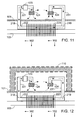
- Fig. 11 shows a schematic view of another preferred embodiment yet of the present invention, wherein the system includes an auxiliary temperature equilibration piping disposed in parallel to the present invention so to perform open fluid temperature equilibration circulation to an open space.
- the system includes one or a plurality of an auxiliary temperature equilibration piping 222 disposed in parallel with and to the perimeter of a certain section of the underground water pipe 103 of the water supply system that is capable of executing transmission of thermal energy mutually with the underground water pipe 103 of the water supply system, and both may be made to share the same construction or interlocked to each other if and when necessarily to facilitate the transmission of thermal energy; or alternatively, a wing shape structure 223 or any other heat conduction structure or heat pipe device may be disposed at where between the water supply system and the auxiliary temperature equilibration piping 222 so to indirectly perform the indirect transmission of thermal energy between the water current inside the underground piping 103 of the water supply system, and the fluid flowing through the auxiliary temperature equilibration piping 222.
- One or a plurality fluid inlet 218 and a fluid piping 221 leading to the open space are disposed to one end of the auxiliary temperature equilibration piping 222; and one or a plurality of fluid outlet 219 and a fluid piping 231 leading to the open space are disposed to the other end of the auxiliary temperature equilibration piping 222 for the gaseous or liquid state fluid to flow in and out.
- the fluid may perform convection circulation by the effects that the cooler descends and the hotter ascends, or driven by a motor with the installation of a liquid pump 123, or driven by other mechanical kinetics or by manual so to pump the fluid passing through the auxiliary temperature equilibration piping 222 into the fluid piping 221 to the open space.
- the fluid then flows through the fluid piping 231 back to the auxiliary temperature equilibration piping 222 so to indirectly perform the temperature equilibration transmission of indirect conduction of thermal energy between the water supply system and the open space.
- the fluid piping 221 and another fluid piping 231 are respectively leading to the open space to perform the open fluid circulation; and the optional filtration device 124 may be each disposed to the fluid inlet and outlet of the fluid piping 221 and another fluid piping 231.
- Fig. 12 shows a schematic view of another preferred embodiment yet of the present invention, wherein the water supply system is disposed with an auxiliary temperature equilibration piping in parallel to the present invention so to perform open fluid circulation to the interior space in a building or other closed or semi-closed structure.
- auxiliary temperature equilibration piping 222 is disposed in parallel with and to the perimeter of a certain section of the underground water pipe 103 of the water supply system.
- the auxiliary temperature equilibration piping 222 is capable of executing transmission of thermal energy mutually with the underground water pipe 103 of the water supply system, and both may be made to share the same construction or interlocked to each other if and when necessarily to facilitate the transmission of thermal energy; or alternatively, a wing shape structure 223 or any other heat conduction structure or heat pipe device may be disposed at where between the water supply system and the auxiliary temperature equilibration piping 222 so to indirectly perform the indirect transmission of thermal energy between the water current inside the underground piping 103 of the water supply system and the fluid flowing though the auxiliary temperature equilibration piping 222.
- One or a plurality fluid inlet 218 and a fluid piping 221 leading to the interior space in the building 110 or other closed or semi-closed structure are disposed to one end of the auxiliary temperature equilibration piping 222; and one or a plurality of fluid outlet 219 and a fluid piping 231 leading to the interior space in the building 110 or a closed or semi-closed structure are disposed to the other end of the auxiliary temperature equilibration piping 222 for the gaseous or liquid state fluid to flow in and out.
- the fluid may perform convection circulation by the effects that the cooler descends and the hotter ascends, or driven by a motor with the installation of a liquid pump 123, or driven by other mechanical kinetics or by manual so to pump the fluid passing through the auxiliary temperature equilibration piping 222 into the fluid piping 221 to the interior space in the building 110 or other closed or semi-closed structure.
- the fluid flows through the fluid piping 231 back to the auxiliary temperature equilibration piping 222 so to indirectly perform the temperature equilibration transmission of indirect conduction of thermal energy between the water supply system and the interior space in the building 110 or a closed or semi-closed structure.
- the fluid piping 221 and another fluid piping 231 are respectively leading to the interior space in the building 110 or other closed or semi-closed structure to perform the open fluid circulation; and the optional filtration device 124 may be each disposed to the fluid inlet and outlet of the fluid piping 221 and another fluid piping 231.
- Fig. 13 shows a schematic view of another preferred embodiment yet of the present invention, wherein the water supply system is disposed with an auxiliary temperature equilibration piping in parallel to the present invention so to perform closed fluid circulation to an open space.
- auxiliary temperature equilibration piping 222 is disposed in parallel with and to the perimeter of a certain section of the underground water pipe 103 of the water supply system.
- the auxiliary temperature equilibration piping 222 is capable of executing transmission of thermal energy mutually with the underground water pipe 103 of the water supply system, and both may be made to share the same construction or interlocked to each other if and when necessarily to facilitate the transmission of thermal energy; or alternatively, a wing shape structure 223 or any other heat conduction structure or heat pipe device may be disposed at where between the water supply system and the auxiliary temperature equilibration piping 222 so to indirectly perform the indirect transmission of thermal energy between the water current inside the underground piping 103 of the water supply system and the fluid flowing though the auxiliary temperature equilibration piping 222.
- One or a plurality fluid inlet 218 and a fluid piping 221 leading to the open space are disposed to one end of the auxiliary temperature equilibration piping 222; and one or a plurality of fluid outlet 219 and a fluid piping 231 leading to the open space are disposed to the other end of the auxiliary temperature equilibration piping 222 for the gaseous or liquid state fluid to flow in and out.
- the fluid may perform convection circulation by the effects that the cooler descends and the hotter ascends, or driven by a motor with the installation of a liquid pump 123, or driven by other mechanical kinetics or by manual so to pump the fluid passing through the auxiliary temperature equilibration piping 222 into the fluid piping 221 to the temperature equilibrating installation 122 disposed in the open space.
- the fluid then flows through the fluid piping 231 back to the auxiliary temperature equilibration piping 222 so to indirectly perform the temperature equilibration transmission of indirect conduction of thermal energy between the water supply system and the open space through the temperature equilibrating installation 122.
- the fluid piping 221 and another fluid piping 231 are respectively leading to the temperature equilibrating installation 122 disposed in the open space of the subject matter to perform the closed fluid circulation for temperature equilibration.
- Fig. 14 shows a schematic view of another preferred embodiment yet of the present invention, wherein the water supply system is disposed with an auxiliary temperature equilibration piping in parallel to the present invention so to perform closed fluid circulation to the interior space in a building or other closed or semi-closed structure.
- auxiliary temperature equilibration piping 222 is disposed in parallel with and to the perimeter of a certain section of the underground water pipe 103 of the water supply system.
- the auxiliary temperature equilibration piping 222 is capable of executing transmission of thermal energy mutually with the underground water pipe 103 of the water supply system, and both may be made to share the same construction or interlocked to each other if and when necessarily to facilitate the transmission of thermal energy; or alternatively, a wing shape structure 223 or any other heat conduction structure or heat pipe device may be disposed at where between the water supply system and the auxiliary temperature equilibration piping 222 so to indirectly perform the indirect transmission of thermal energy between the water current inside the underground piping 103 of the water supply system and the fluid flowing though the auxiliary temperature equilibration piping 222.
- One or a plurality fluid inlet 218 and a fluid piping 221 leading to the interior space in the building 110 or other closed or semi-closed structure are disposed to one end of the auxiliary temperature equilibration piping 222; and one or a plurality of fluid outlet 219 and a fluid piping 231 leading to the interior space in the building 110 or a closed or semi-closed structure are disposed to the other end of the auxiliary temperature equilibration piping 222 for the gaseous or liquid state fluid to flow in and out.
- the fluid may perform convection circulation by the effects that the cooler descends and the hotter ascends, or driven by a motor with the installation of a liquid pump 123, or driven by other mechanical kinetics or by manual so to pump the fluid passing through the auxiliary temperature equilibration piping 222 into the fluid piping 221 to the temperature equilibrating installation 122 disposed in the building 110 or other closed or semi-closed structure.
- the fluid flows through the fluid piping 231 back to cladding temperature equilibration chamber structure 220 so to indirectly perform the temperature equilibration transmission of indirect conduction of thermal energy between the water supply system and the interior space in the building 110 or a closed or semi-closed structure through the temperature equilibrating installation 122.
- the fluid piping 221 and another fluid piping 231 are respectively leading to the temperature equilibrating installation 122 disposed in the interior space in the building 110 or other closed or semi-closed structure to perform the closed fluid circulation for transmission of temperature equilibration.
- the subject matter for the temperature equilibration operation performed by the methodology and installation of temperature equilibration with a water supply system of the present invention includes:
- the building referred in these preferred embodiments described above for the methodology and installation of temperature equilibration with a water supply system of the present invention includes house, warehouse, or any building in column or any other geometric form, or any other designated building comprised of a semi-closed or closed structure designed as desired. Other functioning for the general house to live in, the interior space may be further operated to accommodate:
- the natural thermal energy from the water supply system either cools or maintains the installations and facilities in a certain range of temperature.
- the methodology and installation of temperature equilibration with a water supply system of the present invention by operating on the natural thermal energy (ranging between 12 ⁇ 16 °C) in the stratum absorbed by the underground water pipe of an existing water supply system to have current as a carrier to flow through a closed water pipe disposed at where closer to the surface of the earth, exposed from the ground or in a building to execute heat transmission of temperature equilibration to offer lower cost, summary work, and precise function; therefore, this application for a patent is duly filed.
Landscapes
- Engineering & Computer Science (AREA)
- General Engineering & Computer Science (AREA)
- Mechanical Engineering (AREA)
- Life Sciences & Earth Sciences (AREA)
- Chemical & Material Sciences (AREA)
- Thermal Sciences (AREA)
- Physics & Mathematics (AREA)
- Combustion & Propulsion (AREA)
- Sustainable Energy (AREA)
- Sustainable Development (AREA)
- Health & Medical Sciences (AREA)
- Structural Engineering (AREA)
- Hydrology & Water Resources (AREA)
- Public Health (AREA)
- Water Supply & Treatment (AREA)
- Other Air-Conditioning Systems (AREA)
- Greenhouses (AREA)
- Domestic Plumbing Installations (AREA)
Priority Applications (9)
| Application Number | Priority Date | Filing Date | Title |
|---|---|---|---|
| US11/489,542 US20080028761A1 (en) | 2006-05-30 | 2006-07-20 | Temperature equilibrating methodology & installation with water supply system |
| ES07252249.3T ES2448490T3 (es) | 2007-06-04 | 2007-06-04 | Metodología e instalación para equilibrado de temperatura con un sistema de suministro de agua |
| ES11173696.3T ES2445740T3 (es) | 2007-06-04 | 2007-06-04 | Metodología e instalación para equilibrado de temperatura con un sistema de suministro de agua |
| EP07252249.3A EP2000743B1 (de) | 2007-06-04 | 2007-06-04 | Temperaturausgleichsverfahren und -installation mit einem Wasserversorgungssystem |
| EP11173696.3A EP2383525B1 (de) | 2007-06-04 | 2007-06-04 | Temperaturausgleichsverfahren und -installation mit einem Wasserversorgungssystem |
| TW096125322A TWI534398B (zh) | 2007-06-04 | 2007-07-10 | 藉給水系統作均溫之裝置 |
| CN200710139064XA CN101354153B (zh) | 2007-06-04 | 2007-07-24 | 通过给水系统作均温的装置 |
| KR1020070085360A KR20090020785A (ko) | 2007-06-04 | 2007-08-24 | 급수 시스템에 의한 온도를 균일하게 하는 방법 및 장치 |
| JP2007220209A JP2009052293A (ja) | 2007-06-04 | 2007-08-27 | 給水システムによる温度を均一にする方法及び装置 |
Applications Claiming Priority (1)
| Application Number | Priority Date | Filing Date | Title |
|---|---|---|---|
| EP07252249.3A EP2000743B1 (de) | 2007-06-04 | 2007-06-04 | Temperaturausgleichsverfahren und -installation mit einem Wasserversorgungssystem |
Related Child Applications (1)
| Application Number | Title | Priority Date | Filing Date |
|---|---|---|---|
| EP11173696.3 Division-Into | 2011-07-12 |
Publications (2)
| Publication Number | Publication Date |
|---|---|
| EP2000743A1 true EP2000743A1 (de) | 2008-12-10 |
| EP2000743B1 EP2000743B1 (de) | 2013-12-18 |
Family
ID=38611099
Family Applications (2)
| Application Number | Title | Priority Date | Filing Date |
|---|---|---|---|
| EP07252249.3A Active EP2000743B1 (de) | 2006-05-30 | 2007-06-04 | Temperaturausgleichsverfahren und -installation mit einem Wasserversorgungssystem |
| EP11173696.3A Not-in-force EP2383525B1 (de) | 2007-06-04 | 2007-06-04 | Temperaturausgleichsverfahren und -installation mit einem Wasserversorgungssystem |
Family Applications After (1)
| Application Number | Title | Priority Date | Filing Date |
|---|---|---|---|
| EP11173696.3A Not-in-force EP2383525B1 (de) | 2007-06-04 | 2007-06-04 | Temperaturausgleichsverfahren und -installation mit einem Wasserversorgungssystem |
Country Status (7)
| Country | Link |
|---|---|
| US (1) | US20080028761A1 (de) |
| EP (2) | EP2000743B1 (de) |
| JP (1) | JP2009052293A (de) |
| KR (1) | KR20090020785A (de) |
| CN (1) | CN101354153B (de) |
| ES (2) | ES2445740T3 (de) |
| TW (1) | TWI534398B (de) |
Cited By (1)
| Publication number | Priority date | Publication date | Assignee | Title |
|---|---|---|---|---|
| JP2011226754A (ja) * | 2010-04-20 | 2011-11-10 | Norimasa Sasaki | 太陽熱地中蓄熱装置 |
Families Citing this family (5)
| Publication number | Priority date | Publication date | Assignee | Title |
|---|---|---|---|---|
| US20100018672A1 (en) * | 2008-07-22 | 2010-01-28 | Tai-Her Yang | Conducting type inter-piping fluid thermal energy transfer device |
| US8448876B2 (en) * | 2009-06-12 | 2013-05-28 | Tai-Her Yang | Semiconductor application installation adapted with a temperature equalization system |
| JP5028638B1 (ja) * | 2011-08-09 | 2012-09-19 | 中村物産有限会社 | 地熱利用構造および地熱熱交換器埋設構造 |
| US20130042997A1 (en) * | 2011-08-15 | 2013-02-21 | Tai-Her Yang | Open-loopnatural thermal energy releasing system wtih partialreflux |
| CN107072155B (zh) * | 2014-04-09 | 2020-10-09 | 鲁茨可持续农业技术有限公司 | 热递送系统和方法 |
Citations (6)
| Publication number | Priority date | Publication date | Assignee | Title |
|---|---|---|---|---|
| DE2834442A1 (de) | 1978-08-05 | 1980-02-14 | Ernst Wilhelm Guenther | Verfahren zur gewinnung von haushaltswaerme nach dem waermepumpensystem |
| DE2930484A1 (de) * | 1979-07-27 | 1981-02-12 | Nikolaus Thiel | Verfahren zum betrieb von waermepumpen durch ausnutzung von erdwaerme und anlage zur durchfuehrung des verfahrens |
| US5727621A (en) * | 1995-12-26 | 1998-03-17 | Geotech, Llc (A Non-Incorporated Company) | Geothermal energy means and procedure |
| US6053239A (en) * | 1998-09-04 | 2000-04-25 | Hardin Geotechnologies, Llc. | Geothermal energy means and procedure |
| JP2000146356A (ja) * | 1998-11-13 | 2000-05-26 | Kajima Corp | 分散型ヒートポンプ装置による地域冷暖房システム |
| WO2003012348A2 (en) * | 2001-08-01 | 2003-02-13 | Ace Ronald S | Geothermal space conditioning |
Family Cites Families (23)
| Publication number | Priority date | Publication date | Assignee | Title |
|---|---|---|---|---|
| US508654A (en) * | 1893-11-14 | Cooling transformers | ||
| US827025A (en) * | 1904-04-20 | 1906-07-24 | George Thomas Liddle | Device for thawing frosted fire-hydrants, water-mains, and service-pipes from mains to house-hydrants. |
| US862593A (en) * | 1907-03-05 | 1907-08-06 | Charles C Steiner | Fire-hydrant. |
| US4279294A (en) * | 1978-12-22 | 1981-07-21 | United Technologies Corporation | Heat pipe bag system |
| JPS5816852U (ja) * | 1981-07-26 | 1983-02-02 | ナショナル住宅産業株式会社 | 地中温度の利用装置 |
| JPS608754U (ja) * | 1983-06-29 | 1985-01-22 | 小沢コンクリ−ト工業株式会社 | 水道管の配設構造 |
| US4497365A (en) * | 1983-08-15 | 1985-02-05 | John Boyer | Heat exchanger |
| JPS6122193A (ja) * | 1984-07-05 | 1986-01-30 | Showa Alum Corp | 長尺ヒ−トパイプ |
| JPS639646Y2 (de) * | 1984-12-28 | 1988-03-22 | ||
| JPS61193170U (de) * | 1985-05-21 | 1986-12-01 | ||
| US4880051A (en) * | 1986-07-14 | 1989-11-14 | Kabushiki Kaisha Patine Shokai | Piping apparatus for melting snow and ice |
| JPH0746036B2 (ja) * | 1987-06-16 | 1995-05-17 | 関西電力株式会社 | 地熱利用ヒートパイプの性能検査方法 |
| JPS645058U (de) * | 1987-06-26 | 1989-01-12 | ||
| US5339893A (en) * | 1992-05-08 | 1994-08-23 | The United States Of America As Represented By The Secretary Of The Army | Apparatus for containing toxic spills employing hybrid thermosyphons |
| JPH07224449A (ja) * | 1994-02-10 | 1995-08-22 | Fujikura Ltd | 水道管の凍結防止構造 |
| JPH0833175A (ja) * | 1994-07-11 | 1996-02-02 | Fujikura Ltd | ケーブル用洞道の冷却構造 |
| JPH11256540A (ja) * | 1998-03-11 | 1999-09-21 | Kubota Corp | 下水管路を利用した路面の凍結防止、融雪法 |
| JP3315381B2 (ja) * | 1999-08-24 | 2002-08-19 | 株式会社金正陶器 | 貯水槽 |
| US6267172B1 (en) * | 2000-02-15 | 2001-07-31 | Mcclung, Iii Guy L. | Heat exchange systems |
| JP3485180B2 (ja) * | 2001-03-02 | 2004-01-13 | 芳明 佐々木 | 建物内給排水凍結防止装置 |
| JP2003027534A (ja) * | 2001-07-19 | 2003-01-29 | Masao Fujita | 水道水の常温化装置 |
| US20040108096A1 (en) * | 2002-11-27 | 2004-06-10 | Janssen Terrance Ernest | Geothermal loopless exchanger |
| US20060213637A1 (en) * | 2005-03-25 | 2006-09-28 | Richard Laroche | Geothermal aqueduct network |
-
2006
- 2006-07-20 US US11/489,542 patent/US20080028761A1/en not_active Abandoned
-
2007
- 2007-06-04 EP EP07252249.3A patent/EP2000743B1/de active Active
- 2007-06-04 ES ES11173696.3T patent/ES2445740T3/es active Active
- 2007-06-04 EP EP11173696.3A patent/EP2383525B1/de not_active Not-in-force
- 2007-06-04 ES ES07252249.3T patent/ES2448490T3/es active Active
- 2007-07-10 TW TW096125322A patent/TWI534398B/zh active
- 2007-07-24 CN CN200710139064XA patent/CN101354153B/zh active Active
- 2007-08-24 KR KR1020070085360A patent/KR20090020785A/ko not_active Application Discontinuation
- 2007-08-27 JP JP2007220209A patent/JP2009052293A/ja active Pending
Patent Citations (6)
| Publication number | Priority date | Publication date | Assignee | Title |
|---|---|---|---|---|
| DE2834442A1 (de) | 1978-08-05 | 1980-02-14 | Ernst Wilhelm Guenther | Verfahren zur gewinnung von haushaltswaerme nach dem waermepumpensystem |
| DE2930484A1 (de) * | 1979-07-27 | 1981-02-12 | Nikolaus Thiel | Verfahren zum betrieb von waermepumpen durch ausnutzung von erdwaerme und anlage zur durchfuehrung des verfahrens |
| US5727621A (en) * | 1995-12-26 | 1998-03-17 | Geotech, Llc (A Non-Incorporated Company) | Geothermal energy means and procedure |
| US6053239A (en) * | 1998-09-04 | 2000-04-25 | Hardin Geotechnologies, Llc. | Geothermal energy means and procedure |
| JP2000146356A (ja) * | 1998-11-13 | 2000-05-26 | Kajima Corp | 分散型ヒートポンプ装置による地域冷暖房システム |
| WO2003012348A2 (en) * | 2001-08-01 | 2003-02-13 | Ace Ronald S | Geothermal space conditioning |
Cited By (1)
| Publication number | Priority date | Publication date | Assignee | Title |
|---|---|---|---|---|
| JP2011226754A (ja) * | 2010-04-20 | 2011-11-10 | Norimasa Sasaki | 太陽熱地中蓄熱装置 |
Also Published As
| Publication number | Publication date |
|---|---|
| CN101354153A (zh) | 2009-01-28 |
| EP2383525B1 (de) | 2013-11-27 |
| EP2000743B1 (de) | 2013-12-18 |
| ES2445740T3 (es) | 2014-03-05 |
| EP2383525A1 (de) | 2011-11-02 |
| TW200902923A (en) | 2009-01-16 |
| ES2448490T3 (es) | 2014-03-14 |
| CN101354153B (zh) | 2013-04-17 |
| JP2009052293A (ja) | 2009-03-12 |
| US20080028761A1 (en) | 2008-02-07 |
| KR20090020785A (ko) | 2009-02-27 |
| TWI534398B (zh) | 2016-05-21 |
Similar Documents
| Publication | Publication Date | Title |
|---|---|---|
| Peralta Ramos et al. | Geothermal heat recovery from abandoned mines: a systematic review of projects implemented worldwide and a methodology for screening new projects | |
| Self et al. | Geothermal heat pump systems: Status review and comparison with other heating options | |
| EP2000743A1 (de) | Temperaturausgleichsverfahren und -installation mit einem Wasserversorgungssystem | |
| CN201161766Y (zh) | 一种恒温水箱 | |
| CN101548098B (zh) | 风能转换器、风轮机基础、风轮机基础的方法及应用 | |
| Sanner et al. | Larger geothermal heat pump plants in the central region of Germany | |
| US20130037236A1 (en) | Geothermal facility with thermal recharging of the subsoil | |
| CN101553662A (zh) | 风能转换器及其方法和应用 | |
| KR101462251B1 (ko) | 지중 열교환 시스템 | |
| US5992507A (en) | Geothermal community loop field | |
| US20100018679A1 (en) | Isothermal method and device using periodic direction-change utility water flow | |
| CN110603410B (zh) | 区域能源分配系统 | |
| JP2007303695A (ja) | 自然熱利用冷暖房設備 | |
| Momin | Experimental investigation of geothermal air conditioning | |
| CN203053090U (zh) | 一种间插式地埋管地源热泵系统 | |
| KR101114220B1 (ko) | 고효율 지열 하이브리드 시스템 및 그 작동방법 | |
| JP2020176745A (ja) | ジオ ハイブリッド システム(Geo Hybrid System) | |
| CN2823922Y (zh) | 管中管地热交换器 | |
| US20070295829A1 (en) | Temperature equilibrating methodology & installation with water supply system | |
| Johnston | Geothermal energy using ground source heat pumps | |
| Hytiris et al. | A heat energy recovery system from tunnel waste water | |
| JP2007127397A (ja) | 寒冷な地域における住宅の地中熱利用システム | |
| JP6948711B2 (ja) | 排湯熱再生装置、およびそれを利用した排湯熱再生システム | |
| KR101097910B1 (ko) | 적층수평형 구조의 지열교환기 | |
| KR20220069205A (ko) | 지열 냉난방 시스템 |
Legal Events
| Date | Code | Title | Description |
|---|---|---|---|
| PUAI | Public reference made under article 153(3) epc to a published international application that has entered the european phase |
Free format text: ORIGINAL CODE: 0009012 |
|
| AK | Designated contracting states |
Kind code of ref document: A1 Designated state(s): AT BE BG CH CY CZ DE DK EE ES FI FR GB GR HU IE IS IT LI LT LU LV MC MT NL PL PT RO SE SI SK TR |
|
| AX | Request for extension of the european patent |
Extension state: AL BA HR MK RS |
|
| 17P | Request for examination filed |
Effective date: 20090609 |
|
| 17Q | First examination report despatched |
Effective date: 20090710 |
|
| AKX | Designation fees paid |
Designated state(s): AT BE BG CH CY CZ DE DK EE ES FI FR GB GR HU IE IS IT LI LT LU LV MC MT NL PL PT RO SE SI SK TR |
|
| DAC | Divisional application: reference to earlier application (deleted) | ||
| REG | Reference to a national code |
Ref country code: DE Ref legal event code: R079 Ref document number: 602007034298 Country of ref document: DE Free format text: PREVIOUS MAIN CLASS: F24F0005000000 Ipc: F28D0001020000 |
|
| RIC1 | Information provided on ipc code assigned before grant |
Ipc: F24J 3/08 20060101ALI20130411BHEP Ipc: F28D 15/00 20060101ALI20130411BHEP Ipc: F28D 1/02 20060101AFI20130411BHEP Ipc: F24F 5/00 20060101ALI20130411BHEP |
|
| GRAP | Despatch of communication of intention to grant a patent |
Free format text: ORIGINAL CODE: EPIDOSNIGR1 |
|
| INTG | Intention to grant announced |
Effective date: 20130726 |
|
| GRAS | Grant fee paid |
Free format text: ORIGINAL CODE: EPIDOSNIGR3 |
|
| GRAA | (expected) grant |
Free format text: ORIGINAL CODE: 0009210 |
|
| AK | Designated contracting states |
Kind code of ref document: B1 Designated state(s): AT BE BG CH CY CZ DE DK EE ES FI FR GB GR HU IE IS IT LI LT LU LV MC MT NL PL PT RO SE SI SK TR |
|
| REG | Reference to a national code |
Ref country code: GB Ref legal event code: FG4D |
|
| REG | Reference to a national code |
Ref country code: CH Ref legal event code: EP |
|
| REG | Reference to a national code |
Ref country code: AT Ref legal event code: REF Ref document number: 645810 Country of ref document: AT Kind code of ref document: T Effective date: 20140115 |
|
| REG | Reference to a national code |
Ref country code: IE Ref legal event code: FG4D |
|
| REG | Reference to a national code |
Ref country code: DE Ref legal event code: R096 Ref document number: 602007034298 Country of ref document: DE Effective date: 20140213 |
|
| REG | Reference to a national code |
Ref country code: NL Ref legal event code: T3 |
|
| REG | Reference to a national code |
Ref country code: ES Ref legal event code: FG2A Ref document number: 2448490 Country of ref document: ES Kind code of ref document: T3 Effective date: 20140314 |
|
| PG25 | Lapsed in a contracting state [announced via postgrant information from national office to epo] |
Ref country code: FI Free format text: LAPSE BECAUSE OF FAILURE TO SUBMIT A TRANSLATION OF THE DESCRIPTION OR TO PAY THE FEE WITHIN THE PRESCRIBED TIME-LIMIT Effective date: 20131218 Ref country code: SE Free format text: LAPSE BECAUSE OF FAILURE TO SUBMIT A TRANSLATION OF THE DESCRIPTION OR TO PAY THE FEE WITHIN THE PRESCRIBED TIME-LIMIT Effective date: 20131218 Ref country code: LT Free format text: LAPSE BECAUSE OF FAILURE TO SUBMIT A TRANSLATION OF THE DESCRIPTION OR TO PAY THE FEE WITHIN THE PRESCRIBED TIME-LIMIT Effective date: 20131218 |
|
| REG | Reference to a national code |
Ref country code: AT Ref legal event code: MK05 Ref document number: 645810 Country of ref document: AT Kind code of ref document: T Effective date: 20131218 |
|
| REG | Reference to a national code |
Ref country code: GR Ref legal event code: EP Ref document number: 20140400529 Country of ref document: GR Effective date: 20140416 |
|
| REG | Reference to a national code |
Ref country code: LT Ref legal event code: MG4D |
|
| PG25 | Lapsed in a contracting state [announced via postgrant information from national office to epo] |
Ref country code: LV Free format text: LAPSE BECAUSE OF FAILURE TO SUBMIT A TRANSLATION OF THE DESCRIPTION OR TO PAY THE FEE WITHIN THE PRESCRIBED TIME-LIMIT Effective date: 20131218 |
|
| PG25 | Lapsed in a contracting state [announced via postgrant information from national office to epo] |
Ref country code: EE Free format text: LAPSE BECAUSE OF FAILURE TO SUBMIT A TRANSLATION OF THE DESCRIPTION OR TO PAY THE FEE WITHIN THE PRESCRIBED TIME-LIMIT Effective date: 20131218 Ref country code: BE Free format text: LAPSE BECAUSE OF FAILURE TO SUBMIT A TRANSLATION OF THE DESCRIPTION OR TO PAY THE FEE WITHIN THE PRESCRIBED TIME-LIMIT Effective date: 20131218 Ref country code: IS Free format text: LAPSE BECAUSE OF FAILURE TO SUBMIT A TRANSLATION OF THE DESCRIPTION OR TO PAY THE FEE WITHIN THE PRESCRIBED TIME-LIMIT Effective date: 20140418 |
|
| PG25 | Lapsed in a contracting state [announced via postgrant information from national office to epo] |
Ref country code: AT Free format text: LAPSE BECAUSE OF FAILURE TO SUBMIT A TRANSLATION OF THE DESCRIPTION OR TO PAY THE FEE WITHIN THE PRESCRIBED TIME-LIMIT Effective date: 20131218 Ref country code: SK Free format text: LAPSE BECAUSE OF FAILURE TO SUBMIT A TRANSLATION OF THE DESCRIPTION OR TO PAY THE FEE WITHIN THE PRESCRIBED TIME-LIMIT Effective date: 20131218 Ref country code: RO Free format text: LAPSE BECAUSE OF FAILURE TO SUBMIT A TRANSLATION OF THE DESCRIPTION OR TO PAY THE FEE WITHIN THE PRESCRIBED TIME-LIMIT Effective date: 20131218 Ref country code: PL Free format text: LAPSE BECAUSE OF FAILURE TO SUBMIT A TRANSLATION OF THE DESCRIPTION OR TO PAY THE FEE WITHIN THE PRESCRIBED TIME-LIMIT Effective date: 20131218 Ref country code: CY Free format text: LAPSE BECAUSE OF FAILURE TO SUBMIT A TRANSLATION OF THE DESCRIPTION OR TO PAY THE FEE WITHIN THE PRESCRIBED TIME-LIMIT Effective date: 20131218 Ref country code: CZ Free format text: LAPSE BECAUSE OF FAILURE TO SUBMIT A TRANSLATION OF THE DESCRIPTION OR TO PAY THE FEE WITHIN THE PRESCRIBED TIME-LIMIT Effective date: 20131218 Ref country code: PT Free format text: LAPSE BECAUSE OF FAILURE TO SUBMIT A TRANSLATION OF THE DESCRIPTION OR TO PAY THE FEE WITHIN THE PRESCRIBED TIME-LIMIT Effective date: 20140418 |
|
| PGFP | Annual fee paid to national office [announced via postgrant information from national office to epo] |
Ref country code: GR Payment date: 20140624 Year of fee payment: 8 |
|
| REG | Reference to a national code |
Ref country code: DE Ref legal event code: R097 Ref document number: 602007034298 Country of ref document: DE |
|
| PLBE | No opposition filed within time limit |
Free format text: ORIGINAL CODE: 0009261 |
|
| STAA | Information on the status of an ep patent application or granted ep patent |
Free format text: STATUS: NO OPPOSITION FILED WITHIN TIME LIMIT |
|
| PG25 | Lapsed in a contracting state [announced via postgrant information from national office to epo] |
Ref country code: DK Free format text: LAPSE BECAUSE OF FAILURE TO SUBMIT A TRANSLATION OF THE DESCRIPTION OR TO PAY THE FEE WITHIN THE PRESCRIBED TIME-LIMIT Effective date: 20131218 |
|
| 26N | No opposition filed |
Effective date: 20140919 |
|
| PGFP | Annual fee paid to national office [announced via postgrant information from national office to epo] |
Ref country code: ES Payment date: 20140728 Year of fee payment: 8 |
|
| REG | Reference to a national code |
Ref country code: DE Ref legal event code: R097 Ref document number: 602007034298 Country of ref document: DE Effective date: 20140919 |
|
| PG25 | Lapsed in a contracting state [announced via postgrant information from national office to epo] |
Ref country code: LU Free format text: LAPSE BECAUSE OF FAILURE TO SUBMIT A TRANSLATION OF THE DESCRIPTION OR TO PAY THE FEE WITHIN THE PRESCRIBED TIME-LIMIT Effective date: 20140604 Ref country code: MC Free format text: LAPSE BECAUSE OF FAILURE TO SUBMIT A TRANSLATION OF THE DESCRIPTION OR TO PAY THE FEE WITHIN THE PRESCRIBED TIME-LIMIT Effective date: 20131218 |
|
| REG | Reference to a national code |
Ref country code: CH Ref legal event code: PL |
|
| REG | Reference to a national code |
Ref country code: IE Ref legal event code: MM4A |
|
| PG25 | Lapsed in a contracting state [announced via postgrant information from national office to epo] |
Ref country code: IE Free format text: LAPSE BECAUSE OF NON-PAYMENT OF DUE FEES Effective date: 20140604 Ref country code: LI Free format text: LAPSE BECAUSE OF NON-PAYMENT OF DUE FEES Effective date: 20140630 Ref country code: CH Free format text: LAPSE BECAUSE OF NON-PAYMENT OF DUE FEES Effective date: 20140630 |
|
| PG25 | Lapsed in a contracting state [announced via postgrant information from national office to epo] |
Ref country code: SI Free format text: LAPSE BECAUSE OF FAILURE TO SUBMIT A TRANSLATION OF THE DESCRIPTION OR TO PAY THE FEE WITHIN THE PRESCRIBED TIME-LIMIT Effective date: 20131218 |
|
| REG | Reference to a national code |
Ref country code: FR Ref legal event code: PLFP Year of fee payment: 9 |
|
| PG25 | Lapsed in a contracting state [announced via postgrant information from national office to epo] |
Ref country code: IT Free format text: LAPSE BECAUSE OF NON-PAYMENT OF DUE FEES Effective date: 20150604 |
|
| PG25 | Lapsed in a contracting state [announced via postgrant information from national office to epo] |
Ref country code: MT Free format text: LAPSE BECAUSE OF FAILURE TO SUBMIT A TRANSLATION OF THE DESCRIPTION OR TO PAY THE FEE WITHIN THE PRESCRIBED TIME-LIMIT Effective date: 20131218 |
|
| PGRI | Patent reinstated in contracting state [announced from national office to epo] |
Ref country code: IT Effective date: 20160412 |
|
| PG25 | Lapsed in a contracting state [announced via postgrant information from national office to epo] |
Ref country code: GR Free format text: LAPSE BECAUSE OF NON-PAYMENT OF DUE FEES Effective date: 20160112 Ref country code: BG Free format text: LAPSE BECAUSE OF FAILURE TO SUBMIT A TRANSLATION OF THE DESCRIPTION OR TO PAY THE FEE WITHIN THE PRESCRIBED TIME-LIMIT Effective date: 20131218 |
|
| REG | Reference to a national code |
Ref country code: GR Ref legal event code: ML Ref document number: 20140400529 Country of ref document: GR Effective date: 20160112 |
|
| REG | Reference to a national code |
Ref country code: FR Ref legal event code: PLFP Year of fee payment: 10 |
|
| PG25 | Lapsed in a contracting state [announced via postgrant information from national office to epo] |
Ref country code: TR Free format text: LAPSE BECAUSE OF FAILURE TO SUBMIT A TRANSLATION OF THE DESCRIPTION OR TO PAY THE FEE WITHIN THE PRESCRIBED TIME-LIMIT Effective date: 20131218 Ref country code: HU Free format text: LAPSE BECAUSE OF FAILURE TO SUBMIT A TRANSLATION OF THE DESCRIPTION OR TO PAY THE FEE WITHIN THE PRESCRIBED TIME-LIMIT; INVALID AB INITIO Effective date: 20070604 |
|
| REG | Reference to a national code |
Ref country code: ES Ref legal event code: FD2A Effective date: 20161202 |
|
| PG25 | Lapsed in a contracting state [announced via postgrant information from national office to epo] |
Ref country code: ES Free format text: LAPSE BECAUSE OF NON-PAYMENT OF DUE FEES Effective date: 20150605 |
|
| REG | Reference to a national code |
Ref country code: FR Ref legal event code: PLFP Year of fee payment: 11 |
|
| PGFP | Annual fee paid to national office [announced via postgrant information from national office to epo] |
Ref country code: FR Payment date: 20170630 Year of fee payment: 11 Ref country code: GB Payment date: 20170630 Year of fee payment: 11 |
|
| PGFP | Annual fee paid to national office [announced via postgrant information from national office to epo] |
Ref country code: NL Payment date: 20170629 Year of fee payment: 11 |
|
| PGFP | Annual fee paid to national office [announced via postgrant information from national office to epo] |
Ref country code: IT Payment date: 20170630 Year of fee payment: 11 |
|
| REG | Reference to a national code |
Ref country code: NL Ref legal event code: MM Effective date: 20180701 |
|
| GBPC | Gb: european patent ceased through non-payment of renewal fee |
Effective date: 20180604 |
|
| PG25 | Lapsed in a contracting state [announced via postgrant information from national office to epo] |
Ref country code: NL Free format text: LAPSE BECAUSE OF NON-PAYMENT OF DUE FEES Effective date: 20180701 |
|
| PG25 | Lapsed in a contracting state [announced via postgrant information from national office to epo] |
Ref country code: FR Free format text: LAPSE BECAUSE OF NON-PAYMENT OF DUE FEES Effective date: 20180630 Ref country code: GB Free format text: LAPSE BECAUSE OF NON-PAYMENT OF DUE FEES Effective date: 20180604 Ref country code: IT Free format text: LAPSE BECAUSE OF NON-PAYMENT OF DUE FEES Effective date: 20180604 |
|
| REG | Reference to a national code |
Ref country code: DE Ref legal event code: R082 Ref document number: 602007034298 Country of ref document: DE Representative=s name: MEISSNER BOLTE PATENTANWAELTE RECHTSANWAELTE P, DE |
|
| PGFP | Annual fee paid to national office [announced via postgrant information from national office to epo] |
Ref country code: DE Payment date: 20230719 Year of fee payment: 17 |