EP2000733B1 - Actionnement magnétique miniature panoramique horizontal/vertical à bas coût pour caméras vidéo stationnaires et portables - Google Patents
Actionnement magnétique miniature panoramique horizontal/vertical à bas coût pour caméras vidéo stationnaires et portables Download PDFInfo
- Publication number
- EP2000733B1 EP2000733B1 EP08157386A EP08157386A EP2000733B1 EP 2000733 B1 EP2000733 B1 EP 2000733B1 EP 08157386 A EP08157386 A EP 08157386A EP 08157386 A EP08157386 A EP 08157386A EP 2000733 B1 EP2000733 B1 EP 2000733B1
- Authority
- EP
- European Patent Office
- Prior art keywords
- tilt
- pan
- magnetic structure
- axis
- mirror
- Prior art date
- Legal status (The legal status is an assumption and is not a legal conclusion. Google has not performed a legal analysis and makes no representation as to the accuracy of the status listed.)
- Ceased
Links
- 230000005291 magnetic effect Effects 0.000 title claims description 158
- 230000003287 optical effect Effects 0.000 claims description 76
- 230000007246 mechanism Effects 0.000 claims description 42
- 238000004091 panning Methods 0.000 claims description 20
- 230000008859 change Effects 0.000 claims description 9
- 239000000725 suspension Substances 0.000 claims description 9
- 238000003384 imaging method Methods 0.000 claims description 8
- 238000013016 damping Methods 0.000 claims description 6
- 239000003302 ferromagnetic material Substances 0.000 claims description 6
- 239000012530 fluid Substances 0.000 claims description 5
- 230000002093 peripheral effect Effects 0.000 claims description 3
- 238000000034 method Methods 0.000 description 33
- 239000000463 material Substances 0.000 description 26
- 239000000758 substrate Substances 0.000 description 23
- 229910052751 metal Inorganic materials 0.000 description 21
- 239000002184 metal Substances 0.000 description 21
- PXHVJJICTQNCMI-UHFFFAOYSA-N Nickel Chemical compound [Ni] PXHVJJICTQNCMI-UHFFFAOYSA-N 0.000 description 20
- 230000008569 process Effects 0.000 description 15
- 230000005415 magnetization Effects 0.000 description 10
- 238000007747 plating Methods 0.000 description 10
- 229910052759 nickel Inorganic materials 0.000 description 9
- 229910045601 alloy Inorganic materials 0.000 description 8
- 239000000956 alloy Substances 0.000 description 8
- 238000009713 electroplating Methods 0.000 description 7
- 239000010931 gold Substances 0.000 description 7
- 238000013459 approach Methods 0.000 description 6
- 230000033001 locomotion Effects 0.000 description 6
- 230000008901 benefit Effects 0.000 description 5
- 238000005516 engineering process Methods 0.000 description 4
- 230000005294 ferromagnetic effect Effects 0.000 description 4
- 239000000835 fiber Substances 0.000 description 4
- 239000011888 foil Substances 0.000 description 4
- 229910052737 gold Inorganic materials 0.000 description 4
- 239000000696 magnetic material Substances 0.000 description 4
- 238000004519 manufacturing process Methods 0.000 description 4
- 230000002829 reductive effect Effects 0.000 description 4
- 239000010936 titanium Substances 0.000 description 4
- VYZAMTAEIAYCRO-UHFFFAOYSA-N Chromium Chemical compound [Cr] VYZAMTAEIAYCRO-UHFFFAOYSA-N 0.000 description 3
- 229910021417 amorphous silicon Inorganic materials 0.000 description 3
- 230000015572 biosynthetic process Effects 0.000 description 3
- 239000010949 copper Substances 0.000 description 3
- 238000000151 deposition Methods 0.000 description 3
- 230000004907 flux Effects 0.000 description 3
- 239000011521 glass Substances 0.000 description 3
- PCHJSUWPFVWCPO-UHFFFAOYSA-N gold Chemical compound [Au] PCHJSUWPFVWCPO-UHFFFAOYSA-N 0.000 description 3
- 238000001259 photo etching Methods 0.000 description 3
- XEEYBQQBJWHFJM-UHFFFAOYSA-N Iron Chemical compound [Fe] XEEYBQQBJWHFJM-UHFFFAOYSA-N 0.000 description 2
- 229910003266 NiCo Inorganic materials 0.000 description 2
- 239000004642 Polyimide Substances 0.000 description 2
- BQCADISMDOOEFD-UHFFFAOYSA-N Silver Chemical compound [Ag] BQCADISMDOOEFD-UHFFFAOYSA-N 0.000 description 2
- 241000256247 Spodoptera exigua Species 0.000 description 2
- 229910052782 aluminium Inorganic materials 0.000 description 2
- XAGFODPZIPBFFR-UHFFFAOYSA-N aluminium Chemical compound [Al] XAGFODPZIPBFFR-UHFFFAOYSA-N 0.000 description 2
- 239000011651 chromium Substances 0.000 description 2
- 238000013461 design Methods 0.000 description 2
- 230000000694 effects Effects 0.000 description 2
- 238000005323 electroforming Methods 0.000 description 2
- 238000007772 electroless plating Methods 0.000 description 2
- 230000005686 electrostatic field Effects 0.000 description 2
- 238000005530 etching Methods 0.000 description 2
- 230000006872 improvement Effects 0.000 description 2
- 230000010354 integration Effects 0.000 description 2
- 150000002739 metals Chemical class 0.000 description 2
- 229910001172 neodymium magnet Inorganic materials 0.000 description 2
- 230000007935 neutral effect Effects 0.000 description 2
- 238000004806 packaging method and process Methods 0.000 description 2
- 229910000889 permalloy Inorganic materials 0.000 description 2
- 229920002120 photoresistant polymer Polymers 0.000 description 2
- 229920001721 polyimide Polymers 0.000 description 2
- 230000004044 response Effects 0.000 description 2
- 229910052709 silver Inorganic materials 0.000 description 2
- 239000004332 silver Substances 0.000 description 2
- 238000009987 spinning Methods 0.000 description 2
- 230000003068 static effect Effects 0.000 description 2
- 229910052719 titanium Inorganic materials 0.000 description 2
- IGELFKKMDLGCJO-UHFFFAOYSA-N xenon difluoride Chemical compound F[Xe]F IGELFKKMDLGCJO-UHFFFAOYSA-N 0.000 description 2
- BLIQUJLAJXRXSG-UHFFFAOYSA-N 1-benzyl-3-(trifluoromethyl)pyrrolidin-1-ium-3-carboxylate Chemical compound C1C(C(=O)O)(C(F)(F)F)CCN1CC1=CC=CC=C1 BLIQUJLAJXRXSG-UHFFFAOYSA-N 0.000 description 1
- 229910002546 FeCo Inorganic materials 0.000 description 1
- 229910005335 FePt Inorganic materials 0.000 description 1
- 229910001030 Iron–nickel alloy Inorganic materials 0.000 description 1
- ZOKXTWBITQBERF-UHFFFAOYSA-N Molybdenum Chemical compound [Mo] ZOKXTWBITQBERF-UHFFFAOYSA-N 0.000 description 1
- RTAQQCXQSZGOHL-UHFFFAOYSA-N Titanium Chemical compound [Ti] RTAQQCXQSZGOHL-UHFFFAOYSA-N 0.000 description 1
- 229910001080 W alloy Inorganic materials 0.000 description 1
- 229910001093 Zr alloy Inorganic materials 0.000 description 1
- QJVKUMXDEUEQLH-UHFFFAOYSA-N [B].[Fe].[Nd] Chemical compound [B].[Fe].[Nd] QJVKUMXDEUEQLH-UHFFFAOYSA-N 0.000 description 1
- 239000000654 additive Substances 0.000 description 1
- 239000000853 adhesive Substances 0.000 description 1
- 238000004026 adhesive bonding Methods 0.000 description 1
- 230000001070 adhesive effect Effects 0.000 description 1
- 229910000828 alnico Inorganic materials 0.000 description 1
- 238000000137 annealing Methods 0.000 description 1
- 229910052804 chromium Inorganic materials 0.000 description 1
- 229910017052 cobalt Inorganic materials 0.000 description 1
- 239000010941 cobalt Substances 0.000 description 1
- GUTLYIVDDKVIGB-UHFFFAOYSA-N cobalt atom Chemical compound [Co] GUTLYIVDDKVIGB-UHFFFAOYSA-N 0.000 description 1
- KPLQYGBQNPPQGA-UHFFFAOYSA-N cobalt samarium Chemical compound [Co].[Sm] KPLQYGBQNPPQGA-UHFFFAOYSA-N 0.000 description 1
- 239000004020 conductor Substances 0.000 description 1
- 238000010276 construction Methods 0.000 description 1
- 229910052802 copper Inorganic materials 0.000 description 1
- 230000003247 decreasing effect Effects 0.000 description 1
- 238000010586 diagram Methods 0.000 description 1
- 238000002474 experimental method Methods 0.000 description 1
- 230000006870 function Effects 0.000 description 1
- 230000036039 immunity Effects 0.000 description 1
- 239000012535 impurity Substances 0.000 description 1
- 238000011503 in vivo imaging Methods 0.000 description 1
- 230000003993 interaction Effects 0.000 description 1
- 230000002452 interceptive effect Effects 0.000 description 1
- 229910052742 iron Inorganic materials 0.000 description 1
- 238000003698 laser cutting Methods 0.000 description 1
- 238000010329 laser etching Methods 0.000 description 1
- 230000000670 limiting effect Effects 0.000 description 1
- 229910001092 metal group alloy Inorganic materials 0.000 description 1
- 239000007769 metal material Substances 0.000 description 1
- 239000002480 mineral oil Substances 0.000 description 1
- 235000010446 mineral oil Nutrition 0.000 description 1
- 238000012986 modification Methods 0.000 description 1
- 230000004048 modification Effects 0.000 description 1
- 239000003607 modifier Substances 0.000 description 1
- 239000002991 molded plastic Substances 0.000 description 1
- 229910052750 molybdenum Inorganic materials 0.000 description 1
- 239000011733 molybdenum Substances 0.000 description 1
- ZSJFLDUTBDIFLJ-UHFFFAOYSA-N nickel zirconium Chemical compound [Ni].[Zr] ZSJFLDUTBDIFLJ-UHFFFAOYSA-N 0.000 description 1
- 238000000623 plasma-assisted chemical vapour deposition Methods 0.000 description 1
- 238000005498 polishing Methods 0.000 description 1
- 230000001681 protective effect Effects 0.000 description 1
- 229910052761 rare earth metal Inorganic materials 0.000 description 1
- 150000002910 rare earth metals Chemical class 0.000 description 1
- 238000002310 reflectometry Methods 0.000 description 1
- 230000003014 reinforcing effect Effects 0.000 description 1
- 230000002441 reversible effect Effects 0.000 description 1
- 229910000938 samarium–cobalt magnet Inorganic materials 0.000 description 1
- 238000007789 sealing Methods 0.000 description 1
- 229910001285 shape-memory alloy Inorganic materials 0.000 description 1
- 229920002545 silicone oil Polymers 0.000 description 1
- 230000003746 surface roughness Effects 0.000 description 1
- MAKDTFFYCIMFQP-UHFFFAOYSA-N titanium tungsten Chemical compound [Ti].[W] MAKDTFFYCIMFQP-UHFFFAOYSA-N 0.000 description 1
- 238000013519 translation Methods 0.000 description 1
- WFKWXMTUELFFGS-UHFFFAOYSA-N tungsten Chemical compound [W] WFKWXMTUELFFGS-UHFFFAOYSA-N 0.000 description 1
- 229910052721 tungsten Inorganic materials 0.000 description 1
- 239000010937 tungsten Substances 0.000 description 1
- 229910052720 vanadium Inorganic materials 0.000 description 1
- LEONUFNNVUYDNQ-UHFFFAOYSA-N vanadium atom Chemical compound [V] LEONUFNNVUYDNQ-UHFFFAOYSA-N 0.000 description 1
Images


Classifications
-
- F—MECHANICAL ENGINEERING; LIGHTING; HEATING; WEAPONS; BLASTING
- F16—ENGINEERING ELEMENTS AND UNITS; GENERAL MEASURES FOR PRODUCING AND MAINTAINING EFFECTIVE FUNCTIONING OF MACHINES OR INSTALLATIONS; THERMAL INSULATION IN GENERAL
- F16M—FRAMES, CASINGS OR BEDS OF ENGINES, MACHINES OR APPARATUS, NOT SPECIFIC TO ENGINES, MACHINES OR APPARATUS PROVIDED FOR ELSEWHERE; STANDS; SUPPORTS
- F16M11/00—Stands or trestles as supports for apparatus or articles placed thereon ; Stands for scientific apparatus such as gravitational force meters
- F16M11/20—Undercarriages with or without wheels
- F16M11/2007—Undercarriages with or without wheels comprising means allowing pivoting adjustment
- F16M11/2014—Undercarriages with or without wheels comprising means allowing pivoting adjustment around a vertical axis
-
- F—MECHANICAL ENGINEERING; LIGHTING; HEATING; WEAPONS; BLASTING
- F16—ENGINEERING ELEMENTS AND UNITS; GENERAL MEASURES FOR PRODUCING AND MAINTAINING EFFECTIVE FUNCTIONING OF MACHINES OR INSTALLATIONS; THERMAL INSULATION IN GENERAL
- F16M—FRAMES, CASINGS OR BEDS OF ENGINES, MACHINES OR APPARATUS, NOT SPECIFIC TO ENGINES, MACHINES OR APPARATUS PROVIDED FOR ELSEWHERE; STANDS; SUPPORTS
- F16M11/00—Stands or trestles as supports for apparatus or articles placed thereon ; Stands for scientific apparatus such as gravitational force meters
- F16M11/02—Heads
- F16M11/04—Means for attachment of apparatus; Means allowing adjustment of the apparatus relatively to the stand
- F16M11/06—Means for attachment of apparatus; Means allowing adjustment of the apparatus relatively to the stand allowing pivoting
- F16M11/10—Means for attachment of apparatus; Means allowing adjustment of the apparatus relatively to the stand allowing pivoting around a horizontal axis
-
- F—MECHANICAL ENGINEERING; LIGHTING; HEATING; WEAPONS; BLASTING
- F16—ENGINEERING ELEMENTS AND UNITS; GENERAL MEASURES FOR PRODUCING AND MAINTAINING EFFECTIVE FUNCTIONING OF MACHINES OR INSTALLATIONS; THERMAL INSULATION IN GENERAL
- F16M—FRAMES, CASINGS OR BEDS OF ENGINES, MACHINES OR APPARATUS, NOT SPECIFIC TO ENGINES, MACHINES OR APPARATUS PROVIDED FOR ELSEWHERE; STANDS; SUPPORTS
- F16M11/00—Stands or trestles as supports for apparatus or articles placed thereon ; Stands for scientific apparatus such as gravitational force meters
- F16M11/02—Heads
- F16M11/18—Heads with mechanism for moving the apparatus relatively to the stand
-
- G—PHYSICS
- G02—OPTICS
- G02B—OPTICAL ELEMENTS, SYSTEMS OR APPARATUS
- G02B13/00—Optical objectives specially designed for the purposes specified below
- G02B13/06—Panoramic objectives; So-called "sky lenses" including panoramic objectives having reflecting surfaces
-
- G—PHYSICS
- G02—OPTICS
- G02B—OPTICAL ELEMENTS, SYSTEMS OR APPARATUS
- G02B26/00—Optical devices or arrangements for the control of light using movable or deformable optical elements
- G02B26/08—Optical devices or arrangements for the control of light using movable or deformable optical elements for controlling the direction of light
- G02B26/0816—Optical devices or arrangements for the control of light using movable or deformable optical elements for controlling the direction of light by means of one or more reflecting elements
- G02B26/0833—Optical devices or arrangements for the control of light using movable or deformable optical elements for controlling the direction of light by means of one or more reflecting elements the reflecting element being a micromechanical device, e.g. a MEMS mirror, DMD
- G02B26/085—Optical devices or arrangements for the control of light using movable or deformable optical elements for controlling the direction of light by means of one or more reflecting elements the reflecting element being a micromechanical device, e.g. a MEMS mirror, DMD the reflecting means being moved or deformed by electromagnetic means
-
- H—ELECTRICITY
- H04—ELECTRIC COMMUNICATION TECHNIQUE
- H04N—PICTORIAL COMMUNICATION, e.g. TELEVISION
- H04N23/00—Cameras or camera modules comprising electronic image sensors; Control thereof
- H04N23/58—Means for changing the camera field of view without moving the camera body, e.g. nutating or panning of optics or image sensors
Definitions
- This invention relates to optimal imaging devices such as video cameras, and in particular to pan/tilt mechanisms for such optimal imaging devices.
- CCD charge-coupled device
- CMOS imaging chips now offer mega-pixel resolution.
- very recent advances in imaging techniques and deblurring algorithms offer video recording with vibration immunity.
- Pan/tilt video cameras which represent a subset of the video camera market that is particularly relevant to the present invention includes, include a pan/tilt mechanism that allows automated panning and tilting of the camera angle during operation, thereby allowing a user to remotely control the captured image by remotely "aiming" the camera in substantially any direction.
- Pan/tilt mechanisms typically include a tilt motor for controlling the camera's tilt angle (i.e., the angle of the camera's "aiming” direction relative to a horizontal plane), and a separate pan motor for controlling the camera's pan angle (i.e., the rotational direction of the camera's "aiming” direction relative to a vertical axis).
- a tilt motor for controlling the camera's tilt angle (i.e., the angle of the camera's "aiming" direction relative to a horizontal plane)
- a separate pan motor for controlling the camera's pan angle (i.e., the rotational direction of the camera's "aiming” direction relative to a vertical axis).
- pan/tilt camera systems commonly referred to as domed PTZ (for pan-tilt-zoom) cameras
- domed PTZ for pan-tilt-zoom
- a problem with conventional PTZ cameras is that both the camera (i.e., including the lens and image capturing device) and the tilt motor are supported on a rotating platform driven by the pan motor.
- the overall size of a typical conventional PZT video camera system is still several inches in diameter.
- pan and tilt angle requirements are quit large (typically greater than 180 degrees of panning and greater than +/-45 degrees of tilt).
- the motional mass of even the latest miniaturized stationary cameras in cell phones is quite large in comparison to the loads miniature technologies such as MEMS can traditionally move.
- the large mass reduces pan/tilt operating speeds, limit miniaturization of the pan motor, and can introduce cross axis tracking errors due to the motor-on-motor gimbal structure of the PZT pan/tilt mechanism.
- pan/tilt mechanism in order to facilitate miniaturization.
- One approach is to move the camera off of the rotating platform of the pan/tilt mechanism, which involves mounting a lighter weight mirror that is controlled by the tilt motor on the rotating platform, and controlling a tilt angle of the mirror to redirect light to the camera, which is mounted nearby. While this approach reduces the weight supported on the rotating platform, it still requires that the tilt mechanism (i.e., a tilt motor arranged to pivot the mirror) be mounted on the rotating platform, thus limiting miniaturization and operating speed improvement.
- the weight issue may be addressed by constructing the mirror on a Micro-Electro-Mechanical Systems (MEMS) device, but such MEMS devices typically have a limited range of motion and require a constant power draw in order to maintain a selected tilt position.
- MEMS Micro-Electro-Mechanical Systems
- WO02/3010 discloses a pan and tilt mechanism wherein the pan and tilt linear motor operator includes a permanent magnet with four legs and two sets of coils wound in such a way that different current direction will reduce the magnetic flux in one leg while reinforcing the flux in the other leg.
- the two coils are alternately driven with forward current, reverse current or no current.
- EP1536267 discloses a two-dimensional optical deflector which has a reflecting surface arranged on torsion bars. Permanent magnets and a driving coil are used to tilt the reflecting surface.
- the main advantage of the macroscopic motor based pan-tilt mechanisms is that the pan and tilt position can be positioned and maintained using simple pulse driven DC motors or a stepper motors with little or no power draw in a hold position. A large image can be taken at once without having to build up a larger field of view.
- the main advantage of a MEMS based approach is a compact and possibly lower cost design. However MEMS systems usually require constant power draw so they are not useful for autonomous or remote wireless applications.
- pan/tilt actuation platform for use with portable and stationary video camera devices that avoids the problems associated with the various conventional pan/tilt mechanisms described above.
- a micro mirror-based miniature pan/tilt system that can achieve high bandwidths and a wide range of pan and tilt motion with ideally low current draw in a hold state.
- a non-contact tilt apparatus for an optical system comprising:
- a preferred embodiment of the present invention is directed to a tilt or pan/tilt apparatus for an optical system (e.g., a fiber optic switch) or an imaging system (e.g., a video camera) in which the tilt operation is performed by modulating an external magnetic field that provides contactless actuation of an optical element (e.g., a mirror) formed integral to or mounted on a magnetic structure.
- the optical element and magnetic structure are rotatable (pivotable) around a tilt (e.g., horizontal) axis such that modulating the strength and/or field gradient induces a magnetic torque on the magnetic structure that causes rotation of the optical element into a desired tilt position.
- the optical element and magnetic structure are attached to a frame that is mounted on a rotating stage (spinning member) that rotates the optical element around a vertical (pan) axis into a desired pan position.
- the magnetic actuation enables very large ranges of tilt of the optical element.
- the magnetic actuation facilitates tilt positioning without having to mount a tilt motor on the rotating stage, thereby minimizing the motional mass and reducing the required size of the pan actuating motor, thus facilitating faster pan/tilt operations.
- the tilt actuating motor can be turned off when the desired tilt angle is achieved, producing no static power cost.
- Another important benefit of the magnetic actuation is its robustness: actuation of the device is contactless, so no electrostatic fields are applied, and hence there are no stringent requirements on device packaging to control moisture and particulates.
- a pan/tilt apparatus includes a base, a stage that is rotatably connected to the base such that the stage is rotatable around a vertical (pan) axis, an optical apparatus mounted on the stage, a pan actuating mechanism, and a tilt actuating mechanism.
- the optical apparatus includes a frame that is fixedly connected to the stage, a magnetic structure that is connected to the frame such that the magnetic structure is pivotable around a horizontal (tilt) axis relative to the frame, and an optical element that is fixedly connected to the magnetic structure such that the optical element pivots with the magnetic structure around the tilt axis.
- the optical element e.g., a mirror or lens
- the optical element is constructed and disposed to receive an image directed along an incident axis, and to redirect the image along the vertical pan axis, e.g., to a camera 101 that is disposed on or below the base.
- the pan actuating mechanism includes a motor that is disposed to rotate the stage, e.g., by way of driving a spindle gear. Depending upon pan/tilt application the choice of the type of motor that is used for the pan actuating mechanism depends on cost, form factor, and product lifetime.
- the technology the motor may use may preferably fall under the category of a rotary DC brush based motor with pulse modulation control, a rotary brushless DC motor typically integrated with a hall sensor for servo control, a rotary ultrasonic motor or friction based piezo-electric motor, a miniature stepper motor, or even a rotary solenoid based or rotary voice coil based motor as is commonly used in the disk drive industry.
- miniature gear trains e.g. planetary gears or worm gears
- the tilt actuating mechanism modulates (alters) a magnetic field applied to the mirror/magnetic structure by, for example, selectively positioning (e.g., translating or rotating) a permanent magnet relative to the mirror/magnetic structure.
- the magnetic field can be modulated by transmitting a current through a coil, but this would require a constant current to maintain a desired tilt angle.
- the optical apparatus is constructed using a variety of materials and construction techniques.
- the magnetic structure/mirror comprises a soft ferromagnetic metal (e.g., permalloy or NiCo alloy) or a hard magnetic material (e.g., FePt).
- the frame can be integrally constructed with the magnetic structure/mirror by, for example, etching a thin magnetic film such that the magnetic structure/mirror are connected to side rails of the frame by way of laser-etched torsion beams that bias the magnetic structure/mirror into a neutral position.
- torsional beams that connect the magnetic structure to a supporting frame may be made of a very low modulus flexible material such as polyimide than can be spun onto or laminated to one or more layers of magnetic film.
- the magnetic structure may also be created by building it up using an electroforming process such as electroplating.
- electroplating In order to balance the weight of the magnetic structure and to remove as much as possible its susceptibility to external vibrations, it is desirable to place the torsional beams along the neutral position that forms a line passing through the center of mass of the magnetic structure. In order to allow the magnetic structure to still freely move over a wide range of angular tilt this requires the frame surrounding the magnetic structure be etched all the way through to allow the edges of the magnetic structure to freely move above and below the sides of the frame.
- the frame does not have to be etched through but consists of a planar substrate that includes cantilevered suspension beams that are formed using stressed metal films such that free ends of the suspension beams bend away from a support substrate when released, e.g., by removing a sacrificial "release" material disposed between the suspension beams and the support substrate.
- the present invention relates to an improvement in pan/tilt mechanisms for imaging systems such as PTZ video cameras.
- the following description is presented to enable one of ordinary skill in the art to make and use the invention as provided in the context of a particular application and its requirements.
- directional terms such as "upper”, “upwards”, “lower”, “downward”, “front”, “rear”, are intended to provide relative positions for purposes of description, and are not intended to designate an absolute frame of reference.
- Fig. 1 is an exploded perspective view showing an image capturing system 100 including a camera 101 and a pan/tilt apparatus 110 according to a generalized embodiment of the present invention.
- Camera 101 includes an image capturing device 103 (e.g., a charge-coupled device (CCD) or CMOS imaging chip) and a lens 105 that is arranged to direct light passing along an optical axis Z onto image capturing device 103.
- image capturing device 103 e.g., a charge-coupled device (CCD) or CMOS imaging chip
- lens 105 that is arranged to direct light passing along an optical axis Z onto image capturing device 103.
- camera 101 is fixedly connected to a lower surface of a base 111 such that the light captured by camera 101 passes through an opening 115 defined through base 111.
- camera 101 may be mounted on the upper surface of base 111.
- the particular type of camera 101 is not important to the present invention, although the invention is particularly suited to relatively small form factor cameras (e.g., having image capturing devices smaller than approximately 1/3" to 1/4" diameter in their aperture).
- Pan/tilt apparatus 110 includes base 111, a rotating stage (spinning member) 120 mounted on base 111 such that stage 120 is rotatable around optical axis Z (which is vertically aligned in the figure relative to base 111), an optical apparatus 130 mounted on stage 120, a panning mechanism 140 and a tilting mechanism 150.
- Rotating stage 120 includes an upper surface 122 defining a central opening 125, and is rotatably supported on base 111 by way of a low-profile, hollow-shaft bearing 127, which is mounted over base opening 115, such that rotating stage 120 is rotatable around optical axis Z, as indicated by dotted arrow A.
- optical apparatus 130 is mounted on stage 120 and serves to direct light downward through central stage opening 125 and base opening 115 to camera 101.
- optical apparatus 130 includes a frame 132, a magnetic structure 134 that is connected to frame 132 such that the magnetic structure 134 is pivotable around a tilt (horizontal) axis T relative to frame 132 (indicated by dotted arrow B), and a mirror (optical element) 135 that is fixedly connected to a front side of magnetic structure 134.
- Frame 132 is depicted in a generalized form in Fig. 1 , and various types of frames are described with reference to the embodiments disclosed below.
- Magnetic structure 134 includes a magnetic metal that is formed in a predetermined pattern and secured to frame 132.
- the magnetic metal material may include any ferromagnetic element such as nickel, iron, cobalt, or any metallic alloy containing any combination of these three magnetic elements together with other additives or impurities compromising small amounts of other elements.
- Magnetic materials which are most desirable include soft permalloys (eg. NiFe), NiCo alloys, or a Permendur (a FeCo alloy typically containing a small amount of vanadium).
- soft ferromagnetic alloys share several desirable traits. First, they are easily electroplated with very low stress to thicknesses in the range of hundreds of micron with at least one optically flat surface that has minimal bow.
- Mirror 135 is formed using known techniques to receive light beams associated with a captured image that are directed along an incident axis I, and to redirect the light beams (image) along optical axis Z to camera 101.
- Mirror 135 is integrally connected or otherwise mounted on magnetic structure 134 such that pivoting (tilting) of magnetic structure 134 around tilt axis T by way of a torsion bar 136 (which is suspended between the two legs of frame 132) results in a corresponding pivoting (tilting) of mirror 135 around tilt axis T, which is defined by torsion bar 136.
- mirror 135 may be replaced with one or more other optical elements (e.g., lenses).
- a panning mechanism 140 is provided to control a rotational position A of stage 120 (and, hence, mirror 135) relative to base 111, thereby causing the optical element to assume a selected pan angle relative to optical axis Z.
- panning mechanism 140 includes a motor 145 (e.g., a simple geared DC motor or stepping motor) that engages motive structures (e.g., worm gear teeth) 129 disposed on rotating stage 120, and manipulates structure 129 in a way that produces a selected amount of rotation of stage 120 around axis Z.
- motive structures e.g., worm gear teeth
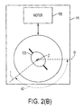
- panning motor 145 is fixedly mounted onto base 111, and is controlled from an external source (not shown) to apply a rotating force that selectively pans (rotates) mirror 135 around optical axis Z to a selected pan angle. As indicated in these figures, the panning operation changes the angle of incident light beams I, which are redirected by mirror 135 along optical axis Z. For example, to move from first pan position A1 shown in Fig. 2 (A) (i.e., approximately 90° from an arbitrarily selected origin O) to second pan position A2 shown in Fig. 2(B) (i.e., approximately 135° from arbitrary origin O), motor 145 is controlled to rotate stage 120 approximately 45°. Note that, in alternative embodiments, panning motor 145 may be mounted on structure other than on base 111.
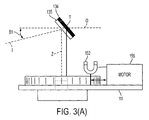
- tilting mechanism 150 selectively changes a magnetic field H applied to magnetic structure 134, whereby magnetic structure 134 selectively pivots around tilt axis T, thereby causing mirror 135 to assume a selected tilt angle B relative to stage 120.
- tilting mechanism 150 includes a permanent magnet 152 that is movable along a track 154 by a linear actuator 155 in order to change (e.g., modulate the strength and/or field gradient) of magnetic field H, as applied to magnetic structure 134.
- mirror 135 and magnetic structure 134 are rotatable (pivotable) around tilt axis T such that modulating the strength and/or field gradient of magnet 152 induces a magnetic torque on magnetic structure 134 that causes rotation of mirror 135 into a desired tilt position.
- motor 155 is fixedly mounted onto base 111, and is controlled from an external source (not shown) to apply a translating force that selectively moves magnet 152 relative to base 111, thereby changing the magnetic torque applied to magnetic structure 134, thus rotating mirror 135 around tilt axis T to a selected tilt angle.
- the tilting operation changes the angle of incident light beams I, which are redirected by mirror 135 relative to an arbitrary horizontal axis O.
- first tilt angle B1 shown in Fig. 3(A) i.e., approximately 30° below arbitrary origin O
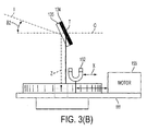
- second tilt angle B2 shown in Fig. 3(B)
- motor 155 is driven to move magnet 152 a predetermined distance X under magnetic structure 134.
- Modeling of tilt mechanism 150 is achieved using techniques known in the art.
- the torque around tilt axis T is produced by the interaction of external magnetic field H exerted by magnet 152 with the induced magnetization of the magnetic structure 134.
- the magnetic structure 134/135 is relatively disk-like in shape, there is a strong amount of shape anisotropy energy which tends to keep the induced magnetization aligned along the surface of the magnetic structure.
- the induced torque results in torsional motion of magnetic structure/mirror 134/135, which is balanced by a mechanical restoring torque provided by frame 132 by way of torsion bar 136.
- a relationship between a position of permanent magnet 152 relative to magnetic structure/mirror 134/135 for a given pan angle A in order to achieve a desired tilt angle T can be determined using known techniques.
- a simple and reasonable first order approximation and estimate can be obtained by (a) assuming the external field M is uniform (b) assuming permanent magnet 152 is strong and close enough to magnetic structure/mirror 134/135 to provide a field strength greater that the coercivity of the magnetic structure/mirror where by the magnetization of the magnetic structure 134/135 can be assumed constant in magnitude, and (c) the mirror is suspended using an equivalent of simple torsion bars.
- the permanent magnet 152 used to induce a magnetization in the magnetic structure 134/135 is composed of a hard ferromagnetic material with a very high residual magnetic field H often referred to as the flux density of a permanent magnet. Examples of such ferromagnetic materials include but are not limited to sintered Samarium Cobalt, sintered Neodymium Iron Boron, or Alnico.
- pan/tilt apparatus 110 facilitates 360° panning by way of pan motor 145 and rotating stage 120, and a very large range of tilt deflection by way of magnet 152, pan motor 155 and magnetic structure 134.
- pan/tilt apparatus 110 exhibits tilt positioning without having to mount tilt motor 155 on rotating stage 120, thereby reducing the weight carried on rotating stage 120, and thus reducing the required size of the pan actuating motor 145.
- tilt actuating motor 145 can be turned off when the desired tilt angle is achieved, producing no static power cost (i.e., all power supplied to pan/tilt apparatus 110 may be turned off once a desired pan/tilt position is achieved).
- Another important benefit of the magnetic actuation is its robustness--that is, tilt actuation achieves using magnetic fields, so no electrostatic fields are applied, and hence there are no stringent requirements on device packaging.
- Fig. 4 is a perspective view showing a pan/tilt apparatus 210 that is designed for a compact pan/tilt unit for miniaturized image capturing devices according to a second embodiment of the present invention.
- pan/tilt apparatus 210 includes base (e.g., a printed circuit board) 211, a rotating stage 220 mounted on base 211, an optical apparatus 230 mounted on stage 220, and a panning mechanism 240 and a tilting mechanism 250 that are both mounted on base 211.
- base e.g., a printed circuit board
- rotating stage 220 mounted on base 211
- optical apparatus 230 mounted on stage 220
- panning mechanism 240 and a tilting mechanism 250 that are both mounted on base 211.
- rotating stage 220 defines a central opening 225, through which light is directed by optical apparatus to an image capturing device (not shown) in the manner described above.
- Rotating stage 220 is rotatably supported on base 211 by way of a low-profile, hollow-shaft bearing spindle 227 which is mounted over a base opening in the manner described above.
- Bearing spindle 227 includes gear teeth 227 disposed around its peripheral edge.
- Such miniature hollow shaft bearing spindles are readily available as low-cost mass produced parts commonly used in portable disk drive applications, or at even cheaper prices from injected molded plastic.
- optical apparatus 230 is mounted on stage 220 and serves to direct light downward through central stage opening 225 to a camera or other image capturing device in the manner described above.
- optical apparatus 230 includes a frame support 231 and a metal frame 232.
- Metal frame 232 which is described in additional detail below, is a substantially flat member having a magnetic structure 234 and a mirror 235 that are connected to side portions of frame 232 by way of torsion bars 236 such that the magnetic structure 234 is pivotable around a tilt (horizontal) axis defined by torsion bars 236 relative to frame 232.
- Magnetic structure 234 (and in some instances mirror 235) are formed using a magnetic material.
- Frame support 231 maintains frame 232 at an approximately 45° angle relative to the upper surface of stage 220, thereby facilitating operation of mirror 235 in a manner similar to that described above with the generalized embodiment.
- frame support 231 and metal frame 232 are mounted inside a transparent container 238 that may be filled with a damping fluid (not shown).
- a damping fluid (not shown).
- transparent container 238 can be filled with a dielectric fluid such as mineral oil or silicone oil. While this damping fluid will lower the resonant frequency of mirror 235, frequency responses above 60 Hz are still adequate because settling times for most pan/tilt systems are on the order of a few seconds.
- Panning mechanism 240 is provided to control a panning angle of mirror 235 relative to base 211 by way of hollow-shaft bearing spindle 227.
- Panning mechanism 240 includes a motor 245 (e.g., miniature stepper motor or pulsed DC brush or brushless motor) having a worm gear 248 that engages gear teeth 229 of spindle 227 such that rotation of worm gear 248 by stepper motor 245 produces a selected amount of rotation of stage 220.
- a motor 245 e.g., miniature stepper motor or pulsed DC brush or brushless motor
- tilting mechanism 250 includes an external hard ferromagnet (permanent) 252 mounted onto the output shaft of a miniature stepper motor 255, which is fixedly mounted to a lower surface of base 211. Tilt actuation is accomplished by driving stepper motor 255 to turn external ferromagnet 252 below base 211.
- the rotation of external ferromagnet 252 causes the angle of magnetic structure 234, which is formed from nickel or a soft ferromagnetic material, to rotate about the tilt axis defined by torsional beams (hinges) 236.
- rotation of magnetic structure 234 causes the surface of mirror 235 to pivot (tilt).
- motor 245 and 255 used for actuating pan and tilt can be shrunk drastically in size as the load these motors need to drive is dramatically reduced in size and weight.
- motor-on-motor geometry as in conventional pan/tilt mechanisms.
- pan motor 245 and hollow-shaft bearing spindle 227 provides a full 360° pan range and tilt motor 255 provides a wide angle of tilt with very little power.
- Pan/tilt apparatus 210 could possibly fit into a inch cube, yet be made from existing very low cost motors used primarily in cameras and a disk drive hollow shaft bearing, thus making pan/tilt apparatus 210 suitable for many current and yet realized miniature high bandwidth low cost pan/tilt camera applications.
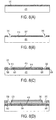
- Figs. 5 (A) to 5(F) show a method for producing a mirror frame 300 similar to that utilized in the specific embodiment described above.
- the process begins with a smooth sheet of a magnetic foil 301 that is in the range of 12-500 microns in thickness ( Fig. 5(A) ).
- foil 301 is then subjected to photochemical etching using known techniques to define the outer frame portions 310 and central mirror portion 320. Photochemical etching can be done simultaneously on both the front and backsides in order to position the torsional hinges along a line passing through the center of mass of the magnetic structure.
- Fig. 5 (A) to 5(F) show a method for producing a mirror frame 300 similar to that utilized in the specific embodiment described above.
- the process begins with a smooth sheet of a magnetic foil 301 that is in the range of 12-500 microns in thickness ( Fig. 5(A) ).
- foil 301 is then subjected to photochemical etching using known techniques to define the outer frame portions 310
- FIG. 5(C) is a top view showing a subsequent laser cutting process that is used to define torsion bars (hinges) 330 between outer frame portions 310 and central mirror portion 320.
- Foil 301 is then optionally subjected to electropolishing ( Fig. 5(D) ) to reduce surface roughness.
- a reflective metal layer is deposited on 330, thereby forming mirror surfaces 335 ( Fig. 5(E) ).
- Highly reflective metal layers are well known in the art and can include thin layers of silver, aluminum, gold, or an alloy thereof as well as a thin adhesion layer (e.g., Chrome) deposited below the reflection layer to enhance the adhesion of the reflective layer to the underlying magnetic structure.
- a thin adhesion layer e.g., Chrome
- foil 301 is then singulated into individual mirror frames (dies) 300 ( Fig. 5(F) ), and cleaned.
- This process provides a cost effective method for producing mirror frames, and ensures a higher volume of magnetization. It is also possible to create such integrated magnetic structures by using electroforming and/or electroplating techniques to build up magnetic films of a patterned thickness.
- the hinges may be made out of a different material other than a magnetic metal in order to increase the range of motion by reducing the modulus of elasticity of the material and eliminating yield deformation at high strains.
- a patterned layer of thin polyimide could be used to form torsional hinges and laminated between two layers of thin magnetic material.
- the magnetic structure with mirror quality surface could be formed on both sides using the same photochemical etching techniques described above.
- Fig. 6 is a picture showing a portion of a pan/tilt apparatus an optical element 430 formed in accordance with an alternative embodiment of the present invention.
- Optical element 430 may be used, for example, in place of optical element 230 in pan/tilt apparatus 210, which is described above with reference to Fig. 4 .
- Optical element 430 utilizes a simple low-cost stressed-metal process to form a frame 432 that lifts a magnetic structure 434 and small mirror 435 attached to the frame 432 via a torsional hinges 436 where a high optical flatness mirror 435 is formed on the opposite side (not shown) behind magnetic structure 434.
- Frame 432 includes several suspension beams that are attached at fixed ends to a glass substrate 431, and magnetic structure/mirror 434/435 are integrally connected to free ends of these beams via torsional hinges 436. As described below, frame 432 is partially released from substrate 431, and internal stresses within the beams lift magnetic structure/mirror 434/435 away from substrate 431. As in the previous embodiments, magnetic structure/mirror 434/435 can then be tilted over a wide angular range by adjusting the position of one or more tiny permanent magnets (not shown) disposed at 1-20 mm distances from magnetic structure/mirror 434/435. Fig. 6 shows magnetic structure/mirror 434/435 lifted almost 45 degrees out of the plane defined by substrate 431.
- the magnetic structure/mirror 434/435 consists of an 8 micron thick Nickel layer formed on top of a thin (1 micron) support layer.
- the suspension beams that form frame 432 have areas on which stressed metal has been deposited according to known techniques. Magnetic structure/mirror 434/435 and portions of the suspension beams are then released from the substrate by removing (etching) a sacrificial amorphous silicon layer using a xenon difluoride release etch.
- magnetic structure 434 is electroplated, it will have a fairly rough top surface which would require addition of a polishing step in the fabrication process to use this surface as mirror surface; however, mirror 435, which his located on the backside of magnetic structure 434, will be optically smooth and can be coated prior to release with a high reflectivity metal such as gold, and hence can be used, for instance, in combination with transparent substrate 431.
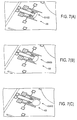
- Figs. 7(A), 7(B) and 7(C) are enlarged photographs (microscope screenshots) of an optical element 430 when a small, disc type, rare earth metal permanent magnet (NdFeB) was brought in the vicinity (a few mm's) of magnetic structure/mirror 434/435 and translated along an axis parallel to the surface of substrate.
- the magnet exerts a force on the soft ferromagnetic nickel layer making up magnetic structure/mirror 434/435, and tends to align the plane of the mirror's body to the magnetic field lines surrounding the magnet.
- Figs. 7(A), 7(B) and 7(C) depict actuation of structure/mirror 434/435 in response to movement of the magnet (not shown).
- FIG. 7(A) shows magnetic structure/mirror 434/435 at a tilt angle of approximately 70°
- Fig. 7(B) shows magnetic structure/mirror 434/435 at a tilt angle of approximately 53°
- Fig. 7(C) shows magnetic structure/mirror 434/435 at a tilt angle of 0° (i.e., pressed against the upper surface of substrate 431).
- Figs. 8(A) to 8(G) depict another process for generating optical element 430 having micromirrors that are possibly better suited for endoscopic and boroscopic applications. Because the thickness of the magnetic structure/mirror 434/435 is limited to thick film photoresist/SU8 and by plating uniformity, this process is most likely limited to small mirrors up to roughly 1.5 mm diameter in size or less.
- the process begins with unannealed glass substrate 431 and includes depositing an a-Si release material layer 510 using known PECVD techniques. As shown in Fig. 8(B) , release material layer 510 is then patterned and dry etched to provide vias (openings) 515 that expose portions of the upper surface of substrate 431. A thin adhesion and mirror layer 517 is deposited. Such a layer could consist of Chrome or Titanium for adhesion and Gold, Aluminum, or Silver for reflection.
- a mask 520 is then patterned over release material layer 510 and Nickel is electroplated through windows in the mask 520.
- the electroplated Nickel is used to form mirror 435, and mask 520 is aligned with openings 515 to facilitate the formation of support beam posts (fixed ends) 530 that extend substantially to the upper surface of substrate 431 (i.e., by way of the adhesion material).
- a support beam mask 540 is then patterned over mirror 435 such that trench-like windows (not shown) are defined that extend from the upper surfaces of support beam post 530 to regions located adjacent to mirror 435 (i.e., in the shape of the support arms forming frame 432 in Fig. 6 ).
- Spring film 550 is then formed in a controlled manner through the trench-like windows formed in support beam mask 540 to form support beams that extend from posts 530 to mirror 435. As indicated in Fig.
- spring film 550 is formed (e.g., sputtered or plated) such that lowermost portions 550L (i.e., the film material located closest to release material layer 510) has a higher internal compressive stress than uppermost portions 550U (i.e., the film material located furthest to release material layer 510), thereby forming internal stress variations in the growth direction (e.g., stress gradient ⁇ +, which increases in the direction perpendicular to the upper surface of substrate 431).
- the thickness of spring film 550 is determined in part by the selected spring material, formation technique, desired spring constant, and shape of the final spring structure.
- stress-engineered spring material film 550 includes one or more metals suitable for forming a spring structure (e.g., one or more of molybdenum (Mo), a "moly-chrome” alloy (MoCr), tungsten (W), a titanium-tungsten alloy (Ti:W), chromium (Cr), nickel (Ni) and a nickel-zirconium alloy (NiZr)).
- Mo molybdenum
- MoCr molybdenum
- MoCr molybdenum
- W molybdenum
- Ti:W titanium-tungsten alloy
- Cr chromium
- NiZr nickel-zirconium alloy
- a spring film 550 (e.g. Ni, Cu, alloys) is deposited onto a seedlayer (e.g. Au, Ni) using electroplating or electroless plating techniques. Similar to the sputtered embodiment described above, in one embodiment the process parameters are changed during plating to generate a suitable stress gradient ⁇ +, although it is possible to form a suitable film without changing the process parameters.
- a plating chemistry is used that deposits at least two elements into the film that can subsequently be transformed to an intermetallic phase using, for example, the annealing processes described herein to bend the resulting spring structure such that its tip is positioned at the target distance away from the underlying substrate surface.
- an Au seed layer is lithographically patterned and then sequentially exposed to an Ni 3 P (first) solution, which forms a relatively compressive lower spring layer portion on the release layer, and then an Ni 3 B (second) solution, which forms a relatively tensile upper spring layer portion on the lower spring layer portion.
- Ni 3 P first
- Ni 3 B second
- Other plated spring types may include Cu with various hardening materials added thereto that are formed using either electroless plating or electroplating. The Cu plating process is performed such that a stress-gradient is formed in the plated material in the plating direction (i.e., similar to that described above for the sputtered embodiments) by, for example, either varying a parameter during the plating process (e.g.
- the plating may be performed using electroplating techniques (i.e., after depositing a suitable seed material (e.g., Au; not shown) onto the upper surface of the release material).
- a suitable seed material e.g., Au; not shown
- release layer 210 must be a conductive material, such as Ti, in order for electroplating to be performed.
- the plated material may be formed as a continuous layer and then etched as described below to form individual spring structures, or individual spring structures may be formed directly by plating through a hard mask.
- the support beam mask and spring material formed thereon are then removed using well-know lift-off techniques, and a thick photoresist magnetic structure mask 560 is patterned over mirror 435 that is used to form magnetic structure 434.
- magnetic structure 434 is formed by electroplating Ni through the opening in mask 560.
- Fig. 8(F) all remaining mask material and portions of the Ti/Au are then removed to expose upper surface portions 512 of a-Si sacrificial release material layer 510 that surround the suspension legs and magnetic structure/mirror 434/435.
- An XeF 2 etchant is then used to remove release material layer 510, thereby partially releasing the suspension legs of frame 432 and magnetic structure/mirror 434/435 from substrate 431, causing the internal stresses within the spring material to lift magnetic structure/mirror 434/435 away from substrate 431 as shown in Fig. 8(G) .
- the substrate 431 may then be diced to form individual optical apparatus 430 before or after the XeF 2 release step.
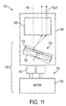
- Fig. 10 is a perspective view showing a portion of an image capturing system 600 for endoscopic applications including a pan/tilt mechanism 610 that utilizes optical apparatus 430 to direct light to and from a GRIN lens 660.
- Substrate 431 of optical apparatus 430 is mounted on a stage 620 that is turned by a panning micromotor 645.
- Tilt operations i.e., deflection of magnetic structure/mirror 434/435
- the light signals are transmitted to and from GRIN lens 660 by an optical bundle 670.
- pan motor 645 and coil 650 are arranged along a very small diameter cylindrical axis. While the field strength of coil 650 will not approach that of a permanent magnet, coil 650 can be placed around the insulating glass GRIN lens or integrally formed by laser etching a helical coil shape onto a metallized GRIN lens. The GRIN lens and coil assembly is place right next to the stressed metal micromirror so as to maximize the strength of the field produced and the stressed metal magnetic micromirror can be made with reduced torsional stiffness due to the tiny mass of magnetic structure/mirror 434/435. The entire pan/tilt apparatus of device 600 requires no difficult non-planar wire bonding, just a single gluing step of micromirror substrate 431 to stage 620, and can fit into a cylinder having a diameter that is less than 2.0 mm.
- the novel non-contact latchable (i.e., no power draw in any hold position) mirror tilting mechanism of the present invention may be utilized independent of the pan/tilt arrangement described above.
- latchable means for maintaining the position of a mirror even when power is shut off is desirable for switching or routing applications, but is very difficult to implement in small form factor devices.
- Figure 11 depicts a simplified optical switching apparatus 700 including an optical system (e.g., a transceiver) 705 and a tilt mechanism 710 in which an input light beam I IN generated by optical transceiver 705 is directed onto an optical apparatus 730 of tilt mechanism 710, and an exit light beam I OUT reflected by optical apparatus 730 is directed back to optical device 705 (or to another optical device).
- optical apparatus 730 includes a magnetic structure 734 and mirror surface 735 that are tiltable around an axis T (shown in end view) and supported by a frame (not shown).
- the tilt angle of mirror 735 determines the location of output beam I OUT , thereby allowing selective switching between, e.g., two or more output fiber optic cables.
- tilting of magnetic structure 734 and mirror surface 735 is achieved by a tilting mechanism 750 which includes a permanent magnet 752 and a motor 755 that is operably disposed to move magnetic 752 in a controllable linear or rotation fashion.
- This non-contact tilting arrangement is highly desirable because it allows optical apparatus 730 to be surrounded or partially surrounded by an enclosure 760 that may be hermetically sealed, whereas motor 755, which often has materials which are incompatible with hermetic sealing, may be situated inside or outside of enclosure 760.
- motor 752 could consist of a compact piezoelectric inchworm device for linear translation of magnet 752, or a precision stepper motor for angular rotation of the polls of magnet 752.
- a low cost small form factor magnetic hall position sensor can be used to provide a feedback signal either inside or outside the enclosure for ensuring precision adjustment of the tilt angle of the magnetic structure.
- Such a non-contact latchable tilting mechanism may be very desirable for fiber optic switching applications with one or more input or output rays of light.
Landscapes
- Engineering & Computer Science (AREA)
- General Engineering & Computer Science (AREA)
- Physics & Mathematics (AREA)
- Mechanical Engineering (AREA)
- General Physics & Mathematics (AREA)
- Optics & Photonics (AREA)
- Multimedia (AREA)
- Signal Processing (AREA)
- Electromagnetism (AREA)
- Mechanical Light Control Or Optical Switches (AREA)
- Accessories Of Cameras (AREA)
- Studio Devices (AREA)
Claims (13)
- Appareil d'inclinaison sans contact pour un système optique, l'appareil comprenant :un appareil optique comportant une structure magnétique (734) qui est soutenue en pivotement pour tourner autour d'un axe d'inclinaison (T), et un élément optique (735) qui est relié fixe à la structure magnétique; etun mécanisme d'inclinaison (750) comportant un aimant permanent (752) et un moyen (755) destiné à positionner l'aimant permanent par rapport à la structure magnétique de façon à ce qu'un changement sélectionné au niveau d'un champ magnétique généré par l'aimant permanent (752) et appliqué à la structure magnétique (734) amène la structure magnétique à tourner autour de l'axe d'inclinaison (T), amenant ainsi l'élément optique (735) à adopter un angle d'inclinaison sélectionné par rapport à l'axe d'inclinaison; l'appareil d'inclinaison caractérisé en ce que ledit moyen de positionnement comprend :un moteur (755) destiné à translater ou à mettre en rotation l'orientation de l'aimant permanent (752) par rapport à la structure magnétique (734) afin d'induire ledit changement dans le champ magnétique appliqué à la structure magnétique.
- Appareil (110) de recadrage/inclinaison pour un système (100) de capture d'images, l'appareil comprenant :une base (111) ;un étage (120) relié en rotation à la base (111) de façon à ce que l'étage puisse tourner autour d'un premier axe (Z) par rapport à la base ;un appareil à inclinaison sans contact pour un système optique selon la revendication 1, dans lequel l'appareil optique (130) est monté sur l'étage et comporte en outre un cadre (132), et où en outrela structure magnétique (734) est reliée au cadre de façon à ce que la structure magnétique puisse tourner autour dudit axe d'inclinaison (T), etl'élément optique (135) comporte un moyen destiné à recevoir une image dirigée le long d'un axe incident, et à rediriger l'image le long du premier axe ;un moyen (140) de recadrage destiné à commander une position de rotation de l'étage (120) par rapport à la base (111), amenant ainsi l'élément optique (136) à adopter un angle de recadrage sélectionné par rapport au premier axe (T) ; etun moyen d'inclinaison (150), dans lequel le moyen d'inclinaison est ledit mécanisme d'inclinaison, destiné à altérer un champ magnétique appliqué à la structure magnétique (734), grâce à quoi un changement sélectionné dans le champ magnétique amène la structure magnétique à tourner autour de l'axe d'inclinaison (T), amenant ainsi l'élément optique (135) à adopter un angle d'inclinaison sélectionné par rapport à l'axe d'inclinaison (T).
- Appareil de recadrage/inclinaison selon la revendication 2, dans lequel le moteur (155) est monté sur la base et est disposé de manière opérationnelle à une position de l'aimant permanent (152) par rapport à la structure magnétique.
- Appareil de recadrage/inclinaison selon la revendication 2 ou 3, dans lequel au moins l'une de la structure magnétique (134) et de l'élément optique (135) comprend un matériau ferromagnétique mou à faible coercivité.
- Appareil de recadrage/inclinaison selon l'une quelconque des revendications 2 à 4, dans lequel au moins l'une de la structure magnétique (134) et de l'élément optique (135) comprend un matériau ferromagnétique dur à coercivité élevée.
- Appareil de recadrage/inclinaison selon l'une quelconque des revendications 2 à 5, dans lequel la structure magnétique (134) et l'élément optique (135) sont reliés au cadre (132) par des faisceaux de torsion (136).
- Appareil de recadrage/inclinaison selon l'une quelconque des revendications 2 à 6, dans lequel le cadre comprend des faisceaux de suspension en porte-à-faux formés par un film-ressort comportant des premières parties de couche ayant une contrainte de compression interne plus élevée que les deuxièmes parties de couche, formant ainsi des variations de contrainte interne.
- Appareil de recadrage/inclinaison selon la revendication 2, dans lequel ledit étage comporte des structures mobiles montées fixes sur celui-ci, et
où le moyen (140) de recadrage comprend un moteur (145) comportant un moyen destiné à engager les structures mobiles. - Appareil de recadrage/inclinaison selon la revendication 8, dans lequel ledit étage comprend une fusée de roulement (127) à arbre creux ayant des dents d'engrenage disposées autour d'un bord périphérique, et
où le moyen (140) de recadrage comprend un moteur (145) comportant un engrenage à vis sans fin engageant les dents d'engrenage. - Appareil de recadrage/inclinaison selon la revendication 8 ou 9, comprenant en outre un récipient transparent monté sur l'étage et contenant l'appareil optique et un fluide d'amortissement.
- Appareil de recadrage/inclinaison selon l'une quelconque des revendications 8 à 10, dans lequel l'étage, l'appareil optique, le moyen de recadrage et le moyen d'inclinaison sont disposés dans une région cylindrique ayant un diamètre inférieur à 5 millimètres.
- Système de capture d'images comprenant :un dispositif (101) de capture d'images ayant un axe optique ; etun système de formation d'images de recadrage/inclinaison selon l'une quelconque des revendications 2 à 11, dans lequel :la base est reliée fixe au dispositif de capture d'images,l'axe optique (Z) définissant ledit premier axe.
- Appareil selon l'une quelconque des revendications précédentes, dans lequel l'élément optique est un miroir.
Applications Claiming Priority (1)
| Application Number | Priority Date | Filing Date | Title |
|---|---|---|---|
| US11/759,184 US8614742B2 (en) | 2007-06-06 | 2007-06-06 | Miniature low cost pan/tilt magnetic actuation for portable and stationary video cameras |
Publications (3)
| Publication Number | Publication Date |
|---|---|
| EP2000733A2 EP2000733A2 (fr) | 2008-12-10 |
| EP2000733A3 EP2000733A3 (fr) | 2009-11-11 |
| EP2000733B1 true EP2000733B1 (fr) | 2011-04-06 |
Family
ID=39712733
Family Applications (1)
| Application Number | Title | Priority Date | Filing Date |
|---|---|---|---|
| EP08157386A Ceased EP2000733B1 (fr) | 2007-06-06 | 2008-06-02 | Actionnement magnétique miniature panoramique horizontal/vertical à bas coût pour caméras vidéo stationnaires et portables |
Country Status (4)
| Country | Link |
|---|---|
| US (1) | US8614742B2 (fr) |
| EP (1) | EP2000733B1 (fr) |
| JP (1) | JP5311884B2 (fr) |
| DE (1) | DE602008005952D1 (fr) |
Families Citing this family (35)
| Publication number | Priority date | Publication date | Assignee | Title |
|---|---|---|---|---|
| CN2909279Y (zh) * | 2006-04-19 | 2007-06-06 | 群康科技(深圳)有限公司 | 角度调整装置及使用该角度调整装置的显示装置检测设备 |
| TWI325038B (en) * | 2006-08-11 | 2010-05-21 | Au Optronics Corp | Variable revolving position device |
| CN101541154B (zh) * | 2008-03-21 | 2012-05-23 | 鸿富锦精密工业(深圳)有限公司 | 旋转装置及使用该旋转装置的电子设备 |
| KR101693562B1 (ko) * | 2009-08-25 | 2017-01-06 | 에이에스엠엘 네델란즈 비.브이. | 광학 장치, 및 반사 요소를 배향하는 방법 |
| KR100978121B1 (ko) * | 2010-04-12 | 2010-08-27 | 주원통신 주식회사 | 감시 카메라 시스템 |
| TWI441513B (zh) * | 2011-02-16 | 2014-06-11 | 影像感測機構 | |
| TWI479168B (zh) * | 2011-06-16 | 2015-04-01 | Hon Hai Prec Ind Co Ltd | 音圈馬達靜態傾角測量裝置 |
| US9450286B1 (en) * | 2012-09-12 | 2016-09-20 | Viasat, Inc. | Systems, devices, and methods for stabilizing an antenna |
| US20170276929A1 (en) * | 2014-09-16 | 2017-09-28 | President And Fellows Of Harvard College | Pop-Up Laminate Structure Including Miniature Optical Components |
| US10015481B2 (en) | 2015-05-05 | 2018-07-03 | Goodrich Corporation | Multi-axis center of mass balancing system for an optical gimbal assembly guided by inertial measurement |
| US10020558B1 (en) | 2015-05-18 | 2018-07-10 | The United States Of America As Represented By The Administrator Of The National Aeronautics And Space Administration | Auto tracking antenna platform |
| US10101457B1 (en) * | 2015-07-15 | 2018-10-16 | Apple Inc. | Mirror tilt actuator |
| US9966825B2 (en) * | 2015-09-18 | 2018-05-08 | Apple Inc. | Haptic actuator including slidably coupled masses including coils and related methods |
| US10283837B2 (en) | 2015-10-23 | 2019-05-07 | Viasat, Inc. | Apparatuses for mounting an antenna assembly |
| LU92924B1 (de) * | 2015-12-23 | 2017-08-07 | Leica Microsystems | Abtastvorrichtung zum Abtasten eines Objekts für den Einsatz in einem Rastermikroskop |
| US10620507B2 (en) | 2016-02-25 | 2020-04-14 | William Conn Lefever | Remote controlled rotating camera mount |
| CN106227240B (zh) * | 2016-07-28 | 2019-06-18 | 纳恩博(北京)科技有限公司 | 一种云台控制方法和装置 |
| WO2018023033A1 (fr) | 2016-07-29 | 2018-02-01 | Western Michigan University Research Foundation | Capteur gyroscopique à base de nanoparticules magnétiques |
| CN106231168B (zh) * | 2016-09-03 | 2019-05-03 | 湖北鑫美企业发展股份有限公司 | 一种多功能摄像机 |
| US10554878B2 (en) * | 2017-03-15 | 2020-02-04 | Pilot, Inc. | Smart selfie mirror |
| CN107249099B (zh) * | 2017-06-12 | 2020-08-11 | 广东工业大学 | 一种探测装置 |
| US10536616B2 (en) | 2017-08-31 | 2020-01-14 | Canon Kabushiki Kaisha | Image pickup apparatus |
| US20190124251A1 (en) * | 2017-10-23 | 2019-04-25 | Sony Corporation | Remotely controllable camera on eyeglass-type mount for the blind |
| GB2568481B (en) * | 2017-11-16 | 2021-09-15 | Motion Impossible Ltd | Support and stabilisation systems |
| CN108613624A (zh) * | 2018-05-24 | 2018-10-02 | 深圳市傲睿智能科技有限公司 | 一种磁敏传感器、伺服系统、贯穿型集成电路模块及磁敏传感器制作工艺 |
| KR102148031B1 (ko) * | 2018-06-25 | 2020-10-14 | 엘지전자 주식회사 | 로봇 |
| US11022778B2 (en) | 2018-08-07 | 2021-06-01 | Goodrich Corporation | Optical system mounts |
| CN111254066B (zh) * | 2018-12-03 | 2023-05-05 | 长春长光华大智造测序设备有限公司 | 一种成像调节装置和高通量基因测序仪 |
| CN109525764B (zh) * | 2018-12-17 | 2020-06-12 | 孙凯宁 | 一种便于调节角度的监控装置 |
| CN109854906B (zh) * | 2018-12-29 | 2024-03-26 | 北京旷视科技有限公司 | 多维度调节机架、图像识别测试系统及对其进行测试方法 |
| KR102743025B1 (ko) | 2019-09-16 | 2024-12-13 | 엘지디스플레이 주식회사 | 디스플레이 고정 장치 |
| CN112004008B (zh) * | 2020-08-25 | 2021-08-20 | 厦门众合天元科技有限公司 | 一种用于监控5g通信设备的监控装置 |
| CN114137719B (zh) * | 2021-12-01 | 2023-03-07 | 南京大学 | 一种偏转可控的纳米线微振镜及其驱动、制备方法 |
| CN116428487B (zh) * | 2023-06-09 | 2023-08-25 | 临沂天瀚电子信息科技有限责任公司 | 一种通信设备安装用的测量装置 |
| CN117502868B (zh) * | 2023-12-06 | 2024-09-27 | 浙江奥年家居有限公司 | 一种基于合金材料的耐磨展具 |
Family Cites Families (21)
| Publication number | Priority date | Publication date | Assignee | Title |
|---|---|---|---|---|
| US3842189A (en) | 1973-01-08 | 1974-10-15 | Rca Corp | Contact array and method of making the same |
| CA1341295C (fr) | 1977-11-29 | 2001-09-25 | Guy Giroux | Circuit de poursuite optique et de pointage dynamique |
| DE3802535A1 (de) * | 1987-05-21 | 1989-02-23 | Sattler Hans Eberhard | Vorrichtung zur betrachtung insbesondere von rohedelsteinen in einer immersionsfluessigkeit |
| EP0671697A1 (fr) | 1993-09-21 | 1995-09-13 | Opticon Sensors Europe B.V. | Générateur de trame de balayage hélicoidale |
| US5613861A (en) | 1995-06-07 | 1997-03-25 | Xerox Corporation | Photolithographically patterned spring contact |
| US6320610B1 (en) * | 1998-12-31 | 2001-11-20 | Sensar, Inc. | Compact imaging device incorporating rotatably mounted cameras |
| US5945898A (en) | 1996-05-31 | 1999-08-31 | The Regents Of The University Of California | Magnetic microactuator |
| US6356308B1 (en) * | 1998-06-11 | 2002-03-12 | Polycom, Inc. | Device for rotatably positioning a camera or similar article about two orthogonal axes |
| JP3489531B2 (ja) * | 1999-06-25 | 2004-01-19 | 日本電気株式会社 | 2軸駆動機構とそれを利用した画像入力装置及び光投射装置 |
| US6483610B1 (en) * | 1999-09-09 | 2002-11-19 | Hewlett-Packard Company | Mounting system for two-dimensional scanner |
| JP2001275096A (ja) | 2000-03-24 | 2001-10-05 | Sony Corp | 撮像および表示装置並びにテレビ会議装置 |
| US6461021B1 (en) * | 2000-09-27 | 2002-10-08 | Wybron, Inc. | Reflector positioning assembly, and associated method, for lighting apparatus |
| US6632373B1 (en) * | 2000-09-28 | 2003-10-14 | Xerox Corporation | Method for an optical switch on a substrate |
| AU2002211426A1 (en) | 2000-10-06 | 2002-04-15 | Idealogix | Multiplexed wireless pan and tilt camera array |
| US6939061B2 (en) * | 2002-01-31 | 2005-09-06 | Alps Electric Co., Ltd. | Turntable device and optical apparatus |
| US6880987B2 (en) * | 2002-06-21 | 2005-04-19 | Quickset International, Inc. | Pan and tilt positioning unit |
| JP4031678B2 (ja) * | 2002-07-08 | 2008-01-09 | 松下電器産業株式会社 | 旋回式カメラ装置 |
| US6715940B2 (en) * | 2002-09-10 | 2004-04-06 | General Electric Company | Rugged miniature pan/tilt dome camera assembly |
| US7071591B2 (en) * | 2003-01-02 | 2006-07-04 | Covi Technologies | Electromagnetic circuit and servo mechanism for articulated cameras |
| KR100612834B1 (ko) | 2003-11-15 | 2006-08-18 | 삼성전자주식회사 | 3차원 위치 측정 센서 |
| JP4262583B2 (ja) | 2003-11-26 | 2009-05-13 | オリンパス株式会社 | 二次元光偏向器 |
-
2007
- 2007-06-06 US US11/759,184 patent/US8614742B2/en not_active Expired - Fee Related
-
2008
- 2008-06-02 EP EP08157386A patent/EP2000733B1/fr not_active Ceased
- 2008-06-02 DE DE602008005952T patent/DE602008005952D1/de active Active
- 2008-06-06 JP JP2008148923A patent/JP5311884B2/ja not_active Expired - Fee Related
Also Published As
| Publication number | Publication date |
|---|---|
| JP2008306727A (ja) | 2008-12-18 |
| JP5311884B2 (ja) | 2013-10-09 |
| US20080303900A1 (en) | 2008-12-11 |
| EP2000733A3 (fr) | 2009-11-11 |
| US8614742B2 (en) | 2013-12-24 |
| EP2000733A2 (fr) | 2008-12-10 |
| DE602008005952D1 (de) | 2011-05-19 |
Similar Documents
| Publication | Publication Date | Title |
|---|---|---|
| EP2000733B1 (fr) | Actionnement magnétique miniature panoramique horizontal/vertical à bas coût pour caméras vidéo stationnaires et portables | |
| US6353492B2 (en) | Method of fabrication of a torsional micro-mechanical mirror system | |
| US5910856A (en) | Integrated hybrid silicon-based micro-reflector | |
| CN101930123B (zh) | 执行机构、光扫描器以及图像形成装置 | |
| JP3552601B2 (ja) | 光偏向子及びこれを用いた表示装置 | |
| US11604347B2 (en) | Force-balanced micromirror with electromagnetic actuation | |
| CN111983801B (zh) | 用于补偿不期望的运动的压电mems致动器及其制造工艺 | |
| US20090185067A1 (en) | Compact automatic focusing camera | |
| US9664899B2 (en) | Optical scanning device and image reading system | |
| CN103282819B (zh) | 可磁驱动的微镜 | |
| WO2017148434A1 (fr) | Dispositif à système microélectromécanique pour positionner un barillet d'objectif | |
| JP3759598B2 (ja) | アクチュエータ | |
| EP1688775A1 (fr) | Miroir progressif et module de caméra équipé de celui-ci | |
| JP2002250886A (ja) | マイクロ光電気機械式レーザスキャナ | |
| JP4642659B2 (ja) | 可変ミラー | |
| US7142743B2 (en) | Latching mechanism for magnetically actuated micro-electro-mechanical devices | |
| US6956683B2 (en) | Pivoting platform having a piezoelectric drive | |
| JP5915100B2 (ja) | ミラーデバイス、ミラーデバイスの製造方法、光スキャナーおよび画像形成装置 | |
| US20240094598A1 (en) | MEMS Image Sensor Assembly | |
| US20230236341A1 (en) | MEMS Deformable Lens Assembly and Process Flow | |
| Sandner et al. | 2d mems vector scanning mirrors for lidar, medical imaging, and high laser power applications | |
| JP4623714B2 (ja) | カメラモジュール及びこのカメラモジュールを用いた携帯端末 | |
| JP5849633B2 (ja) | ミラーデバイス、ミラーデバイスの製造方法、光スキャナーおよび画像形成装置 | |
| JP4623713B2 (ja) | カメラモジュール及びこのカメラモジュールを用いた携帯端末 | |
| JP2006262580A (ja) | 光学的な制御用部材の駆動装置及び撮像装置 |
Legal Events
| Date | Code | Title | Description |
|---|---|---|---|
| PUAI | Public reference made under article 153(3) epc to a published international application that has entered the european phase |
Free format text: ORIGINAL CODE: 0009012 |
|
| AK | Designated contracting states |
Kind code of ref document: A2 Designated state(s): AT BE BG CH CY CZ DE DK EE ES FI FR GB GR HR HU IE IS IT LI LT LU LV MC MT NL NO PL PT RO SE SI SK TR |
|
| AX | Request for extension of the european patent |
Extension state: AL BA MK RS |
|
| PUAL | Search report despatched |
Free format text: ORIGINAL CODE: 0009013 |
|
| AK | Designated contracting states |
Kind code of ref document: A3 Designated state(s): AT BE BG CH CY CZ DE DK EE ES FI FR GB GR HR HU IE IS IT LI LT LU LV MC MT NL NO PL PT RO SE SI SK TR |
|
| AX | Request for extension of the european patent |
Extension state: AL BA MK RS |
|
| 17P | Request for examination filed |
Effective date: 20100511 |
|
| 17Q | First examination report despatched |
Effective date: 20100617 |
|
| AKX | Designation fees paid |
Designated state(s): DE FR GB |
|
| GRAP | Despatch of communication of intention to grant a patent |
Free format text: ORIGINAL CODE: EPIDOSNIGR1 |
|
| GRAS | Grant fee paid |
Free format text: ORIGINAL CODE: EPIDOSNIGR3 |
|
| GRAA | (expected) grant |
Free format text: ORIGINAL CODE: 0009210 |
|
| AK | Designated contracting states |
Kind code of ref document: B1 Designated state(s): DE FR GB |
|
| REG | Reference to a national code |
Ref country code: GB Ref legal event code: FG4D |
|
| REF | Corresponds to: |
Ref document number: 602008005952 Country of ref document: DE Date of ref document: 20110519 Kind code of ref document: P |
|
| REG | Reference to a national code |
Ref country code: DE Ref legal event code: R096 Ref document number: 602008005952 Country of ref document: DE Effective date: 20110519 |
|
| PLBE | No opposition filed within time limit |
Free format text: ORIGINAL CODE: 0009261 |
|
| STAA | Information on the status of an ep patent application or granted ep patent |
Free format text: STATUS: NO OPPOSITION FILED WITHIN TIME LIMIT |
|
| 26N | No opposition filed |
Effective date: 20120110 |
|
| REG | Reference to a national code |
Ref country code: DE Ref legal event code: R097 Ref document number: 602008005952 Country of ref document: DE Effective date: 20120110 |
|
| REG | Reference to a national code |
Ref country code: FR Ref legal event code: PLFP Year of fee payment: 9 |
|
| REG | Reference to a national code |
Ref country code: FR Ref legal event code: PLFP Year of fee payment: 10 |
|
| REG | Reference to a national code |
Ref country code: FR Ref legal event code: PLFP Year of fee payment: 11 |
|
| PGFP | Annual fee paid to national office [announced via postgrant information from national office to epo] |
Ref country code: DE Payment date: 20200519 Year of fee payment: 13 Ref country code: FR Payment date: 20200520 Year of fee payment: 13 |
|
| PGFP | Annual fee paid to national office [announced via postgrant information from national office to epo] |
Ref country code: GB Payment date: 20200525 Year of fee payment: 13 |
|
| REG | Reference to a national code |
Ref country code: DE Ref legal event code: R119 Ref document number: 602008005952 Country of ref document: DE |
|
| GBPC | Gb: european patent ceased through non-payment of renewal fee |
Effective date: 20210602 |
|
| PG25 | Lapsed in a contracting state [announced via postgrant information from national office to epo] |
Ref country code: GB Free format text: LAPSE BECAUSE OF NON-PAYMENT OF DUE FEES Effective date: 20210602 Ref country code: DE Free format text: LAPSE BECAUSE OF NON-PAYMENT OF DUE FEES Effective date: 20220101 |
|
| PG25 | Lapsed in a contracting state [announced via postgrant information from national office to epo] |
Ref country code: FR Free format text: LAPSE BECAUSE OF NON-PAYMENT OF DUE FEES Effective date: 20210630 |