EP2000620A1 - Ausklappbare Struktur - Google Patents
Ausklappbare Struktur Download PDFInfo
- Publication number
- EP2000620A1 EP2000620A1 EP08305232A EP08305232A EP2000620A1 EP 2000620 A1 EP2000620 A1 EP 2000620A1 EP 08305232 A EP08305232 A EP 08305232A EP 08305232 A EP08305232 A EP 08305232A EP 2000620 A1 EP2000620 A1 EP 2000620A1
- Authority
- EP
- European Patent Office
- Prior art keywords
- deployable
- elements
- deployment
- hooking
- blades
- Prior art date
- Legal status (The legal status is an assumption and is not a legal conclusion. Google has not performed a legal analysis and makes no representation as to the accuracy of the status listed.)
- Granted
Links
Images

Classifications
-
- E—FIXED CONSTRUCTIONS
- E06—DOORS, WINDOWS, SHUTTERS, OR ROLLER BLINDS IN GENERAL; LADDERS
- E06B—FIXED OR MOVABLE CLOSURES FOR OPENINGS IN BUILDINGS, VEHICLES, FENCES OR LIKE ENCLOSURES IN GENERAL, e.g. DOORS, WINDOWS, BLINDS, GATES
- E06B3/00—Window sashes, door leaves, or like elements for closing wall or like openings; Layout of fixed or moving closures, e.g. windows in wall or like openings; Features of rigidly-mounted outer frames relating to the mounting of wing frames
- E06B3/92—Doors or windows extensible when set in position
- E06B3/922—Doors or windows extensible when set in position with several wings opening horizontally towards the same side of the opening and each closing a separate part of the opening
-
- E—FIXED CONSTRUCTIONS
- E05—LOCKS; KEYS; WINDOW OR DOOR FITTINGS; SAFES
- E05D—HINGES OR SUSPENSION DEVICES FOR DOORS, WINDOWS OR WINGS
- E05D15/00—Suspension arrangements for wings
- E05D15/06—Suspension arrangements for wings for wings sliding horizontally more or less in their own plane
- E05D15/0604—Suspension arrangements for wings for wings sliding horizontally more or less in their own plane allowing an additional movement
- E05D15/0608—Suspension arrangements for wings for wings sliding horizontally more or less in their own plane allowing an additional movement caused by track lay-out
Definitions
- the invention relates to a deployable structure comprising deployable elements, as well as guide means for folding over these elements, the latter comprising, firstly, first hooking means designed to make them integral with the less in the direction of deployment and secondly second attachment means designed to ensure their connection in their stacked position, at least with respect to a displacement of these deployable elements in a direction corresponding to that stacking.
- the present invention can find application in various fields. However, it finds a particular interest in that of building closure systems such as shutters, doors, or the like.
- a deployable structure as described above comprising blade-shaped elements independent of each other and guiding means comprising, on the one hand, a box adapted to receive these elements in a stacked arrangement and, d on the other hand, a guide that opens into the trunk and is adapted to receive these same elements in a juxtaposed, aligned position.
- these elements comprise mutual hooking means on their edges transverse to their direction of movement in the guide.
- trunk end guide rails in which the lateral ends of the expandable elements, shaped blades, are maintained in their deployed position.
- the trunk As for the trunk, it is delimited by two lateral cheeks, an upper wall and a lower wall, provided with a slot for passage of the blades, a rear wall and a front wall, the latter being located substantially in line with the slot , therefore guide slides of the blades.
- this front wall Exactly, on the inner side, this front wall has a slope allowing a blade entering the trunk during the folding phase to unhook from the next blade to be superimposed on previous blades already stacked in the trunk. Note that the blades stacked in this trunk are pushed against the front wall of the trunk under the impulse of a spring whose function, in the deployment phase, to gradually ensure the attachment of the blades together, during their engagement in the lateral guiding slides.
- this spring pushing the stacked blades towards the front wall of the trunk. Indeed, because of the thickness that can represent the blades in stacked position, this spring must necessarily have a suitable amplitude stroke, which raises the problem of mounting this spring, but also and especially the risk incurred during the disassembly, especially if this disassembly operation is performed by an unsuspecting operator.
- These blades are provided, on their opposite longitudinal edges, hook-shaped elements allowing, once aligned, their interlocking and their connection in the direction of deployment of these blades.
- connecting rods also connect these blades to each other to maintain said blades connected together during folding by stacking said blades and ensure their disengagement during their folding and stacking.
- this rod is pivotally mounted at one of its ends on a first blade, it is also pivotally mounted and sliding on the next blade.
- this sliding end of the rod can move by sliding along the transverse edge of a first blade to allow the superposition, above the latter, of the next blade to which is connected this link in an articulated manner.
- connection between the blades depends on an additional part, in particular a connecting rod, which must be made integral with two successive blades. Because of this rod each of the blades can not be provided individually at the level of the structure of the blind during assembly of the latter. Indeed, the different blades making up the deck must be assembled beforehand others and it is the whole deck that must be installed in one piece.
- this rod still play a role of toggle to unhook the blades relative to each other in the folding phase.
- this rod is brought to cooperate with a roller necessarily implanted judiciously in the box for housing the blades once stacked, this for the purpose, during the folding of the apron in this box, to push the blade coming s' engage in the latter in a direction perpendicular to the plane of the deployment of said deck and unhook the blade relative to the next blade.
- the rod to perform this toggle function, borrows a boomerang shape conferring, in the direction perpendicular to the plane of the deck, a thickness and size which should be taken into account in the dimensioning of the lateral guide slides of this apron.
- attachment of the blades in the direction of deployment of the blind is provided by means quite distinct, in this case by the hooks that equip these blades on their longitudinal edge, even if in the sense of deployment properly said linkage prevents these blades from separating.
- the solution corresponding to the present invention aims to overcome the drawbacks of the state of the art.
- the deployable elements of such a structure although starting from a deployed position in which these deployable elements are juxtaposed in the same plane of alignment, are provided able to stack on top of each other in the folding position, these deployable elements remain, at all times, integral with one of the others, so as to respond effectively to the risk of a stall or rather non-snagging of two successive elements during any deployment maneuver.
- the invention relates to a deployable structure comprising deployable elements, as well as guiding means for ensuring the folding over of these elements, the latter comprising, on the one hand, first attachment means designed able to to make them integral at least in the direction of deployment and secondly second attachment means designed to ensure their connection in their stacked position, at least with respect to a displacement of these deployable elements in a direction corresponding to that of the stack, characterized in that the deployable elements are in the form of end caps, in particular adapted to equip at least one end of a blade of a building closure system, such as a door or the like, the first attachment means consisting, in the front edge of a deployable element, in a male or female fastening element designed adapted to cooperate with a n hooking element, respectively, female or male that comprises in the rear edge the preceding deployable element and the second attachment means comprising a guide slide extending in a direction parallel to the plane of the deployable element in which is able to move a snap hook a deployable element following,
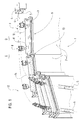
- the present invention relates to a deployable structure 1 which is shown an application in the field of doors, shutters or the like.
- FIG. 1 illustrates such a deployable structure 1 in the form of a sliding door horizontally comprising deployable elements 2 constituted by blades and so called in the following description, this for a better understanding of the invention.
- the present invention is not limited to such an application to closure systems of the building, nor to such a horizontal opening mode.
- the deployable structure may be vertical displacement, just as the deployable elements may be of a different embodiment than that of a blade.
- the deployable elements 2, therefore the blades, are provided to come superimposed on each other, in the folded position of the structure, whereas on the contrary, in the deployed position these blades 2 extend in the same plane of alignment. one against the other.
- guiding means 3 are provided to ensure this superposition of the blades 2 in the folding phase and to bring them in the same extension with respect to each other, during the deployment of the structure 1.
- the guide means are associated at least in part with such a trunk.
- such a box is not essential for housing the blades in the folded position.
- the guide means 3 comprise a guide rail 4 subdivided into two separate channels 5, 6 in which are designed able to come to move separate roller carriages 7, 8 mounted, respectively, near the front edge 10 and rear 11, on the upper end edge 9, a blade 2.
- the guide rail 4 arrived in stacking zone 12 it is possible, at the through channels 5, 6, with a distinct path, of the guide rail 4, to give the blades 2 a trajectory which results, precisely, their stack in a direction substantially perpendicular to the direction of deployment of blades 2.
- these blades 2 comprise first attachment means 13 making them integral, at least in the direction deployment.
- These blades or deployable elements 2 further comprise second attachment means 14 ensuring their connection in their stacked position, at least with respect to a displacement of these blades in a direction corresponding to that of the stack, it is ie transversal to the deployment direction.
- These second hooking means 14 are still means for driving a deployable element 2 with respect to a deployable element 2 preceding and / or following to bring into cooperation their first attachment means during the deployment of the structure.
- a deployable element 2 necessarily drives the deployable element that follows it, that these deployable elements are aligned or stacked. This is also the case during the transitional phases, for example, in the deployment phase, when a deployable element is drawn in alignment with another, which precedes it, by releasing it from the stackable deployable elements that follow, this element deployable carries in its wake the following deployable element so as to bring their respective first attachment means 13 to cooperate with each other.
- these first attachment means 13 consist, in front edge 10 of a deployable element 2, in a male attachment element 15 or female designed capable of cooperating with a respectively female 16 or male hooking element that has the rear edge 11 the previous deployable element 2.
- the male fastening element 15 is defined by a hook extending in a direction substantially perpendicular to the plane of a deployable element 2.
- This hook 15 is designed capable of engaging in a fastening notch 16 forming the female attachment element, as the case of a previous deployable element or a subsequent deployable element.
- the second hooking means 14 consist of a guide slide 17 extending in a direction parallel to the plane of the blade 2, in which is able to move an attachment pin 18 of a deployable element next, according to the previous case, during the relative movements of two successive deployable elements during transient alignment and stacking phases of these deployable elements for deployment or folding.
- this slide 17 and this hooking lug 18 two stackable deployable elements 2, if they are movable relative to each other in the direction of the deployment of the structure, are on the contrary solidary l one of the other in the direction of stacking.
- the slide 17 communicates with a transition track 19 in which engages the hooking lug 18 beyond a relative displacement stroke of two successive deployable elements in the direction of deployment, to bring the hook 15 to engage in the notch 16 of the first attachment means 13 and, thus, fasten these deployable elements 2 for their displacement in the direction of deployment.
- the transition track 19 is advantageously extended by an attachment return 20 to the rear of which engages the hooking lug 18, by tilting, that is to say rotation two successive deployable elements 2 caused by the guide means 3.
- This tilting occurs around the first hooking means 13 through a relative mobility of the hook 15 in the notch 16.
- the snap return 20 ends with a stop 21 limiting not only the tilting of the deployable elements 2, but, in addition, reduces the clearance between two successive deployable elements in the deployed position. This limited game prevents jolts of operation, whether during deployment or refolding.
- the deployable element 2 arriving in the stacking zone 12 firstly flips so as to disengage the latching lug 18 of the latching return 20 to allow then, by pushing the next deployable element, the progression of this hook lug 18 along the transition track 19, resulting in the release of the hook 15 of the notch 16, that is to say the uncoupling of the first hooking means 13.
- the hooking lug 18 continues its movement along the slide 17, again under the effect of the push of the following deployable element 2, whence results the stacking deployable elements 2 otherwise held together in the direction of their stacking.
- the slide 17 is open at its end 22 opposite to the transition track 19 for the release of the latching lug 18, thus the stall and thus the attachment of two deployable elements during the assembly of structure 1 or in case of intervention after sale.
- the deployable elements 2 can be in the form of links, which can be configured in the form of end caps likely to come equip at least one end of a blade.
- these blades will preferably be provided with such endpieces at each of their ends, while guide means 3 will also be arranged on either side of this end. door to keep the blades in a horizontal position.
Landscapes
- Engineering & Computer Science (AREA)
- Mechanical Engineering (AREA)
- Civil Engineering (AREA)
- Structural Engineering (AREA)
- Blinds (AREA)
- Operating, Guiding And Securing Of Roll- Type Closing Members (AREA)
Applications Claiming Priority (1)
| Application Number | Priority Date | Filing Date | Title |
|---|---|---|---|
| FR0755474A FR2917113A1 (fr) | 2007-06-05 | 2007-06-05 | Structure deployable. |
Publications (2)
| Publication Number | Publication Date |
|---|---|
| EP2000620A1 true EP2000620A1 (de) | 2008-12-10 |
| EP2000620B1 EP2000620B1 (de) | 2014-05-07 |
Family
ID=38482685
Family Applications (1)
| Application Number | Title | Priority Date | Filing Date |
|---|---|---|---|
| EP20080305232 Active EP2000620B1 (de) | 2007-06-05 | 2008-06-05 | Ausklappbare Struktur |
Country Status (3)
| Country | Link |
|---|---|
| EP (1) | EP2000620B1 (de) |
| ES (1) | ES2487504T3 (de) |
| FR (1) | FR2917113A1 (de) |
Citations (4)
| Publication number | Priority date | Publication date | Assignee | Title |
|---|---|---|---|---|
| FR2317471A1 (fr) | 1975-06-24 | 1977-02-04 | Hokosho Electric Comm | Dispositif a store |
| FR2414613A1 (fr) | 1978-01-16 | 1979-08-10 | Souchier Georges | Perfectionnements apportes aux systemes d'obturation d'ouvertures, telles que notamment baies, fenetres et similaires |
| US5893403A (en) * | 1994-09-23 | 1999-04-13 | Rolflex Nederland B. V. | Lifting folding door |
| WO2003085229A1 (fr) | 2002-04-08 | 2003-10-16 | Bubendorff Societe Anonyme | Structure deployable |
-
2007
- 2007-06-05 FR FR0755474A patent/FR2917113A1/fr not_active Withdrawn
-
2008
- 2008-06-05 EP EP20080305232 patent/EP2000620B1/de active Active
- 2008-06-05 ES ES08305232.4T patent/ES2487504T3/es active Active
Patent Citations (4)
| Publication number | Priority date | Publication date | Assignee | Title |
|---|---|---|---|---|
| FR2317471A1 (fr) | 1975-06-24 | 1977-02-04 | Hokosho Electric Comm | Dispositif a store |
| FR2414613A1 (fr) | 1978-01-16 | 1979-08-10 | Souchier Georges | Perfectionnements apportes aux systemes d'obturation d'ouvertures, telles que notamment baies, fenetres et similaires |
| US5893403A (en) * | 1994-09-23 | 1999-04-13 | Rolflex Nederland B. V. | Lifting folding door |
| WO2003085229A1 (fr) | 2002-04-08 | 2003-10-16 | Bubendorff Societe Anonyme | Structure deployable |
Also Published As
| Publication number | Publication date |
|---|---|
| FR2917113A1 (fr) | 2008-12-12 |
| ES2487504T3 (es) | 2014-08-21 |
| EP2000620B1 (de) | 2014-05-07 |
Similar Documents
| Publication | Publication Date | Title |
|---|---|---|
| EP0569295A1 (de) | Gepäckträger für Kraftfahrzeuge | |
| EP1922251B1 (de) | Gondelverkleidung für eine strahlturbine und gondel mit mindestens einer derartigen verkleidung | |
| EP4073784A1 (de) | Digitales kakemono | |
| FR2775314A1 (fr) | Verrou automatique pour volet roulant | |
| EP1728962B1 (de) | Vorrichtung zur Befestigung eines Rollladenvorhangs und Rollladen mit einer derartigen Vorrichtung | |
| EP2000620B1 (de) | Ausklappbare Struktur | |
| EP2148040B1 (de) | Behangvorrichtung insbesondere für Verdunkelungssystem und/oder Gebäudeverschlusssystem | |
| EP2146363B1 (de) | Modulares Elektrogerät, das mit einer Etikettenschutzhaube und einer Etikettenzughalterung ausgestattet ist | |
| FR2982313A1 (fr) | Coffre pour volet roulant, avec organes lateraux de guidage formant tulipes | |
| EP0857448B1 (de) | Grillrost aus scharnierartig verbundenen Rostelementen | |
| EP2037078B1 (de) | Automatische Blockiervorrichtung für einen Rollladenvorhang | |
| EP2048320B1 (de) | Rollladen beinhaltend einen Behang für ein Abdecksystem mit verstellbaren Lamellen | |
| FR2459355A1 (fr) | Volet de fenetre a plusieurs panneaux | |
| FR3002249A1 (fr) | Construction comportant une paroi murale comprenant au moins un panneau et un dispositif de maintien de panneau activable/desactivable | |
| EP2832949A1 (de) | Steuerungssystem für die Lamellen von Jalousien, und entsprechende Jalousie | |
| EP2690245B1 (de) | Einlauftrichter und Führungsschiene für Rollladen | |
| EP1593809B1 (de) | Verriegelungsvorrichtung für eine rolladenlamelle und rolladenlamelle mit einer solchen verriegelung | |
| EP1927718B1 (de) | Vorrichtung zur Öffnungsbegrenzung einer Abdeckung und Verschluss- oder Sonnenschutzeinrichtung mit einer solchen Vorrichtung | |
| EP2146044B1 (de) | Panzer einer Verdeckungsvorrichtung, insbesondere eines Rollladens | |
| EP1860619B1 (de) | Pfandschloss für Einkaufswagen | |
| EP1528212B1 (de) | Tür mit versetzter Drehachse | |
| CH661605A5 (fr) | Dispositif consigneur et deconsigneur pour un objet utilitaire, tels qu'un chariot a bagages. | |
| FR2962759A1 (fr) | Volet roulant inclinable automatique | |
| EP1607023A1 (de) | Zusammenklappbarer Tisch, insbesondere für Tischtennis | |
| CH719306B1 (fr) | Fermoir pour bracelet. |
Legal Events
| Date | Code | Title | Description |
|---|---|---|---|
| PUAI | Public reference made under article 153(3) epc to a published international application that has entered the european phase |
Free format text: ORIGINAL CODE: 0009012 |
|
| AK | Designated contracting states |
Kind code of ref document: A1 Designated state(s): AT BE BG CH CY CZ DE DK EE ES FI FR GB GR HR HU IE IS IT LI LT LU LV MC MT NL NO PL PT RO SE SI SK TR |
|
| AX | Request for extension of the european patent |
Extension state: AL BA MK RS |
|
| 17P | Request for examination filed |
Effective date: 20090123 |
|
| AKX | Designation fees paid |
Designated state(s): DE ES FR IT |
|
| GRAP | Despatch of communication of intention to grant a patent |
Free format text: ORIGINAL CODE: EPIDOSNIGR1 |
|
| INTG | Intention to grant announced |
Effective date: 20140226 |
|
| GRAS | Grant fee paid |
Free format text: ORIGINAL CODE: EPIDOSNIGR3 |
|
| GRAA | (expected) grant |
Free format text: ORIGINAL CODE: 0009210 |
|
| RAP1 | Party data changed (applicant data changed or rights of an application transferred) |
Owner name: BUBENDORFF |
|
| AK | Designated contracting states |
Kind code of ref document: B1 Designated state(s): DE ES FR IT |
|
| REG | Reference to a national code |
Ref country code: DE Ref legal event code: R096 Ref document number: 602008032020 Country of ref document: DE Effective date: 20140618 |
|
| REG | Reference to a national code |
Ref country code: ES Ref legal event code: FG2A Ref document number: 2487504 Country of ref document: ES Kind code of ref document: T3 Effective date: 20140821 |
|
| REG | Reference to a national code |
Ref country code: DE Ref legal event code: R097 Ref document number: 602008032020 Country of ref document: DE |
|
| PLBE | No opposition filed within time limit |
Free format text: ORIGINAL CODE: 0009261 |
|
| STAA | Information on the status of an ep patent application or granted ep patent |
Free format text: STATUS: NO OPPOSITION FILED WITHIN TIME LIMIT |
|
| 26N | No opposition filed |
Effective date: 20150210 |
|
| REG | Reference to a national code |
Ref country code: DE Ref legal event code: R097 Ref document number: 602008032020 Country of ref document: DE Effective date: 20150210 |
|
| REG | Reference to a national code |
Ref country code: DE Ref legal event code: R082 Ref document number: 602008032020 Country of ref document: DE Representative=s name: PATENTANWAELTE UND RECHTSANWALT DR. WEISS, ARA, DE Ref country code: DE Ref legal event code: R082 Ref document number: 602008032020 Country of ref document: DE Representative=s name: PATENTANWAELTE UND RECHTSANWALT WEISS, ARAT & , DE |
|
| REG | Reference to a national code |
Ref country code: FR Ref legal event code: PLFP Year of fee payment: 9 |
|
| REG | Reference to a national code |
Ref country code: FR Ref legal event code: PLFP Year of fee payment: 10 |
|
| REG | Reference to a national code |
Ref country code: FR Ref legal event code: PLFP Year of fee payment: 11 |
|
| PGFP | Annual fee paid to national office [announced via postgrant information from national office to epo] |
Ref country code: FR Payment date: 20250317 Year of fee payment: 18 |
|
| PGFP | Annual fee paid to national office [announced via postgrant information from national office to epo] |
Ref country code: DE Payment date: 20250617 Year of fee payment: 18 |
|
| PGFP | Annual fee paid to national office [announced via postgrant information from national office to epo] |
Ref country code: ES Payment date: 20250710 Year of fee payment: 18 |
|
| PGFP | Annual fee paid to national office [announced via postgrant information from national office to epo] |
Ref country code: IT Payment date: 20250606 Year of fee payment: 18 |