EP2000397A1 - Procédé pour la détection de la position angulaire d'une poignée de gaz d'une motocyclette - Google Patents
Procédé pour la détection de la position angulaire d'une poignée de gaz d'une motocyclette Download PDFInfo
- Publication number
- EP2000397A1 EP2000397A1 EP07425345A EP07425345A EP2000397A1 EP 2000397 A1 EP2000397 A1 EP 2000397A1 EP 07425345 A EP07425345 A EP 07425345A EP 07425345 A EP07425345 A EP 07425345A EP 2000397 A1 EP2000397 A1 EP 2000397A1
- Authority
- EP
- European Patent Office
- Prior art keywords
- angular
- rotating shaft
- measurements
- position sensor
- gas knob
- Prior art date
- Legal status (The legal status is an assumption and is not a legal conclusion. Google has not performed a legal analysis and makes no representation as to the accuracy of the status listed.)
- Granted
Links
- 238000000034 method Methods 0.000 title claims abstract description 38
- 238000005259 measurement Methods 0.000 claims abstract description 65
- 238000012545 processing Methods 0.000 claims description 26
- 238000012795 verification Methods 0.000 claims description 12
- 230000000284 resting effect Effects 0.000 claims description 11
- 230000005540 biological transmission Effects 0.000 claims description 9
- 238000009877 rendering Methods 0.000 claims description 2
- 238000004519 manufacturing process Methods 0.000 description 3
- 230000007613 environmental effect Effects 0.000 description 2
- 239000000243 solution Substances 0.000 description 2
- 230000002411 adverse Effects 0.000 description 1
- 239000003795 chemical substances by application Substances 0.000 description 1
- 238000002485 combustion reaction Methods 0.000 description 1
- 238000013461 design Methods 0.000 description 1
- 230000002401 inhibitory effect Effects 0.000 description 1
- 238000012423 maintenance Methods 0.000 description 1
- 239000002184 metal Substances 0.000 description 1
- 238000011084 recovery Methods 0.000 description 1
- 239000012086 standard solution Substances 0.000 description 1
- XLYOFNOQVPJJNP-UHFFFAOYSA-N water Substances O XLYOFNOQVPJJNP-UHFFFAOYSA-N 0.000 description 1
Images

Classifications
-
- B—PERFORMING OPERATIONS; TRANSPORTING
- B62—LAND VEHICLES FOR TRAVELLING OTHERWISE THAN ON RAILS
- B62K—CYCLES; CYCLE FRAMES; CYCLE STEERING DEVICES; RIDER-OPERATED TERMINAL CONTROLS SPECIALLY ADAPTED FOR CYCLES; CYCLE AXLE SUSPENSIONS; CYCLE SIDE-CARS, FORECARS, OR THE LIKE
- B62K11/00—Motorcycles, engine-assisted cycles or motor scooters with one or two wheels
- B62K11/14—Handlebar constructions, or arrangements of controls thereon, specially adapted thereto
-
- F—MECHANICAL ENGINEERING; LIGHTING; HEATING; WEAPONS; BLASTING
- F02—COMBUSTION ENGINES; HOT-GAS OR COMBUSTION-PRODUCT ENGINE PLANTS
- F02D—CONTROLLING COMBUSTION ENGINES
- F02D11/00—Arrangements for, or adaptations to, non-automatic engine control initiation means, e.g. operator initiated
- F02D11/06—Arrangements for, or adaptations to, non-automatic engine control initiation means, e.g. operator initiated characterised by non-mechanical control linkages, e.g. fluid control linkages or by control linkages with power drive or assistance
- F02D11/10—Arrangements for, or adaptations to, non-automatic engine control initiation means, e.g. operator initiated characterised by non-mechanical control linkages, e.g. fluid control linkages or by control linkages with power drive or assistance of the electric type
- F02D11/106—Detection of demand or actuation
-
- F—MECHANICAL ENGINEERING; LIGHTING; HEATING; WEAPONS; BLASTING
- F02—COMBUSTION ENGINES; HOT-GAS OR COMBUSTION-PRODUCT ENGINE PLANTS
- F02D—CONTROLLING COMBUSTION ENGINES
- F02D11/00—Arrangements for, or adaptations to, non-automatic engine control initiation means, e.g. operator initiated
- F02D11/06—Arrangements for, or adaptations to, non-automatic engine control initiation means, e.g. operator initiated characterised by non-mechanical control linkages, e.g. fluid control linkages or by control linkages with power drive or assistance
- F02D11/10—Arrangements for, or adaptations to, non-automatic engine control initiation means, e.g. operator initiated characterised by non-mechanical control linkages, e.g. fluid control linkages or by control linkages with power drive or assistance of the electric type
- F02D11/107—Safety-related aspects
Definitions
- an acquisition system suitable for being used in a motorcycle must be extremely versatile in order to be readily integratable in motorcycles that are even very different from one another in so far as the production of motorcycles is very fragmented and characterized by a vast production of models frequently with small volumes.
- the aim of the present invention is to provide a method for detecting the angular position of a knob for the gas of a motorcycle that will be free from the drawbacks described above and, in particular, easy and inexpensive to produce.
- an method for detecting the angular position of a knob for the gas of a motorcycle is provided according to what is claimed by the annexed claims.
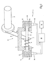
- the reference number 1 designates as a whole an acquisition system for detecting the angular position ⁇ of a gas knob 2 of a motorcycle for a control system of a DBW type.
- the acquisition system 1 comprises a fixed supporting body 3, which is set at a certain distance from the gas knob 2 and is C-shaped.
- a mobile element constituted by a rotating shaft 4, which is mounted idle by means of a pair of bearings 5 so as to be able to turn freely around a central axis of its own.
- the rotating shaft 4 exits from the fixed supporting body 3 at two opposite ends of the rotating shaft 4 itself and is mechanically connected to the gas knob 2 by means of a transmission device 6 that transmits motion from the gas knob 2 to the rotating shaft 4 itself.
- the transmission device 6 is of the cable type and comprises a sheave 7 of a push-pull type, fixed with respect to the rotating shaft 4 and a pair of cables 8 of a Bowden type (i.e., housed in a slidable way within respective external sheaths), each of which has one end constrained to the gas knob 2 and one opposite end, fixed with respect to the sheave 7.
- the sheave 7 is set in a position of centre of the rotating shaft 4 itself and hence is housed in a protected position within the fixed supporting body 3.
- the transmission device 6 is of the cable type and comprises a sheave 7 fixed with respect to the rotating shaft 4 and a single cable 8 of a Bowden type, which has one end constrained to the gas knob 2 and one opposite end fixed with respect to the sheave 7 in such a way that the gas knob 2 is rendered angularly fixed with respect to the rotating shaft 4.
- a return spring 9 set around the rotating shaft 4 for pushing with a given force the rotating shaft 4 itself towards a resting position corresponding to a zero torque.
- each angular-position sensor 10 or 11 has a fixed part or stator 12, fixed with respect to the fixed supporting body 3, and a mobile part or rotor 13, fixed with respect to the rotating shaft 4. Furthermore, each angular-position sensor 10 or 11 is designed to provide two mutually redundant measurements of the angular position ⁇ of the rotating shaft 4; in this way, altogether four mutually redundant measurements of the angular position ⁇ of the rotating shaft 4 are supplied.
- the acquisition system 1 comprises a processing unit 14, which is connected to both of the angular-position sensors 10 and 11 and uses the signals supplied by the angular-position sensors 10 and 11 for determining, with a high degree of certainty the angular position ⁇ of the rotating shaft 4 (i.e., of the gas knob 2).
- the processing unit 14 uses one of the four measurements available for determining the angular position ⁇ of the rotating shaft 4, whilst it uses all four measurements available for verifying proper operation of the angular-position sensors 10 and 11, i.e., for verifying and validating (i.e., confirming) the angular position ⁇ of the rotating shaft 4.
- the processing unit 14 uses the cross comparison between the four measurements available for diagnosing any possible malfunctioning of the angular-position sensors 10 and 11.
- each angular-position sensor 10 or 11 is connected to the processing unit 14 by means of a wiring 15 of its own (comprising connectors and cable) independent of the other angular-position sensor 11 or 10.
- the connectors of the wiring 15 of the angular-position sensor 10 can be physically different (as regards shape and/or dimensions) from the connectors of the wiring 15 of the angular-position sensor 11 in such a way as to prevent the wiring 15 of the two angular-position sensors 10 and 11 from possibly being erroneously reversed during assembly (i.e., reversal of the wiring 15 of the two angular-position sensors 10 and 11 is rendered mechanically impossible).
- the measurements V A and V B of the angular position ⁇ of the rotating shaft 4 of the angular-position sensor 10 increase as the angular position ⁇ of the rotating shaft 4 increases, whilst the measurements V C and V D of the angular position ⁇ of the rotating shaft 4 of the angular-position sensor 11 decrease as the angular position ⁇ of the rotating shaft 4 increases, with a rate of variation equal and opposite to the rate of variation of the measurements V A and V B of the angular position ⁇ of the rotating shaft 4 of the angular-position sensor 10.
- K 1 , K 2 , K 3 and K 4 are verification constants linked to the constructional characteristics of the angular-position sensors 10 and 11, whilst Tolerance 1 and Tolerance 2 are predefined threshold values that take into account the inevitable errors of measurement committed by the angular-position sensors 10 and 11.
- the values of the verification constants K 1 , K 2 , K 3 and K 4 are not established a priori, but are determined during an initial calibration step of the acquisition system 1.
- the acquisition system 1 goes automatically into a calibration or self-learning condition, in which the tester must get the gas knob 2 to make some rotations with the engine turned off.
- the processing unit 14 determines the effective values of the verification constants K 1 , K 2 , K 3 and K 4 that it will use subsequently.
- the acquisition system 1 goes automatically into a calibration or self-learning condition.
- the processing unit 14 measures the effective angular position ⁇ of the rotating shaft 4 (i.e., of the gas knob 2) corresponding to the resting position (i.e., zero torque).
- the tester must not touch the gas knob 2 to enable the processing unit 14 to measure the effective angular position ⁇ of the rotating shaft 4 (i.e., of the gas knob 2) corresponding to the resting position (i.e., zero torque). In this way, it is possible to make up for all the constructional and assembly tolerances and moreover it is possible to verify that the assembly of the acquisition system 1 has been carried out properly.
- the processing unit 14 whenever the ignition key the processing unit 14 is turned, it measures the effective angular position ⁇ of the rotating shaft 4 (i.e., of the gas knob 2) corresponding to the resting position (i.e., zero torque) and inhibits engine ignition until the correctness of said measurement is verified, i.e., the correspondence of said measurement with an expected value.
- the processing unit 14 uses the cross comparison between the four measurements V A , V B , V C and V D available for diagnosing any possible malfunctioning of the angular-position sensors 10 and 11.
- the cross comparison between the four measurements V A , V B , V C and V D available envisages, for example, carrying out the verifications described in the equations [1]-[6] given above. If all the verifications are positive (i.e., if all the equations [1]-[6] are verified within the predefined tolerance margins), then the four measurements available of the angular position ⁇ of the rotating shaft 4 are all correct and equivalent. At this point, the processing unit 14 uses one of these four available measurements of the angular position ⁇ of the rotating shaft 4.
- the processing unit 14 for determining the measurement of the angular position ⁇ of the rotating shaft 4 the processing unit 14 performs an arithmetic mean between the two measurements V A and V B supplied by the main angular-position sensor 10 (if the two angular-position sensors 10 and 11 have different precision), or else performs an arithmetic mean between the four measurements V A , V B , V C and V D supplied by the main angular-position sensors 10 and 11 (if the two angular-position sensors 10 and 11 have the same precision).
- the processing unit 14 identifies the potentiometer or potentiometers that has/have failed of the angular-position sensors 10 and 11 and excludes the measurement (or measurements) V A , V B , V C and V D corresponding to the potentiometer or potentiometers that has/have failed of the angular-position sensors 10 and 11.
- the processing unit 14 determines that the equations [1], [3] and [6] are not verified whilst the equations [2], [4] and [5] are verified. Consequently, if the processing unit 14 determines that the equations [1], [3] and [6] are not verified whilst the equations [2], [4] and [5] are verified, then the processing unit 14 diagnoses a failure of the potentiometer of the angular-position sensor 10 that supplies the measurement V A and in no way uses the measurement V A for determining the angular position ⁇ of the rotating shaft 4 (i.e., of the gas knob 2).
- the processing unit 14 determines that the equations [1], [3]-[6] are not verified whilst only the equation [2] is verified, then the processing unit 14 diagnoses a failure of the angular-position sensor 10 and in no way uses the measurements V A and V B for determining the angular position ⁇ of the rotating shaft 4 (i.e., of the gas knob 2).
- the acquisition method described above enables a precise and above all very reliable measurement of the angular position ⁇ of the rotating shaft 4 (i.e., of the gas knob 2) to be obtained, and even in the event of limited failure of the angular-position sensors 10 and 11 enables travel of the motorcycle in conditions of a high level of safety.
Landscapes
- Engineering & Computer Science (AREA)
- Mechanical Engineering (AREA)
- Chemical & Material Sciences (AREA)
- Combustion & Propulsion (AREA)
- General Engineering & Computer Science (AREA)
- Combined Controls Of Internal Combustion Engines (AREA)
- Control Of Throttle Valves Provided In The Intake System Or In The Exhaust System (AREA)
- Length Measuring Devices With Unspecified Measuring Means (AREA)
Priority Applications (11)
| Application Number | Priority Date | Filing Date | Title |
|---|---|---|---|
| EP07425345A EP2000397B1 (fr) | 2007-06-04 | 2007-06-04 | Procédé pour la détection de la position angulaire d'une poignée de gaz d'une motocyclette |
| DE602007000967T DE602007000967D1 (de) | 2007-06-04 | 2007-06-04 | Verfahren zur Erkennung der Winkelposition eines Gasgriffes eines Motorrads |
| AT07425345T ATE429379T1 (de) | 2007-06-04 | 2007-06-04 | Verfahren zur erkennung der winkelposition eines gasgriffes eines motorrads |
| CN2007800302419A CN101529066B (zh) | 2006-07-07 | 2007-07-06 | 用于设置有气门旋钮和用于检测摩托车的气门旋钮的角位置的采集系统的摩托车的内燃发动机的集成控制系统 |
| PCT/IB2007/001867 WO2008007193A2 (fr) | 2006-07-07 | 2007-07-06 | Système d'acquisition pour détecter la position angulaire d'un bouton des gaz d'une motocyclette |
| US12/309,117 US8046151B2 (en) | 2006-07-07 | 2007-07-06 | Integrated control system for an internal-combustion engine of a motorcycle provided with a gas knob and acquisition system for detecting the angular position of a knob for the gas of a motorcycle |
| EP07804570.5A EP2041413B1 (fr) | 2006-07-07 | 2007-07-06 | Organe de détection de la position angulaire d'une poignée d'accélérateur d'une motocyclette |
| BRPI0713234-4A BRPI0713234B1 (pt) | 2006-07-07 | 2007-07-06 | Sistema de aquisição para detectar a posição angular de um botão para o gás de uma motocicleta |
| US12/018,296 US7729849B2 (en) | 2007-06-04 | 2008-01-23 | Method for detecting the angular position of a knob for the gas of a motorcycle |
| BRPI0800061-1A BRPI0800061A2 (pt) | 2007-06-04 | 2008-01-28 | mÉtodo para detecÇço da posiÇço angular de uma manete para a aceleraÇço de uma motocicleta |
| CN2008100087758A CN101319871B (zh) | 2007-06-04 | 2008-01-29 | 用于检测摩托车的油门旋钮的角位置的方法 |
Applications Claiming Priority (1)
| Application Number | Priority Date | Filing Date | Title |
|---|---|---|---|
| EP07425345A EP2000397B1 (fr) | 2007-06-04 | 2007-06-04 | Procédé pour la détection de la position angulaire d'une poignée de gaz d'une motocyclette |
Publications (2)
| Publication Number | Publication Date |
|---|---|
| EP2000397A1 true EP2000397A1 (fr) | 2008-12-10 |
| EP2000397B1 EP2000397B1 (fr) | 2009-04-22 |
Family
ID=38626246
Family Applications (1)
| Application Number | Title | Priority Date | Filing Date |
|---|---|---|---|
| EP07425345A Not-in-force EP2000397B1 (fr) | 2006-07-07 | 2007-06-04 | Procédé pour la détection de la position angulaire d'une poignée de gaz d'une motocyclette |
Country Status (6)
| Country | Link |
|---|---|
| US (1) | US7729849B2 (fr) |
| EP (1) | EP2000397B1 (fr) |
| CN (1) | CN101319871B (fr) |
| AT (1) | ATE429379T1 (fr) |
| BR (1) | BRPI0800061A2 (fr) |
| DE (1) | DE602007000967D1 (fr) |
Families Citing this family (5)
| Publication number | Priority date | Publication date | Assignee | Title |
|---|---|---|---|---|
| US9528822B2 (en) * | 2013-02-08 | 2016-12-27 | Hunter Engineering Company | Calibration fixture for machine vision vehicle wheel alignment system |
| FR3063043B1 (fr) * | 2017-02-23 | 2019-03-15 | Continental Automotive France | Systeme de commande d'un vehicule muni de commandes electriques |
| CN110869709B (zh) * | 2017-05-12 | 2022-01-21 | 德州仪器公司 | 用以确定电机的可旋转轴的位置的方法及设备 |
| JP7080280B2 (ja) * | 2020-07-27 | 2022-06-03 | 三菱電機株式会社 | 電動制動装置 |
| EP4123264A1 (fr) * | 2021-07-21 | 2023-01-25 | Goodrich Actuation Systems Limited | Dispositif de détection de dépassement de course |
Citations (3)
| Publication number | Priority date | Publication date | Assignee | Title |
|---|---|---|---|---|
| US6089535A (en) * | 1996-12-19 | 2000-07-18 | Toyota Jidosha Kabushiki Kaisha | Throttle valve control device |
| EP1338500A1 (fr) * | 2002-02-26 | 2003-08-27 | Yamaha Hatsudoki Kabushiki Kaisha | Capteur pour la détection de la rotation d'un papillon |
| EP1722085A1 (fr) * | 2005-05-02 | 2006-11-15 | Yamaha Hatsudoki Kabushiki Kaisha | Papillion de gaz électronique |
Family Cites Families (6)
| Publication number | Priority date | Publication date | Assignee | Title |
|---|---|---|---|---|
| US5933005A (en) * | 1997-07-29 | 1999-08-03 | Brunswick Corporation | Throttle position monitor with one stationary sensor and one movable sensor |
| JP2004324720A (ja) * | 2003-04-23 | 2004-11-18 | Aisin Aw Co Ltd | 回転角度検出センサーの故障検出装置 |
| JP4287291B2 (ja) * | 2004-01-06 | 2009-07-01 | ヤマハ発動機株式会社 | 車両のスロットル装置 |
| US7188021B2 (en) * | 2004-10-25 | 2007-03-06 | Litens Automotive Partnership | Angular position sensor-based engine controller system |
| US20070132449A1 (en) * | 2005-12-08 | 2007-06-14 | Madni Asad M | Multi-turn non-contact angular position sensor |
| EP1876339B1 (fr) * | 2006-07-07 | 2010-12-22 | Magneti Marelli S.p.A. | Organe de détection de la position angulaire d'une poignée d'accélérateur d'une motocyclette |
-
2007
- 2007-06-04 DE DE602007000967T patent/DE602007000967D1/de active Active
- 2007-06-04 AT AT07425345T patent/ATE429379T1/de not_active IP Right Cessation
- 2007-06-04 EP EP07425345A patent/EP2000397B1/fr not_active Not-in-force
-
2008
- 2008-01-23 US US12/018,296 patent/US7729849B2/en not_active Expired - Fee Related
- 2008-01-28 BR BRPI0800061-1A patent/BRPI0800061A2/pt not_active IP Right Cessation
- 2008-01-29 CN CN2008100087758A patent/CN101319871B/zh not_active Expired - Fee Related
Patent Citations (3)
| Publication number | Priority date | Publication date | Assignee | Title |
|---|---|---|---|---|
| US6089535A (en) * | 1996-12-19 | 2000-07-18 | Toyota Jidosha Kabushiki Kaisha | Throttle valve control device |
| EP1338500A1 (fr) * | 2002-02-26 | 2003-08-27 | Yamaha Hatsudoki Kabushiki Kaisha | Capteur pour la détection de la rotation d'un papillon |
| EP1722085A1 (fr) * | 2005-05-02 | 2006-11-15 | Yamaha Hatsudoki Kabushiki Kaisha | Papillion de gaz électronique |
Also Published As
| Publication number | Publication date |
|---|---|
| US7729849B2 (en) | 2010-06-01 |
| DE602007000967D1 (de) | 2009-06-04 |
| CN101319871A (zh) | 2008-12-10 |
| ATE429379T1 (de) | 2009-05-15 |
| BRPI0800061A2 (pt) | 2009-01-27 |
| US20080295801A1 (en) | 2008-12-04 |
| EP2000397B1 (fr) | 2009-04-22 |
| CN101319871B (zh) | 2012-08-22 |
Similar Documents
| Publication | Publication Date | Title |
|---|---|---|
| US7571073B2 (en) | Acquisition system for detecting the angular position of a gas twist grip in a motorcycle | |
| US8660746B2 (en) | Accelerator pedal apparatus | |
| US7729849B2 (en) | Method for detecting the angular position of a knob for the gas of a motorcycle | |
| EP0555892B1 (fr) | Système de commande de papillon de moteur | |
| CN110733562B (zh) | 用于控制线控转向系统的设备和方法 | |
| US20090026004A1 (en) | Power steering apparatus having failure detection device for rotation angle sensors | |
| US20100235052A1 (en) | Method Of Determining A Steering Angle In A Motor Vehicle | |
| CN109196208B (zh) | 驱动力控制系统的异常诊断方法以及异常诊断装置 | |
| US6397152B1 (en) | Method and motor control apparatus for the correction of a computer-established torque in the drive train of a motor vehicle | |
| CN104442795A (zh) | 用于对机动车的驱动器进行监控的方法和装置 | |
| US8165736B2 (en) | Control device for watercrafts | |
| CN101749424B (zh) | 建立手动变速器的啮合状态的方法和设备 | |
| EP2041413B1 (fr) | Organe de détection de la position angulaire d'une poignée d'accélérateur d'une motocyclette | |
| JP2009062998A (ja) | 車両制御システム | |
| KR20200072594A (ko) | 크루즈 컨트롤 고장 시 제어방법 및 이를 구현하기 위한 제어로직이 포함된 크루즈 컨트롤 시스템 | |
| JP2005291173A (ja) | 車両制御システム | |
| KR100836296B1 (ko) | 차량의 쉬프트 포지션 센서 고장 처리 방법 | |
| CN114607507B (zh) | 一种发动机的转速检测方法、装置、计算机设备和介质 | |
| JP4609948B2 (ja) | 自動車のアクセルペダルの踏み込み信号発生装置の故障検出方法 | |
| CN2828754Y (zh) | 非接触式汽机车角度传感器 | |
| JP2006228002A (ja) | 故障検知機能付き二重系システム | |
| KR100335930B1 (ko) | 캔 통신에 의한 엔진 토크 표시 방법 | |
| CN120327613A (zh) | 一种基于电机转子位置信号的方向盘转角信号校验方法 | |
| KR100794053B1 (ko) | 파워 스티어링 고장 판단 방법 | |
| KR101229444B1 (ko) | 자동차의 전자제어장치용 가속도 센서 및 휠 가속도 센서의고장진단방법 |
Legal Events
| Date | Code | Title | Description |
|---|---|---|---|
| GRAP | Despatch of communication of intention to grant a patent |
Free format text: ORIGINAL CODE: EPIDOSNIGR1 |
|
| PUAI | Public reference made under article 153(3) epc to a published international application that has entered the european phase |
Free format text: ORIGINAL CODE: 0009012 |
|
| 17P | Request for examination filed |
Effective date: 20080207 |
|
| AK | Designated contracting states |
Kind code of ref document: A1 Designated state(s): AT BE BG CH CY CZ DE DK EE ES FI FR GB GR HU IE IS IT LI LT LU LV MC MT NL PL PT RO SE SI SK TR |
|
| AX | Request for extension of the european patent |
Extension state: AL BA HR MK RS |
|
| GRAS | Grant fee paid |
Free format text: ORIGINAL CODE: EPIDOSNIGR3 |
|
| RAP1 | Party data changed (applicant data changed or rights of an application transferred) |
Owner name: MAGNETI MARELLI HOLDING S.P.A. |
|
| RAP1 | Party data changed (applicant data changed or rights of an application transferred) |
Owner name: MAGNETI MARELLI S.P.A. |
|
| GRAA | (expected) grant |
Free format text: ORIGINAL CODE: 0009210 |
|
| AK | Designated contracting states |
Kind code of ref document: B1 Designated state(s): AT BE BG CH CY CZ DE DK EE ES FI FR GB GR HU IE IS IT LI LT LU LV MC MT NL PL PT RO SE SI SK TR |
|
| REG | Reference to a national code |
Ref country code: GB Ref legal event code: FG4D |
|
| REG | Reference to a national code |
Ref country code: CH Ref legal event code: EP |
|
| REG | Reference to a national code |
Ref country code: IE Ref legal event code: FG4D |
|
| REF | Corresponds to: |
Ref document number: 602007000967 Country of ref document: DE Date of ref document: 20090604 Kind code of ref document: P |
|
| AKX | Designation fees paid |
Designated state(s): AT BE BG CH CY CZ DE DK EE ES FI FR GB GR HU IE IS IT LI LT LU LV MC MT NL PL PT RO SE SI SK TR |
|
| NLV1 | Nl: lapsed or annulled due to failure to fulfill the requirements of art. 29p and 29m of the patents act | ||
| PG25 | Lapsed in a contracting state [announced via postgrant information from national office to epo] |
Ref country code: ES Free format text: LAPSE BECAUSE OF FAILURE TO SUBMIT A TRANSLATION OF THE DESCRIPTION OR TO PAY THE FEE WITHIN THE PRESCRIBED TIME-LIMIT Effective date: 20090802 Ref country code: LT Free format text: LAPSE BECAUSE OF FAILURE TO SUBMIT A TRANSLATION OF THE DESCRIPTION OR TO PAY THE FEE WITHIN THE PRESCRIBED TIME-LIMIT Effective date: 20090422 Ref country code: FI Free format text: LAPSE BECAUSE OF FAILURE TO SUBMIT A TRANSLATION OF THE DESCRIPTION OR TO PAY THE FEE WITHIN THE PRESCRIBED TIME-LIMIT Effective date: 20090422 Ref country code: AT Free format text: LAPSE BECAUSE OF FAILURE TO SUBMIT A TRANSLATION OF THE DESCRIPTION OR TO PAY THE FEE WITHIN THE PRESCRIBED TIME-LIMIT Effective date: 20090422 Ref country code: PT Free format text: LAPSE BECAUSE OF FAILURE TO SUBMIT A TRANSLATION OF THE DESCRIPTION OR TO PAY THE FEE WITHIN THE PRESCRIBED TIME-LIMIT Effective date: 20090822 |
|
| PG25 | Lapsed in a contracting state [announced via postgrant information from national office to epo] |
Ref country code: IS Free format text: LAPSE BECAUSE OF FAILURE TO SUBMIT A TRANSLATION OF THE DESCRIPTION OR TO PAY THE FEE WITHIN THE PRESCRIBED TIME-LIMIT Effective date: 20090822 Ref country code: NL Free format text: LAPSE BECAUSE OF FAILURE TO SUBMIT A TRANSLATION OF THE DESCRIPTION OR TO PAY THE FEE WITHIN THE PRESCRIBED TIME-LIMIT Effective date: 20090422 Ref country code: SI Free format text: LAPSE BECAUSE OF FAILURE TO SUBMIT A TRANSLATION OF THE DESCRIPTION OR TO PAY THE FEE WITHIN THE PRESCRIBED TIME-LIMIT Effective date: 20090422 Ref country code: PL Free format text: LAPSE BECAUSE OF FAILURE TO SUBMIT A TRANSLATION OF THE DESCRIPTION OR TO PAY THE FEE WITHIN THE PRESCRIBED TIME-LIMIT Effective date: 20090422 Ref country code: SE Free format text: LAPSE BECAUSE OF FAILURE TO SUBMIT A TRANSLATION OF THE DESCRIPTION OR TO PAY THE FEE WITHIN THE PRESCRIBED TIME-LIMIT Effective date: 20090722 Ref country code: LV Free format text: LAPSE BECAUSE OF FAILURE TO SUBMIT A TRANSLATION OF THE DESCRIPTION OR TO PAY THE FEE WITHIN THE PRESCRIBED TIME-LIMIT Effective date: 20090422 |
|
| PG25 | Lapsed in a contracting state [announced via postgrant information from national office to epo] |
Ref country code: RO Free format text: LAPSE BECAUSE OF FAILURE TO SUBMIT A TRANSLATION OF THE DESCRIPTION OR TO PAY THE FEE WITHIN THE PRESCRIBED TIME-LIMIT Effective date: 20090422 Ref country code: CZ Free format text: LAPSE BECAUSE OF FAILURE TO SUBMIT A TRANSLATION OF THE DESCRIPTION OR TO PAY THE FEE WITHIN THE PRESCRIBED TIME-LIMIT Effective date: 20090422 Ref country code: DK Free format text: LAPSE BECAUSE OF FAILURE TO SUBMIT A TRANSLATION OF THE DESCRIPTION OR TO PAY THE FEE WITHIN THE PRESCRIBED TIME-LIMIT Effective date: 20090422 Ref country code: MC Free format text: LAPSE BECAUSE OF NON-PAYMENT OF DUE FEES Effective date: 20090630 Ref country code: EE Free format text: LAPSE BECAUSE OF FAILURE TO SUBMIT A TRANSLATION OF THE DESCRIPTION OR TO PAY THE FEE WITHIN THE PRESCRIBED TIME-LIMIT Effective date: 20090422 |
|
| PG25 | Lapsed in a contracting state [announced via postgrant information from national office to epo] |
Ref country code: SK Free format text: LAPSE BECAUSE OF FAILURE TO SUBMIT A TRANSLATION OF THE DESCRIPTION OR TO PAY THE FEE WITHIN THE PRESCRIBED TIME-LIMIT Effective date: 20090422 Ref country code: BE Free format text: LAPSE BECAUSE OF FAILURE TO SUBMIT A TRANSLATION OF THE DESCRIPTION OR TO PAY THE FEE WITHIN THE PRESCRIBED TIME-LIMIT Effective date: 20090422 |
|
| PLBE | No opposition filed within time limit |
Free format text: ORIGINAL CODE: 0009261 |
|
| STAA | Information on the status of an ep patent application or granted ep patent |
Free format text: STATUS: NO OPPOSITION FILED WITHIN TIME LIMIT |
|
| 26N | No opposition filed |
Effective date: 20100125 |
|
| PG25 | Lapsed in a contracting state [announced via postgrant information from national office to epo] |
Ref country code: BG Free format text: LAPSE BECAUSE OF FAILURE TO SUBMIT A TRANSLATION OF THE DESCRIPTION OR TO PAY THE FEE WITHIN THE PRESCRIBED TIME-LIMIT Effective date: 20090722 |
|
| REG | Reference to a national code |
Ref country code: IE Ref legal event code: MM4A |
|
| PG25 | Lapsed in a contracting state [announced via postgrant information from national office to epo] |
Ref country code: IE Free format text: LAPSE BECAUSE OF NON-PAYMENT OF DUE FEES Effective date: 20090604 |
|
| PG25 | Lapsed in a contracting state [announced via postgrant information from national office to epo] |
Ref country code: GR Free format text: LAPSE BECAUSE OF FAILURE TO SUBMIT A TRANSLATION OF THE DESCRIPTION OR TO PAY THE FEE WITHIN THE PRESCRIBED TIME-LIMIT Effective date: 20090723 |
|
| PG25 | Lapsed in a contracting state [announced via postgrant information from national office to epo] |
Ref country code: LU Free format text: LAPSE BECAUSE OF NON-PAYMENT OF DUE FEES Effective date: 20090604 Ref country code: MT Free format text: LAPSE BECAUSE OF FAILURE TO SUBMIT A TRANSLATION OF THE DESCRIPTION OR TO PAY THE FEE WITHIN THE PRESCRIBED TIME-LIMIT Effective date: 20090422 |
|
| PG25 | Lapsed in a contracting state [announced via postgrant information from national office to epo] |
Ref country code: HU Free format text: LAPSE BECAUSE OF FAILURE TO SUBMIT A TRANSLATION OF THE DESCRIPTION OR TO PAY THE FEE WITHIN THE PRESCRIBED TIME-LIMIT Effective date: 20091023 |
|
| PG25 | Lapsed in a contracting state [announced via postgrant information from national office to epo] |
Ref country code: TR Free format text: LAPSE BECAUSE OF FAILURE TO SUBMIT A TRANSLATION OF THE DESCRIPTION OR TO PAY THE FEE WITHIN THE PRESCRIBED TIME-LIMIT Effective date: 20090422 |
|
| PG25 | Lapsed in a contracting state [announced via postgrant information from national office to epo] |
Ref country code: CY Free format text: LAPSE BECAUSE OF FAILURE TO SUBMIT A TRANSLATION OF THE DESCRIPTION OR TO PAY THE FEE WITHIN THE PRESCRIBED TIME-LIMIT Effective date: 20090422 |
|
| REG | Reference to a national code |
Ref country code: CH Ref legal event code: PL |
|
| GBPC | Gb: european patent ceased through non-payment of renewal fee |
Effective date: 20110604 |
|
| PG25 | Lapsed in a contracting state [announced via postgrant information from national office to epo] |
Ref country code: CH Free format text: LAPSE BECAUSE OF NON-PAYMENT OF DUE FEES Effective date: 20110630 Ref country code: LI Free format text: LAPSE BECAUSE OF NON-PAYMENT OF DUE FEES Effective date: 20110630 |
|
| PG25 | Lapsed in a contracting state [announced via postgrant information from national office to epo] |
Ref country code: GB Free format text: LAPSE BECAUSE OF NON-PAYMENT OF DUE FEES Effective date: 20110604 |
|
| REG | Reference to a national code |
Ref country code: FR Ref legal event code: PLFP Year of fee payment: 9 |
|
| PGFP | Annual fee paid to national office [announced via postgrant information from national office to epo] |
Ref country code: DE Payment date: 20150521 Year of fee payment: 9 |
|
| PGFP | Annual fee paid to national office [announced via postgrant information from national office to epo] |
Ref country code: IT Payment date: 20150529 Year of fee payment: 9 Ref country code: FR Payment date: 20150526 Year of fee payment: 9 |
|
| REG | Reference to a national code |
Ref country code: DE Ref legal event code: R119 Ref document number: 602007000967 Country of ref document: DE |
|
| REG | Reference to a national code |
Ref country code: FR Ref legal event code: ST Effective date: 20170228 |
|
| PG25 | Lapsed in a contracting state [announced via postgrant information from national office to epo] |
Ref country code: FR Free format text: LAPSE BECAUSE OF NON-PAYMENT OF DUE FEES Effective date: 20160630 Ref country code: DE Free format text: LAPSE BECAUSE OF NON-PAYMENT OF DUE FEES Effective date: 20170103 |
|
| PG25 | Lapsed in a contracting state [announced via postgrant information from national office to epo] |
Ref country code: IT Free format text: LAPSE BECAUSE OF NON-PAYMENT OF DUE FEES Effective date: 20160604 |