EP2000365A1 - Stop part for the ceiling trim assembly of an automobile vehicle roof - Google Patents
Stop part for the ceiling trim assembly of an automobile vehicle roof Download PDFInfo
- Publication number
- EP2000365A1 EP2000365A1 EP08300217A EP08300217A EP2000365A1 EP 2000365 A1 EP2000365 A1 EP 2000365A1 EP 08300217 A EP08300217 A EP 08300217A EP 08300217 A EP08300217 A EP 08300217A EP 2000365 A1 EP2000365 A1 EP 2000365A1
- Authority
- EP
- European Patent Office
- Prior art keywords
- piece
- roof
- trim
- abutment
- assembly according
- Prior art date
- Legal status (The legal status is an assumption and is not a legal conclusion. Google has not performed a legal analysis and makes no representation as to the accuracy of the status listed.)
- Granted
Links
Images

Classifications
-
- B—PERFORMING OPERATIONS; TRANSPORTING
- B60—VEHICLES IN GENERAL
- B60R—VEHICLES, VEHICLE FITTINGS, OR VEHICLE PARTS, NOT OTHERWISE PROVIDED FOR
- B60R13/00—Elements for body-finishing, identifying, or decorating; Arrangements or adaptations for advertising purposes
- B60R13/04—External Ornamental or guard strips; Ornamental inscriptive devices thereon
-
- B—PERFORMING OPERATIONS; TRANSPORTING
- B60—VEHICLES IN GENERAL
- B60R—VEHICLES, VEHICLE FITTINGS, OR VEHICLE PARTS, NOT OTHERWISE PROVIDED FOR
- B60R13/00—Elements for body-finishing, identifying, or decorating; Arrangements or adaptations for advertising purposes
- B60R13/06—Sealing strips
-
- B—PERFORMING OPERATIONS; TRANSPORTING
- B60—VEHICLES IN GENERAL
- B60R—VEHICLES, VEHICLE FITTINGS, OR VEHICLE PARTS, NOT OTHERWISE PROVIDED FOR
- B60R13/00—Elements for body-finishing, identifying, or decorating; Arrangements or adaptations for advertising purposes
- B60R13/07—Water drainage or guide means not integral with roof structure
Definitions
- the invention relates to a roof trim wheel of a motor vehicle.
- the body In a motor vehicle, the body generally comprises a roof piece extending on the top of the passenger compartment and body side parts extending on the lateral sides of the vehicle. Each side body part is disposed on one side of the roof piece and is intended to receive a door.
- the roof piece and a body side part are fixed to each other, generally by welding, forming a groove between them.
- the groove thus formed extends along a lateral edge of the vehicle roof from the windshield frame to the rear window frame of the vehicle.
- the groove is adapted to receive a roof trim to hide the junction between the roof piece and the side part of the body.
- Each roof trim generally comprises a facing piece (for example of aluminum or plastic) intended to be visible, and a piece of gasket (for example rubber) forming lips intended to be inserted into the groove to maintain the hubcap in the throat.
- a facing piece for example of aluminum or plastic
- a piece of gasket for example rubber
- this technique does not control the games between the hubcap, the roof liner and the windshield part that supports the windshield.
- An object of the invention is to allow a more precise longitudinal positioning of a roof cap hubcap during assembly operations of the vehicle body.
- a roof trim assembly of a motor vehicle comprising a hubcap adapted to be inserted into a groove formed between a roof slab part and a side piece of crate for concealing a junction between the roof lining piece and the body side part, characterized in that it further comprises a stop piece adapted to bear against the roof liner piece to position the hubcap relative to the roof liner piece in a longitudinal direction of the vehicle.
- the roof cap trim can be positioned precisely relative to the vehicle.
- the invention further relates to an abutment piece for a roof cap assembly of a motor vehicle roof according to the above definition.
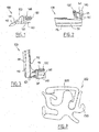
- the abutment piece 100 shown is intended to be arranged at a front left corner of a roof of a vehicle.
- a symmetrical part not shown is intended to be arranged in the same way at a right front corner of the vehicle.
- the stop piece 100 comprises a first portion 110, a second portion 120, a third portion 130 and a fourth portion 140.
- the first portion 110 includes a first surface 111 facing forward and a cut 112 at the rear.
- the first surface 111 has an elongated and concave shape. This surface is intended to receive in support a windshield trim of the vehicle to position the windshield trim relative to the roof flag.
- the cutout 112 has a curved shape adapted to conform to the shape of a corner of a roof pavilion. This cutout is intended to bear against a corner of the roof flag to position the stop piece 100 relative to the flag in longitudinal and transverse directions of the vehicle.
- the second portion 120 comprises fins 121 each having a slice of generally curved shape adapted to conform to the shape of an end surface of a roof trim hubcap.
- the slices of the fins are intended to receive in support of an end surface of a roof cap trim to position the hubcap relative to the roof piece in a longitudinal direction of the vehicle.
- the third portion 130 comprises a pin 131 having protruding conical reliefs oriented to form a non-return means.
- the pin 131 is intended to be inserted in a longitudinal direction of a groove of a joint piece of the roof cap trim to fix the stop piece 100 on the roof trim hubcap.
- the fourth portion 140 includes tabs 141 intended to be inserted on either side of the lip of the roof cap trim piece to index the position of the hubcap relative to the abutment piece. 100.
- the workpiece is integrally formed by plastic injection molding.
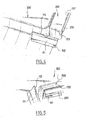
- a stop piece 1 00 and a roof cap trim 200 have been set up on a roof plate 300 of a vehicle.
- the abutment piece 100 is immobilized relative to the roof flag thanks to the cutout 112 which bears against a corner of the roof.
- the surface 111 for receiving the windshield trim is oriented towards the front of the vehicle.
- the roof cap trim 200 comprises a facing piece 220 and a seal 230.
- the facing piece 220 has a front end 221 curved downwards.
- the curved end 221 is held in abutment on the abutment piece 100 (more precisely, it is held in abutment on the fins of the abutment piece which do not appear on the Figures 4 and 5 ).
- the second portion 120 of the abutment piece is interposed between the curved end 221 of the facing piece 220 and the seal 230 of the roof cap trim.
- the pin and legs of the pieces 100 engage the seal to hold the workpiece and the seal fixed to one another.
- a windshield trim 400 was mounted on the vehicle body.
- the windshield trim 400 is immobilized in abutment against the surface 111 of the abutment piece 100.
- the figure 8 represents a cross section of a roof cap hubcap 200.
- the roof cap trim 200 comprises a facing piece 220 and a joint piece 230.
- the facing piece 220 has a generally V-shaped cross section with two lips.
- the seal member 230 having a star cross-section comprises a plurality of lips and grooves extending between the lips.
- the facing piece 220 is held on the seal piece 230 by inserting a lip of the facing piece into a groove of the joint piece.
- the seal piece is adapted to be inserted into a groove formed between the roof piece and the vehicle body side part, so that the roof cap trim 200 masks the junction between the roof piece and the piece. side of the box.
- the stop piece 100 shown on the Figures 1 to 3 is suitable for being fixed on the seal piece 230 with the pin 131 and the tabs 141.
- the pin 131 is inserted in a longitudinal direction of the seal piece 230 between two lips thereof.
- the lugs 141 come to grip a lip of the joint piece 230 to index the joint piece 230 with respect to the facing piece 220.
Landscapes
- Engineering & Computer Science (AREA)
- Mechanical Engineering (AREA)
- Vehicle Interior And Exterior Ornaments, Soundproofing, And Insulation (AREA)
- Seal Device For Vehicle (AREA)
Abstract
Description
L'invention concerne un enjoliveur de pavillon de toit de véhicule automobile.The invention relates to a roof trim wheel of a motor vehicle.
Dans un véhicule automobile, la caisse comporte généralement une pièce de pavillon s'étendant sur le dessus de l'habitacle et des pièces de côté de caisse s'étendant sur les flancs latéraux du véhicule. Chaque pièce de côté de caisse est disposée d'un côté de la pièce de pavillon et est destinée à recevoir une portière.In a motor vehicle, the body generally comprises a roof piece extending on the top of the passenger compartment and body side parts extending on the lateral sides of the vehicle. Each side body part is disposed on one side of the roof piece and is intended to receive a door.
La pièce de pavillon et une pièce de côté de caisse sont fixées l'une à l'autre, généralement par soudage, en formant entre elles une gorge. La gorge ainsi formée s'étend le long d'un bord latéral du toit du véhicule depuis l'encadrement de pare-brise jusqu'à l'encadrement de lunette arrière du véhicule. La gorge est apte à recevoir un enjoliveur de pavillon pour masquer la jonction entre la pièce de pavillon et la pièce de côté de caisse.The roof piece and a body side part are fixed to each other, generally by welding, forming a groove between them. The groove thus formed extends along a lateral edge of the vehicle roof from the windshield frame to the rear window frame of the vehicle. The groove is adapted to receive a roof trim to hide the junction between the roof piece and the side part of the body.
Chaque enjoliveur de pavillon comprend généralement une pièce de parement (par exemple en aluminium ou en matière plastique) destinée à être visible, et une pièce de joint (par exemple en caoutchouc) formant des lèvres destinées à être insérées dans la gorge pour maintenir l'enjoliveur dans la gorge.Each roof trim generally comprises a facing piece (for example of aluminum or plastic) intended to be visible, and a piece of gasket (for example rubber) forming lips intended to be inserted into the groove to maintain the hubcap in the throat.
Au cours des opérations de montage de la caisse, un opérateur vient insérer en force l'enjoliveur de pavillon dans la gorge. Le contrôle du positionnement de l'enjoliveur dans la direction longitudinale de la caisse est alors réalisé par l'opérateur de manière visuelle.During the assembly operations of the body, an operator comes to force insert the hubcap in the groove. The control of the positioning of the trim in the longitudinal direction of the body is then performed by the operator visually.
Cependant, cette technique ne permet pas d'obtenir un positionnement reproductible de l'enjoliveur de pavillon.However, this technique does not provide a reproducible positioning of the hubcap.
En particulier, cette technique ne permet pas de maîtriser les jeux entre l'enjoliveur, le pavillon de toit et la pièce de pare-brise qui supporte le pare-brise.In particular, this technique does not control the games between the hubcap, the roof liner and the windshield part that supports the windshield.
Un but de l'invention est de permettre un positionnement longitudinal plus précis d'un enjoliveur de pavillon de toit lors des opérations de montage de la caisse du véhicule.An object of the invention is to allow a more precise longitudinal positioning of a roof cap hubcap during assembly operations of the vehicle body.
Ce problème est résolu dans le cadre de la présente invention grâce à un ensemble d'enjoliveur de pavillon de toit de véhicule automobile, comprenant un enjoliveur adapté pour être inséré dans une gorge ménagée entre une pièce de pavillon de toit et une pièce de côté de caisse pour masquer une jonction entre la pièce de pavillon de toit et la pièce de côté de caisse, caractérisé en ce qu'il comprend en outre une pièce de butée apte à venir en appui sur la pièce de pavillon de toit pour positionner l'enjoliveur par rapport à la pièce de pavillon de toit selon une direction longitudinale du véhicule.This problem is solved in the context of the present invention by means of a roof trim assembly of a motor vehicle, comprising a hubcap adapted to be inserted into a groove formed between a roof slab part and a side piece of crate for concealing a junction between the roof lining piece and the body side part, characterized in that it further comprises a stop piece adapted to bear against the roof liner piece to position the hubcap relative to the roof liner piece in a longitudinal direction of the vehicle.
Grâce à la pièce de butée, l'enjoliveur de pavillon de toit peut être positionné de manière précise par rapport au véhicule.Thanks to the stop piece, the roof cap trim can be positioned precisely relative to the vehicle.
L'ensemble peut en outre présenter les caractéristiques suivantes
- la pièce de butée comprend une découpe présentant une forme complémentaire d'un coin de la pièce de pavillon de toit, la découpe étant apte à venir en appui contre un coin de la pièce de pavillon de toit pour immobiliser la pièce de butée selon des directions longitudinale et transversale du véhicule,
- la pièce de butée comprend au moins une ailette présentant une tranche de forme générale courbe apte à épouser la forme d'une partie d'extrémité d'une pièce de parement de l'enjoliveur de pavillon de toit pour positionner la pièce de parement selon une direction longitudinale du véhicule,
- la pièce de butée comprend des moyens de fixation de la pièce de butée à une pièce de joint de l'enjoliveur de pavillon de toit,
- les moyens de fixation comprennent un pion apte à être inséré dans une gorge d'une pièce de joint de l'enjoliveur de de toit,
- la pièce de butée comprend des moyens d'indexage de la pièce de butée par rapport à une pièce de joint de l'enjoliveur de pavillon de toit,
- la pièce de butée comprend une surface d'appui adaptée pour recevoir un enjoliveur de pare-brise,
- the abutment piece comprises a cutout having a shape complementary to a corner of the roof pane piece, the cutout being able to abut against a corner of the roof pane piece to immobilize the abutment piece in directions longitudinal and transverse of the vehicle,
- the abutment piece comprises at least one fin having a slice of generally curved shape adapted to conform to the shape of an end portion of a facing piece of the roof cap trim to position the facing piece according to a longitudinal direction of the vehicle,
- the abutment piece comprises means for fastening the abutment piece to a joint part of the roof cap hubcap,
- the fixing means comprise a pin capable of being inserted into a groove of a piece of joint of the roof trim,
- the abutment piece comprises means for indexing the abutment piece with respect to a piece of joint of the roof pane hubcap,
- the abutment piece comprises a bearing surface adapted to receive a windshield trim,
L'invention se rapporte en outre à une pièce de butée pour un ensemble d'enjoliveur de pavillon de toit de véhicule automobile conforme à la définition qui précède.The invention further relates to an abutment piece for a roof cap assembly of a motor vehicle roof according to the above definition.
D'autres caractéristiques et avantages ressortiront encore de la description qui suit, laquelle est purement illustrative et non limitative et doit être lue en regard des dessins annexés, parmi lesquels :
- les
figures 1 à 3 représentent de manière schématique une pièce de butée pour enjoliveur de pavillon de toit, conforme à un mode de réalisation de l'invention, respectivement en vue de côté, en vue de face et en vue de dessus, - les
figures 4 et 5 représentent de manière schématique, en perspective, un enjoliveur de pavillon de toit muni de la pièce de butée lorsqu'ils sont mis en place sur la caisse du véhicule, avant assemblage d'un enjoliveur de pare-brise, - les
figures 6 et 7 représentent de manière schématique, un enjoliveur de pavillon de toit muni de la pièce de butée lorsqu'ils sont mis en place sur la caisse du véhicule, après assemblage d'un enjoliveur de pare-brise, respectivement en perspective et en coupe, - la
figure 8 représente une section d'un enjoliveur de pavillon de toit.
- the
Figures 1 to 3 schematically represent an abutment piece for roof cap trim, according to an embodiment of the invention, respectively in side view, in front view and in plan view, - the
Figures 4 and 5 schematically represent, in perspective, a roof cap trim with the abutment piece when they are placed on the vehicle body, before assembly of a windshield trim, - the
Figures 6 and 7 show schematically, a roof cap trim with the stop piece when they are placed on the vehicle body, after assembly of a windshield trim, respectively in perspective and in section, - the
figure 8 represents a section of a roof pavilion hubcap.
Sur les
La pièce de butée 100 comprend une première partie 110, une deuxième partie 120, une troisième partie 130 et une quatrième partie 140.The
La première partie 110 comprend une première surface 111 orientée vers l'avant et une découpe 112 à l'arrière.The
La première surface 111 présente une forme allongée et concave. Cette surface est destinée à recevoir en appui un enjoliveur de pare-brise du véhicule pour positionner l'enjoliveur de pare-brise par rapport au pavillon de toit.The
La découpe 112 présente une forme courbe apte à épouser la forme d'un coin d'un pavillon de toit. Cette découpe est destinée à venir en appui contre un coin du pavillon de toit pour positionner la pièce de butée 100 par rapport au pavillon selon des directions longitudinale et transversale du véhicule.The
La deuxième partie 120 comprend des ailettes 121 présentant chacune une tranche de forme générale courbe apte à épouser la forme d'une surface d'extrémité d'un enjoliveur de pavillon de toit. Les tranches des ailettes sont destinées à recevoir en appui d'une surface d'extrémité d'un enjoliveur de pavillon de toit pour positionner l'enjoliveur par rapport à la pièce de pavillon selon une direction longitudinale du véhicule.The
La troisième partie 130 comprend un pion 131 présentant des reliefs coniques en saillie orientés pour former des moyens anti-retour. Le pion 131 est destiné à être inséré dans une direction longitudinale d'une gorge d'une pièce de joint de l'enjoliveur de pavillon de toit pour fixer la pièce de butée 100 sur l'enjoliveur de pavillon de toit.The
Enfin, la quatrième partie 140 comprend des pattes 141 destinées à être insérées de part et d'autre de lèvres de la pièce de joint de l'enjoliveur de pavillon de toit pour indexer la position de l'enjoliveur par rapport à la pièce de butée 100.Finally, the
La pièce est formée d'un seul tenant par moulage par injection de matière plastique.The workpiece is integrally formed by plastic injection molding.
Sur les
La pièce de butée 100 est immobilisée par rapport au pavillon de toit grâce à la découpe 112 qui vient en appui contre un coin du pavillon.The
Dans cette position, la surface 111 destinée à recevoir l'enjoliveur de pare-brise est orientée vers l'avant du véhicule.In this position, the
L'enjoliveur de pavillon de toit 200 comprend une pièce de parement 220 et un joint 230. La pièce de parement 220 présente une extrémité avant 221 courbée vers le bas. L'extrémité courbée 221 est maintenue en appui sur la pièce de butée 100 (plus précisément, elle est maintenue en appui sur les ailettes de la pièce de butée qui n'apparaissent pas sur les
La deuxième partie 120 de la pièce de butée est interposée entre l'extrémité courbée 221 de la pièce de parement 220 et le joint 230 de l'enjoliveur de pavillon de toit.The
Le pion et les pattes de la pièces 100 sont en prise avec le joint pour maintenir la pièce et le joint fixés l'un sur l'autre.The pin and legs of the
Sur les
La
L'enjoliveur de pavillon de toit 200 comprend une pièce de parement 220 et une pièce de joint 230.The
La pièce de parement 220 présente une section transversale en forme générale de V présentant deux lèvres.The facing
La pièce de joint 230 présentant une section transversale en étoile comprenant une pluralité de lèvres et de gorges s'étendant entre les lèvres.The
La pièce de parement 220 est maintenue sur la pièce de joint 230 par insertion d'une lèvre de la pièce de parement dans une gorge de la pièce de joint.The facing
La pièce de joint est apte à être insérée dans une gorge formée entre la pièce de pavillon et la pièce de côté de caisse du véhicule, de sorte que l'enjoliveur de pavillon de toit 200 masque la jonction entre la pièce de pavillon et la pièce de côté de caisse.The seal piece is adapted to be inserted into a groove formed between the roof piece and the vehicle body side part, so that the roof cap trim 200 masks the junction between the roof piece and the piece. side of the box.
La pièce de butée 100 représentée sur les
Claims (8)
Applications Claiming Priority (1)
| Application Number | Priority Date | Filing Date | Title |
|---|---|---|---|
| FR0755450A FR2916707B1 (en) | 2007-06-04 | 2007-06-04 | STOPPING PIECE FOR A CAR VEHICLE ROOF PAVILION JOINER ASSEMBLY. |
Publications (2)
| Publication Number | Publication Date |
|---|---|
| EP2000365A1 true EP2000365A1 (en) | 2008-12-10 |
| EP2000365B1 EP2000365B1 (en) | 2012-03-21 |
Family
ID=38891595
Family Applications (1)
| Application Number | Title | Priority Date | Filing Date |
|---|---|---|---|
| EP08300217A Not-in-force EP2000365B1 (en) | 2007-06-04 | 2008-06-02 | Stop part for the ceiling trim assembly of an automobile vehicle roof |
Country Status (3)
| Country | Link |
|---|---|
| EP (1) | EP2000365B1 (en) |
| AT (1) | ATE550224T1 (en) |
| FR (1) | FR2916707B1 (en) |
Cited By (1)
| Publication number | Priority date | Publication date | Assignee | Title |
|---|---|---|---|---|
| US11511610B2 (en) | 2018-11-12 | 2022-11-29 | Shape Corp. | Vehicle door carrier with integrated edge seal and method of manufacture |
Families Citing this family (1)
| Publication number | Priority date | Publication date | Assignee | Title |
|---|---|---|---|---|
| US11136067B2 (en) | 2017-07-07 | 2021-10-05 | Honda Motor Co., Ltd. | Vehicle roof structure |
Citations (3)
| Publication number | Priority date | Publication date | Assignee | Title |
|---|---|---|---|---|
| US4792180A (en) * | 1987-02-02 | 1988-12-20 | General Motors Corporation | Vehicle body roof construction and molding |
| DE4007391A1 (en) * | 1989-03-09 | 1990-09-13 | Volkswagen Brasil | Trim strip covering grooves in vehicle - with seam edge shaped into grip lip to secure trim |
| DE19758007A1 (en) * | 1997-01-24 | 1998-07-30 | Volkswagen Ag | Roof beam for vehicle bodywork roof channel |
-
2007
- 2007-06-04 FR FR0755450A patent/FR2916707B1/en not_active Expired - Fee Related
-
2008
- 2008-06-02 AT AT08300217T patent/ATE550224T1/en active
- 2008-06-02 EP EP08300217A patent/EP2000365B1/en not_active Not-in-force
Patent Citations (3)
| Publication number | Priority date | Publication date | Assignee | Title |
|---|---|---|---|---|
| US4792180A (en) * | 1987-02-02 | 1988-12-20 | General Motors Corporation | Vehicle body roof construction and molding |
| DE4007391A1 (en) * | 1989-03-09 | 1990-09-13 | Volkswagen Brasil | Trim strip covering grooves in vehicle - with seam edge shaped into grip lip to secure trim |
| DE19758007A1 (en) * | 1997-01-24 | 1998-07-30 | Volkswagen Ag | Roof beam for vehicle bodywork roof channel |
Cited By (1)
| Publication number | Priority date | Publication date | Assignee | Title |
|---|---|---|---|---|
| US11511610B2 (en) | 2018-11-12 | 2022-11-29 | Shape Corp. | Vehicle door carrier with integrated edge seal and method of manufacture |
Also Published As
| Publication number | Publication date |
|---|---|
| FR2916707B1 (en) | 2010-01-01 |
| ATE550224T1 (en) | 2012-04-15 |
| FR2916707A1 (en) | 2008-12-05 |
| EP2000365B1 (en) | 2012-03-21 |
Similar Documents
| Publication | Publication Date | Title |
|---|---|---|
| EP1604886B1 (en) | Assembly of a chassis of a motor vehicle | |
| EP2000365B1 (en) | Stop part for the ceiling trim assembly of an automobile vehicle roof | |
| FR2964429A1 (en) | End clamp for use in cover utilized to cover door handle on inner panel of door in motor vehicle, has tab comprising two members, where one of members is engaged with edge of hole to retain element during shock on structure | |
| WO2015058917A1 (en) | Method for stiffening a curved sheet-metal panel by means of a cardboard panel | |
| FR2959183A1 (en) | Rear bumper and rear lights assembly for motor vehicle i.e. car, has complementary fixing unit placed close to upper edge of side part of rear bumper to establish direct mechanical connection between rear light and rear bumper | |
| EP3296138B1 (en) | Front module of a motor vehicle comprising a dashboard, an apron and an apron holder | |
| FR3055597B1 (en) | AUTOMOTIVE VEHICLE INTERIOR CLOSURE PANEL | |
| EP1544032B1 (en) | Mounting bracket for vehicular lamp module, lamp module, assembly comprising a front end module, said mounting bracket and/or lamp module | |
| EP3095628B1 (en) | Panel-reinforcement set for a plastic trunk lid | |
| EP2033848B1 (en) | Trim assembly for a windscreen/cowl vent grille for an automobile. | |
| FR3121095A1 (en) | Automotive vehicle bumper skin | |
| EP2085623B1 (en) | Method of installing a spoiler on an automobile and installation arrangement obtained therewith | |
| EP2785563B1 (en) | Arrangement of a lateral liner for a luggage compartment | |
| EP2121383B1 (en) | Device for positioning a fitting in a vehicle door seal groove | |
| FR3047454B1 (en) | PROTECTIVE PANEL FOR MOTOR VEHICLE BODYWORK WITH PLATING SURFACE | |
| FR2925427A1 (en) | Motor vehicle, has tab integrated to front hinge pillar and projecting along transversal axis, and phonic insulator provided with hook integrated to rigid body, where tab is inserted inside hook such that hook and tab are integrated | |
| FR3004682A1 (en) | TRIM TO BE FIXED ON THE UPPER PART OF THE COAST OF A MOTOR VEHICLE | |
| FR3103524A1 (en) | Vehicle parts attachment system | |
| EP2150438B1 (en) | Arrangement for a door fitting including advanced attachment means | |
| EP1718100A1 (en) | Loudspeaker's grille arrangement | |
| FR3139774A1 (en) | Side trim for the bumper of a motor vehicle, bumper of a motor vehicle comprising such a side trim and motor vehicle comprising such a bumper | |
| WO2020127044A1 (en) | Passenger compartment element for a motor vehicle and assembly comprising such a passenger compartment element | |
| EP4289667A1 (en) | Daytime lighting assembly for a motor vehicle and associated motor vehicle | |
| WO2024069069A1 (en) | Window post trim and dashboard insert | |
| FR3039106A1 (en) | ARRANGEMENT OF A TRIM MEMBER AROUND A TRUNK HINGE OF A MOTOR VEHICLE |
Legal Events
| Date | Code | Title | Description |
|---|---|---|---|
| PUAI | Public reference made under article 153(3) epc to a published international application that has entered the european phase |
Free format text: ORIGINAL CODE: 0009012 |
|
| AK | Designated contracting states |
Kind code of ref document: A1 Designated state(s): AT BE BG CH CY CZ DE DK EE ES FI FR GB GR HR HU IE IS IT LI LT LU LV MC MT NL NO PL PT RO SE SI SK TR |
|
| AX | Request for extension of the european patent |
Extension state: AL BA MK RS |
|
| 17P | Request for examination filed |
Effective date: 20090219 |
|
| 17Q | First examination report despatched |
Effective date: 20090331 |
|
| AKX | Designation fees paid |
Designated state(s): AT BE BG CH CY CZ DE DK EE ES FI FR GB GR HR HU IE IS IT LI LT LU LV MC MT NL NO PL PT RO SE SI SK TR |
|
| REG | Reference to a national code |
Ref country code: DE Ref legal event code: R079 Ref document number: 602008014252 Country of ref document: DE Free format text: PREVIOUS MAIN CLASS: B60R0013040000 Ipc: B60R0013070000 |
|
| GRAP | Despatch of communication of intention to grant a patent |
Free format text: ORIGINAL CODE: EPIDOSNIGR1 |
|
| RIC1 | Information provided on ipc code assigned before grant |
Ipc: B60R 13/06 20060101ALI20111109BHEP Ipc: B60R 13/07 20060101AFI20111109BHEP Ipc: B60R 13/04 20060101ALI20111109BHEP |
|
| GRAS | Grant fee paid |
Free format text: ORIGINAL CODE: EPIDOSNIGR3 |
|
| GRAA | (expected) grant |
Free format text: ORIGINAL CODE: 0009210 |
|
| AK | Designated contracting states |
Kind code of ref document: B1 Designated state(s): AT BE BG CH CY CZ DE DK EE ES FI FR GB GR HR HU IE IS IT LI LT LU LV MC MT NL NO PL PT RO SE SI SK TR |
|
| REG | Reference to a national code |
Ref country code: GB Ref legal event code: FG4D Free format text: NOT ENGLISH |
|
| REG | Reference to a national code |
Ref country code: CH Ref legal event code: EP |
|
| REG | Reference to a national code |
Ref country code: IE Ref legal event code: FG4D Free format text: LANGUAGE OF EP DOCUMENT: FRENCH |
|
| REG | Reference to a national code |
Ref country code: AT Ref legal event code: REF Ref document number: 550224 Country of ref document: AT Kind code of ref document: T Effective date: 20120415 |
|
| REG | Reference to a national code |
Ref country code: DE Ref legal event code: R096 Ref document number: 602008014252 Country of ref document: DE Effective date: 20120524 |
|
| REG | Reference to a national code |
Ref country code: NL Ref legal event code: VDEP Effective date: 20120321 |
|
| PG25 | Lapsed in a contracting state [announced via postgrant information from national office to epo] |
Ref country code: HR Free format text: LAPSE BECAUSE OF FAILURE TO SUBMIT A TRANSLATION OF THE DESCRIPTION OR TO PAY THE FEE WITHIN THE PRESCRIBED TIME-LIMIT Effective date: 20120321 Ref country code: LT Free format text: LAPSE BECAUSE OF FAILURE TO SUBMIT A TRANSLATION OF THE DESCRIPTION OR TO PAY THE FEE WITHIN THE PRESCRIBED TIME-LIMIT Effective date: 20120321 Ref country code: NO Free format text: LAPSE BECAUSE OF FAILURE TO SUBMIT A TRANSLATION OF THE DESCRIPTION OR TO PAY THE FEE WITHIN THE PRESCRIBED TIME-LIMIT Effective date: 20120621 |
|
| LTIE | Lt: invalidation of european patent or patent extension |
Effective date: 20120321 |
|
| PG25 | Lapsed in a contracting state [announced via postgrant information from national office to epo] |
Ref country code: LV Free format text: LAPSE BECAUSE OF FAILURE TO SUBMIT A TRANSLATION OF THE DESCRIPTION OR TO PAY THE FEE WITHIN THE PRESCRIBED TIME-LIMIT Effective date: 20120321 Ref country code: GR Free format text: LAPSE BECAUSE OF FAILURE TO SUBMIT A TRANSLATION OF THE DESCRIPTION OR TO PAY THE FEE WITHIN THE PRESCRIBED TIME-LIMIT Effective date: 20120622 Ref country code: FI Free format text: LAPSE BECAUSE OF FAILURE TO SUBMIT A TRANSLATION OF THE DESCRIPTION OR TO PAY THE FEE WITHIN THE PRESCRIBED TIME-LIMIT Effective date: 20120321 |
|
| REG | Reference to a national code |
Ref country code: AT Ref legal event code: MK05 Ref document number: 550224 Country of ref document: AT Kind code of ref document: T Effective date: 20120321 |
|
| PG25 | Lapsed in a contracting state [announced via postgrant information from national office to epo] |
Ref country code: CY Free format text: LAPSE BECAUSE OF FAILURE TO SUBMIT A TRANSLATION OF THE DESCRIPTION OR TO PAY THE FEE WITHIN THE PRESCRIBED TIME-LIMIT Effective date: 20120321 |
|
| PG25 | Lapsed in a contracting state [announced via postgrant information from national office to epo] |
Ref country code: PL Free format text: LAPSE BECAUSE OF FAILURE TO SUBMIT A TRANSLATION OF THE DESCRIPTION OR TO PAY THE FEE WITHIN THE PRESCRIBED TIME-LIMIT Effective date: 20120321 Ref country code: SE Free format text: LAPSE BECAUSE OF FAILURE TO SUBMIT A TRANSLATION OF THE DESCRIPTION OR TO PAY THE FEE WITHIN THE PRESCRIBED TIME-LIMIT Effective date: 20120321 Ref country code: EE Free format text: LAPSE BECAUSE OF FAILURE TO SUBMIT A TRANSLATION OF THE DESCRIPTION OR TO PAY THE FEE WITHIN THE PRESCRIBED TIME-LIMIT Effective date: 20120321 Ref country code: RO Free format text: LAPSE BECAUSE OF FAILURE TO SUBMIT A TRANSLATION OF THE DESCRIPTION OR TO PAY THE FEE WITHIN THE PRESCRIBED TIME-LIMIT Effective date: 20120321 Ref country code: SI Free format text: LAPSE BECAUSE OF FAILURE TO SUBMIT A TRANSLATION OF THE DESCRIPTION OR TO PAY THE FEE WITHIN THE PRESCRIBED TIME-LIMIT Effective date: 20120321 Ref country code: IS Free format text: LAPSE BECAUSE OF FAILURE TO SUBMIT A TRANSLATION OF THE DESCRIPTION OR TO PAY THE FEE WITHIN THE PRESCRIBED TIME-LIMIT Effective date: 20120721 Ref country code: CZ Free format text: LAPSE BECAUSE OF FAILURE TO SUBMIT A TRANSLATION OF THE DESCRIPTION OR TO PAY THE FEE WITHIN THE PRESCRIBED TIME-LIMIT Effective date: 20120321 |
|
| PG25 | Lapsed in a contracting state [announced via postgrant information from national office to epo] |
Ref country code: SK Free format text: LAPSE BECAUSE OF FAILURE TO SUBMIT A TRANSLATION OF THE DESCRIPTION OR TO PAY THE FEE WITHIN THE PRESCRIBED TIME-LIMIT Effective date: 20120321 Ref country code: PT Free format text: LAPSE BECAUSE OF FAILURE TO SUBMIT A TRANSLATION OF THE DESCRIPTION OR TO PAY THE FEE WITHIN THE PRESCRIBED TIME-LIMIT Effective date: 20120723 |
|
| BERE | Be: lapsed |
Owner name: RENAULT S.A.S. Effective date: 20120630 |
|
| PLBE | No opposition filed within time limit |
Free format text: ORIGINAL CODE: 0009261 |
|
| STAA | Information on the status of an ep patent application or granted ep patent |
Free format text: STATUS: NO OPPOSITION FILED WITHIN TIME LIMIT |
|
| PG25 | Lapsed in a contracting state [announced via postgrant information from national office to epo] |
Ref country code: NL Free format text: LAPSE BECAUSE OF FAILURE TO SUBMIT A TRANSLATION OF THE DESCRIPTION OR TO PAY THE FEE WITHIN THE PRESCRIBED TIME-LIMIT Effective date: 20120321 Ref country code: DK Free format text: LAPSE BECAUSE OF FAILURE TO SUBMIT A TRANSLATION OF THE DESCRIPTION OR TO PAY THE FEE WITHIN THE PRESCRIBED TIME-LIMIT Effective date: 20120321 Ref country code: AT Free format text: LAPSE BECAUSE OF FAILURE TO SUBMIT A TRANSLATION OF THE DESCRIPTION OR TO PAY THE FEE WITHIN THE PRESCRIBED TIME-LIMIT Effective date: 20120321 Ref country code: MC Free format text: LAPSE BECAUSE OF NON-PAYMENT OF DUE FEES Effective date: 20120630 |
|
| REG | Reference to a national code |
Ref country code: CH Ref legal event code: PL |
|
| REG | Reference to a national code |
Ref country code: CH Ref legal event code: PL |
|
| 26N | No opposition filed |
Effective date: 20130102 |
|
| PG25 | Lapsed in a contracting state [announced via postgrant information from national office to epo] |
Ref country code: IT Free format text: LAPSE BECAUSE OF FAILURE TO SUBMIT A TRANSLATION OF THE DESCRIPTION OR TO PAY THE FEE WITHIN THE PRESCRIBED TIME-LIMIT Effective date: 20120321 |
|
| REG | Reference to a national code |
Ref country code: IE Ref legal event code: MM4A |
|
| REG | Reference to a national code |
Ref country code: DE Ref legal event code: R097 Ref document number: 602008014252 Country of ref document: DE Effective date: 20130102 |
|
| PG25 | Lapsed in a contracting state [announced via postgrant information from national office to epo] |
Ref country code: LI Free format text: LAPSE BECAUSE OF NON-PAYMENT OF DUE FEES Effective date: 20120630 Ref country code: CH Free format text: LAPSE BECAUSE OF NON-PAYMENT OF DUE FEES Effective date: 20120630 Ref country code: BE Free format text: LAPSE BECAUSE OF NON-PAYMENT OF DUE FEES Effective date: 20120630 Ref country code: IE Free format text: LAPSE BECAUSE OF NON-PAYMENT OF DUE FEES Effective date: 20120602 |
|
| PG25 | Lapsed in a contracting state [announced via postgrant information from national office to epo] |
Ref country code: MT Free format text: LAPSE BECAUSE OF FAILURE TO SUBMIT A TRANSLATION OF THE DESCRIPTION OR TO PAY THE FEE WITHIN THE PRESCRIBED TIME-LIMIT Effective date: 20120321 Ref country code: BG Free format text: LAPSE BECAUSE OF FAILURE TO SUBMIT A TRANSLATION OF THE DESCRIPTION OR TO PAY THE FEE WITHIN THE PRESCRIBED TIME-LIMIT Effective date: 20120621 |
|
| PG25 | Lapsed in a contracting state [announced via postgrant information from national office to epo] |
Ref country code: ES Free format text: LAPSE BECAUSE OF FAILURE TO SUBMIT A TRANSLATION OF THE DESCRIPTION OR TO PAY THE FEE WITHIN THE PRESCRIBED TIME-LIMIT Effective date: 20120702 |
|
| PG25 | Lapsed in a contracting state [announced via postgrant information from national office to epo] |
Ref country code: TR Free format text: LAPSE BECAUSE OF FAILURE TO SUBMIT A TRANSLATION OF THE DESCRIPTION OR TO PAY THE FEE WITHIN THE PRESCRIBED TIME-LIMIT Effective date: 20120321 |
|
| PG25 | Lapsed in a contracting state [announced via postgrant information from national office to epo] |
Ref country code: LU Free format text: LAPSE BECAUSE OF NON-PAYMENT OF DUE FEES Effective date: 20120602 |
|
| PG25 | Lapsed in a contracting state [announced via postgrant information from national office to epo] |
Ref country code: HU Free format text: LAPSE BECAUSE OF FAILURE TO SUBMIT A TRANSLATION OF THE DESCRIPTION OR TO PAY THE FEE WITHIN THE PRESCRIBED TIME-LIMIT Effective date: 20080602 |
|
| REG | Reference to a national code |
Ref country code: FR Ref legal event code: PLFP Year of fee payment: 8 |
|
| REG | Reference to a national code |
Ref country code: FR Ref legal event code: PLFP Year of fee payment: 9 |
|
| REG | Reference to a national code |
Ref country code: FR Ref legal event code: PLFP Year of fee payment: 10 |
|
| PGFP | Annual fee paid to national office [announced via postgrant information from national office to epo] |
Ref country code: FR Payment date: 20170621 Year of fee payment: 10 Ref country code: DE Payment date: 20170621 Year of fee payment: 10 Ref country code: GB Payment date: 20170620 Year of fee payment: 10 |
|
| REG | Reference to a national code |
Ref country code: DE Ref legal event code: R119 Ref document number: 602008014252 Country of ref document: DE |
|
| GBPC | Gb: european patent ceased through non-payment of renewal fee |
Effective date: 20180602 |
|
| PG25 | Lapsed in a contracting state [announced via postgrant information from national office to epo] |
Ref country code: DE Free format text: LAPSE BECAUSE OF NON-PAYMENT OF DUE FEES Effective date: 20190101 Ref country code: GB Free format text: LAPSE BECAUSE OF NON-PAYMENT OF DUE FEES Effective date: 20180602 Ref country code: FR Free format text: LAPSE BECAUSE OF NON-PAYMENT OF DUE FEES Effective date: 20180630 |