EP2000304A2 - Pneumatic side marking device for a sheet fed printing press - Google Patents
Pneumatic side marking device for a sheet fed printing press Download PDFInfo
- Publication number
- EP2000304A2 EP2000304A2 EP08157244A EP08157244A EP2000304A2 EP 2000304 A2 EP2000304 A2 EP 2000304A2 EP 08157244 A EP08157244 A EP 08157244A EP 08157244 A EP08157244 A EP 08157244A EP 2000304 A2 EP2000304 A2 EP 2000304A2
- Authority
- EP
- European Patent Office
- Prior art keywords
- suction
- sheet
- closing member
- side marker
- saugplatteneinrichtung
- Prior art date
- Legal status (The legal status is an assumption and is not a legal conclusion. Google has not performed a legal analysis and makes no representation as to the accuracy of the status listed.)
- Withdrawn
Links
- 238000007639 printing Methods 0.000 title description 8
- 239000003550 marker Substances 0.000 claims description 28
- 239000000463 material Substances 0.000 description 4
- 239000000758 substrate Substances 0.000 description 3
- 230000000694 effects Effects 0.000 description 2
- 230000007246 mechanism Effects 0.000 description 2
- 230000004913 activation Effects 0.000 description 1
- 238000005516 engineering process Methods 0.000 description 1
- 238000003780 insertion Methods 0.000 description 1
- 230000037431 insertion Effects 0.000 description 1
- 238000007645 offset printing Methods 0.000 description 1
- 238000009420 retrofitting Methods 0.000 description 1
- 239000000725 suspension Substances 0.000 description 1
Images

Classifications
-
- B—PERFORMING OPERATIONS; TRANSPORTING
- B41—PRINTING; LINING MACHINES; TYPEWRITERS; STAMPS
- B41F—PRINTING MACHINES OR PRESSES
- B41F21/00—Devices for conveying sheets through printing apparatus or machines
- B41F21/14—Adjusting lateral edges, e.g. side stops
-
- B—PERFORMING OPERATIONS; TRANSPORTING
- B65—CONVEYING; PACKING; STORING; HANDLING THIN OR FILAMENTARY MATERIAL
- B65H—HANDLING THIN OR FILAMENTARY MATERIAL, e.g. SHEETS, WEBS, CABLES
- B65H9/00—Registering, e.g. orientating, articles; Devices therefor
- B65H9/10—Pusher and like movable registers; Pusher or gripper devices which move articles into registered position
- B65H9/103—Pusher and like movable registers; Pusher or gripper devices which move articles into registered position acting by friction or suction on the article for pushing or pulling it into registered position, e.g. against a stop
- B65H9/105—Pusher and like movable registers; Pusher or gripper devices which move articles into registered position acting by friction or suction on the article for pushing or pulling it into registered position, e.g. against a stop using suction means
-
- B—PERFORMING OPERATIONS; TRANSPORTING
- B65—CONVEYING; PACKING; STORING; HANDLING THIN OR FILAMENTARY MATERIAL
- B65H—HANDLING THIN OR FILAMENTARY MATERIAL, e.g. SHEETS, WEBS, CABLES
- B65H2406/00—Means using fluid
- B65H2406/30—Suction means
- B65H2406/34—Suction grippers
- B65H2406/342—Suction grippers being reciprocated in a rectilinear path
-
- B—PERFORMING OPERATIONS; TRANSPORTING
- B65—CONVEYING; PACKING; STORING; HANDLING THIN OR FILAMENTARY MATERIAL
- B65H—HANDLING THIN OR FILAMENTARY MATERIAL, e.g. SHEETS, WEBS, CABLES
- B65H2406/00—Means using fluid
- B65H2406/30—Suction means
- B65H2406/36—Means for producing, distributing or controlling suction
Definitions
- the invention relates to a pneumatic side marker device for a sheet-fed printing machine as such comprises a suction plate via which a sheet can be sucked and moved under a corresponding transverse movement of the suction plate against a lateral sheet stop to the sheet-shaped substrate by applying the aligned in the sheet running direction longitudinal edges at those sheet stop defined laterally align.
- This pneumatic side marker device comprises a flat and provided with numerous designed as through holes suction openings suction plate.
- the invention has for its object to provide solutions by which it is possible to provide a pneumatic side marker device with the different depending on the print job properties of the printing material particularly advantageous account can be taken.
- the adjusting device is designed such that it comprises a closing member, through which the cross section of the respective suction opening extending flow path is adjustable variable.
- this closing member may in particular be designed such that at least part of the holes opening into the suction openings can be shut off by it.
- the closing member is designed as a plate element whose distance to the Saugplattenunterseite is adjustable adjustable.
- the closing member may for this purpose be provided, for example, with a threaded pin section, which is seated in a corresponding threaded bush, so that the distance of a head surface facing the suction plate underside can be variably changed by corresponding rotation of the closing member.
- a socket wrench in particular an Allen key in a substantially centrally formed in the plate member insertion
- the closing member is preferably designed so that it can be shut off, or at least with regard to the suction power controlled by this a certain group of passages of Saugplatten driven.
- the Saugplatten pain preferably comprises a second group of suction openings whose suction is not affected by the closing member, or only to a small extent.
- the suction openings may be arranged so that the suction openings covered by the closing member are located within a substantially circular zone whereas the suction openings not covered by the closing means are outside this zone.
- the suction plate device according to the invention is preferably connected to a carriage element.
- the closing member may be integrated directly into this carriage member so that the Saugplatten dressed and the closing member are displaced together in a direction aligned transversely to the direction of sheet travel stroke direction.
- further adjusting means are provided, by which also the total applied to the suction channel vacuum can be fixed adjustable.
- pneumatic side marker device serves as such the lateral alignment of an arcuate substrate B by the longitudinal side edge L is brought into contact with a sheet stop 1.
- the sheet stop 1 is formed in this embodiment as a cuboid web element.
- the sheet stop is preferably incorporated into the side mark device in such a way that its orientation can be variably adjusted, for example, via an adjustment mechanism 2.
- the sheet stop 1 forms a provision for providing a contact surface for the sheet longitudinal edge L provided stop surface K.
- the side marker device further comprises a Saugplatten driving 3, which is designed in this embodiment as a perforated plate structure, the plurality between the here recognizable Saugplattenoberseite 3a and an underlying Saugplattenunterseite 3b (see FIG. 2 ) has extending through holes 4. These through holes 4 form numerous, expiring in the Saugplattenoberseite, suction openings.
- the through-holes 4 communicate via a channel system, which can not be seen in detail in this illustration, with a suction channel device 5, which here comprises a section designed as a pipe spigot, which can be connected, for example, via a flexible hose line to a vacuum source, around the suction openings at a pressure below the ambient pressure level To pressurize.
- the pneumatic side marker device is characterized in that an adjusting device is provided for adjusting the air flow rate through the Saugplatten worn 3.
- This adjusting device comprises in the present embodiment, a closing member 7 (see. FIG. 2 ) through which the air flow can be adjusted by the here through (highlighted with thickened line) lying within a circular zone through holes 4a.
- the adjusting device 7 is located in a lying below the Saugplatten gifted 3 area.
- the closing member 7 is formed such that only a part of the suction openings forming holes 4 can be shut off by this.
- the closing member 7 is executed in this embodiment as a plate member whose distance to the Saugplattenunterseite 3b is adjustable adjustable.
- the closing member 7 comprises a threaded pin portion 8 which sits in a corresponding internally threaded bore. This makes it possible to adjust the distance A between a suction surface of the underside 3b facing head surface 7a of the closing member and the Saugplatten Huawei 3 by appropriate rotation of the closing member 7 as needed.
- a passage opening 4a is provided in the Saugplatten driven 3, which also acts as a suction hole and is additionally designed and arranged such that on this one Socket in a trained, for example, as an Allen key opening 7b of the closing member 7 can be inserted.
- the closing element described here as a structure which can be displaced normally with respect to the suction plate device 3, it is also possible to shut off certain holes of the suction plate device 3 by other mechanisms, in particular sliding diaphragm devices, which are displaceable parallel thereto in the region of the underside of the suction plate device 3, adjust. It is also possible to form a suspension device for the closing member 7 directly on the Saugplatten liked 3.
- the functional area is reduced, or increased in inversion.
- the suction force prevailing in the region of the suction plate device is reduced or increased. It can be processed a variety of substrates, without the suction plate must be changed.
- the invention can be applied to numerous types of pneumatic side brands.
- the side marker device according to the invention can also be realized by retrofitting existing side marker devices by incorporating a closure element according to the invention into these conventional side marker devices. This can be done in particular by the conventional Saugplatten listening is replaced by a special invention Sauplatten liked, this special Saugplatten noise is preferably designed so that the corresponding connection for the closing element is already provided on this.
- the closing element can continue be designed so that are provided by this slide or stamp surfaces through which certain passage cross-section settings and / or activation pattern for the suction openings of the Saugplatten headphones be achieved depending on the positioning of the closing element relative to Saugplatten listening.
Landscapes
- Engineering & Computer Science (AREA)
- Mechanical Engineering (AREA)
- Hooks, Suction Cups, And Attachment By Adhesive Means (AREA)
- Delivering By Means Of Belts And Rollers (AREA)
Abstract
Description
Die Erfindung betrifft eine pneumatische Seitenmarkeneinrichtung für eine Bogendruckmaschine die als solche eine Saugplatte umfasst über welche ein Druckbogen angesaugt und unter einer entsprechenden Querbewegung der Saugplatte gegen einen seitlichen Bogenanschlag verlagert werden kann um den bogenförmigen Bedruckstoff durch Anlegen der in Bogenlaufrichtung ausgerichteten Längskanten an jenen Bogenanschlag definiert seitlich auszurichten.The invention relates to a pneumatic side marker device for a sheet-fed printing machine as such comprises a suction plate via which a sheet can be sucked and moved under a corresponding transverse movement of the suction plate against a lateral sheet stop to the sheet-shaped substrate by applying the aligned in the sheet running direction longitudinal edges at those sheet stop defined laterally align.
Aus Helmut Teschner,
Der Erfindung liegt die Aufgabe zugrunde, Lösungen aufzuzeigen durch welche es möglich wird, eine pneumatische Seitenmarkeneinrichtung zu schaffen mit der den je nach Druckjob unterschiedlichen Eigenschaften des Bedruckstoffes besonders vorteilhaft Rechnung getragen werden kann.The invention has for its object to provide solutions by which it is possible to provide a pneumatic side marker device with the different depending on the print job properties of the printing material particularly advantageous account can be taken.
Diese Aufgabe wird erfindungsgemäß mit den Merkmalen des Anspruchs 1 gelöst.This object is achieved with the features of claim 1.
Erfindungsgemäß weist die Seitenmarkeneinrichtung für die Bogenzuführung in eine Bogendruckmaschine, folgende Merkmale auf:
- einen Bogenanschlag zur Bereitstellung einer zur Kontaktierung der jeweiligen Bogenlängskante vorgesehenen Anschlagfläche;
- eine Saugplatteneinrichtung zur Bereitstellung einer den jeweiligen Bogen ansaugenden Saugzone, wobei die Saugplatteneinrichtung eine Saugplattenoberseite und einer Saugplattenunterseite, sowie mehrere zur Saugplattenoberseite freiliegende oder in diese mündende Saugöffnungen aufweist, und
- eine mit den Saugöffnungen kommunizierenden Saugkanaleinrichtung zur Beaufschlagung der Saugöffnungen mit einem unter dem Umgebungsdruckniveau liegenden Druck,
- a sheet stop for providing a provided for contacting the respective arc longitudinal edge stop surface;
- a suction plate means for providing a suction zone sucking the respective sheet, the suction plate means being a suction plate top and a Saugplattenunterseite, and a plurality of Saugplattenoberseite exposed or opening into this suction openings, and
- a suction channel device communicating with the suction openings for acting on the suction openings at a pressure below the ambient pressure level,
Dadurch wird es auf vorteilhafte Weise möglich, eine Seitenmarkeneinrichtung für eine Bogendruckmaschine zu schaffen, bei welcher die durch die Saugplatteneinrichtung realisierte Ansaugcharakteristik in einem großen Stellbereich wirkungsvoll auf die mechanischen Eigenschaften des jeweils zu verarbeitenden Bedruckstoffs abgestimmt werden kann. Durch das erfindungsgemäße Konzept wird es insbesondere möglich, die Ansaugcharakteristik der pneumatischen Seitenmarkeneinrichtung einzustellen ohne dass hierbei die Saugplatte ausgewechselt werden muss.This advantageously makes it possible to provide a side marker device for a sheet-fed printing press in which the suction characteristic realized by the suction plate device can be effectively matched to the mechanical properties of the respective printing material to be processed in a large adjustment range. The concept according to the invention makes it possible, in particular, to set the intake characteristic of the pneumatic side-marker device without the suction plate having to be exchanged.
Gemäß einer besonders bevorzugten Ausführungsform der Erfindung ist die Stelleinrichtung derart ausgebildet, dass diese ein Schließorgan umfasst, durch welches der Querschnitt des zur jeweiligen Saugöffnung verlaufenden Strömungspfades einstellbar veränderbar ist. Dieses Schließorgan kann hierbei insbesondere derart ausgebildet sein, dass durch dieses zumindest ein Teil der in die Saugöffnungen mündenden Bohrungen absperrbar ist.According to a particularly preferred embodiment of the invention, the adjusting device is designed such that it comprises a closing member, through which the cross section of the respective suction opening extending flow path is adjustable variable. In this case, this closing member may in particular be designed such that at least part of the holes opening into the suction openings can be shut off by it.
Gemäß einer besonders bevorzugten Ausführungsform der Erfindung ist das Schließorgan als Tellerelement ausgeführt dessen Abstand zur Saugplattenunterseite einstellbar veränderbar ist. Das Schließorgan kann hierzu beispielsweise mit einem Gewindezapfenabschnitt versehen sein, der in einer entsprechenden Gewindebuchse sitzt, sodass der Abstand einer der Saugplattenunterseite zugewandten Kopffläche des Schließorgans durch entsprechendes Drehen des Schließorgans einstellbar veränderbar ist. Es ist möglich, im Bereich der Saugplatte eine kleine Durchtrittsbohrung vorzusehen, die derart dimensioniert ist, dass durch diese ein Steckschlüssel, insbesondere ein Inbusschlüssel in eine im wesentlichen zentral in dem Tellerelement ausgebildete Einstecköffnung einsteckbar ist. Alternativ zu der Gestaltung des Schließorgans als manuell, insbesondere mit einem Einsteckschlüssel verstellbares Schließorgan ist es auch möglich, die durch das Schließorgan herbeigeführte Drosselwirkung unter Einbindung eines Stelltriebs abzustimmen.According to a particularly preferred embodiment of the invention, the closing member is designed as a plate element whose distance to the Saugplattenunterseite is adjustable adjustable. For this purpose, the closing member may for this purpose be provided, for example, with a threaded pin section, which is seated in a corresponding threaded bush, so that the distance of a head surface facing the suction plate underside can be variably changed by corresponding rotation of the closing member. It is possible to provide a small passage bore in the region of the suction plate, which is dimensioned such that by a socket wrench, in particular an Allen key in a substantially centrally formed in the plate member insertion is inserted. As an alternative to the design of the closing member as a manually adjustable, in particular with a Einsteckschlüssel adjustable closing member, it is also possible to tune the induced by the closing member throttling effect with the involvement of an actuator.
Das Schließorgan ist vorzugsweise so ausgebildet, dass durch dieses eine bestimmte Gruppe der Durchtrittsöffnungen der Saugplatteneinrichtung absperrbar, oder zumindest hinsichtlich der Saugleistung steuerbar ist. Die Saugplatteneinrichtung umfasst vorzugsweise eine zweite Gruppe von Saugöffnungen deren Saugleistung von dem Schließorgan nicht, oder nur in geringem Maße beeinflusst wird. Die Saugöffnungen können so angeordnet sein, dass die von dem Schließorgan erfassten Saugöffnungen sich innerhalb einer im Wesentlichen kreisförmigen Zone befinden, wogegen die von dem Schließorgan nicht erfassten Saugöffnungen sich außerhalb dieser Zone befinden. Durch das erfindungsgemäße Konzept kann eine hinsichtlich der Saugcharakteristik veränderbare Saugfläche einer pneumatischen Seitenmarke realisiert werden.The closing member is preferably designed so that it can be shut off, or at least with regard to the suction power controlled by this a certain group of passages of Saugplatteneinrichtung. The Saugplatteneinrichtung preferably comprises a second group of suction openings whose suction is not affected by the closing member, or only to a small extent. The suction openings may be arranged so that the suction openings covered by the closing member are located within a substantially circular zone whereas the suction openings not covered by the closing means are outside this zone. By virtue of the concept according to the invention, it is possible to realize a suction surface of a pneumatic side mark which can be changed with regard to the suction characteristic.
Die erfindungsgemäße Saugplatteneinrichtung ist vorzugsweise an ein Schlittenelement angebunden. Auch das Schließorgan kann unmittelbar in dieses Schlittenelement eingebunden sein, sodass die Saugplatteneinrichtung und das Schließorgan gemeinsam in einer quer zur Bogenlaufrichtung ausgerichteten Hubrichtung verlagerbar sind. Vorzugsweise sind weiterhin Stellmittel vorgesehen, durch welche auch der insgesamt an der Saugkanaleinrichtung anliegende Unterdruck einstellbar festlegbar ist.The suction plate device according to the invention is preferably connected to a carriage element. Also, the closing member may be integrated directly into this carriage member so that the Saugplatteneinrichtung and the closing member are displaced together in a direction aligned transversely to the direction of sheet travel stroke direction. Preferably, further adjusting means are provided, by which also the total applied to the suction channel vacuum can be fixed adjustable.
Weitere Einzelheiten und Merkmale der Erfindung ergeben sich aus der nachfolgenden Beschreibung in Verbindung mit der Zeichnung. Es zeigt:
- Figur 1
- eine Draufsicht auf eine erfindungsgemäße Seitenmarkeneinrichtung, die als solche mit einer Stelleinrichtung versehen ist zur Einstellung des Luftdurchsatzes durch eine Saugplatteneinrichtung;
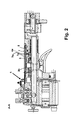
Figur 2- eine Axial-Schnittansicht zur Veranschaulichung des Innenaufbaus der Seitenmarkeneinrichtung gemäß
Figur 1 , insbesondere zur Veranschaulichung der Anordnung und der Funktionsweise des unterhalb der Saugplatteneinrichtung angeordneten Schließorgans.
- FIG. 1
- a plan view of a side marker device according to the invention, which is provided as such with an adjusting device for adjusting the air flow through a Saugplatteneinrichtung;
- FIG. 2
- an axial sectional view for illustrating the internal structure of the side marker device according to
FIG. 1 , in particular for illustrating the arrangement and the mode of operation of the closure member arranged below the suction plate device.
Die in
Die Seitenmarkeneinrichtung umfasst weiterhin eine Saugplatteneinrichtung 3, die bei diesem Ausführungsbeispiel als Lochplattenstruktur ausgeführt ist, die mehrere sich zwischen der hier erkennbaren Saugplattenoberseite 3a und einer darunter liegenden Saugplattenunterseite 3b (siehe
Wie nachfolgend in Verbindung mit
Hierdurch wird es möglich, die durch die Saugplatteneinrichtung 3 auf den über diese laufenden Bedruckstoff ausgeübte Saugkraft einzustellen ohne dass hierzu besondere Änderungen des an der Saugkanaleinrichtung 5 anliegenden Unterdrucks vorgenommen werden müssen. In besonders vorteilhafter Weise wird es hierdurch möglich, die Saugcharakteristik ohne Austausch der Saugplatteneinrichtung 3 auf die mechanischen Eigenschaften des Bedruckstoffs abzustimmen.As a result, it is possible to adjust the suction force exerted by the suction plate device 3 on the printing material running on it without the need for special changes to the negative pressure applied to the
Wie aus
Das Schließorgan 7 ist bei diesem Ausführungsbeispiel als Tellerelement ausgeführt dessen Abstand zur Saugplattenunterseite 3b einstellbar veränderbar ist. Bei dem hier gezeigten Ausführungsbeispiel umfasst das Schließorgan 7 einen Gewindezapfenabschnitt 8 der in einer entsprechenden Innengewindebohrung sitzt. Hierdurch wird es möglich, den Abstand A zwischen einer der Saugplattenunterseite 3b zugewandten Kopffläche 7a des Schließorgans und der Saugplatteneinrichtung 3 durch entsprechendes Drehen des Schließorgans 7 bedarfsgerecht einzustellen. Bei dem hier gezeigten Ausführungsbeispiel ist in der Saugplatteneinrichtung 3 eine Durchgangsöffnung 4a vorgesehen, die ebenfalls als Saugbohrung fungiert und zusätzlich derart ausgebildet und angeordnet ist, dass über diese ein Steckschlüssel in eine beispielsweise als Inbusbohrung ausgebildete Schlüsselöffnung 7b des Schließorgans 7 einsteckbar ist.The closing member 7 is executed in this embodiment as a plate member whose distance to the
Obgleich bei dem hier gezeigten Ausführungsbeispiel nicht realisiert, ist es möglich, mehrere, derartige Schließelemente vorzusehen und damit beispielsweise einen noch größeren Bereich der in der Saugplatteneinrichtung 3 ausgebildeten Durchgangsöffnungen hinsichtlich der über diese bewerkstelligten Saugwirkung abzustimmen.Although not realized in the embodiment shown here, it is possible to provide a plurality of such closing elements and thus, for example, to tune an even larger area of the passage openings formed in the suction plate device 3 with regard to the suction effect accomplished via the latter.
Alternativ zu dem hier beschriebenen Ausführungsbeispiel des Schließorgans als normal zur Saugplatteneinrichtung 3 verlagerbare Struktur ist es auch möglich, die Absperrung bestimmter Bohrungen der Saugplatteneinrichtung 3 durch anderweitige Mechaniken, insbesondere Schiebeblendeneinrichtungen, die als solche im Bereich der Unterseite der Saugplatteneinrichtung 3 parallel zu dieser verlagerbar sind, einzustellen. Es ist auch möglich, unmittelbar an der Saugplatteneinrichtung 3 eine Aufhängungseinrichtung für das Schließorgan 7 auszubilden.As an alternative to the embodiment of the closing element described here as a structure which can be displaced normally with respect to the suction plate device 3, it is also possible to shut off certain holes of the suction plate device 3 by other mechanisms, in particular sliding diaphragm devices, which are displaceable parallel thereto in the region of the underside of the suction plate device 3, adjust. It is also possible to form a suspension device for the closing member 7 directly on the Saugplatteneinrichtung 3.
Durch zumindest teilweises Abdecken der Saugöffnungen, insbesondere einer Saugöffnungsgruppe wird die Funktionsfläche verringert, oder in Umkehrung vergrößert. Dadurch wird die im Bereich der Saugplatteneinrichtung herrschende Saugkraft verkleinert oder vergrößert. Es können unterschiedlichste Bedruckstoffe verarbeitet werden, ohne dass die Saugplatte gewechselt werden muss.By at least partially covering the suction openings, in particular a Saugöffnungsgruppe the functional area is reduced, or increased in inversion. As a result, the suction force prevailing in the region of the suction plate device is reduced or increased. It can be processed a variety of substrates, without the suction plate must be changed.
Die Erfindung kann bei zahlreichen Bauformen pneumatischer Seitenmarken angewendet werden. Die erfindungsgemäße Seitenmarkeneinrichtung kann insbesondere auch durch Umrüstung vorhandener Seitenmarkeneinrichtungen realisiert werden, indem ein erfindungsgemäßes Schließelement in diese herkömmlichen Seitenmarkeneinrichtungen eingebunden wird. Dies kann insbesondere erfolgen indem die herkömmliche Saugplatteneinrichtung durch eine spezielle erfindungsgemäße Sauplatteneinrichtung ersetzt wird, wobei diese spezielle Saugplatteneinrichtung vorzugsweise so gestaltet ist, dass an dieser bereits die entsprechende Anbindung für das Schließelement vorgesehen ist. Das Schließelement kann weiterhin so gestaltet sein, dass durch dieses Schieber- oder Stempelflächen bereitgestellt werden durch welche in Abhängigkeit von der Positionierung des Schließelementes gegenüber Saugplatteneinrichtung bestimmte Durchgangsquerschnittseinstellungen und/oder Aktivierungsmuster für die Saugöffnungen der Saugplatteneinrichtung erreicht werden.The invention can be applied to numerous types of pneumatic side brands. In particular, the side marker device according to the invention can also be realized by retrofitting existing side marker devices by incorporating a closure element according to the invention into these conventional side marker devices. This can be done in particular by the conventional Saugplatteneinrichtung is replaced by a special invention Sauplatteneinrichtung, this special Saugplatteneinrichtung is preferably designed so that the corresponding connection for the closing element is already provided on this. The closing element can continue be designed so that are provided by this slide or stamp surfaces through which certain passage cross-section settings and / or activation pattern for the suction openings of the Saugplatteneinrichtung be achieved depending on the positioning of the closing element relative to Saugplatteneinrichtung.
- 11
- Anschlagattack
- 22
- AnschlageinstellmechanikAnschlageinstellmechanik
- 33
- SaugplatteneinrichtungSaugplatteneinrichtung
- 3a3a
- SaugplattenoberseiteSaugplattenoberseite
- 3b3b
- SauplattenunterseiteSauplattenunterseite
- 44
- Saugöffnungensuction ports
- 4a4a
- hinsichtlich des Luftdurchsatzes einstellbare Saugöffnungenwith regard to the air flow adjustable suction openings
- 55
- SaugkanaleinrichtungSaugkanaleinrichtung
- 77
- Schließorganclosing member
- 7a7a
- Kopfflächehead face
- 7b7b
- SchlüsseleinsteckbohrungSchlüsseleinsteckbohrung
- 88th
- Gewindeabschnittthreaded portion
- BB
- Bogenbow
- KK
- Anschlagflächestop surface
- LL
- Längskantelongitudinal edge
Claims (13)
dass eine Stelleinrichtung vorgesehen ist, zur Einstellung des Luftdurchsatzes durch die Saugplatteneinrichtung (3).Side marker device for a sheet-fed press, with:
in that an adjusting device is provided for adjusting the air flow rate through the suction plate device (3).
dadurch gekennzeichnet,
dass die Stelleinrichtung ein Schließorgan (7) umfasst, das zur einstellbaren Veränderung eines Strömungswegquerschnittes ausgebildet ist.Side marker device according to claim 1,
characterized,
that the actuating device comprises a closing member (7) which is adapted for adjustable variation of a Strömungswegquerschnittes.
dadurch gekennzeichnet,
dass das Schließorgan (7) derart ausgebildet ist, dass durch dieses ein Teil der die Saugöffnungen (4) bildenden Bohrungen absperrbar ist.Side marker device according to claim 2,
characterized,
in that the closing member (7) is designed in such a way that a part of the bores forming the suction openings (4) can be shut off by it.
dadurch gekennzeichnet,
dass das Schließorgan (7) als Tellerelement ausgeführt ist, dessen Abstand zur Saugplattenunterseite (3b) einstellbar veränderbar ist.Side marker device according to claim 3,
characterized,
in that the closing member (7) is designed as a plate element whose distance from the suction plate underside (3b) is adjustably changeable.
dadurch gekennzeichnet,
dass das Schließorgan (7) einen Gewindezapfenabschnitt (8) umfasst, und
dass der Abstand einer der Saugplattenunterseite (3b) zugewandten Kopffläche (7a) des Schließorgans (7) durch entsprechendes Drehen des Schließorgans (7) veränderbar ist.Side marker device according to claim 4,
characterized,
that the closing member (7) comprises a threaded pin portion (8), and
in that the distance between a head surface (7a) of the closing member (7) facing the underside of the suction plate (3b) can be changed by corresponding rotation of the closing member (7).
dadurch gekennzeichnet,
dass die Saugplatteneinrichtung (3) an ein Schlittenelement angebunden ist.Side marker device according to at least one of claims 1 to 6,
characterized,
that the Saugplatteneinrichtung (3) is connected to a carriage member.
dadurch gekennzeichnet,
dass das Schließorgan (7) ebenfalls in das Schlittenelement eingebunden ist.Side marker device according to claim 6,
characterized,
that the closing member (7) is also integrated in the carriage element.
dadurch gekennzeichnet,
dass ein Druckwandler vorgesehen ist, zur Einstellung des an der Saugkanaleinrichtung angelegten Unterdrucks.Side marker device according to at least one of claims 1 to 7,
characterized,
that a pressure transducer is provided for adjusting the voltage applied to the Saugkanaleinrichtung vacuum.
dadurch gekennzeichnet,
dass die Stelleinrichtung durch ein gegenüber der Saugplatteneinrichtung (3) einstellbar veränderbar positionierbares Schließorgan (7) gebildet ist.Side marker device according to at least one of claims 1 to 9,
characterized,
that the actuating device positionable adjustably variable by a relative to the Saugplatteneinrichtung (3) closing member (7) is formed.
dass ein Schließorgan vorgesehen ist, durch welches der Luftdurchsatz durch einen Teil der Saugöffnungen einstellbar veränderbar ist.Side marker device for a sheet-fed press, with:
that a closing member is provided, through which the air flow through a part of the suction openings is adjustably changeable.
dadurch gekennzeichnet,
dass die hinsichtlich des Luftdurchsatzes über das Schließorgan (7) steuerbaren Durchtrittsöffnungen (4) sich innerhalb einer Kreiszone befinden.Side marker device according to claim 10,
characterized,
that with respect to the air flow rate through the closing member (7) controllable passage openings (4) are located within a circular zone.
dadurch gekennzeichnet,
dass ein für den Luftdurchsatz maßgeblicher Strömungsquerschnitt durch die Saugplatteneinrichtung (3) und ein gegenüber dieser verlagerbares Schließorgan (7) einstellbar ist.Side marker device according to claim 12,
characterized,
in that a flow cross section which is decisive for the air throughput is adjustable by the suction plate device (3) and a closing member (7) which can be displaced with respect to this.
Applications Claiming Priority (1)
| Application Number | Priority Date | Filing Date | Title |
|---|---|---|---|
| DE202007008061U DE202007008061U1 (en) | 2007-06-08 | 2007-06-08 | Page marking device for sheet-fed printing machine, has suction plate device with suction plate upper and lower sides, and adjusting device, which is provided for adjusting air flow rate through suction plate device |
Publications (1)
| Publication Number | Publication Date |
|---|---|
| EP2000304A2 true EP2000304A2 (en) | 2008-12-10 |
Family
ID=38336590
Family Applications (1)
| Application Number | Title | Priority Date | Filing Date |
|---|---|---|---|
| EP08157244A Withdrawn EP2000304A2 (en) | 2007-06-08 | 2008-05-30 | Pneumatic side marking device for a sheet fed printing press |
Country Status (3)
| Country | Link |
|---|---|
| EP (1) | EP2000304A2 (en) |
| JP (1) | JP2008302695A (en) |
| DE (1) | DE202007008061U1 (en) |
Families Citing this family (4)
| Publication number | Priority date | Publication date | Assignee | Title |
|---|---|---|---|---|
| DE102010064064B4 (en) * | 2010-12-23 | 2023-03-09 | manroland sheetfed GmbH | Sheet Alignment Procedure |
| DE102012024619A1 (en) * | 2012-12-17 | 2014-06-18 | Heidelberger Druckmaschinen Ag | Suction air adaptation to sheet format |
| CN103287087A (en) * | 2013-04-26 | 2013-09-11 | 新乡市新机创新机械有限公司 | Pneumatic side lay device of printing machine |
| CN105366394B (en) * | 2015-11-27 | 2017-12-19 | 天津长荣科技集团股份有限公司 | A kind of air-sucking paper-conveying mechanism automatic adjustment system and its method of work |
Family Cites Families (2)
| Publication number | Priority date | Publication date | Assignee | Title |
|---|---|---|---|---|
| JP4723053B2 (en) * | 1999-03-19 | 2011-07-13 | ハイデルベルガー ドルツクマシーネン アクチエンゲゼルシヤフト | Method and apparatus for controlling the negative pressure level of a lateral puller |
| DE10055584B4 (en) * | 1999-12-16 | 2011-04-14 | Heidelberger Druckmaschinen Ag | Device for laterally aligning sheets |
-
2007
- 2007-06-08 DE DE202007008061U patent/DE202007008061U1/en not_active Expired - Lifetime
-
2008
- 2008-05-30 EP EP08157244A patent/EP2000304A2/en not_active Withdrawn
- 2008-06-06 JP JP2008149819A patent/JP2008302695A/en active Pending
Non-Patent Citations (1)
| Title |
|---|
| "Helmut Teschner, Offsetdrucktechnik", 1989, FACHSCHRIFTEN-VERLAG GMBH, pages: 456 - 457 |
Also Published As
| Publication number | Publication date |
|---|---|
| DE202007008061U1 (en) | 2007-08-09 |
| JP2008302695A (en) | 2008-12-18 |
Similar Documents
| Publication | Publication Date | Title |
|---|---|---|
| DE19854844A1 (en) | Control for suction air on openings in printer cylinder | |
| EP1749773B1 (en) | Transport system for a metal sheet printing machine or a metal sheet painting machine | |
| DE2737680B2 (en) | Spray gun | |
| EP2000304A2 (en) | Pneumatic side marking device for a sheet fed printing press | |
| DE10220889C5 (en) | Adjustment device for hydrostatic piston machines | |
| DE19817175A1 (en) | Device to deliver especially ragged flow of paper sheets to processing machine | |
| DE2722439C2 (en) | Device for the lateral alignment of sheets on printing machines or the like. | |
| DE3931995C2 (en) | ||
| EP0386470B1 (en) | Device for requesting sheet length in a sheet-processing machine, particularly in a printing machine sheet rotary | |
| DE3716085C2 (en) | ||
| EP0924069A2 (en) | Sheet guiding device in a printing machine | |
| EP1970608B1 (en) | Choke valve | |
| DE69507792T2 (en) | Suction device for printing press | |
| EP0082260A1 (en) | Device for the side registration of sheets in a printing machine | |
| DE102021200977B4 (en) | Valve device and method | |
| DE102007042534B3 (en) | suction roller | |
| DE102011084210B4 (en) | Sheet guiding cylinder with at least one pneumatically controllable sheet holding device | |
| DE3710329A1 (en) | Device for adjusting lateral stops in sheet deliverers | |
| DE10127250A1 (en) | Front marker for sheet on feeder table, is springy, and has adjustment, fixed to swivel holder, with detents and catches. | |
| EP2620400A1 (en) | Transport system for transporting sheet panels in a sheet printing or coating device | |
| WO2006024179A1 (en) | Device for applying a printing plate | |
| DE10023431B4 (en) | Suction cups in turning drums | |
| DE2558414A1 (en) | COMBUSTION ENGINE WITH A CONTROL SYSTEM FOR EXHAUST GAS EMISSION | |
| DE3628788A1 (en) | Blower device in printing machines | |
| DE102021105175A1 (en) | Valve device for a packaging machine |
Legal Events
| Date | Code | Title | Description |
|---|---|---|---|
| PUAI | Public reference made under article 153(3) epc to a published international application that has entered the european phase |
Free format text: ORIGINAL CODE: 0009012 |
|
| AK | Designated contracting states |
Kind code of ref document: A2 Designated state(s): AT BE BG CH CY CZ DE DK EE ES FI FR GB GR HR HU IE IS IT LI LT LU LV MC MT NL NO PL PT RO SE SI SK TR |
|
| AX | Request for extension of the european patent |
Extension state: AL BA MK RS |
|
| STAA | Information on the status of an ep patent application or granted ep patent |
Free format text: STATUS: THE APPLICATION HAS BEEN WITHDRAWN |
|
| 18W | Application withdrawn |
Effective date: 20100923 |