EP2000304A2 - Dispositif pneumatique de repérage latéral pour une presse d'impression pour feuilles - Google Patents
Dispositif pneumatique de repérage latéral pour une presse d'impression pour feuilles Download PDFInfo
- Publication number
- EP2000304A2 EP2000304A2 EP08157244A EP08157244A EP2000304A2 EP 2000304 A2 EP2000304 A2 EP 2000304A2 EP 08157244 A EP08157244 A EP 08157244A EP 08157244 A EP08157244 A EP 08157244A EP 2000304 A2 EP2000304 A2 EP 2000304A2
- Authority
- EP
- European Patent Office
- Prior art keywords
- suction
- sheet
- closing member
- side marker
- saugplatteneinrichtung
- Prior art date
- Legal status (The legal status is an assumption and is not a legal conclusion. Google has not performed a legal analysis and makes no representation as to the accuracy of the status listed.)
- Withdrawn
Links
- 238000007639 printing Methods 0.000 title description 8
- 239000003550 marker Substances 0.000 claims description 28
- 239000000463 material Substances 0.000 description 4
- 239000000758 substrate Substances 0.000 description 3
- 230000000694 effects Effects 0.000 description 2
- 230000007246 mechanism Effects 0.000 description 2
- 230000004913 activation Effects 0.000 description 1
- 238000005516 engineering process Methods 0.000 description 1
- 238000003780 insertion Methods 0.000 description 1
- 230000037431 insertion Effects 0.000 description 1
- 238000007645 offset printing Methods 0.000 description 1
- 238000009420 retrofitting Methods 0.000 description 1
- 239000000725 suspension Substances 0.000 description 1
Images

Classifications
-
- B—PERFORMING OPERATIONS; TRANSPORTING
- B41—PRINTING; LINING MACHINES; TYPEWRITERS; STAMPS
- B41F—PRINTING MACHINES OR PRESSES
- B41F21/00—Devices for conveying sheets through printing apparatus or machines
- B41F21/14—Adjusting lateral edges, e.g. side stops
-
- B—PERFORMING OPERATIONS; TRANSPORTING
- B65—CONVEYING; PACKING; STORING; HANDLING THIN OR FILAMENTARY MATERIAL
- B65H—HANDLING THIN OR FILAMENTARY MATERIAL, e.g. SHEETS, WEBS, CABLES
- B65H9/00—Registering, e.g. orientating, articles; Devices therefor
- B65H9/10—Pusher and like movable registers; Pusher or gripper devices which move articles into registered position
- B65H9/103—Pusher and like movable registers; Pusher or gripper devices which move articles into registered position acting by friction or suction on the article for pushing or pulling it into registered position, e.g. against a stop
- B65H9/105—Pusher and like movable registers; Pusher or gripper devices which move articles into registered position acting by friction or suction on the article for pushing or pulling it into registered position, e.g. against a stop using suction means
-
- B—PERFORMING OPERATIONS; TRANSPORTING
- B65—CONVEYING; PACKING; STORING; HANDLING THIN OR FILAMENTARY MATERIAL
- B65H—HANDLING THIN OR FILAMENTARY MATERIAL, e.g. SHEETS, WEBS, CABLES
- B65H2406/00—Means using fluid
- B65H2406/30—Suction means
- B65H2406/34—Suction grippers
- B65H2406/342—Suction grippers being reciprocated in a rectilinear path
-
- B—PERFORMING OPERATIONS; TRANSPORTING
- B65—CONVEYING; PACKING; STORING; HANDLING THIN OR FILAMENTARY MATERIAL
- B65H—HANDLING THIN OR FILAMENTARY MATERIAL, e.g. SHEETS, WEBS, CABLES
- B65H2406/00—Means using fluid
- B65H2406/30—Suction means
- B65H2406/36—Means for producing, distributing or controlling suction
Definitions
- the invention relates to a pneumatic side marker device for a sheet-fed printing machine as such comprises a suction plate via which a sheet can be sucked and moved under a corresponding transverse movement of the suction plate against a lateral sheet stop to the sheet-shaped substrate by applying the aligned in the sheet running direction longitudinal edges at those sheet stop defined laterally align.
- This pneumatic side marker device comprises a flat and provided with numerous designed as through holes suction openings suction plate.
- the invention has for its object to provide solutions by which it is possible to provide a pneumatic side marker device with the different depending on the print job properties of the printing material particularly advantageous account can be taken.
- the adjusting device is designed such that it comprises a closing member, through which the cross section of the respective suction opening extending flow path is adjustable variable.
- this closing member may in particular be designed such that at least part of the holes opening into the suction openings can be shut off by it.
- the closing member is designed as a plate element whose distance to the Saugplattenunterseite is adjustable adjustable.
- the closing member may for this purpose be provided, for example, with a threaded pin section, which is seated in a corresponding threaded bush, so that the distance of a head surface facing the suction plate underside can be variably changed by corresponding rotation of the closing member.
- a socket wrench in particular an Allen key in a substantially centrally formed in the plate member insertion
- the closing member is preferably designed so that it can be shut off, or at least with regard to the suction power controlled by this a certain group of passages of Saugplatten driven.
- the Saugplatten pain preferably comprises a second group of suction openings whose suction is not affected by the closing member, or only to a small extent.
- the suction openings may be arranged so that the suction openings covered by the closing member are located within a substantially circular zone whereas the suction openings not covered by the closing means are outside this zone.
- the suction plate device according to the invention is preferably connected to a carriage element.
- the closing member may be integrated directly into this carriage member so that the Saugplatten dressed and the closing member are displaced together in a direction aligned transversely to the direction of sheet travel stroke direction.
- further adjusting means are provided, by which also the total applied to the suction channel vacuum can be fixed adjustable.
- pneumatic side marker device serves as such the lateral alignment of an arcuate substrate B by the longitudinal side edge L is brought into contact with a sheet stop 1.
- the sheet stop 1 is formed in this embodiment as a cuboid web element.
- the sheet stop is preferably incorporated into the side mark device in such a way that its orientation can be variably adjusted, for example, via an adjustment mechanism 2.
- the sheet stop 1 forms a provision for providing a contact surface for the sheet longitudinal edge L provided stop surface K.
- the side marker device further comprises a Saugplatten driving 3, which is designed in this embodiment as a perforated plate structure, the plurality between the here recognizable Saugplattenoberseite 3a and an underlying Saugplattenunterseite 3b (see FIG. 2 ) has extending through holes 4. These through holes 4 form numerous, expiring in the Saugplattenoberseite, suction openings.
- the through-holes 4 communicate via a channel system, which can not be seen in detail in this illustration, with a suction channel device 5, which here comprises a section designed as a pipe spigot, which can be connected, for example, via a flexible hose line to a vacuum source, around the suction openings at a pressure below the ambient pressure level To pressurize.
- the pneumatic side marker device is characterized in that an adjusting device is provided for adjusting the air flow rate through the Saugplatten worn 3.
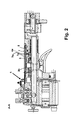
- This adjusting device comprises in the present embodiment, a closing member 7 (see. FIG. 2 ) through which the air flow can be adjusted by the here through (highlighted with thickened line) lying within a circular zone through holes 4a.
- the adjusting device 7 is located in a lying below the Saugplatten gifted 3 area.
- the closing member 7 is formed such that only a part of the suction openings forming holes 4 can be shut off by this.
- the closing member 7 is executed in this embodiment as a plate member whose distance to the Saugplattenunterseite 3b is adjustable adjustable.
- the closing member 7 comprises a threaded pin portion 8 which sits in a corresponding internally threaded bore. This makes it possible to adjust the distance A between a suction surface of the underside 3b facing head surface 7a of the closing member and the Saugplatten Huawei 3 by appropriate rotation of the closing member 7 as needed.
- a passage opening 4a is provided in the Saugplatten driven 3, which also acts as a suction hole and is additionally designed and arranged such that on this one Socket in a trained, for example, as an Allen key opening 7b of the closing member 7 can be inserted.
- the closing element described here as a structure which can be displaced normally with respect to the suction plate device 3, it is also possible to shut off certain holes of the suction plate device 3 by other mechanisms, in particular sliding diaphragm devices, which are displaceable parallel thereto in the region of the underside of the suction plate device 3, adjust. It is also possible to form a suspension device for the closing member 7 directly on the Saugplatten liked 3.
- the functional area is reduced, or increased in inversion.
- the suction force prevailing in the region of the suction plate device is reduced or increased. It can be processed a variety of substrates, without the suction plate must be changed.
- the invention can be applied to numerous types of pneumatic side brands.
- the side marker device according to the invention can also be realized by retrofitting existing side marker devices by incorporating a closure element according to the invention into these conventional side marker devices. This can be done in particular by the conventional Saugplatten listening is replaced by a special invention Sauplatten liked, this special Saugplatten noise is preferably designed so that the corresponding connection for the closing element is already provided on this.
- the closing element can continue be designed so that are provided by this slide or stamp surfaces through which certain passage cross-section settings and / or activation pattern for the suction openings of the Saugplatten headphones be achieved depending on the positioning of the closing element relative to Saugplatten listening.
Landscapes
- Engineering & Computer Science (AREA)
- Mechanical Engineering (AREA)
- Hooks, Suction Cups, And Attachment By Adhesive Means (AREA)
- Delivering By Means Of Belts And Rollers (AREA)
Applications Claiming Priority (1)
| Application Number | Priority Date | Filing Date | Title |
|---|---|---|---|
| DE202007008061U DE202007008061U1 (de) | 2007-06-08 | 2007-06-08 | Pneumatische Seitenmarkeneinrichtung für eine Bogendruckmaschine |
Publications (1)
| Publication Number | Publication Date |
|---|---|
| EP2000304A2 true EP2000304A2 (fr) | 2008-12-10 |
Family
ID=38336590
Family Applications (1)
| Application Number | Title | Priority Date | Filing Date |
|---|---|---|---|
| EP08157244A Withdrawn EP2000304A2 (fr) | 2007-06-08 | 2008-05-30 | Dispositif pneumatique de repérage latéral pour une presse d'impression pour feuilles |
Country Status (3)
| Country | Link |
|---|---|
| EP (1) | EP2000304A2 (fr) |
| JP (1) | JP2008302695A (fr) |
| DE (1) | DE202007008061U1 (fr) |
Families Citing this family (4)
| Publication number | Priority date | Publication date | Assignee | Title |
|---|---|---|---|---|
| DE102010064064B4 (de) * | 2010-12-23 | 2023-03-09 | manroland sheetfed GmbH | Verfahren zur Bogenausrichtung |
| DE102012024619A1 (de) * | 2012-12-17 | 2014-06-18 | Heidelberger Druckmaschinen Ag | Saugluftanpassung auf Bogenformat |
| CN103287087A (zh) * | 2013-04-26 | 2013-09-11 | 新乡市新机创新机械有限公司 | 印刷机气动侧规装置 |
| CN105366394B (zh) * | 2015-11-27 | 2017-12-19 | 天津长荣科技集团股份有限公司 | 一种吸风送纸机构自动调整系统及其工作方法 |
Family Cites Families (2)
| Publication number | Priority date | Publication date | Assignee | Title |
|---|---|---|---|---|
| JP4723053B2 (ja) * | 1999-03-19 | 2011-07-13 | ハイデルベルガー ドルツクマシーネン アクチエンゲゼルシヤフト | 横引き寄せ装置の負圧レベルを制御する方法および装置 |
| DE10055584B4 (de) * | 1999-12-16 | 2011-04-14 | Heidelberger Druckmaschinen Ag | Vorrichtung zum seitlichen Ausrichten von Bogen |
-
2007
- 2007-06-08 DE DE202007008061U patent/DE202007008061U1/de not_active Expired - Lifetime
-
2008
- 2008-05-30 EP EP08157244A patent/EP2000304A2/fr not_active Withdrawn
- 2008-06-06 JP JP2008149819A patent/JP2008302695A/ja active Pending
Non-Patent Citations (1)
| Title |
|---|
| "Helmut Teschner, Offsetdrucktechnik", 1989, FACHSCHRIFTEN-VERLAG GMBH, pages: 456 - 457 |
Also Published As
| Publication number | Publication date |
|---|---|
| DE202007008061U1 (de) | 2007-08-09 |
| JP2008302695A (ja) | 2008-12-18 |
Similar Documents
| Publication | Publication Date | Title |
|---|---|---|
| DE19854844A1 (de) | Vorrichtung zur Saugluftsteuerung | |
| EP1749773B1 (fr) | Système de transport pour une machine d'impression de feuilles de tôle ou une machine de laquage de feuilles de tôle | |
| DE2737680B2 (de) | Spritzpistole | |
| EP2000304A2 (fr) | Dispositif pneumatique de repérage latéral pour une presse d'impression pour feuilles | |
| DE10220889C5 (de) | Verstellvorrichtung für hydrostatische Kolbenmaschinen | |
| DE19817175A1 (de) | Vorrichtung zum Fördern eines insbesondere geschuppten Stroms von Bogen zu einer bogenverarbeitenden Maschine | |
| DE2722439C2 (de) | Vorrichtung zum seitlichen Ausrichten von Bogen an Druckmaschinen o.dgl. | |
| DE3931995C2 (fr) | ||
| EP0386470B1 (fr) | Dispositif pour demander la longueur d'une feuille dans une machine de traitement de feuilles, notamment dans une machine rotative à imprimer pour feuilles | |
| DE3716085C2 (fr) | ||
| EP0924069A2 (fr) | Dispositif de guidage de feuilles dans une machine à imprimer | |
| EP1970608B1 (fr) | Valve d'étranglement | |
| DE69507792T2 (de) | Saugvorrichtung für Druckmaschine | |
| EP0082260A1 (fr) | Dispositif d'alignement latéral de feuilles pour une machine à imprimer | |
| DE102021200977B4 (de) | Ventilvorrichtung und Verfahren | |
| DE102007042534B3 (de) | Saugwalzensystem | |
| DE102011084210B4 (de) | Bogenführungszylinder mit wenigstens einer pneumatisch steuerbaren Bogenhaltevorrichtung | |
| DE3710329A1 (de) | Einrichtung zum einstellen von seitenanschlaegen in bogenauslegern | |
| DE10127250A1 (de) | Vorrichtung zum Festlegen der Lage eines Bogens auf einem Anlagetisch | |
| EP2620400A1 (fr) | Dispositif de tansport de tableaux en tôle dans une machine d'impression de tôle ou une machine de laquage de tôle | |
| WO2006024179A1 (fr) | Dispositif de fixation de planche d'impression | |
| DE10023431B4 (de) | Sauger in Wendetrommeln | |
| DE2558414A1 (de) | Verbrennungskraftmaschine mit einer steueranlage fuer die abgasemission | |
| DE3628788A1 (de) | Blaseinrichtung in druckmaschinen | |
| DE102021105175A1 (de) | Ventilvorrichtung für eine Verpackungsmaschine |
Legal Events
| Date | Code | Title | Description |
|---|---|---|---|
| PUAI | Public reference made under article 153(3) epc to a published international application that has entered the european phase |
Free format text: ORIGINAL CODE: 0009012 |
|
| AK | Designated contracting states |
Kind code of ref document: A2 Designated state(s): AT BE BG CH CY CZ DE DK EE ES FI FR GB GR HR HU IE IS IT LI LT LU LV MC MT NL NO PL PT RO SE SI SK TR |
|
| AX | Request for extension of the european patent |
Extension state: AL BA MK RS |
|
| STAA | Information on the status of an ep patent application or granted ep patent |
Free format text: STATUS: THE APPLICATION HAS BEEN WITHDRAWN |
|
| 18W | Application withdrawn |
Effective date: 20100923 |