EP2000268A2 - Appareil de commande d'un robot - Google Patents
Appareil de commande d'un robot Download PDFInfo
- Publication number
- EP2000268A2 EP2000268A2 EP08010116A EP08010116A EP2000268A2 EP 2000268 A2 EP2000268 A2 EP 2000268A2 EP 08010116 A EP08010116 A EP 08010116A EP 08010116 A EP08010116 A EP 08010116A EP 2000268 A2 EP2000268 A2 EP 2000268A2
- Authority
- EP
- European Patent Office
- Prior art keywords
- control
- robot
- axis
- follow
- external force
- Prior art date
- Legal status (The legal status is an assumption and is not a legal conclusion. Google has not performed a legal analysis and makes no representation as to the accuracy of the status listed.)
- Withdrawn
Links
Images


Classifications
-
- B—PERFORMING OPERATIONS; TRANSPORTING
- B25—HAND TOOLS; PORTABLE POWER-DRIVEN TOOLS; MANIPULATORS
- B25J—MANIPULATORS; CHAMBERS PROVIDED WITH MANIPULATION DEVICES
- B25J9/00—Programme-controlled manipulators
- B25J9/16—Programme controls
- B25J9/1628—Programme controls characterised by the control loop
-
- G—PHYSICS
- G05—CONTROLLING; REGULATING
- G05B—CONTROL OR REGULATING SYSTEMS IN GENERAL; FUNCTIONAL ELEMENTS OF SUCH SYSTEMS; MONITORING OR TESTING ARRANGEMENTS FOR SUCH SYSTEMS OR ELEMENTS
- G05B2219/00—Program-control systems
- G05B2219/30—Nc systems
- G05B2219/41—Servomotor, servo controller till figures
- G05B2219/41012—Adjust feedforward gain
-
- G—PHYSICS
- G05—CONTROLLING; REGULATING
- G05B—CONTROL OR REGULATING SYSTEMS IN GENERAL; FUNCTIONAL ELEMENTS OF SUCH SYSTEMS; MONITORING OR TESTING ARRANGEMENTS FOR SUCH SYSTEMS OR ELEMENTS
- G05B2219/00—Program-control systems
- G05B2219/30—Nc systems
- G05B2219/41—Servomotor, servo controller till figures
- G05B2219/41028—Select gain with memory, rom table
Definitions
- This invention relates to a robot control apparatus for soft control of an industrial robot.
- a robot control technique adapted to change the softness on the orthogonal coordinate system by controlling a servo motor for driving the robot axes.
- a robot control apparatus As a conventional technique for maintaining the robot orientation during the soft control operation, a "robot control apparatus" is disclosed in the below-mentioned Patent Document 1 (Patent Publication No. 3473834 ).
- the robot can be controlled in such a way that the soft operation in translation can be performed while the tool mounted at the forward end of the robot hand is kept in a predetermined orientation.
- This apparatus has no means for requesting a command for the control axes not in soft control operation in accordance with the direction to follow an external force.
- Patent Document 2 Japanese Unexamined Patent Publication (Kokai) No. 8-155868 , on the other hand, discloses a robot control method for controlling the relief follow-up operation in a predetermined direction with respect to an external force exerted on the tool of an industrial robot. This method also lacks means for requesting a command for control axes not in soft control operation in accordance with the direction to follow an external force.
- the problem occurs in that the follow-up direction cannot be designated or, if any can be designated, the motion in the direction to follow is hampered by the torque for controlling the directions not to follow.
- This invention has been achieved in view of the problem described above, and the object thereof is to provide a robot control apparatus in which while maintaining the orientation of the robot in soft control operation, the motion in the direction to follow is not hampered even in the case in which a force is exerted in a direction displaced from the direction to follow.
- a robot control apparatus having position and velocity control loops for each robot control axis, comprising means for inputting the information on the direction of the forward end of the robot arm to follow an external force; means for setting the position control gain and the velocity control gain of a specified control axis at a lower level than the position control gain and the velocity control gain, respectively, of the control axes other than the specified control axis; means for determining the orientation to be assumed by the forward end of the robot arm while following the external force, i.e.
- the robot control apparatus is so configured that the gain for a specified control axis is reduced during the soft control operation on the one hand and a command is determined and applied to the control axes not in soft control operation based on the direction to follow the external force.
- a robot control apparatus wherein the specified control axis is preferably set by manual input.
- a robot control apparatus wherein the specified control axis is set automatically in accordance with the direction in which the forward end of the robot arm is to follow the external force and the robot position in which the external force is applied to the forward end of the robot arm.
- the gain for a specified control axis is reduced during the soft control operation on the one hand and a command is determined and applied to the control axes not in soft control operation based on the direction to follow the external force on the other hand, so that the direction to follow can be designated while maintaining the orientation of the robot in soft control operation, the motion in the direction to follow is not hampered by the torque for controlling the directions not to follow, and even in the case in which a force is applied in the direction displaced from the direction to follow, the motion in the direction to follow is made possible with a small force.
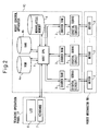
- Fig. 1 is a schematic diagram showing the general configuration of the robot control system according to an embodiment of the invention.
- the robot control system shown in Fig. 1 comprises a robot control apparatus RC for controlling the whole system including the servo control (soft control) of an industrial robot; and a robot mechanism RM for driving the industrial robot with a servo motor or the like in accordance with a control signal from the robot control apparatus RC.
- the robot control system further comprises a teaching operation panel TP including a parameter setting screen for the user to manually input the parameters for the soft control operation of the industrial robot.
- Fig. 2 is a block diagram showing the configuration of the robot control apparatus according to an embodiment of the invention.
- the configuration of the robot control apparatus used in this embodiment of the invention is shown in a simplified form.
- similar component elements to those described above are designated by the same reference numerals, respectively.
- the robot control apparatus shown in Fig. 2 includes a host CPU 1 for controlling the whole system, and a shared RAM memory 3 for delivering the motion command and the control signal output from the host CPU 1 to the processor of each digital servo circuit 2 described later or, conversely, delivering the various signals from the processor of the digital servo circuit 2 to the host CPU 1.
- Each digital servo (software servo) circuit 2 for executing the servo control operation described above is configured of a processor not shown in Fig. 2 and memories such as a ROM and a RAM.
- a ROM 4a, a RAM 4b, a nonvolatile memory 5 and a teaching operation panel TP are connected to the host CPU 1.
- the ROM 4a has stored therein various system programs.
- the RAM 4b is a memory used by the host CPU 1 for temporarily storing the data.
- the nonvolatile memory 5 has stored therein various programs on the specific operations of the robot and the related settings.
- the teaching operation panel TP includes a liquid crystal display (LCD) 6 and a keyboard 7 and adapted to input/change the program data and the related settings. Further, the robot mechanism RM includes a plurality of motors (such as servo motors) 8 for driving the robot in accordance with the motion command or the control signal from the host CPU 1.
- motors such as servo motors
- the nonvolatile memory 5 has stored therein the data on the softness in each direction on the orthogonal coordinate system input through the parameter setting screen for the orthogonal soft float from the teaching operation panel TP and the settings of the coordinate system.
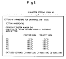
- the user first accesses the parameter setting screen 60 for the orthogonal soft float shown in Fig. 6 on the liquid crystal display 6 added to the teaching operation panel TP.
- a task coordinate system for carrying out the orthogonal soft float and the direction to follow the external force can be set on the parameter setting screen.
- the axis (control axis) reduced in gain during the soft control operation can also be set on the parameter setting screen.
- the user selects the joint axis having a large effect on the motion in the direction set to follow the external force (Y direction in the example shown in Fig. 6 ), and inputs the ratio ⁇ p between the position gain Ksp after reduction and the normal position gain Kp and the ratio ⁇ v between the velocity gain Ksv after reduction and the normal velocity gain Kv.
- the J1 axis is selected, and ⁇ p of 5 % and ⁇ v of 5 % are set for the J1 axis.
- the axis selection and the ratio setting described above may not be input by the user but may be determined by the robot control apparatus in accordance with a predetermined rule, and the result thus determined may be displayed on the parameter setting screen.
- a method can be used in which the Jacobian of the orthogonal travel distance in the direction to follow for the travel distance on each axis at the soft control starting point, for example, is calculated, and constants of the ratios ⁇ p and ⁇ v (for example, 10 % and 10 %, respectively) for the axis larger in Jacobian are set automatically.
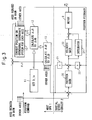
- Fig. 3 is a block diagram showing the control system in soft control operation according to this invention
- Fig. 4 a flowchart showing the host processing of the orthogonal soft float according to this invention
- Fig. 5 a flowchart showing the servo processing of the orthogonal soft float according to this invention.
- the orthogonal soft floating function is executed by reducing the position loop gain and the velocity loop gain using the preset ratios ⁇ p, ⁇ v for the axis to be reduced in gain at the time of starting the orthogonal soft float.
- step S11 the travel distances ⁇ J1 to ⁇ J6 to follow the external force are calculated. Further, as shown in step S12, the actual travel distance ⁇ J1 of the axis (for example, J1 axis) to be reduced in gain is detected.
- the axis for example, J1 axis
- step S13 the travel distances ⁇ J2 to ⁇ J6 required of the axes other than the axis to be reduced in gain are calculated. Furthermore, as shown in step S14, the required travel distances ⁇ J2 to ⁇ J6 are written in the shared memories. Now, the host processing of the orthogonal soft floating function is over.
- step S20 judges whether or not the axis (for example, the J1 axis) to be reduced in gain has been selected.
- step S20 In the case in which step S20 has judged that the axis to be reduced in gain has been selected, the process proceeds to step S21, where each process of the position loop, the integration and the velocity loop is executed using the position gain Ksp after gain reduction and the velocity gain Ksv after gain reduction. As a result, the position loop gain and the velocity loop gain are controlled downward on the axis to be reduced in gain.
- step S20 has judged that an axis other than the axis to be reduced in gain has been selected, on the other hand, the process proceeds to step S22 and the required travel distance ⁇ Jx (in the case under consideration, Jx indicates an axis other than the axis to be reduced in gain) is read from the shared memory.
- step S23 the required travel distance ⁇ Jx is added to the input of the position loop while at the same time adding the differentiation of the required travel distance ⁇ Jx to the input of the velocity loop. Furthermore, as shown in step S24, each process of the position loop, the integration and the velocity loop is executed using the normal position gain Kp and the normal velocity gain Kv. As a result, the servo processing of the orthogonal soft floating function is completed.
- the host CPU 1 determines, in the blocks 10 to 12, the motion amount of each axis (travel distances ⁇ J1 to ⁇ J6 to follow the external force) in the case in which the tool center point (TCP) of the robot moves over a predetermined distance D, while maintaining the orientation of the forward end of the robot arm as of the time of starting the orthogonal soft float, in the direction /e ("/e" indicates -the- vector e) in which to follow the external force, from the present position /P1 ("/P1" indicates the vector P1) at the coordinate on the orthogonal coordinate system ⁇ 0.
- the motion amount of each axis can be calculated according to the equations described below.
- /P2 indicates the position of the robot that has traveled the predetermined distance D while maintaining the orientation of the forward end of the robot arm as of the time when the orthogonal soft float is started.
- the actual travel distance of the axis reduced in gain is detected.
- the actual travel distance of the J1 axis is determined as ⁇ J1.
- the travel distances ⁇ J2 to ⁇ J6 of the axes other than the axis reduced in gain are each sent to the digital servo circuit 2 ( Fig. 2 ) through the shared RAM.
- the travel distances ⁇ J2 to ⁇ J6 of the axes other than the axis reduced in gain are applied as an input to the position loop (the loop including the position gain block 20 and the position feedback path) on the one hand, and the differentiation of each of the travel distances ⁇ J2 to ⁇ J6 calculated by the differentiator 21 is applied as an input to the velocity loop (the loop including the velocity gain block 23 and the differentiator 22 related to the velocity feedback path) on the other hand.
- each digital servo circuit 2 executes the process in the position loop and the velocity loop and subjects the motors 8 in the robot to the digital servo control operation.
- the tool center point (TCP) of the robot can be moved while maintaining the orientation in the direction following the external force from the present position.
- the gravity moment and the torque equivalent to the Coulomb friction are stored in the integrator at the time of starting the soft control operation.
- the torque equivalent to the Coulomb friction is opposite to the external force, however, the motion could not be started inconveniently unless an extraneous external force to offset the torque is applied.
- a method of performing the preliminary operation in the direction to follow and integrating the torque in the direction compensating for the friction by the integrator of the velocity loop is often used in the actual production field. More specifically, the user adds a position control operation instruction to perform the preliminary operation before the soft control operation start instruction in the motion program.
- the direction and distance of the preliminary motion are set in advance, and upon receipt of the soft control operation start instruction, the preliminary motion is generated and performed by the interpreter of the control apparatus, after which the soft control operation is started.
- the function having a similar effect can be used for this embodiment.
- this embodiment is applicable to the function to achieve a similar effect in the case in which the distance for the preliminary motion is lacking for the reason of layout of the robot and the peripheral devices, in which case an amount corresponding to the torque integrated by the integrator in the preliminary motion is set in advance and this torque is applied to the output of the velocity loop during the execution of the soft control operation.
- this embodiment is applicable to the function in which upon application of an external force from one direction by applying a periodical torque of a sinusoidal wave, a triangular wave or a rectangular wave having an amplitude approximate to the magnitude of the static friction, the direction of the external force is coincident with that of the periodical torque and the sum of the torques exceeds the static friction so that the motion in the particular direction can be started.
- the coordinate system is required to be set in advance.
- a method of directly inputting the parameters of the coordinate system is generally employed.
- the direction of the coordinate system can be designated to facilitate the understanding intuitively by using the function of teaching two tool center points and setting the direction connecting the two points on one of the axes (for example, Z axis) of the task coordinate system for the orthogonal soft float or the direction of the preliminary motion.
- this invention can be used with a robot control system including the robot control apparatus for soft control operation of an industrial robot, wherein the gain is reduced for a specified control axis during the soft control operation on the one hand and a command is determined and applied to the control axes not in soft control operation based on the direction to follow the external force on the other hand, thereby making the softness changeable on the orthogonal coordinate by controlling the servo motor for driving the robot axes.
Landscapes
- Engineering & Computer Science (AREA)
- Robotics (AREA)
- Mechanical Engineering (AREA)
- Manipulator (AREA)
Applications Claiming Priority (1)
| Application Number | Priority Date | Filing Date | Title |
|---|---|---|---|
| JP2007150614A JP2008302449A (ja) | 2007-06-06 | 2007-06-06 | ロボット制御装置 |
Publications (1)
| Publication Number | Publication Date |
|---|---|
| EP2000268A2 true EP2000268A2 (fr) | 2008-12-10 |
Family
ID=39764933
Family Applications (1)
| Application Number | Title | Priority Date | Filing Date |
|---|---|---|---|
| EP08010116A Withdrawn EP2000268A2 (fr) | 2007-06-06 | 2008-06-03 | Appareil de commande d'un robot |
Country Status (4)
| Country | Link |
|---|---|
| US (1) | US20080303473A1 (fr) |
| EP (1) | EP2000268A2 (fr) |
| JP (1) | JP2008302449A (fr) |
| CN (1) | CN101318329A (fr) |
Cited By (1)
| Publication number | Priority date | Publication date | Assignee | Title |
|---|---|---|---|---|
| EP2243602A2 (fr) | 2009-04-22 | 2010-10-27 | KUKA Roboter GmbH | Procédé et dispositif de commande d'un manipulateur |
Families Citing this family (7)
| Publication number | Priority date | Publication date | Assignee | Title |
|---|---|---|---|---|
| JP2009066685A (ja) * | 2007-09-11 | 2009-04-02 | Sony Corp | ロボット装置及びロボット装置の制御方法 |
| JP5262880B2 (ja) * | 2009-03-18 | 2013-08-14 | 株式会社デンソーウェーブ | ロボット制御装置 |
| CN103101583A (zh) * | 2011-11-10 | 2013-05-15 | 中国科学院合肥物质科学研究院 | 一种全皮肤翻转运动软体机器人 |
| KR102543212B1 (ko) | 2015-10-26 | 2023-06-14 | (주)한화 | 로봇 제어 시스템 및 방법 |
| JP6616170B2 (ja) * | 2015-12-07 | 2019-12-04 | ファナック株式会社 | コアシートの積層動作を学習する機械学習器、積層コア製造装置、積層コア製造システムおよび機械学習方法 |
| JP2018176288A (ja) * | 2017-04-03 | 2018-11-15 | ファナック株式会社 | ロボットの教示装置 |
| EP3807058A1 (fr) * | 2018-06-15 | 2021-04-21 | Universal Robots A/S | Estimation de charge utile fixée à un bras de robot |
Citations (2)
| Publication number | Priority date | Publication date | Assignee | Title |
|---|---|---|---|---|
| JPH08155868A (ja) | 1994-11-30 | 1996-06-18 | Kawasaki Heavy Ind Ltd | ロボットの制御方法および装置 |
| JP3473834B2 (ja) | 1999-11-29 | 2003-12-08 | 株式会社安川電機 | ロボットの制御装置 |
Family Cites Families (12)
| Publication number | Priority date | Publication date | Assignee | Title |
|---|---|---|---|---|
| JP2875646B2 (ja) * | 1991-07-04 | 1999-03-31 | ファナック株式会社 | バックラッシ加速補正装置 |
| US6677722B2 (en) * | 2001-04-19 | 2004-01-13 | Toshiba Kikai Kabushiki Kaisha | Servo control method |
| JP3923047B2 (ja) * | 2003-03-04 | 2007-05-30 | ファナック株式会社 | 同期制御装置 |
| SE0301531L (sv) * | 2003-05-22 | 2004-11-23 | Abb Ab | A Control method for a robot |
| EP1652634B1 (fr) * | 2003-07-29 | 2011-12-28 | Panasonic Corporation | Procede de commande du bras d'un robot et dispositif de commande associe |
| JP4392251B2 (ja) * | 2004-01-07 | 2009-12-24 | オークマ株式会社 | 送り駆動系の制御装置 |
| US20060178775A1 (en) * | 2005-02-04 | 2006-08-10 | George Zhang | Accelerometer to monitor movement of a tool assembly attached to a robot end effector |
| TWI327260B (en) * | 2005-05-31 | 2010-07-11 | Mitsubishi Electric Corp | Motor control device |
| JP2007257515A (ja) * | 2006-03-24 | 2007-10-04 | Toshiba Mach Co Ltd | サーボモータの制御方法 |
| JP2008225533A (ja) * | 2007-03-08 | 2008-09-25 | Fanuc Ltd | サーボ制御装置 |
| JP4271249B2 (ja) * | 2007-06-14 | 2009-06-03 | ファナック株式会社 | 嵌合装置 |
| JP4847401B2 (ja) * | 2007-06-18 | 2011-12-28 | 本田技研工業株式会社 | 移動ロボットの駆動装置 |
-
2007
- 2007-06-06 JP JP2007150614A patent/JP2008302449A/ja active Pending
-
2008
- 2008-06-03 CN CNA2008100986265A patent/CN101318329A/zh active Pending
- 2008-06-03 EP EP08010116A patent/EP2000268A2/fr not_active Withdrawn
- 2008-06-04 US US12/132,879 patent/US20080303473A1/en not_active Abandoned
Patent Citations (2)
| Publication number | Priority date | Publication date | Assignee | Title |
|---|---|---|---|---|
| JPH08155868A (ja) | 1994-11-30 | 1996-06-18 | Kawasaki Heavy Ind Ltd | ロボットの制御方法および装置 |
| JP3473834B2 (ja) | 1999-11-29 | 2003-12-08 | 株式会社安川電機 | ロボットの制御装置 |
Cited By (2)
| Publication number | Priority date | Publication date | Assignee | Title |
|---|---|---|---|---|
| EP2243602A2 (fr) | 2009-04-22 | 2010-10-27 | KUKA Roboter GmbH | Procédé et dispositif de commande d'un manipulateur |
| EP2243602A3 (fr) * | 2009-04-22 | 2012-05-09 | KUKA Roboter GmbH | Procédé et dispositif de commande d'un manipulateur |
Also Published As
| Publication number | Publication date |
|---|---|
| US20080303473A1 (en) | 2008-12-11 |
| CN101318329A (zh) | 2008-12-10 |
| JP2008302449A (ja) | 2008-12-18 |
Similar Documents
| Publication | Publication Date | Title |
|---|---|---|
| EP2000268A2 (fr) | Appareil de commande d'un robot | |
| US11000949B2 (en) | Robot for controlling learning in view of operation in production line, and method of controlling the same | |
| US10259118B2 (en) | Robot system having function of simplifying teaching operation and improving operating performance by learning | |
| Nemec et al. | Human robot cooperation with compliance adaptation along the motion trajectory | |
| US7912584B2 (en) | Power consumption estimation apparatus | |
| EP2390064A1 (fr) | Appareil et procédé pour commander un bras de robot, robot, programme pour commander un bras de robot, et circuit électronique intégré | |
| US20110093120A1 (en) | Apparatus and method for adjusting parameter of impedance control | |
| EP2774729A1 (fr) | Système robotique et unité de commande de robot | |
| US20080077279A1 (en) | Robot controller performing soft control | |
| JP3681431B2 (ja) | 直交座標系上で柔らかさが調節可能なサーボ系 | |
| JP6973119B2 (ja) | ロボット制御装置及びロボットシステム | |
| JP3300625B2 (ja) | ロボットの制御方式 | |
| EP3315269A2 (fr) | Dispositif de réglage d'axe de coordonnées de commande de force, robot et procédé de réglage d'axe de coordonnées de commande de force | |
| CN108687758B (zh) | 机器人的移动速度控制装置及方法 | |
| US9298194B2 (en) | Method to control medical equipment | |
| EP3702860A1 (fr) | Dispositif de réglage de servomoteur et procédé de réglage de servomoteur | |
| EP0369026A1 (fr) | Procede de formation d'images a symetrie speculaire pour robots | |
| US10532460B2 (en) | Robot teaching device that sets teaching point based on motion image of workpiece | |
| JP4446068B2 (ja) | 工作機械用の数値制御装置および工作機械を制御する数値制御方法 | |
| JP5245384B2 (ja) | ロボット制御装置 | |
| US11400584B2 (en) | Teaching method | |
| JPH11104982A (ja) | ロボットの教示方法 | |
| JP4882990B2 (ja) | ロボット制御装置 | |
| JP3545486B2 (ja) | 同軸手首ロボットの姿勢制御動作における急動作回避方法 | |
| WO2024084544A1 (fr) | Dispositif de commande de robot |
Legal Events
| Date | Code | Title | Description |
|---|---|---|---|
| PUAI | Public reference made under article 153(3) epc to a published international application that has entered the european phase |
Free format text: ORIGINAL CODE: 0009012 |
|
| AK | Designated contracting states |
Kind code of ref document: A2 Designated state(s): AT BE BG CH CY CZ DE DK EE ES FI FR GB GR HR HU IE IS IT LI LT LU LV MC MT NL NO PL PT RO SE SI SK TR |
|
| AX | Request for extension of the european patent |
Extension state: AL BA MK RS |
|
| STAA | Information on the status of an ep patent application or granted ep patent |
Free format text: STATUS: THE APPLICATION HAS BEEN WITHDRAWN |
|
| 18W | Application withdrawn |
Effective date: 20090223 |