EP1999007B1 - Transmission directe à vitesse variable - Google Patents
Transmission directe à vitesse variable Download PDFInfo
- Publication number
- EP1999007B1 EP1999007B1 EP06830287A EP06830287A EP1999007B1 EP 1999007 B1 EP1999007 B1 EP 1999007B1 EP 06830287 A EP06830287 A EP 06830287A EP 06830287 A EP06830287 A EP 06830287A EP 1999007 B1 EP1999007 B1 EP 1999007B1
- Authority
- EP
- European Patent Office
- Prior art keywords
- friction element
- transmission system
- drive shaft
- direct drive
- drive transmission
- Prior art date
- Legal status (The legal status is an assumption and is not a legal conclusion. Google has not performed a legal analysis and makes no representation as to the accuracy of the status listed.)
- Active
Links
- 230000005540 biological transmission Effects 0.000 title claims abstract description 97
- 230000008878 coupling Effects 0.000 claims description 5
- 238000010168 coupling process Methods 0.000 claims description 5
- 238000005859 coupling reaction Methods 0.000 claims description 5
- 238000009434 installation Methods 0.000 claims description 4
- 230000001154 acute effect Effects 0.000 claims description 3
- 230000015572 biosynthetic process Effects 0.000 claims description 3
- 238000005452 bending Methods 0.000 claims description 2
- 230000007246 mechanism Effects 0.000 description 9
- 239000002184 metal Substances 0.000 description 6
- 230000008859 change Effects 0.000 description 4
- 238000006073 displacement reaction Methods 0.000 description 4
- 230000007704 transition Effects 0.000 description 4
- 239000000446 fuel Substances 0.000 description 3
- 238000012423 maintenance Methods 0.000 description 3
- 230000009194 climbing Effects 0.000 description 2
- 229910000831 Steel Inorganic materials 0.000 description 1
- 230000006978 adaptation Effects 0.000 description 1
- 230000002411 adverse Effects 0.000 description 1
- 230000015556 catabolic process Effects 0.000 description 1
- 238000006243 chemical reaction Methods 0.000 description 1
- 230000000694 effects Effects 0.000 description 1
- 230000002349 favourable effect Effects 0.000 description 1
- 239000012530 fluid Substances 0.000 description 1
- 210000000056 organ Anatomy 0.000 description 1
- 230000036316 preload Effects 0.000 description 1
- 230000004044 response Effects 0.000 description 1
- 238000007665 sagging Methods 0.000 description 1
- 239000010959 steel Substances 0.000 description 1
Images


Classifications
-
- B—PERFORMING OPERATIONS; TRANSPORTING
- B62—LAND VEHICLES FOR TRAVELLING OTHERWISE THAN ON RAILS
- B62M—RIDER PROPULSION OF WHEELED VEHICLES OR SLEDGES; POWERED PROPULSION OF SLEDGES OR SINGLE-TRACK CYCLES; TRANSMISSIONS SPECIALLY ADAPTED FOR SUCH VEHICLES
- B62M13/00—Transmissions characterised by use of friction rollers engaging the periphery of the ground wheel
- B62M13/04—Transmissions characterised by use of friction rollers engaging the periphery of the ground wheel with means for moving roller into driving contact with ground wheel
-
- B—PERFORMING OPERATIONS; TRANSPORTING
- B62—LAND VEHICLES FOR TRAVELLING OTHERWISE THAN ON RAILS
- B62M—RIDER PROPULSION OF WHEELED VEHICLES OR SLEDGES; POWERED PROPULSION OF SLEDGES OR SINGLE-TRACK CYCLES; TRANSMISSIONS SPECIALLY ADAPTED FOR SUCH VEHICLES
- B62M13/00—Transmissions characterised by use of friction rollers engaging the periphery of the ground wheel
- B62M13/02—Transmissions characterised by use of friction rollers engaging the periphery of the ground wheel with changeable ratio, e.g. with roller of varying diameter
-
- F—MECHANICAL ENGINEERING; LIGHTING; HEATING; WEAPONS; BLASTING
- F16—ENGINEERING ELEMENTS AND UNITS; GENERAL MEASURES FOR PRODUCING AND MAINTAINING EFFECTIVE FUNCTIONING OF MACHINES OR INSTALLATIONS; THERMAL INSULATION IN GENERAL
- F16H—GEARING
- F16H13/00—Gearing for conveying rotary motion with constant gear ratio by friction between rotary members
- F16H13/02—Gearing for conveying rotary motion with constant gear ratio by friction between rotary members without members having orbital motion
- F16H13/04—Gearing for conveying rotary motion with constant gear ratio by friction between rotary members without members having orbital motion with balls or with rollers acting in a similar manner
-
- F—MECHANICAL ENGINEERING; LIGHTING; HEATING; WEAPONS; BLASTING
- F16—ENGINEERING ELEMENTS AND UNITS; GENERAL MEASURES FOR PRODUCING AND MAINTAINING EFFECTIVE FUNCTIONING OF MACHINES OR INSTALLATIONS; THERMAL INSULATION IN GENERAL
- F16H—GEARING
- F16H15/00—Gearings for conveying rotary motion with variable gear ratio, or for reversing rotary motion, by friction between rotary members
- F16H15/02—Gearings for conveying rotary motion with variable gear ratio, or for reversing rotary motion, by friction between rotary members without members having orbital motion
- F16H15/46—Gearings providing a discontinuous or stepped range of gear ratios
Definitions
- the present invention relates to a transmission system particularly for scooters, go-carts, motorcycles or the like, suitable for direct drive applications.
- the invention foresees use of a friction element which is movable in the direction of the primary axis of the motor drive shaft and which acts as a shift that changes the torque applied to the periphery of a wheel, thereby enabling the rider to ride the vehicle at a desired speed.
- the transmission system according to the present invention allows the rider to shift when the motor is running and during ride.
- fuel propelled engines have been proposed for scooters, motorcycles and go-carts for use in daily life. These are typically light weight, easy to use and inexpensive vehicles, generally for use under favorable weather conditions. Simple fuel propelled engines proposed for driving these vehicles however, do not have complicated systems other than a basic throttle mechanism for changing the rpm (revolution per minute) of the motor. Usually, a basic throttle mechanism has a limited capability to adjust the speed of the vehicle in the absence of a transmission that can shift the rpm transmitted to the drive wheel(s). Electric motors, as an alternative power source, do likewise have drive circuits that add on to the price of the vehicle and can serve only in limited ranges for changing the speed of the vehicle.
- a further restriction on the transmission systems for scooters, go-carts or motorcycles is the fact that there is generally very limited space on the vehicle.
- An ideal system is the one that occupies minimum volume in between the drive wheel and the propulsion system.
- the transmission system comprises a plurality of moving or rotating parts, their inertia adversely affect the dynamic stability of the vehicle especially during shifting, which is an undesired effect of such transmission systems.
- Direct drive transmission systems comprise an actuator which is directly in contact with the driving wheel(s) of a vehicle and do lack a belt or gear driven transmission element that could result in loss of kinematic energy, generally by way of friction losses.
- the transmission system of the present invention relates to direct drive systems, the following documents have been considered as relevant.
- BE 1002860 A discloses a bicycle equipped with an auxiliary transmission system driven by a battery operated electric motor.
- the auxiliary transmission system proposed by Meulebroecke comprises a conical actuating member that is directly in contact with the driving wheel and that enables the user to continuously vary the speed of the bicycle.
- the battery operated electric motor and the conical actuating member is guided on a rod which is fixedly attached to the chassis of the bicycle and which allows for axial movement of entire drive unit, i.e. the battery operated electric motor and the conical actuating member.
- the conical actuation member contacts the tire at a varying location on its outer perimeter and changes the rpm transmitted onto the drive wheel.
- a major problem associated with this type of drive systems is the need to move back and forth entire driving mechanism including the motor and the transmission element i.e. the conical actuation member and possibly, the batteries. High mass of these parts pose a threat that is likely to impede effective working of the drive unit and to differentiate the speed applied on the drive wheel.
- inertia of the entire drive system and the need to change its location during driving inadvertently affect the kinematic stability of the vehicle to which this proposed drive system is installed.
- a further drawback of this transmission system proves itself in the difficulty of moving a relatively heavy motor, transmission element and couplings of the same with the aid of a simple protrusion cable through which a wire is proposed to readily slide for moving back and forth the entire drive unit.
- US 4,081,048 discloses a direct drive transmission system for a vehicle according to the preamble of claim 1 wherein a friction drive wheel is mounted to engage frictionally the pneumatic tire constituting the periphery of a vehicle traction wheel, such drive wheel being carried on a strut mounted to swing about an axis remote therefrom and which is parallel to and spaced from the axis of the traction wheel in an arrangement such that the strut is subjected to a reaction torque in response to driving friction force in one direction which in turn urges the center of the drive wheel towards the center of the ground wheel.
- the drive wheel is of frusto-conical configuration so that a variation in drive ratio can be driven by a storage battery.
- An object of the present invention is to provide a variable transmission system which eliminates drawbacks of the existing transmission systems outlined above.
- a further object of the present invention is to provide a transmission system which is actuated during ride by the movement of a friction element only and which provides stepped or continuously variable transmission of motor revolutions to the drive wheel(s).
- a further object of the present invention is to provide a transmission system which is adapted to be installed as an add-on to existing vehicles, and particularly to scooters, which are already equipped with a direct drive transmission system that do or do not allow variable motor speed.
- Still a further object of the present invention is to provide a user-friendly transmission system particularly suitable for scooters, go-carts, motorcycles or the like and occupying a very small volume in between the drive wheel(s) and the propulsion system.
- Still a further object of the present invention is to provide a transmission system which does not require axial or transitional movement of a motor or a coupling mechanism along the primary axis of a rotating drive shaft, whereby instability originating from shifting during riding is eliminated.
- Still a further object of the present invention is to provide a transmission system which can be adapted to transmit to the drive wheel lower or higher revolutions during riding, which adaptation requires displacement of an actuating member only, thereby resulting in a minimized instability originating from inertia of rotating or stationary parts that are axially moved for shifting.
- Yet another object of the present invention is to provide a transmission system which has a minimum number of moving parts to ensure long service life with minimized maintenance need.
- Still a further object of the present invention is to provide a simple and easy to use transmission system which allows for easy installation as well as the possibility for use of minors or physically handicapped individuals.
- Yet another object of the present invention is to provide an inexpensive and light weight transmission system providing variable speed transmission.
- Yet another object of the present invention is to provide a variable transmission system which can be shifted by the rider without disruption of the ride or without removing one of the hands from the handlebar.
- the transmission system according the present invention eliminates the drawbacks of the transmission systems of the prior art by way of utilization of a direct drive transmission system comprising a drive shaft coupled to a motor shaft and a friction element guided longitudinally along the primary axis of said drive shaft.
- the friction member rotates with the rotation of the drive shaft.
- a roll bearing is fixedly attached around preferably the entire periphery of its inner ring to the outer end of the friction element.
- a stopper is fixedly attached to the outer ring of the roll bearing whereby the stopper fixedly holds a wire, which when pulled, moves longitudinally the friction element towards the inner end of the drive shaft so as to allow engagement of said friction element onto the traction surface of the drive wheel.
- a spring is foreseen to prevent the friction element to unintentionally slide inwards and shift the transmission.
- An alternative embodiment according to the present invention utilizes a conical transition zone on the friction element for easy operation of said friction element on its guide on the drive shaft.
- the conical zone allows simple switches back and forth longitudinally in between the shifted modes of the transmission system.
- the conical zone may be utilized to apply a continuously varying transmission rather than a stepped transmission.
- the transmission system comprises of a drive shaft which is coupled via a coupling to a motor shaft, a friction element which is guided on said drive shaft and which rotates with the rotation of the drive shaft, a roll bearing, typically a ball bearing which is fixedly attached around the periphery of its inner ring to said friction element and which is coupled to a protrusion cable at any location around its outer ring, said protrusion cable being adapted, by way of movement of a shift lever, to move back and forth the friction element on the primary axis of said drive shaft.
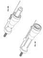
- the scooters have a tilt mode where the motor is simply tilted to a position where the drive shaft disengages the drive wheel or the transmission system of the vehicle. This is especially useful when the rider needs to temporarily stop the vehicle, e.g. in front of traffic lights.
- the rider can simply lower the motor or the drive shaft onto the drive wheel thereby engaging the drive shaft with the drive wheel. This engagement and disengagement can easily be achieved through use of a protruded steel wire and/or a spring loaded pusher or alternatively using a simple gear driven tilting mechanism.
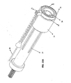
- the transmission system comprises a drive shaft (15) which is coupled by a coupling (25) to the motor shaft (12).
- the motor (11) When the motor (11) is started, the rotation of the motor shaft (12) is directly transferred to the drive shaft (15).
- the drive shaft (15) is preferably not engaged onto the drive wheel (14) that connected to the chassis of the vehicle by the hub (13).
- most of the motors for scooters or go-carts have a tilt position (see Fig. 3A, 3B , 6A, 6B , 12A, 12B , 15A, 15B ) for idling the vehicle.
- the motor is tilted so as to disengage the drive shaft from the drive wheel (14) as seen e.g. on Fig. 3A, 3B .
- the motor (11) is removed from the tilt mode and the drive shaft (15) is engaged onto the traction surface (16) of the drive wheel (14) as illustrated e.g. in Figs. 2A, 2B .
- the vehicle accelerates and gradually reaches its upper speed, which is determined by the ratio of the diameter of the drive shaft (15) and the diameter of the drive wheel (14).
- a transmission system comprises a friction element (22) for outputting higher rpm, compared to that output by the main drive shaft (15), onto the drive wheel (14).
- the friction element (22) engages to the traction surface (16) of the wheel (14) when the user pulls or triggers a shift lever (17), in result of which a metal wire (26) slides through a protrusion cable (19) and pulls a roll bearing (20) attached at the outer end of the said friction element (22).
- the roll bearing (20) is typically in the form of a ball bearing having inner ring (31) and an outer ring (32).
- the inner ring (31) is fixedly attached to the outer end of the friction element (22) and rotates with the rotation of the friction element or eventually the drive shaft (15).
- a stopper (21) is fixedly attached at any desired location on the periphery of the outer ring (32).
- the amount of displacement of the metal wire (26) inside the protrusion cable (19) equals to the amount of the displacement of the friction element (22) on the primary axis of the drive shaft (15).
- the friction element (22) has projections (30) along its inner surface that fit to corresponding grooves (24) drilled on the drive shaft (15) in order to the guide the friction element (22) along the drive shaft (15) axially.
- the metal wire (26) should have a maximum length that prevents the friction element from falling off the drive shaft (15).
- the metal wire (26) passes through a protruder (18) which is preferably a rigid pipe that avoids bending or sagging.
- a spring (23) is located in between the protruder (18) and the stopper (21) that is fixedly attached onto the roll bearing (20).
- the metal wire (26) is attached to the stopper (21) so as to move the friction element (22) back and forth along the primary axis of the drive shaft (15) depending on the choice of the user.
- the spring (23) primarily serves the purpose of preventing the friction element to unintentionally slide inwards and shift the transmission. Hence, it may be preferable to preload the spring (23) during installation to safely keep the friction element (22) in place at times the user does not pull the shift lever (17).
- the spring (23) is preferably set to push the friction element (22) towards the outer end of the drive shaft (15) so as the disengage friction element (22) when the shift lever (17) is released by the rider.
- this first embodiment of the present invention can be considered as a two shift transmission, one for high speed and one for low speed.
- the user can easily start the engine while in the tilted mode and then switch to the ride mode by way of engaging the drive shaft onto the wheel(s) after which he/she can readily and then can put the engine in the tilt mode during ride and finally pull or trigger the shift lever (17) to attain a higher speed upon engaging the friction element (22) rather than the drive shaft (15) onto the traction surface (16) of the drive wheel (14).
- the inner ring (31) of the roll bearing (20) As the inner ring (31) of the roll bearing (20) is fixedly attached to the friction element (22), they move inwards when the user pulls the shift lever (17) and engages the friction element onto the traction surface (16) of the drive wheel (14).
- the inner ring (31) shall have an inner diameter that is larger than the outer diameter of the drive shaft (15).
- the inner diameter of the inner ring (31) is slightly larger than the inner diameter of the friction element (22) and the outer diameter of the outer ring (32) is slightly smaller than the outer diameter of the friction element (22) as seen on Fig: 10 .
- the friction element (22) has a conical transition zone (27).
- the friction element (22) has smooth circular zones at both ends of the conical transition zone (27).
- This zone (27) helps to switch the friction element in between its smooth circular zones at both sides.
- the transmission system has now three stages, i.e. the first being only the drive shaft on engagement with the drive wheel, the second being the smooth zone on the left and the third being the smooth zone on the right of the conical zone (27).
- the shift lever (17) apparently has three stages.
- conical zone (27) of the friction element is adjusted to contact the surface of the drive wheel, a continuously variable speed transmission having a shift ratio in between those set by the circular zones at both sides can be achieved.
- Use of a conical or stepped friction element eliminates the possibility of excessive tire wear that might originate from the presence of grooves on the drive shaft.
- the grooves (24) drilled on the drive shaft will help a better grip of the draft shaft (15) with the traction surface (16) of the drive wheel. While it is true that these grooves may result in an increased wear on the tire, it may still be preferable have similar longitudinal grooves on the outer surfaces of the friction element (22) if the user frequently rides on slippery surfaces.
- outer surface of the drive shaft (15) and/or the friction element (22) may be provided with recesses (not shown) having a depth typically smaller than a few millimeters. Likewise, small projections of the same size may serve the same purpose. These projections and/or recesses may be machined to the periphery of the drive shaft (15) longitudinally either at an acute angle or in parallel formation to the guiding grooves (24).
Claims (13)
- Système de transmission à entraînement direct comprenant un arbre d'entraînement (15) adapté pour être accouplé par l'intermédiaire d'un accouplement (25) à son extrémité interne à un arbre de moteur (12), un élément de friction (22) qui tourne avec la rotation de l'arbre d'entraînement et qui peut être actionné longitudinalement pendant une rotation sur l'axe principal dudit arbre d'entraînement, et une butée (21), caractérisé en ce que le système comprend en outre :un roulement à rouleaux (20) comprenant au moins une bague interne (31) et une bague externe (32), ledit roulement à rouleaux étant fixé fixement autour d'au moins une partie de la périphérie de sa bague interne (31) à une extrémité dudit élément de friction (22) et où ladite bague interne (31) a un diamètre intérieur qui est supérieur au diamètre extérieur dudit arbre d'entraînement (15),dans lequel ladite butée (21) est fixée fixement à la bague externe (32) dudit roulement à rouleaux (20) et ladite butée est adaptée pour fixer un câble (26), lequel, lorsqu'il est tiré, déplace longitudinalement ledit élément de friction (22) vers l'extrémité interne dudit arbre d'entraînement (15) de manière à permettre une mise en prise dudit élément de friction avec une surface de traction (16) d'une roue d'entraînement (14).
- Système de transmission à entraînement direct selon la revendication 1, dans lequel l'élément de friction (22) est guidé sur ledit arbre d'entraînement (15) au moyen de rainures (24) et de protubérances (30) correspondantes situées longitudinalement sur ledit arbre d'entraînement et la surface intérieure dudit élément de friction.
- Système de transmission à entraînement direct selon la revendication 1, dans lequel ledit élément de friction (22) comporte une zone conique (27).
- Système de transmission à entraînement direct selon la revendication 1, dans lequel le système comprend en outre un câble saillant (19) fixé à un levier de changement de vitesse (17) adapté pour déterminer l'emplacement longitudinal dudit élément de friction (22).
- Système de transmission à entraînement direct selon la revendication 4, dans lequel le système comprend en outre un élément saillant (18) qui empêche le fléchissement du câble (26).
- Système de transmission à entraînement direct selon la revendication 5, dans lequel le système comprend en outre un ressort (23) situé entre l'élément saillant (18) et la butée (21) de manière à empêcher le coulissement involontaire de l'élément de friction (22) vers l'intérieur et le décalage de la transmission.
- Système de transmission à entraînement direct selon la revendication 6, dans lequel ledit ressort (23) est préchargé avant son installation de sorte qu'il pousse ledit élément de friction (22) vers l'extrémité externe de l'arbre d'entraînement (15) de manière à désengager l'élément de friction (22) lorsque le levier de changement de vitesse (17) est relâché par l'utilisateur.
- Système de transmission à entraînement direct selon l'une quelconque des revendications précédentes, dans lequel ledit roulement à rouleaux (20) est un roulement à billes.
- Système de transmission à entraînement direct selon l'une quelconque des revendications précédentes, dans lequel le diamètre externe dudit roulement à rouleaux (20) est inférieur au diamètre externe dudit élément de friction (22).
- Système de transmission à entraînement direct selon l'une quelconque des revendications précédentes, dans lequel l'élément de friction (22) est pourvu de protubérances et/ou d'évidements usinés longitudinalement autour de la périphérie de l'arbre d'entraînement, soit selon un angle aigu, soit en une formation parallèle à l'axe principal dudit élément de friction.
- Système de transmission à entraînement direct selon l'une quelconque des revendications précédentes, dans lequel l'arbre d'entraînement (15) est pourvu de protubérances et/ou d'évidements usinés longitudinalement autour de la périphérie de l'arbre d'entraînement, soit selon un angle aigu, soit en une formation parallèle aux rainures de guidage (24).
- Système de transmission à entraînement direct selon la revendication 1, dans lequel ledit élément de friction (22) comporte au moins deux étages de différents diamètres.
- Véhicule, en particulier un scooter, un kart ou une motocyclette, équipé du système de transmission à entraînement direct selon l'une quelconque des revendications précédentes.
Applications Claiming Priority (1)
| Application Number | Priority Date | Filing Date | Title |
|---|---|---|---|
| PCT/EP2006/069220 WO2008064723A1 (fr) | 2006-12-01 | 2006-12-01 | Transmission directe à vitesse variable |
Publications (2)
| Publication Number | Publication Date |
|---|---|
| EP1999007A1 EP1999007A1 (fr) | 2008-12-10 |
| EP1999007B1 true EP1999007B1 (fr) | 2009-10-28 |
Family
ID=38617926
Family Applications (1)
| Application Number | Title | Priority Date | Filing Date |
|---|---|---|---|
| EP06830287A Active EP1999007B1 (fr) | 2006-12-01 | 2006-12-01 | Transmission directe à vitesse variable |
Country Status (12)
| Country | Link |
|---|---|
| US (1) | US8357072B2 (fr) |
| EP (1) | EP1999007B1 (fr) |
| JP (1) | JP4874388B2 (fr) |
| KR (1) | KR101023431B1 (fr) |
| CN (1) | CN101400566B (fr) |
| AT (1) | ATE446898T1 (fr) |
| AU (1) | AU2006351171B2 (fr) |
| CA (1) | CA2656638C (fr) |
| DE (1) | DE602006010113D1 (fr) |
| EA (1) | EA014217B1 (fr) |
| ES (1) | ES2335810T3 (fr) |
| WO (1) | WO2008064723A1 (fr) |
Families Citing this family (9)
| Publication number | Priority date | Publication date | Assignee | Title |
|---|---|---|---|---|
| JP4628484B1 (ja) * | 2010-01-26 | 2011-02-09 | キロニー産業株式会社 | 自動二輪車用駆動装置及び該駆動装置を備えた自動二輪車 |
| DK2447145T3 (da) * | 2010-10-29 | 2014-04-07 | Guenther Hirn | Elektrisk drivsystem til en cykel |
| CN103991507A (zh) * | 2014-04-25 | 2014-08-20 | 杜程置 | 卡轮传动摩托车 |
| US20160255934A1 (en) * | 2015-03-02 | 2016-09-08 | Paul Attebery | Luggage Having Electrical Generator |
| CN105197176B (zh) * | 2015-10-09 | 2018-01-09 | 谢龙飞 | 电动代步车的压力传动装置 |
| US10279865B2 (en) * | 2016-08-08 | 2019-05-07 | Shareroller Llc. | Friction drive with speed wheel and automatic traction control |
| RU2685106C1 (ru) * | 2018-03-13 | 2019-04-16 | Игнат Игоревич Иванов | Передача |
| RU2684539C1 (ru) * | 2018-03-13 | 2019-04-09 | Игнат Игоревич Иванов | Передача |
| CN110131373B (zh) * | 2019-06-10 | 2023-07-28 | 中邮科技股份有限公司 | 一种转盘或转环驱动装置及驱动方法 |
Family Cites Families (35)
| Publication number | Priority date | Publication date | Assignee | Title |
|---|---|---|---|---|
| DE934657C (de) * | 1941-04-11 | 1955-12-01 | Mueller C H F Ag | Kabelendverbindung fuer Hochspannungskabel |
| DE834657C (de) * | 1950-04-12 | 1952-03-24 | App Control Equip Moteurs | Selbsttaetiges Geschwindigkeitswechselgetriebe fuer Leichtfahrzeuge, wie Fahrraeder mit Hilfsmotor od. dgl. |
| DE896433C (de) | 1950-10-30 | 1953-11-12 | Carlo Gilardi | Motor, welcher unterhalb der Pedalachse eines Fahrrades angebracht werden kann |
| FR1031966A (fr) | 1951-02-02 | 1953-06-29 | Perfectionnement aux moteurs auxiliaires pour cycles, à entraînement par galet | |
| US3781380A (en) | 1971-08-16 | 1973-12-25 | Ford Motor Co | Powder coating compositions containing glycidyl ester copolymers,carboxy terminated polymeric crosslinking agents,and flow control agents |
| US3891044A (en) * | 1973-11-07 | 1975-06-24 | Clair L Tiede | Bicycle propelling means |
| JPS5545933Y2 (fr) * | 1975-06-02 | 1980-10-28 | ||
| US4081048A (en) * | 1975-07-25 | 1978-03-28 | Hendricks William E | Automatic torque sensor |
| JPS6022221B2 (ja) * | 1978-01-17 | 1985-05-31 | 川崎重工業株式会社 | 自動変速装置 |
| US4418784A (en) * | 1982-01-26 | 1983-12-06 | Duke Fox | Bicycle transmission assembly |
| JPS59188340A (ja) * | 1983-04-06 | 1984-10-25 | 東京電力株式会社 | 系統電圧安定化装置 |
| JPS59188340U (ja) * | 1983-05-31 | 1984-12-13 | 三菱農機株式会社 | トランスミツシヨンケ−スのカバ−装置 |
| GB8332849D0 (en) | 1983-12-08 | 1984-01-18 | Searle R J | Power propelled/assisted vehicles |
| AT378753B (de) | 1984-01-25 | 1985-09-25 | Stelzer Klaus | Reibrollenantrieb fuer raeder, insbesondere fahrraeder |
| BE1002860A7 (nl) | 1989-06-26 | 1991-07-02 | Meulebroecke Maurits Van De | Elektrische fiets met adequate energie-dimensionering. |
| US5237263A (en) | 1991-06-17 | 1993-08-17 | Gannon Henry M | Electric and pedal driven bicycle with solar charging |
| DE9205672U1 (fr) | 1992-04-27 | 1992-09-03 | Hofberger, Wilfried, Dr., 3500 Kassel, De | |
| DE4219763A1 (de) | 1992-06-17 | 1993-12-23 | Ulrich Baumann | Motor-Antrieb für ein Fahrrad o. dgl. |
| US5494128A (en) * | 1993-10-13 | 1996-02-27 | Patmont Motor Werks | Fluid coupling for small engine with direct wheel drive |
| US5423393A (en) * | 1993-11-12 | 1995-06-13 | Felt; Robert M. | Auxiliary engine assembly for a bicycle |
| JPH0937417A (ja) * | 1995-07-19 | 1997-02-07 | Tokyo R & D:Kk | 電気自転車用モータ・スリップ防止装置 |
| US5660242A (en) | 1995-11-21 | 1997-08-26 | Patmont Motor Werks | Self starting and braking clutch for fluid coupling for small engine with direct wheel drive |
| JPH09207861A (ja) * | 1996-01-30 | 1997-08-12 | Kimura Haruo | 電動自転車 |
| US6102148A (en) * | 1998-10-21 | 2000-08-15 | Chien; Hsi-Hai | Electrically powered bicycle driving mechanism |
| GB9904272D0 (en) * | 1999-02-24 | 1999-04-21 | Sinclair Res Ltd | Drive apparatus for a cycle |
| US6394213B1 (en) * | 2000-07-05 | 2002-05-28 | Shui-Te Tsai | Power clutch mechanism of scooter |
| JP4669110B2 (ja) * | 2000-07-12 | 2011-04-13 | 大越 久雄 | 平行二軸駆動装置 |
| US6524214B1 (en) * | 2000-12-27 | 2003-02-25 | James A. Cillessen | Variable ratio transmission |
| US20040055803A1 (en) * | 2002-09-24 | 2004-03-25 | Patmont Motor Werks | Variable speed transmission for scooter |
| TW587582U (en) * | 2003-06-11 | 2004-05-11 | Razor Usa Llc | Driving structure for manpower vehicle |
| CN2665001Y (zh) * | 2003-12-11 | 2004-12-22 | 刘志宏 | 自行车电动器 |
| FR2892080B1 (fr) * | 2005-10-19 | 2009-04-24 | France Reducteurs Sas Soc Par | Transmission, notamment entre un arbre moteur et un arbre d'entrainement de roues d'un engin, de preference automoteur, et engin de preference automoteur equipe d'une telle transmission |
| US7394165B2 (en) * | 2005-10-22 | 2008-07-01 | Jay Schiller | Luggage with power supply circuit |
| US7665377B2 (en) * | 2005-12-09 | 2010-02-23 | Steven Harrelson | Cone and idler continuously variable transmission |
| FR2918034B3 (fr) * | 2007-06-26 | 2011-10-28 | Yvan Philippe Gilles Pesenti | Assistance thermique pour velo. |
-
2006
- 2006-12-01 US US12/097,396 patent/US8357072B2/en not_active Expired - Fee Related
- 2006-12-01 JP JP2009503429A patent/JP4874388B2/ja not_active Expired - Fee Related
- 2006-12-01 ES ES06830287T patent/ES2335810T3/es active Active
- 2006-12-01 AU AU2006351171A patent/AU2006351171B2/en not_active Ceased
- 2006-12-01 KR KR1020097001212A patent/KR101023431B1/ko active IP Right Grant
- 2006-12-01 EP EP06830287A patent/EP1999007B1/fr active Active
- 2006-12-01 WO PCT/EP2006/069220 patent/WO2008064723A1/fr active Application Filing
- 2006-12-01 EA EA200900153A patent/EA014217B1/ru not_active IP Right Cessation
- 2006-12-01 DE DE602006010113T patent/DE602006010113D1/de active Active
- 2006-12-01 CN CN2006800538094A patent/CN101400566B/zh not_active Expired - Fee Related
- 2006-12-01 CA CA2656638A patent/CA2656638C/fr not_active Expired - Fee Related
- 2006-12-01 AT AT06830287T patent/ATE446898T1/de not_active IP Right Cessation
Also Published As
| Publication number | Publication date |
|---|---|
| ATE446898T1 (de) | 2009-11-15 |
| AU2006351171B2 (en) | 2010-05-20 |
| KR101023431B1 (ko) | 2011-03-25 |
| ES2335810T3 (es) | 2010-04-05 |
| CA2656638A1 (fr) | 2008-06-05 |
| JP4874388B2 (ja) | 2012-02-15 |
| CN101400566B (zh) | 2011-08-24 |
| WO2008064723A1 (fr) | 2008-06-05 |
| EA200900153A1 (ru) | 2009-04-28 |
| EA014217B1 (ru) | 2010-10-29 |
| CA2656638C (fr) | 2011-06-14 |
| KR20090056965A (ko) | 2009-06-03 |
| JP2009532638A (ja) | 2009-09-10 |
| US8357072B2 (en) | 2013-01-22 |
| US20120065021A1 (en) | 2012-03-15 |
| DE602006010113D1 (de) | 2009-12-10 |
| EP1999007A1 (fr) | 2008-12-10 |
| CN101400566A (zh) | 2009-04-01 |
| AU2006351171A1 (en) | 2008-06-05 |
Similar Documents
| Publication | Publication Date | Title |
|---|---|---|
| EP1999007B1 (fr) | Transmission directe à vitesse variable | |
| EP1669270B1 (fr) | Dispositif et méthode de commande pour boîte de vitesses d'un véhicule du type à selle | |
| US20080312013A1 (en) | Belt Continuously Variable Transmission for Straddle Type Vehicle, and Straddle Type Vehicle | |
| US6705446B2 (en) | Automatic clutch with manual override control mechanism | |
| EP2063141B1 (fr) | Véhicule avec embrayage à friction | |
| JPS59222658A (ja) | 車両用vベルト式自動無段変速機 | |
| EP2653743A1 (fr) | Motocyclette comprenant un embrayage centrifuge | |
| EP1910715B1 (fr) | Ensemble poulie avec embrayage ameliore pour transmission a changement de vitesses continu | |
| EP2063142B1 (fr) | Embrayage à friction | |
| CN113859419A (zh) | 一种可自动换挡的三速中置电机 | |
| US9841088B2 (en) | Continuously variable transmission | |
| WO2009113104A2 (fr) | Système de transmission hybride automatique | |
| JP4176168B2 (ja) | 遠心クラッチ | |
| JP2543446B2 (ja) | 自転車 | |
| JP4998736B2 (ja) | 自動二輪車の自動変速機制御装置 | |
| CN216232802U (zh) | 一种可自动换挡的三速中置电机 | |
| JP7375993B1 (ja) | 2段変速機 | |
| JP5003899B2 (ja) | 自動二輪車の自動変速機制御装置 | |
| US20050284726A1 (en) | Centrifugally engaged drive sprocket assembly | |
| JP2009144912A (ja) | 摩擦クラッチおよびそれを備えた車両 | |
| KR0183076B1 (ko) | 자동차 내연기관용 플라이휘일의 관성력 조정장치 | |
| CN202707858U (zh) | 楔块摩擦离合器 | |
| JPH07108975A (ja) | 補助モータ付自転車用伝動装置 | |
| KR19980040160A (ko) | 후륜 구동 차량용 보조 구동 장치 | |
| JPS60136654A (ja) | 動力伝達装置 |
Legal Events
| Date | Code | Title | Description |
|---|---|---|---|
| PUAI | Public reference made under article 153(3) epc to a published international application that has entered the european phase |
Free format text: ORIGINAL CODE: 0009012 |
|
| 17P | Request for examination filed |
Effective date: 20080704 |
|
| AK | Designated contracting states |
Kind code of ref document: A1 Designated state(s): AT BE BG CH CY CZ DE DK EE ES FI FR GB GR HU IE IS IT LI LT LU LV MC NL PL PT RO SE SI SK TR |
|
| AX | Request for extension of the european patent |
Extension state: AL BA HR MK RS |
|
| GRAP | Despatch of communication of intention to grant a patent |
Free format text: ORIGINAL CODE: EPIDOSNIGR1 |
|
| GRAS | Grant fee paid |
Free format text: ORIGINAL CODE: EPIDOSNIGR3 |
|
| DAX | Request for extension of the european patent (deleted) | ||
| GRAA | (expected) grant |
Free format text: ORIGINAL CODE: 0009210 |
|
| AK | Designated contracting states |
Kind code of ref document: B1 Designated state(s): AT BE BG CH CY CZ DE DK EE ES FI FR GB GR HU IE IS IT LI LT LU LV MC NL PL PT RO SE SI SK TR |
|
| REG | Reference to a national code |
Ref country code: GB Ref legal event code: FG4D |
|
| REG | Reference to a national code |
Ref country code: CH Ref legal event code: EP |
|
| REG | Reference to a national code |
Ref country code: IE Ref legal event code: FG4D |
|
| REF | Corresponds to: |
Ref document number: 602006010113 Country of ref document: DE Date of ref document: 20091210 Kind code of ref document: P |
|
| LTIE | Lt: invalidation of european patent or patent extension |
Effective date: 20091028 |
|
| REG | Reference to a national code |
Ref country code: ES Ref legal event code: FG2A Ref document number: 2335810 Country of ref document: ES Kind code of ref document: T3 |
|
| PG25 | Lapsed in a contracting state [announced via postgrant information from national office to epo] |
Ref country code: LT Free format text: LAPSE BECAUSE OF FAILURE TO SUBMIT A TRANSLATION OF THE DESCRIPTION OR TO PAY THE FEE WITHIN THE PRESCRIBED TIME-LIMIT Effective date: 20091028 Ref country code: FI Free format text: LAPSE BECAUSE OF FAILURE TO SUBMIT A TRANSLATION OF THE DESCRIPTION OR TO PAY THE FEE WITHIN THE PRESCRIBED TIME-LIMIT Effective date: 20091028 Ref country code: PT Free format text: LAPSE BECAUSE OF FAILURE TO SUBMIT A TRANSLATION OF THE DESCRIPTION OR TO PAY THE FEE WITHIN THE PRESCRIBED TIME-LIMIT Effective date: 20100301 Ref country code: SE Free format text: LAPSE BECAUSE OF FAILURE TO SUBMIT A TRANSLATION OF THE DESCRIPTION OR TO PAY THE FEE WITHIN THE PRESCRIBED TIME-LIMIT Effective date: 20091028 Ref country code: IS Free format text: LAPSE BECAUSE OF FAILURE TO SUBMIT A TRANSLATION OF THE DESCRIPTION OR TO PAY THE FEE WITHIN THE PRESCRIBED TIME-LIMIT Effective date: 20100228 |
|
| PG25 | Lapsed in a contracting state [announced via postgrant information from national office to epo] |
Ref country code: SI Free format text: LAPSE BECAUSE OF FAILURE TO SUBMIT A TRANSLATION OF THE DESCRIPTION OR TO PAY THE FEE WITHIN THE PRESCRIBED TIME-LIMIT Effective date: 20091028 Ref country code: PL Free format text: LAPSE BECAUSE OF FAILURE TO SUBMIT A TRANSLATION OF THE DESCRIPTION OR TO PAY THE FEE WITHIN THE PRESCRIBED TIME-LIMIT Effective date: 20091028 Ref country code: CY Free format text: LAPSE BECAUSE OF FAILURE TO SUBMIT A TRANSLATION OF THE DESCRIPTION OR TO PAY THE FEE WITHIN THE PRESCRIBED TIME-LIMIT Effective date: 20091028 Ref country code: LV Free format text: LAPSE BECAUSE OF FAILURE TO SUBMIT A TRANSLATION OF THE DESCRIPTION OR TO PAY THE FEE WITHIN THE PRESCRIBED TIME-LIMIT Effective date: 20091028 |
|
| PG25 | Lapsed in a contracting state [announced via postgrant information from national office to epo] |
Ref country code: BE Free format text: LAPSE BECAUSE OF FAILURE TO SUBMIT A TRANSLATION OF THE DESCRIPTION OR TO PAY THE FEE WITHIN THE PRESCRIBED TIME-LIMIT Effective date: 20091028 Ref country code: AT Free format text: LAPSE BECAUSE OF FAILURE TO SUBMIT A TRANSLATION OF THE DESCRIPTION OR TO PAY THE FEE WITHIN THE PRESCRIBED TIME-LIMIT Effective date: 20091028 |
|
| PG25 | Lapsed in a contracting state [announced via postgrant information from national office to epo] |
Ref country code: EE Free format text: LAPSE BECAUSE OF FAILURE TO SUBMIT A TRANSLATION OF THE DESCRIPTION OR TO PAY THE FEE WITHIN THE PRESCRIBED TIME-LIMIT Effective date: 20091028 Ref country code: DK Free format text: LAPSE BECAUSE OF FAILURE TO SUBMIT A TRANSLATION OF THE DESCRIPTION OR TO PAY THE FEE WITHIN THE PRESCRIBED TIME-LIMIT Effective date: 20091028 Ref country code: BG Free format text: LAPSE BECAUSE OF FAILURE TO SUBMIT A TRANSLATION OF THE DESCRIPTION OR TO PAY THE FEE WITHIN THE PRESCRIBED TIME-LIMIT Effective date: 20100128 Ref country code: RO Free format text: LAPSE BECAUSE OF FAILURE TO SUBMIT A TRANSLATION OF THE DESCRIPTION OR TO PAY THE FEE WITHIN THE PRESCRIBED TIME-LIMIT Effective date: 20091028 Ref country code: MC Free format text: LAPSE BECAUSE OF NON-PAYMENT OF DUE FEES Effective date: 20100701 |
|
| PG25 | Lapsed in a contracting state [announced via postgrant information from national office to epo] |
Ref country code: CZ Free format text: LAPSE BECAUSE OF FAILURE TO SUBMIT A TRANSLATION OF THE DESCRIPTION OR TO PAY THE FEE WITHIN THE PRESCRIBED TIME-LIMIT Effective date: 20091028 Ref country code: SK Free format text: LAPSE BECAUSE OF FAILURE TO SUBMIT A TRANSLATION OF THE DESCRIPTION OR TO PAY THE FEE WITHIN THE PRESCRIBED TIME-LIMIT Effective date: 20091028 |
|
| PLBE | No opposition filed within time limit |
Free format text: ORIGINAL CODE: 0009261 |
|
| STAA | Information on the status of an ep patent application or granted ep patent |
Free format text: STATUS: NO OPPOSITION FILED WITHIN TIME LIMIT |
|
| 26N | No opposition filed |
Effective date: 20100729 |
|
| PG25 | Lapsed in a contracting state [announced via postgrant information from national office to epo] |
Ref country code: GR Free format text: LAPSE BECAUSE OF FAILURE TO SUBMIT A TRANSLATION OF THE DESCRIPTION OR TO PAY THE FEE WITHIN THE PRESCRIBED TIME-LIMIT Effective date: 20100129 Ref country code: IE Free format text: LAPSE BECAUSE OF NON-PAYMENT OF DUE FEES Effective date: 20091201 |
|
| PG25 | Lapsed in a contracting state [announced via postgrant information from national office to epo] |
Ref country code: LU Free format text: LAPSE BECAUSE OF NON-PAYMENT OF DUE FEES Effective date: 20091201 |
|
| PG25 | Lapsed in a contracting state [announced via postgrant information from national office to epo] |
Ref country code: HU Free format text: LAPSE BECAUSE OF FAILURE TO SUBMIT A TRANSLATION OF THE DESCRIPTION OR TO PAY THE FEE WITHIN THE PRESCRIBED TIME-LIMIT Effective date: 20100429 |
|
| REG | Reference to a national code |
Ref country code: CH Ref legal event code: PL |
|
| PG25 | Lapsed in a contracting state [announced via postgrant information from national office to epo] |
Ref country code: CH Free format text: LAPSE BECAUSE OF NON-PAYMENT OF DUE FEES Effective date: 20101231 Ref country code: LI Free format text: LAPSE BECAUSE OF NON-PAYMENT OF DUE FEES Effective date: 20101231 |
|
| REG | Reference to a national code |
Ref country code: FR Ref legal event code: PLFP Year of fee payment: 10 |
|
| PGFP | Annual fee paid to national office [announced via postgrant information from national office to epo] |
Ref country code: ES Payment date: 20151216 Year of fee payment: 10 Ref country code: NL Payment date: 20151217 Year of fee payment: 10 |
|
| REG | Reference to a national code |
Ref country code: FR Ref legal event code: PLFP Year of fee payment: 11 |
|
| REG | Reference to a national code |
Ref country code: NL Ref legal event code: MM Effective date: 20170101 |
|
| PG25 | Lapsed in a contracting state [announced via postgrant information from national office to epo] |
Ref country code: NL Free format text: LAPSE BECAUSE OF NON-PAYMENT OF DUE FEES Effective date: 20170101 |
|
| REG | Reference to a national code |
Ref country code: FR Ref legal event code: PLFP Year of fee payment: 12 |
|
| PGFP | Annual fee paid to national office [announced via postgrant information from national office to epo] |
Ref country code: DE Payment date: 20171218 Year of fee payment: 12 |
|
| PG25 | Lapsed in a contracting state [announced via postgrant information from national office to epo] |
Ref country code: ES Free format text: LAPSE BECAUSE OF NON-PAYMENT OF DUE FEES Effective date: 20161202 |
|
| PGFP | Annual fee paid to national office [announced via postgrant information from national office to epo] |
Ref country code: IT Payment date: 20171221 Year of fee payment: 12 |
|
| REG | Reference to a national code |
Ref country code: ES Ref legal event code: FD2A Effective date: 20181122 |
|
| PGFP | Annual fee paid to national office [announced via postgrant information from national office to epo] |
Ref country code: GB Payment date: 20181217 Year of fee payment: 13 Ref country code: FR Payment date: 20181214 Year of fee payment: 13 |
|
| REG | Reference to a national code |
Ref country code: DE Ref legal event code: R119 Ref document number: 602006010113 Country of ref document: DE |
|
| PG25 | Lapsed in a contracting state [announced via postgrant information from national office to epo] |
Ref country code: DE Free format text: LAPSE BECAUSE OF NON-PAYMENT OF DUE FEES Effective date: 20190702 Ref country code: IT Free format text: LAPSE BECAUSE OF NON-PAYMENT OF DUE FEES Effective date: 20181201 |
|
| GBPC | Gb: european patent ceased through non-payment of renewal fee |
Effective date: 20191201 |
|
| PG25 | Lapsed in a contracting state [announced via postgrant information from national office to epo] |
Ref country code: FR Free format text: LAPSE BECAUSE OF NON-PAYMENT OF DUE FEES Effective date: 20191231 Ref country code: GB Free format text: LAPSE BECAUSE OF NON-PAYMENT OF DUE FEES Effective date: 20191201 |
|
| PGFP | Annual fee paid to national office [announced via postgrant information from national office to epo] |
Ref country code: TR Payment date: 20231127 Year of fee payment: 18 |