EP1998145A2 - Mikrosensor zum Erfassen einer Entfernungsänderung oder eines Zyklus von Entfernungsänderungen zwischen zwei Punkten oder Zonen einer Struktur bei Belastung - Google Patents
Mikrosensor zum Erfassen einer Entfernungsänderung oder eines Zyklus von Entfernungsänderungen zwischen zwei Punkten oder Zonen einer Struktur bei Belastung Download PDFInfo
- Publication number
- EP1998145A2 EP1998145A2 EP08290493A EP08290493A EP1998145A2 EP 1998145 A2 EP1998145 A2 EP 1998145A2 EP 08290493 A EP08290493 A EP 08290493A EP 08290493 A EP08290493 A EP 08290493A EP 1998145 A2 EP1998145 A2 EP 1998145A2
- Authority
- EP
- European Patent Office
- Prior art keywords
- support
- tooth
- toothed wheel
- parts
- gear
- Prior art date
- Legal status (The legal status is an assumption and is not a legal conclusion. Google has not performed a legal analysis and makes no representation as to the accuracy of the status listed.)
- Granted
Links
Images


Classifications
-
- G—PHYSICS
- G01—MEASURING; TESTING
- G01D—MEASURING NOT SPECIALLY ADAPTED FOR A SPECIFIC VARIABLE; ARRANGEMENTS FOR MEASURING TWO OR MORE VARIABLES NOT COVERED IN A SINGLE OTHER SUBCLASS; TARIFF METERING APPARATUS; MEASURING OR TESTING NOT OTHERWISE PROVIDED FOR
- G01D1/00—Measuring arrangements giving results other than momentary value of variable, of general application
- G01D1/04—Measuring arrangements giving results other than momentary value of variable, of general application giving integrated values
-
- G—PHYSICS
- G01—MEASURING; TESTING
- G01B—MEASURING LENGTH, THICKNESS OR SIMILAR LINEAR DIMENSIONS; MEASURING ANGLES; MEASURING AREAS; MEASURING IRREGULARITIES OF SURFACES OR CONTOURS
- G01B5/00—Measuring arrangements characterised by the use of mechanical techniques
- G01B5/30—Measuring arrangements characterised by the use of mechanical techniques for measuring the deformation in a solid, e.g. mechanical strain gauge
-
- G—PHYSICS
- G01—MEASURING; TESTING
- G01D—MEASURING NOT SPECIALLY ADAPTED FOR A SPECIFIC VARIABLE; ARRANGEMENTS FOR MEASURING TWO OR MORE VARIABLES NOT COVERED IN A SINGLE OTHER SUBCLASS; TARIFF METERING APPARATUS; MEASURING OR TESTING NOT OTHERWISE PROVIDED FOR
- G01D5/00—Mechanical means for transferring the output of a sensing member; Means for converting the output of a sensing member to another variable where the form or nature of the sensing member does not constrain the means for converting; Transducers not specially adapted for a specific variable
- G01D5/02—Mechanical means for transferring the output of a sensing member; Means for converting the output of a sensing member to another variable where the form or nature of the sensing member does not constrain the means for converting; Transducers not specially adapted for a specific variable using mechanical means
- G01D5/04—Mechanical means for transferring the output of a sensing member; Means for converting the output of a sensing member to another variable where the form or nature of the sensing member does not constrain the means for converting; Transducers not specially adapted for a specific variable using mechanical means using levers; using cams; using gearing
-
- G—PHYSICS
- G06—COMPUTING OR CALCULATING; COUNTING
- G06M—COUNTING MECHANISMS; COUNTING OF OBJECTS NOT OTHERWISE PROVIDED FOR
- G06M1/00—Design features of general application
- G06M1/04—Design features of general application for driving the stage of lowest order
- G06M1/041—Design features of general application for driving the stage of lowest order for drum-type indicating means
-
- G—PHYSICS
- G01—MEASURING; TESTING
- G01D—MEASURING NOT SPECIALLY ADAPTED FOR A SPECIFIC VARIABLE; ARRANGEMENTS FOR MEASURING TWO OR MORE VARIABLES NOT COVERED IN A SINGLE OTHER SUBCLASS; TARIFF METERING APPARATUS; MEASURING OR TESTING NOT OTHERWISE PROVIDED FOR
- G01D2205/00—Indexing scheme relating to details of means for transferring or converting the output of a sensing member
- G01D2205/10—Detecting linear movement
- G01D2205/14—Detecting linear movement by converting the linear movement into a rotary movement
Definitions
- the present invention relates to the field of microsensors and more particularly to a microsensor capable of detecting, and preferably also counting, the number of cycles of variations in distance between two points or zones of a structure subjected to a repeated external action, for example temperature cycles or mechanical stresses such as the number of vehicle passes on a bridge, generating a known level of stress in the structure.
- the second of them concerns the impossibility of using them in complete pyrotechnic safety. Indeed, the presence of a potential difference and therefore of an electric current generates a risk of spark formation or short circuit that can cause a fire or explosion in the presence of detonating materials.
- the third of these relates to their sensitivity to magnetic fields due, in particular, to the generation of induced currents in the electrical circuits and the degradation of the electronic components that results.
- sensors and associated processing means are large, typically several tens of centimeters which makes them very visible and explains that they are subject to acts of vandalism.
- a passive and reversible sensor for deformations along a direction OX of a structure, in particular during temperature cycles or mechanical stresses to which said structure is subjected
- this sensor comprising detection means and means of counting, characterized in that it comprises means for detecting and counting cycles of variation in distance between two points or zones of a structure, these means comprising a support having a first and a second part each having a zone of anchoring, these anchoring zones being able to be respectively fixed to one and the other of said two points or zones of the structure and being constituted by studs, notches and / or bores and being of smaller dimensions than those of the first and second parts, the counting means being associated with each of said first and second parts of the support.
- this first gear is disposed on a first support or on a first part of a support and at least one drive beam is secured at one of its ends to a second support or a second support. part of said support and comprises, at its other end, at least one tooth capable of meshing with said first toothed wheel.
- the anti-return device comprises a tooth capable of meshing with said first toothed wheel, this tooth as well as that of the driving beam, and those of said toothed wheel each comprising a radial surface and an inclined surface connecting the ends of the radial surface of this tooth at the base of the radial surface of the next tooth.
- a passive detection and counting microsensor comprises a support, mainly U-shaped, thus comprising a first part and a second part connected by a third part constituting the base of the U, and counting means arranged on the support and having at least one first gear disposed on one of the first or second parts and, on the one hand, a driving beam of the toothed wheel fixed at one end to the other of first or second parts and having, at its other end, a tooth capable of constituting a gear with the teeth of the first toothed wheel, and secondly, a non-return device of the first toothed wheel and such that the approximation of the first and second parts produces a drive of the toothed wheel by the tooth of the beam of drive while the removal of these two parts produces a maintenance of the toothed wheel by the non-return device and a retraction of the tooth of the driving beam on a tooth of the first toothed wheel.
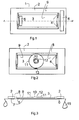
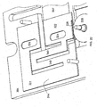
- the Figures 1 to 3 show a sensor according to one embodiment and, respectively, the lower face 7, the upper face 8 and a view according to the section AA 'of the figure 1 .
- This sensor 1 comprises a support S having a first part 2 in the form of a frame and on which is fixed a first stud 6 intended to be fixed on a structure 15 subjected to deformation cycles, in particular in tension, in compression or in flexion, for example due to mechanical and / or thermal stress.
- the support S also comprises a second part 3, also called shuttle in the following, of rectangular shape and smaller dimensions than the inside of said frame 2.
- the first and the second parts 2, 3 are secured to one another. another by four springs 4 arranged in the free space between these two parts 2, 3 and at each of the four corners of the second part 3.
- This second part 3 also comprises a second stud 5 arranged in this embodiment, the opposite side to the amount of the frame 2 which supports the first stud 6 and also intended to be fixed on said structure 15.
- the second part 3 comprises, on its upper surface, a cylindrical hub 10 integral with three blades 12 arranged tangentially to the hub 10 and around which is placed a toothed wheel 11.
- the tooth 21 of the driving beam has a drive face which comes into contact with the tooth of the counting wheel to pull the wheel during a displacement in one direction of the driving element and a guide face. allowing the sliding element, and thus the retraction, of the driving element on the tooth of the counting wheel during a displacement in the opposite direction to the preceding one of the driving element.
- the spacing between the pads varies and the points A and B are found in the extreme positions A 'and B', their coordinates then being x A ' and x B' while the pads return to their original or slightly different position at the end of the solicitation or a certain time later.
- This spacing difference between the studs 5 and 6 causes a positioning variation between the first and second parts, respectively 2 and 3.
- said positioning variation produces a drive of the toothed wheel 11 by the driving beam 20 in the direction of the arrow.
- the relative displacement of the tooth 21 of the driving beam 20 with respect to the second portion 3 is of the order of magnitude of the pitch of the teeth 16 of the toothed wheel 11, namely, once and a half larger, the toothed wheel 11 will be rotated by the tooth 21 of the driving beam 20, the respective radial faces 23 and 28 of the tooth n of the toothed wheel 11 and the tooth 21 of the driving beam 20 being in contact.
- the pads, and therefore the corresponding supports will return to their initial position but the anti-return device consisting of the blades 12 and second teeth 18 of the toothed wheel 11, prevents the toothed wheel 11 to turn in the opposite direction to that of the arrow while, due to its elasticity, the inclined face 27 of the tooth 21 of the driving beam slides on that of the tooth n + 1 of the toothed wheel 11 with which it is in contact until it reaches the top 25 of this tooth, the radial face 28 of the tooth 21 of the driving beam then being opposite the radial face 23 of the tooth n + 1 of the wheel toothed 11.
- the spacing of the studs 5 and 6, following a bias produces a drive of the toothed wheel 11 by the driving tooth 21 of the driving beam 20 while the approximation of these two parts, to the end of the bias, produces a maintenance of the first toothed wheel 11 by the non-return device 12, 19 and a retraction of the tooth 21 of the driving beam 20 on a tooth 16 of the first toothed wheel 11.
- the detection by the microsensor of a cycle of distance variations results in a rotation of the toothed wheel 11, marks associated with this wheel then making it possible to determine the number of cycles undergone by the structure from an origin, where between two given times.
- the studs can also be replaced by notches or by bores.
- each of the pads is replaced by at least one bore and preferably two bores positioned so that their diameter d is much smaller than the distance D separating their axis, for example d / D ⁇ 0.2.
- the realization of studs, notches or boring as anchoring zone makes it possible to accurately know the distance L separating the anchoring zones and thus to allow the counting of the cycles of variations in distance. between two points A and B of a structure. Knowing the characteristics of the deformation of the structure, and taking into account the pitch P of the teeth of the counting wheel, the distance L between the anchoring points is determined so that during the deformation of the structure, the variation of distance between the anchoring zones 5 and 6 is greater than the pitch P of the teeth of the counting wheel and preferably close to or equal to 1.5. P.
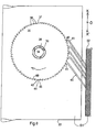
- This toothed wheel 35 has teeth 36 on its outer peripheral surface 37 and an inner peripheral surface 38 of cylindrical shape.
- the inner peripheral surface 38 of the toothed wheel 35 and the end of said blades 39 are intended to cooperate to form an elastic means of accommodation of the gear 35 on the hub 34, the friction force of the end of the blades 39 on the inner peripheral surface 38 of the wheel 35 being, on the one hand, greater than that which can cause the drive beams when they are directed in a first direction OX, then causing a sliding of the teeth 41 of the beams 40 on the wheel 35 and, on the other hand, lower than that which can be generated by the driving beams when they are in a second direction OX ', opposite to said direction OX, thus causing a sliding of the inner peripheral surface 38 of the wheel 35 on the ends of the blades 39.
- the sliding of the wheel on the ends of the blades 39 is allowed by a correct dimensioning of the elastic accommodation means of the resistant torque relative to the possible shear of the tooth 41 of the beam 40 or that, 36, of the toothed wheel 35.
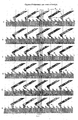
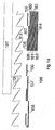
- the different phases are respectively numbered from 1 to 5 and from A to E.
- phase C the beam 5 has just crossed the teeth of the wheel and prohibits its return to another place than that of phase B. It is the same phase D and E.
- Such a device makes it possible to detect and count cycles of distance variations of less than 5 ⁇ m. By increasing the number of beams, variations of distances smaller than 1 ⁇ m can be detected and counted.
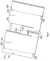
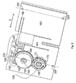
- FIGS. 8 to 18 show diagrams of a third embodiment of the invention applied to counting the number of vehicles passing on a structure, such as for example a bridge.
- the figures 8 and 9 present one and the other of the two main faces of the sensor according to this third embodiment of the invention.
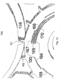
- a passive sensor for detecting and counting the number of vehicle passages comprises a support 101, mainly U-shaped, thus having a first part 102 and a second part 103 connected to each other by a third part 104. constituting the base of the U, and counting means 105 arranged on the support and comprising at least a first gear 106 disposed on said first portion 102 of the support 101 and, on the one hand, a driving beam 107 of this first toothed wheel 106 attached to one, 108, its ends 108, 109, said second portion 103 and having, at its other end 109, a tooth 110, shown on the figure 10 , and adapted to constitute a gear 111 with the teeth 112 of the first gear 106, and secondly, a non-return device 113 of the first gear 106 and such that the approximation of the first and second parts 102 , 103 of the support 101 produces a drive of the toothed wheel 106 by the driving tooth 110 of the driving beam 107 while the distance
- the deformation of the structure between the axes Y1 and Y2 must at least be equal to P and preferably lower or equal to 1.5.P.
- the faces 133, 134 and 135 of the respective portions 102, 103 and 104 of the support 101 are flat and arranged in the same plane and intended to be pressed against the structure to be analyzed via said screws.
- the third portion 104 of the support itself has an inverted U-shape with a thick base 136.
- This shape makes it possible to have smaller sections at the branches of the U of this beam than of the base 136 and in the case where a significant force was exerted at this third part a break would occur at the level of one of the branches and therefore in a direction parallel to that of the normal displacement of the first and second parts, which makes it possible to avoid any relative displacement between these parts in the normal direction of displacement and to avoid a possible offset between the toothed wheel 106 and the tooth 110 of the driving beam 107.
- each tooth 112 of this first wheel toothed 106 has a first radial surface 114 and an inclined surface 115 connecting the upper end 116 of said first radial surface to the base 117 of the radial surface of the next tooth.
- the tooth 110 secured to the driving beam 109 has an inclined surface 118 and a radial surface 119, the latter being in face to face with said first radial surface 114 of a tooth 112 of the first wheel 106 counting.
- This first gear 106 has 512 teeth, ie 2 9 .
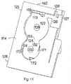
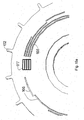
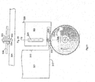
- the figure 11 shows one of the two main faces of the first portion 102 of the support adapted to receive a portion of the counting means 105.
- This surface 174 comprises several successive etchings 120, 121, 122, 123 and 124 having certain common parts.
- the first etching 120 is disposed in the upper portion 125 of the first portion and the side of the first portion 102 of the support. It has the shape of a thick-base U and one of the branches 126 is longer than the other 127.
- the second etching 121 is of elongated rectangular shape and arranged in continuity with the first and toward the side opposite to the third portion 104 of the support 101. However, this etching is not complete because there remains a non-return device 113 disposed longitudinally on less than half the length of the etching and fixed to the first portion 102 of the support 101 by its end located at the transverse side 170 of the etching which is opposite to the first etching 120.
- the third etching 122 is of cylindrical shape and arranged in the continuity of the second and below, that is to say in the direction of the lower part 128 of the first part 102 of the support 101. However, the etching is not not complete because it remains a cylindrical central portion 129.
- This etching 122 is intended to receive the first counting wheel 106 and its diameter is slightly greater than that of the latter.
- the first counting wheel 106 has a central bore and the cylindrical central portion 129 constitutes an axis for this first gear 106.
- the fifth etching 124 is cylindrical in shape with a diameter slightly smaller than that of the third etching 122 and arranged tangentially at this point. last and in the direction of the lower portion 128 of this first portion 123 of the support.
- This etching 124 is intended to receive a second counting gear 130 and is not complete because it remains on the one hand a central cylindrical portion intended to serve as axis of rotation 155 to the second counter gear 130 and d on the other hand three beams 171, 172 and 173 respectively arranged at ⁇ / 2 Rd and able to maintain in position and serve as a non-return device to the second gear wheel 30.
- the latter has 16 teeth or 2 4 .
- the driving beam 107 and that, 75, of the non-return device are flexibly preloaded on the toothed wheel 106 by their positioning. Indeed the end of the teeth is not tangential to the base of the teeth of the first gear 106 but tangential to a position located closer to the axis of the wheel, As these beams can not go beyond said base, they are automatically subjected to said preload exerted by the first gear 106.
- the figure 12 shows a detail of the intermediate portion 143 of the driving beam 107 which is at the level of the first etching 120 of the first part of the support 101.
- This intermediate portion 143 is U-shaped whose base 144, and the two branches 145, 146 have substantially the same thickness, one, 145, branches being longer than the other and intended to penetrate into the longer part of the branch 126 of the first etching of the first support 101 and which, as can be seen in this figure, comprises two stops 147, 148 each facing one side of the longer portion 149 of the branch 145 of the driving beam.
- These protrusions are to limit the displacement of the drive beam towards the first part of the support, a calibrated value and corresponding substantially to the value of a step and a half of the teeth 112 of the first gear 106.
- These excrescences thus constitute means for limiting the stroke of the tooth 110 of the driving beam 107, or, in other words, stops.
- the thickness of the driving beam beyond this intermediate portion is initially equivalent to that of this portion and then lower to its end comprising the driving tooth 110, this small thickness being adapted to provide sufficient elasticity to allow the drive gear 106 to be driven by the drive tooth 110 in a forward direction and the retraction of this drive tooth 110 to those 112 of the first gear 106 in the return direction.
- a third counting gear 150 of smaller diameter than the first gear 106 is fixed on the latter, these two wheels having the same axis of rotation.
- said axis Y1 passes through the axes of rotation of the first, second and third counting wheels as well as the axes of the bores of the first anchoring zones.
- This axis Y1 is perpendicular to the direction X of the deformations of the structure that can be detected by the microsensor on which it is fixed.
- This third counting gear wheel 150 comprises a single tooth 151 in the form of a Gothic arch capable of constituting a gear with those 152, in the form of a Roman arch, of the second counting wheel 130, these two wheels 130, 150 having the same thickness and being arranged in the same plane.
- This third gear 150 is disposed in the fourth etching 123 of the first portion 102 of the support 101 and has a bore of diameter substantially equal to the axis 155 emerging from the fourth etching.
- the length of the teeth 152 and 151 of the second and third gears 130 and 150 is such that when the tooth 51 of the third gear 150 comes into contact with a tooth 152 of the second wheel toothed 130, this contact continues over a length substantially equal to the pitch of the teeth 152 of the second gear 130.
- Bar code reader optical reading means are associated with the counting means in order to facilitate reading.
- grooves 166 arc parallel circles in this case four maximum are associated with the teeth 152 of the second gear 130 and allow to number them in a binary manner, the tooth numbered 1 having no associated groove, the tooth number 2 having a groove at a first line 167, the tooth number 3 having a groove at the second line 168, the tooth # 4 having a groove at each of the first two lines 167 and 168 etc. and until the 16 th tooth to which corresponds a groove at each of the four lines 167-170.
- parallel grooves in this case nine maximum are associated with the 512 teeth of the first gear 106 and make it possible to number them in a binary manner, the numbered tooth 1 having no associated groove, the number 2 tooth having a groove at a first line 156, the number 3 tooth having a groove at the second line 157, tooth # 4 having a groove at each of the first two lines 156 and 157, etc ... and this up to the 512th tooth which has a groove at each of the nine lines 156 to 164.
- an optical reading of the numbering of the teeth on each of the first and second gears 106 and 130 is carried out at time t0 and then at the instant t1, the reader having the same position at these two moments.
- the image of the first reading at time t0 is that of reference which makes it possible to determine which tooth was engaged at the time of installation of the device.
- the second image is used to identify the tooth engaged at time t1, chosen by the operator.
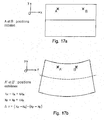
- the identification of the engaged tooth can be done automatically by importing the two images into an image processing software by generating a mask 177 delimiting the reading zones as shown in FIG. figures 15a and 15b .
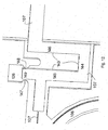
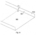
- This microsensor is positioned on the parapet on either side of a virtual straight line CD.
- the microsensor will not count the passage of the vehicle according to a threshold value corresponding to the mass of the vehicle. It will thus be possible for example to detect, with three identical sensors but arranged at different places of the parapet, the number of vehicle passing from a mass greater than 500kg for one, the number of vehicle of more than 3500kg for the second. and all vehicles over 10,000kg for each other.
- ⁇ x (x A ' -x A ) - (x B' -x B ) which is used to actuate the passive counting means, the point A being on the first portion 102 of the support 101 and the point B being on the second portion 103 of the support 101.
- ⁇ x is greater than the pitch of the teeth 112 of the first gear 106 and preferably less than 2 times this step.
- the abutments 147, 148 are able to limit the displacement of the first part of the support 101 relative to the second part by a distance ⁇ x, with respect to their rest position, greater than the pitch of the teeth 112 of the first wheel 106, but less than twice this pitch.
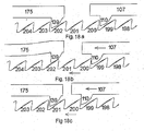
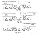
- FIGS. 18a to 18e show the evolution of the positioning of the drive tooth 110 relative to the teeth 112 of the first gear 106 for successive instants t0, t1, t2, t3 and t4, t0 and t4 corresponding to the equilibrium position and t2 , the position where the approximation between the first and second parts 102, 103 of the support 101 is maximum.
- the first and second portions 102, 103 of the support 101 are in the rest position.
- the radial face of the drive tooth 110 as well as that of the non-return device 113 are each facing a radial face of a tooth, respectively 200 and 203, of the first toothed wheel 106, the faces facing each other. not being in contact.
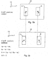
- the counting means comprises a plurality of beams capable of successively driving the toothed wheel in one and the same direction
- these beams may be arranged on the same side of the toothed wheel as on FIG. figure 6 or, for example, partly on one side and partly on the other without the operation of the device being changed.
- the teeth of said beams can be placed at the same distance from each other or at different distances while respecting the formula of the spacing E given in the description.
- the sensor supports in a material whose thermal expansion coefficient is close of that of the material of the structure, and, secondly, to compensate geometrically, via the shape of said first and second part of the support and the positioning of the counting wheel, this thermal expansion.
Landscapes
- Physics & Mathematics (AREA)
- General Physics & Mathematics (AREA)
- Engineering & Computer Science (AREA)
- Theoretical Computer Science (AREA)
- Length Measuring Devices With Unspecified Measuring Means (AREA)
- Transmission And Conversion Of Sensor Element Output (AREA)
- Gears, Cams (AREA)
- Micromachines (AREA)
Applications Claiming Priority (1)
| Application Number | Priority Date | Filing Date | Title |
|---|---|---|---|
| FR0703754A FR2916843A1 (fr) | 2007-05-29 | 2007-05-29 | Microcapteur apte a detecter une variation de distance ou un cycle de variations de distance entre deux points ou zones d'une structure lors d'une sollicitation. |
Publications (4)
| Publication Number | Publication Date |
|---|---|
| EP1998145A2 true EP1998145A2 (de) | 2008-12-03 |
| EP1998145A3 EP1998145A3 (de) | 2013-06-19 |
| EP1998145B1 EP1998145B1 (de) | 2019-03-27 |
| EP1998145B8 EP1998145B8 (de) | 2019-06-26 |
Family
ID=38935777
Family Applications (2)
| Application Number | Title | Priority Date | Filing Date |
|---|---|---|---|
| EP08290493.9A Active EP1998145B8 (de) | 2007-05-29 | 2008-05-28 | Mikrosensor zum Erfassen einer Entfernungsänderung oder eines Zyklus von Entfernungsänderungen zwischen zwei Punkten oder Zonen einer Struktur bei Belastung |
| EP08290492.1A Active EP1998144B8 (de) | 2007-05-29 | 2008-05-28 | Vorrichtung zur Übertragung einer relativen Bewegung zwischen einem zweiten und einem dritten Element eines Systems an ein erstes bewegliches Element mit Zähnen |
Family Applications After (1)
| Application Number | Title | Priority Date | Filing Date |
|---|---|---|---|
| EP08290492.1A Active EP1998144B8 (de) | 2007-05-29 | 2008-05-28 | Vorrichtung zur Übertragung einer relativen Bewegung zwischen einem zweiten und einem dritten Element eines Systems an ein erstes bewegliches Element mit Zähnen |
Country Status (4)
| Country | Link |
|---|---|
| EP (2) | EP1998145B8 (de) |
| DK (2) | DK1998144T3 (de) |
| ES (2) | ES2737424T3 (de) |
| FR (3) | FR2916843A1 (de) |
Cited By (3)
| Publication number | Priority date | Publication date | Assignee | Title |
|---|---|---|---|---|
| WO2012143627A1 (fr) | 2011-04-22 | 2012-10-26 | ÉTAT FRANÇAIS représenté par LE DÉLÉGUÉ GÉNÉRAL POUR L'ARMEMENT | Capteur passif et réversible de déformations |
| WO2017149211A1 (fr) | 2016-03-02 | 2017-09-08 | Etat Français Represente Par Le Delegue General Pour L'armement | Capteur de deformation permettant une discrimination de mesure en fonction de la direction de la deformation |
| US10654564B2 (en) | 2016-12-15 | 2020-05-19 | Safran Landing Systems Uk Ltd | Aircraft assembly including deflection sensor |
Families Citing this family (3)
| Publication number | Priority date | Publication date | Assignee | Title |
|---|---|---|---|---|
| WO2010095008A1 (en) * | 2009-02-18 | 2010-08-26 | Aktiebolaget Skf | Contactless sensor and detecting assembly comprising such a contactless sensor |
| FR3008179B1 (fr) | 2013-07-02 | 2015-06-12 | France Etat | Microcapteur passif et reversible de deformations |
| FR3025599B1 (fr) * | 2014-09-10 | 2019-05-31 | Direction Generale De L'armement -Ds/Sdpa/Bpi - Dga/Ds/Sdpa/Bpi | Procede de comptage d'evenements survenus pendant une duree t et compteurs mecaniques d'evenements associes |
Citations (3)
| Publication number | Priority date | Publication date | Assignee | Title |
|---|---|---|---|---|
| US5452335A (en) | 1992-12-31 | 1995-09-19 | Symbiosis Corporation | Temperature cycle counter |
| US6617963B1 (en) | 1999-02-26 | 2003-09-09 | Sri International | Event-recording devices with identification codes |
| FR2875324A1 (fr) | 2004-09-13 | 2006-03-17 | Parifex | Systeme de detection de passage et de comptage de vehicules a moteur |
Family Cites Families (4)
| Publication number | Priority date | Publication date | Assignee | Title |
|---|---|---|---|---|
| FR703754A (fr) | 1930-10-16 | 1931-05-06 | Manuf De Machines Modernes | Perfectionnements au montage des cylindres porte-cliché dans les machines à imprimer |
| CH497725A (de) * | 1962-01-31 | 1964-12-31 | Straumann Inst Ag | Antrieb für ein mit tonfrequenten, translatorischen Oszillationen angetriebenes Zeitmessgerät |
| FR2893139B1 (fr) * | 2005-09-13 | 2008-08-08 | France Etat | Micro capteur apte a detecter et a compter des chocs ou des accelerations/decelerations. |
| FR2890748A1 (fr) * | 2005-09-13 | 2007-03-16 | France Etat Armement | Micro capteur apte a detecter et a compter des chocs ou des accelerations/decelerations. |
-
2007
- 2007-05-29 FR FR0703754A patent/FR2916843A1/fr active Pending
-
2008
- 2008-05-28 ES ES08290492T patent/ES2737424T3/es active Active
- 2008-05-28 DK DK08290492.1T patent/DK1998144T3/da active
- 2008-05-28 DK DK08290493.9T patent/DK1998145T3/da active
- 2008-05-28 ES ES08290493T patent/ES2729924T3/es active Active
- 2008-05-28 EP EP08290493.9A patent/EP1998145B8/de active Active
- 2008-05-28 EP EP08290492.1A patent/EP1998144B8/de active Active
- 2008-05-29 FR FR0802917A patent/FR2916882A1/fr active Pending
- 2008-05-29 FR FR0802916A patent/FR2916844A1/fr active Pending
Patent Citations (3)
| Publication number | Priority date | Publication date | Assignee | Title |
|---|---|---|---|---|
| US5452335A (en) | 1992-12-31 | 1995-09-19 | Symbiosis Corporation | Temperature cycle counter |
| US6617963B1 (en) | 1999-02-26 | 2003-09-09 | Sri International | Event-recording devices with identification codes |
| FR2875324A1 (fr) | 2004-09-13 | 2006-03-17 | Parifex | Systeme de detection de passage et de comptage de vehicules a moteur |
Cited By (7)
| Publication number | Priority date | Publication date | Assignee | Title |
|---|---|---|---|---|
| WO2012143627A1 (fr) | 2011-04-22 | 2012-10-26 | ÉTAT FRANÇAIS représenté par LE DÉLÉGUÉ GÉNÉRAL POUR L'ARMEMENT | Capteur passif et réversible de déformations |
| FR2974410A1 (fr) * | 2011-04-22 | 2012-10-26 | France Etat | Capteur passif et reversible de deformations |
| US9140584B2 (en) | 2011-04-22 | 2015-09-22 | Etat Francais Represente Par Le Delegue General Pour L'armement | Passive, reversible deformation sensor |
| WO2017149211A1 (fr) | 2016-03-02 | 2017-09-08 | Etat Français Represente Par Le Delegue General Pour L'armement | Capteur de deformation permettant une discrimination de mesure en fonction de la direction de la deformation |
| FR3048500A1 (fr) * | 2016-03-02 | 2017-09-08 | Etat Francais Represente Par Le Delegue General Pour L'armement | Capteur de deformation permettant une discrimination de mesure en fonction de la direction de la deformation |
| US10704883B2 (en) | 2016-03-02 | 2020-07-07 | Etat Français Represente Par Le Delegue General Pour L'armement | Strain sensor with measurement discrimination according to the deformation direction |
| US10654564B2 (en) | 2016-12-15 | 2020-05-19 | Safran Landing Systems Uk Ltd | Aircraft assembly including deflection sensor |
Also Published As
| Publication number | Publication date |
|---|---|
| EP1998144A2 (de) | 2008-12-03 |
| FR2916843A1 (fr) | 2008-12-05 |
| EP1998144B1 (de) | 2019-05-01 |
| EP1998145A3 (de) | 2013-06-19 |
| EP1998144B8 (de) | 2019-06-26 |
| EP1998145B1 (de) | 2019-03-27 |
| EP1998144A3 (de) | 2013-10-30 |
| EP1998145B8 (de) | 2019-06-26 |
| FR2916844A1 (fr) | 2008-12-05 |
| DK1998144T3 (da) | 2019-07-29 |
| ES2729924T3 (es) | 2019-11-07 |
| DK1998145T3 (da) | 2019-06-24 |
| ES2737424T3 (es) | 2020-01-14 |
| FR2916882A1 (fr) | 2008-12-05 |
Similar Documents
| Publication | Publication Date | Title |
|---|---|---|
| EP1998145B1 (de) | Mikrosensor zum Erfassen einer Entfernungsänderung oder eines Zyklus von Entfernungsänderungen zwischen zwei Punkten oder Zonen einer Struktur bei Belastung | |
| EP1056985B1 (de) | Dehnungsaufnehmer mit mechanischer verriegelung während des einbaus und selbstätiger kalibrierung mit hilfe dieser verriegelung | |
| EP3766830B1 (de) | Mechanische verbindung für mechanische mems- und nems-struktur, und mems- und nems-struktur, die eine solche mechanische verbindung umfasst | |
| EP3423780B1 (de) | Dehnungssensor mit messungsunterscheidung nach verformungsrichtung | |
| EP1599766A2 (de) | Mems gerät mit einem antriebsmechanismus, der zum erzeugen einer mitnehmenden bewegung durch hysterese fähig ist | |
| EP2705330B1 (de) | Passiver umkehrbarer verformungssensor | |
| FR3008179A1 (fr) | Microcapteur passif et reversible de deformations | |
| CA2478960A1 (fr) | Dispositif de mesure extensometrique | |
| EP2802852B1 (de) | Passive indexierung eines beweglichen elements mit zähnen | |
| EP3306416A1 (de) | Mechanisches uhrwerk mit erfassung der gangreserve | |
| FR2893139A1 (fr) | Micro capteur apte a detecter et a compter des chocs ou des accelerations/decelerations. | |
| EP3647261A1 (de) | Mikromechanische vorrichtung mit lokaler elektromagnetischer betätigung | |
| EP3982203B1 (de) | Uhrwerkshemmung mit semidirektem impuls | |
| WO2025040782A1 (fr) | Dispositif micromecanique de comptage de chocs | |
| EP2175244B1 (de) | Optisches System zur Positionserfassung eines Körpers in Bewegung | |
| FR3149603A1 (fr) | Dispositif micromécanique de détection de température | |
| CA2321134A1 (fr) | Capteur d'extensiometrie destine a mesurer des deformations a calage mecanique de premiere pose et calibrage automatique en fonction de ce calage | |
| FR2890748A1 (fr) | Micro capteur apte a detecter et a compter des chocs ou des accelerations/decelerations. | |
| WO2025119983A1 (fr) | Module mécatronique d'assistance électrique | |
| CH719120A2 (fr) | Mécanisme horloger comprenant un sautoir et un composant denté monté pivotant. | |
| CH343898A (fr) | Echappement de pièce d'horlogerie | |
| FR2778458A1 (fr) | Dispositif optique de mesure interferometrique d'un deplacement relatif entre deux elements dont l'un au moins est mobile relativement a l'autre | |
| EP3364254A1 (de) | Mechanische stossdämpfungsvorrichtung, insbesondere für uhrwerk |
Legal Events
| Date | Code | Title | Description |
|---|---|---|---|
| PUAI | Public reference made under article 153(3) epc to a published international application that has entered the european phase |
Free format text: ORIGINAL CODE: 0009012 |
|
| AK | Designated contracting states |
Kind code of ref document: A2 Designated state(s): AT BE BG CH CY CZ DE DK EE ES FI FR GB GR HR HU IE IS IT LI LT LU LV MC MT NL NO PL PT RO SE SI SK TR |
|
| AX | Request for extension of the european patent |
Extension state: AL BA MK RS |
|
| RIN1 | Information on inventor provided before grant (corrected) |
Inventor name: WALTER, VINCENT Inventor name: VESCOVO, PAUL Inventor name: HELIN, PHILIPPE Inventor name: LOUVIGNE, PIERRE-FRANCOIS Inventor name: JOSEPH, ERIC Inventor name: MINOTTI, PATRICE |
|
| PUAL | Search report despatched |
Free format text: ORIGINAL CODE: 0009013 |
|
| AK | Designated contracting states |
Kind code of ref document: A3 Designated state(s): AT BE BG CH CY CZ DE DK EE ES FI FR GB GR HR HU IE IS IT LI LT LU LV MC MT NL NO PL PT RO SE SI SK TR |
|
| AX | Request for extension of the european patent |
Extension state: AL BA MK RS |
|
| RIC1 | Information provided on ipc code assigned before grant |
Ipc: G06M 1/04 20060101ALI20130513BHEP Ipc: G01D 1/04 20060101AFI20130513BHEP Ipc: G01D 5/04 20060101ALI20130513BHEP Ipc: G01B 5/30 20060101ALI20130513BHEP |
|
| 17P | Request for examination filed |
Effective date: 20130913 |
|
| AKX | Designation fees paid |
Designated state(s): AT BE BG CH CY CZ DE DK EE ES FI FR GB GR HR HU IE IS IT LI LT LU LV MC MT NL NO PL PT RO SE SI SK TR |
|
| RAP1 | Party data changed (applicant data changed or rights of an application transferred) |
Owner name: ETAT FRANCAIS REPRESENTE PAR LE DELEGUE GENERAL PO |
|
| STAA | Information on the status of an ep patent application or granted ep patent |
Free format text: STATUS: EXAMINATION IS IN PROGRESS |
|
| 17Q | First examination report despatched |
Effective date: 20161202 |
|
| GRAP | Despatch of communication of intention to grant a patent |
Free format text: ORIGINAL CODE: EPIDOSNIGR1 |
|
| STAA | Information on the status of an ep patent application or granted ep patent |
Free format text: STATUS: GRANT OF PATENT IS INTENDED |
|
| GRAS | Grant fee paid |
Free format text: ORIGINAL CODE: EPIDOSNIGR3 |
|
| INTG | Intention to grant announced |
Effective date: 20181002 |
|
| GRAJ | Information related to disapproval of communication of intention to grant by the applicant or resumption of examination proceedings by the epo deleted |
Free format text: ORIGINAL CODE: EPIDOSDIGR1 |
|
| GRAL | Information related to payment of fee for publishing/printing deleted |
Free format text: ORIGINAL CODE: EPIDOSDIGR3 |
|
| STAA | Information on the status of an ep patent application or granted ep patent |
Free format text: STATUS: EXAMINATION IS IN PROGRESS |
|
| GRAR | Information related to intention to grant a patent recorded |
Free format text: ORIGINAL CODE: EPIDOSNIGR71 |
|
| STAA | Information on the status of an ep patent application or granted ep patent |
Free format text: STATUS: GRANT OF PATENT IS INTENDED |
|
| GRAA | (expected) grant |
Free format text: ORIGINAL CODE: 0009210 |
|
| STAA | Information on the status of an ep patent application or granted ep patent |
Free format text: STATUS: THE PATENT HAS BEEN GRANTED |
|
| INTG | Intention to grant announced |
Effective date: 20181002 |
|
| INTC | Intention to grant announced (deleted) | ||
| AK | Designated contracting states |
Kind code of ref document: B1 Designated state(s): AT BE BG CH CY CZ DE DK EE ES FI FR GB GR HR HU IE IS IT LI LT LU LV MC MT NL NO PL PT RO SE SI SK TR |
|
| INTG | Intention to grant announced |
Effective date: 20190218 |
|
| REG | Reference to a national code |
Ref country code: GB Ref legal event code: FG4D Free format text: NOT ENGLISH |
|
| REG | Reference to a national code |
Ref country code: CH Ref legal event code: EP |
|
| REG | Reference to a national code |
Ref country code: AT Ref legal event code: REF Ref document number: 1113633 Country of ref document: AT Kind code of ref document: T Effective date: 20190415 |
|
| REG | Reference to a national code |
Ref country code: IE Ref legal event code: FG4D Free format text: LANGUAGE OF EP DOCUMENT: FRENCH |
|
| REG | Reference to a national code |
Ref country code: DE Ref legal event code: R096 Ref document number: 602008059489 Country of ref document: DE |
|
| GRAT | Correction requested after decision to grant or after decision to maintain patent in amended form |
Free format text: ORIGINAL CODE: EPIDOSNCDEC |
|
| REG | Reference to a national code |
Ref country code: CH Ref legal event code: PK Free format text: RECTIFICATION B8 |
|
| RAP2 | Party data changed (patent owner data changed or rights of a patent transferred) |
Owner name: ETAT FRANCAIS REPRESENTE PAR LE DELEGUE GENERAL PO Owner name: SILMACH |
|
| REG | Reference to a national code |
Ref country code: DK Ref legal event code: T3 Effective date: 20190619 |
|
| REG | Reference to a national code |
Ref country code: DE Ref legal event code: R082 Ref document number: 602008059489 Country of ref document: DE Representative=s name: CABINET CHAILLOT, FR |
|
| REG | Reference to a national code |
Ref country code: NL Ref legal event code: FP |
|
| REG | Reference to a national code |
Ref country code: SE Ref legal event code: TRGR |
|
| PG25 | Lapsed in a contracting state [announced via postgrant information from national office to epo] |
Ref country code: LT Free format text: LAPSE BECAUSE OF FAILURE TO SUBMIT A TRANSLATION OF THE DESCRIPTION OR TO PAY THE FEE WITHIN THE PRESCRIBED TIME-LIMIT Effective date: 20190327 |
|
| PG25 | Lapsed in a contracting state [announced via postgrant information from national office to epo] |
Ref country code: BG Free format text: LAPSE BECAUSE OF FAILURE TO SUBMIT A TRANSLATION OF THE DESCRIPTION OR TO PAY THE FEE WITHIN THE PRESCRIBED TIME-LIMIT Effective date: 20190627 Ref country code: HR Free format text: LAPSE BECAUSE OF FAILURE TO SUBMIT A TRANSLATION OF THE DESCRIPTION OR TO PAY THE FEE WITHIN THE PRESCRIBED TIME-LIMIT Effective date: 20190327 Ref country code: LV Free format text: LAPSE BECAUSE OF FAILURE TO SUBMIT A TRANSLATION OF THE DESCRIPTION OR TO PAY THE FEE WITHIN THE PRESCRIBED TIME-LIMIT Effective date: 20190327 |
|
| REG | Reference to a national code |
Ref country code: NO Ref legal event code: T2 Effective date: 20190327 |
|
| REG | Reference to a national code |
Ref country code: GR Ref legal event code: EP Ref document number: 20190401942 Country of ref document: GR Effective date: 20191016 |
|
| PG25 | Lapsed in a contracting state [announced via postgrant information from national office to epo] |
Ref country code: CZ Free format text: LAPSE BECAUSE OF FAILURE TO SUBMIT A TRANSLATION OF THE DESCRIPTION OR TO PAY THE FEE WITHIN THE PRESCRIBED TIME-LIMIT Effective date: 20190327 Ref country code: RO Free format text: LAPSE BECAUSE OF FAILURE TO SUBMIT A TRANSLATION OF THE DESCRIPTION OR TO PAY THE FEE WITHIN THE PRESCRIBED TIME-LIMIT Effective date: 20190327 Ref country code: SK Free format text: LAPSE BECAUSE OF FAILURE TO SUBMIT A TRANSLATION OF THE DESCRIPTION OR TO PAY THE FEE WITHIN THE PRESCRIBED TIME-LIMIT Effective date: 20190327 Ref country code: EE Free format text: LAPSE BECAUSE OF FAILURE TO SUBMIT A TRANSLATION OF THE DESCRIPTION OR TO PAY THE FEE WITHIN THE PRESCRIBED TIME-LIMIT Effective date: 20190327 Ref country code: PT Free format text: LAPSE BECAUSE OF FAILURE TO SUBMIT A TRANSLATION OF THE DESCRIPTION OR TO PAY THE FEE WITHIN THE PRESCRIBED TIME-LIMIT Effective date: 20190727 |
|
| REG | Reference to a national code |
Ref country code: ES Ref legal event code: FG2A Ref document number: 2729924 Country of ref document: ES Kind code of ref document: T3 Effective date: 20191107 |
|
| PG25 | Lapsed in a contracting state [announced via postgrant information from national office to epo] |
Ref country code: PL Free format text: LAPSE BECAUSE OF FAILURE TO SUBMIT A TRANSLATION OF THE DESCRIPTION OR TO PAY THE FEE WITHIN THE PRESCRIBED TIME-LIMIT Effective date: 20190327 |
|
| PG25 | Lapsed in a contracting state [announced via postgrant information from national office to epo] |
Ref country code: IS Free format text: LAPSE BECAUSE OF FAILURE TO SUBMIT A TRANSLATION OF THE DESCRIPTION OR TO PAY THE FEE WITHIN THE PRESCRIBED TIME-LIMIT Effective date: 20190727 |
|
| REG | Reference to a national code |
Ref country code: DE Ref legal event code: R097 Ref document number: 602008059489 Country of ref document: DE |
|
| PG25 | Lapsed in a contracting state [announced via postgrant information from national office to epo] |
Ref country code: MC Free format text: LAPSE BECAUSE OF FAILURE TO SUBMIT A TRANSLATION OF THE DESCRIPTION OR TO PAY THE FEE WITHIN THE PRESCRIBED TIME-LIMIT Effective date: 20190327 |
|
| PLBE | No opposition filed within time limit |
Free format text: ORIGINAL CODE: 0009261 |
|
| STAA | Information on the status of an ep patent application or granted ep patent |
Free format text: STATUS: NO OPPOSITION FILED WITHIN TIME LIMIT |
|
| PG25 | Lapsed in a contracting state [announced via postgrant information from national office to epo] |
Ref country code: LU Free format text: LAPSE BECAUSE OF NON-PAYMENT OF DUE FEES Effective date: 20190528 Ref country code: SI Free format text: LAPSE BECAUSE OF FAILURE TO SUBMIT A TRANSLATION OF THE DESCRIPTION OR TO PAY THE FEE WITHIN THE PRESCRIBED TIME-LIMIT Effective date: 20190327 |
|
| 26N | No opposition filed |
Effective date: 20200103 |
|
| PG25 | Lapsed in a contracting state [announced via postgrant information from national office to epo] |
Ref country code: TR Free format text: LAPSE BECAUSE OF FAILURE TO SUBMIT A TRANSLATION OF THE DESCRIPTION OR TO PAY THE FEE WITHIN THE PRESCRIBED TIME-LIMIT Effective date: 20190327 |
|
| PG25 | Lapsed in a contracting state [announced via postgrant information from national office to epo] |
Ref country code: IE Free format text: LAPSE BECAUSE OF NON-PAYMENT OF DUE FEES Effective date: 20190528 |
|
| REG | Reference to a national code |
Ref country code: AT Ref legal event code: UEP Ref document number: 1113633 Country of ref document: AT Kind code of ref document: T Effective date: 20190327 |
|
| PG25 | Lapsed in a contracting state [announced via postgrant information from national office to epo] |
Ref country code: CY Free format text: LAPSE BECAUSE OF FAILURE TO SUBMIT A TRANSLATION OF THE DESCRIPTION OR TO PAY THE FEE WITHIN THE PRESCRIBED TIME-LIMIT Effective date: 20190327 |
|
| PG25 | Lapsed in a contracting state [announced via postgrant information from national office to epo] |
Ref country code: HU Free format text: LAPSE BECAUSE OF FAILURE TO SUBMIT A TRANSLATION OF THE DESCRIPTION OR TO PAY THE FEE WITHIN THE PRESCRIBED TIME-LIMIT; INVALID AB INITIO Effective date: 20080528 Ref country code: MT Free format text: LAPSE BECAUSE OF FAILURE TO SUBMIT A TRANSLATION OF THE DESCRIPTION OR TO PAY THE FEE WITHIN THE PRESCRIBED TIME-LIMIT Effective date: 20190327 |
|
| PGFP | Annual fee paid to national office [announced via postgrant information from national office to epo] |
Ref country code: SE Payment date: 20230314 Year of fee payment: 16 |
|
| PGFP | Annual fee paid to national office [announced via postgrant information from national office to epo] |
Ref country code: NO Payment date: 20230512 Year of fee payment: 16 Ref country code: NL Payment date: 20230516 Year of fee payment: 16 Ref country code: DK Payment date: 20230511 Year of fee payment: 16 |
|
| PGFP | Annual fee paid to national office [announced via postgrant information from national office to epo] |
Ref country code: GR Payment date: 20230530 Year of fee payment: 16 Ref country code: FI Payment date: 20230515 Year of fee payment: 16 Ref country code: AT Payment date: 20230525 Year of fee payment: 16 |
|
| PGFP | Annual fee paid to national office [announced via postgrant information from national office to epo] |
Ref country code: BE Payment date: 20230511 Year of fee payment: 16 |
|
| REG | Reference to a national code |
Ref country code: DK Ref legal event code: EBP Effective date: 20240531 Ref country code: SE Ref legal event code: EUG |
|
| REG | Reference to a national code |
Ref country code: NL Ref legal event code: MM Effective date: 20240601 |
|
| PG25 | Lapsed in a contracting state [announced via postgrant information from national office to epo] |
Ref country code: NO Free format text: LAPSE BECAUSE OF NON-PAYMENT OF DUE FEES Effective date: 20240531 |
|
| REG | Reference to a national code |
Ref country code: AT Ref legal event code: MM01 Ref document number: 1113633 Country of ref document: AT Kind code of ref document: T Effective date: 20240528 |
|
| PG25 | Lapsed in a contracting state [announced via postgrant information from national office to epo] |
Ref country code: GR Free format text: LAPSE BECAUSE OF NON-PAYMENT OF DUE FEES Effective date: 20241204 Ref country code: FI Free format text: LAPSE BECAUSE OF NON-PAYMENT OF DUE FEES Effective date: 20240528 |
|
| PG25 | Lapsed in a contracting state [announced via postgrant information from national office to epo] |
Ref country code: AT Free format text: LAPSE BECAUSE OF NON-PAYMENT OF DUE FEES Effective date: 20240528 |
|
| PG25 | Lapsed in a contracting state [announced via postgrant information from national office to epo] |
Ref country code: NO Free format text: LAPSE BECAUSE OF NON-PAYMENT OF DUE FEES Effective date: 20240531 Ref country code: GR Free format text: LAPSE BECAUSE OF NON-PAYMENT OF DUE FEES Effective date: 20241204 Ref country code: FI Free format text: LAPSE BECAUSE OF NON-PAYMENT OF DUE FEES Effective date: 20240528 Ref country code: AT Free format text: LAPSE BECAUSE OF NON-PAYMENT OF DUE FEES Effective date: 20240528 |
|
| PG25 | Lapsed in a contracting state [announced via postgrant information from national office to epo] |
Ref country code: NL Free format text: LAPSE BECAUSE OF NON-PAYMENT OF DUE FEES Effective date: 20240601 |
|
| REG | Reference to a national code |
Ref country code: BE Ref legal event code: MM Effective date: 20240531 |
|
| PG25 | Lapsed in a contracting state [announced via postgrant information from national office to epo] |
Ref country code: DK Free format text: LAPSE BECAUSE OF NON-PAYMENT OF DUE FEES Effective date: 20240531 |
|
| PG25 | Lapsed in a contracting state [announced via postgrant information from national office to epo] |
Ref country code: BE Free format text: LAPSE BECAUSE OF NON-PAYMENT OF DUE FEES Effective date: 20240531 |
|
| PGFP | Annual fee paid to national office [announced via postgrant information from national office to epo] |
Ref country code: DE Payment date: 20250425 Year of fee payment: 18 |
|
| PGFP | Annual fee paid to national office [announced via postgrant information from national office to epo] |
Ref country code: GB Payment date: 20250422 Year of fee payment: 18 Ref country code: ES Payment date: 20250603 Year of fee payment: 18 |
|
| PGFP | Annual fee paid to national office [announced via postgrant information from national office to epo] |
Ref country code: IT Payment date: 20250424 Year of fee payment: 18 |
|
| PGFP | Annual fee paid to national office [announced via postgrant information from national office to epo] |
Ref country code: FR Payment date: 20250429 Year of fee payment: 18 |
|
| PGFP | Annual fee paid to national office [announced via postgrant information from national office to epo] |
Ref country code: CH Payment date: 20250601 Year of fee payment: 18 |
|
| PG25 | Lapsed in a contracting state [announced via postgrant information from national office to epo] |
Ref country code: SE Free format text: LAPSE BECAUSE OF NON-PAYMENT OF DUE FEES Effective date: 20240529 |