EP1998144A2 - Vorrichtung zur Übertragung einer relativen Bewegung zwischen einem zweiten und einem dritten Element eines Systems an ein erstes bewegliches Element mit Zähnen - Google Patents
Vorrichtung zur Übertragung einer relativen Bewegung zwischen einem zweiten und einem dritten Element eines Systems an ein erstes bewegliches Element mit Zähnen Download PDFInfo
- Publication number
- EP1998144A2 EP1998144A2 EP08290492A EP08290492A EP1998144A2 EP 1998144 A2 EP1998144 A2 EP 1998144A2 EP 08290492 A EP08290492 A EP 08290492A EP 08290492 A EP08290492 A EP 08290492A EP 1998144 A2 EP1998144 A2 EP 1998144A2
- Authority
- EP
- European Patent Office
- Prior art keywords
- tooth
- support
- teeth
- toothed wheel
- wheel
- Prior art date
- Legal status (The legal status is an assumption and is not a legal conclusion. Google has not performed a legal analysis and makes no representation as to the accuracy of the status listed.)
- Granted
Links
Images


Classifications
-
- G—PHYSICS
- G01—MEASURING; TESTING
- G01D—MEASURING NOT SPECIALLY ADAPTED FOR A SPECIFIC VARIABLE; ARRANGEMENTS FOR MEASURING TWO OR MORE VARIABLES NOT COVERED IN A SINGLE OTHER SUBCLASS; TARIFF METERING APPARATUS; MEASURING OR TESTING NOT OTHERWISE PROVIDED FOR
- G01D1/00—Measuring arrangements giving results other than momentary value of variable, of general application
- G01D1/04—Measuring arrangements giving results other than momentary value of variable, of general application giving integrated values
-
- G—PHYSICS
- G01—MEASURING; TESTING
- G01B—MEASURING LENGTH, THICKNESS OR SIMILAR LINEAR DIMENSIONS; MEASURING ANGLES; MEASURING AREAS; MEASURING IRREGULARITIES OF SURFACES OR CONTOURS
- G01B5/00—Measuring arrangements characterised by the use of mechanical techniques
- G01B5/30—Measuring arrangements characterised by the use of mechanical techniques for measuring the deformation in a solid, e.g. mechanical strain gauge
-
- G—PHYSICS
- G01—MEASURING; TESTING
- G01D—MEASURING NOT SPECIALLY ADAPTED FOR A SPECIFIC VARIABLE; ARRANGEMENTS FOR MEASURING TWO OR MORE VARIABLES NOT COVERED IN A SINGLE OTHER SUBCLASS; TARIFF METERING APPARATUS; MEASURING OR TESTING NOT OTHERWISE PROVIDED FOR
- G01D5/00—Mechanical means for transferring the output of a sensing member; Means for converting the output of a sensing member to another variable where the form or nature of the sensing member does not constrain the means for converting; Transducers not specially adapted for a specific variable
- G01D5/02—Mechanical means for transferring the output of a sensing member; Means for converting the output of a sensing member to another variable where the form or nature of the sensing member does not constrain the means for converting; Transducers not specially adapted for a specific variable using mechanical means
- G01D5/04—Mechanical means for transferring the output of a sensing member; Means for converting the output of a sensing member to another variable where the form or nature of the sensing member does not constrain the means for converting; Transducers not specially adapted for a specific variable using mechanical means using levers; using cams; using gearing
-
- G—PHYSICS
- G06—COMPUTING OR CALCULATING; COUNTING
- G06M—COUNTING MECHANISMS; COUNTING OF OBJECTS NOT OTHERWISE PROVIDED FOR
- G06M1/00—Design features of general application
- G06M1/04—Design features of general application for driving the stage of lowest order
- G06M1/041—Design features of general application for driving the stage of lowest order for drum-type indicating means
-
- G—PHYSICS
- G01—MEASURING; TESTING
- G01D—MEASURING NOT SPECIALLY ADAPTED FOR A SPECIFIC VARIABLE; ARRANGEMENTS FOR MEASURING TWO OR MORE VARIABLES NOT COVERED IN A SINGLE OTHER SUBCLASS; TARIFF METERING APPARATUS; MEASURING OR TESTING NOT OTHERWISE PROVIDED FOR
- G01D2205/00—Indexing scheme relating to details of means for transferring or converting the output of a sensing member
- G01D2205/10—Detecting linear movement
- G01D2205/14—Detecting linear movement by converting the linear movement into a rotary movement
Definitions
- the present invention relates to the field of microsensors and more particularly to a motion transmission device of the type comprising at least one driving beam of a movable member such as a wheel or a rack.
- FR2893139 which describes a micro-sensor capable of detecting and counting mechanical events such as shocks or accelerations / decelerations and comprising a support, an inertial mass connected to the support by elastic means, counting means comprising a toothed wheel, and means for transmission to this toothed wheel relative movements between the support and the inertial mass, these means including a driving beam comprising a tooth at one of its ends, this tooth being adapted to mesh with those of the toothed wheel .
- the relative displacement of the inertial mass with respect to the support in one of the cases or both parts of the support in the other case is less than a few microns
- the emerging techniques of electron beam nanolithography can be used . These technologies now make it possible to structure teeth whose pitch is less than one micron, typically a few hundred nanometers.
- nanolithography techniques are extremely expensive and the current methods do not allow viable industrialization of cogs with sub-micron patterns and, on the other hand, if optical nanolithography makes it possible to produce very small toothing, thus opening for example, the path to "direct" capture of very small displacements, this technique is quickly limited by the resistance of the materials.
- a nanometric tooth has difficulty resisting transmission forces on the toothed wheel and the probability of shearing the teeth of the toothed wheel during its use is high and would cause the count to stop.
- the solution provided is a device for transmitting, with a first movable element comprising teeth, a relative movement between a second and a third element of a system capable of moving or being displaced relative to the another under the effect of a constraint, the first movable element being disposed on one of said second and third elements and at least one driving beam adapted to drive the first movable element and being, on the one hand, integral with the other of said second and third elements and, secondly, adapted to come into contact with a tooth of said first movable element, characterized in that this device comprises a plurality of driving beams.
- the movable element comprises a toothed wheel and said driving beams are arranged tangentially to this toothed wheel.
- At least one of the driving beams comprises a tooth at one of its ends, this tooth forming a gear with those of the toothed wheel.
- the movable element comprises a rack.
- the movable element comprises a mainspring.
- said second and third elements are constituted either by the first and second portions of a support, or by a first and a second support.
- the invention also also relates to a microsensor, an actuator or an energy recovery device comprising a transmission device according to the invention.
- a microsensor according to the invention may in particular be a microsensor capable of detecting and, preferably also counting, the number of cycles of variations in distance between two points or zones of a structure subjected to a repeated external action, for example cycles of temperatures or mechanical stresses such as the number of vehicle passes on a bridge, generating a known level of stress in the structure.
- reversible is meant a sensor capable of detecting a cycle of distance variations without deterioration, so able to detect another cycle.
- passive means means operating without energy source unlike the means, said assets, used in the aforementioned patent applications and using a power source, namely a power supply.
- a microsensor according to the invention comprises means for counting the number of distance variation cycles detected by said passive and reversible means of detection. These means preferably being themselves passive.
- the counting means are constituted by mechanical counting means comprising at least one first gear wheel.
- this first gear is disposed on a first support or on a first part of a support and at least one drive beam is secured at one of its ends to a second support or a second support. part of said support and comprises, at its other end, at least one tooth capable of meshing with said first toothed wheel.
- a microsensor according to the invention comprises a non-return device associated with said first toothed wheel, this device being able for example to be constituted by a fixed beam, at one of its ends, of the first support or the first part of the support and comprising, at its other end, at least one tooth capable of meshing with said first toothed wheel or with blades cooperating with an inner peripheral surface of the first toothed wheel.
- the anti-return device comprises a tooth capable of meshing with said first toothed wheel, this tooth as well as that of the driving beam, and those of said toothed wheel each comprising a radial surface and an inclined surface connecting the ends of the radial surface of this tooth at the base of the radial surface of the next tooth.
- a passive detection and counting microsensor comprises a support, mainly U-shaped, thus comprising a first part and a second part connected by a third part constituting the base of the U, and counting means arranged on the support and having at least one first gear disposed on one of the first or second parts and, on the one hand, a driving beam of the toothed wheel fixed at one end to the other of first or second portion and having, at its other end, a tooth adapted to constitute a gear with the teeth of the first gear wheel, and secondly, a non-return device of the first gear wheel and so that the approach of the first and second parts produces a drive of the toothed wheel by the tooth of the driving beam while the distance of these two parts produces a maintenance of the toothed wheel by the anti-return device and a retraction of the tooth of the driving beam on a tooth of the first toothed wheel.
- a microsensor according to the invention comprises means capable of limiting the displacement of the driving beam, for example consisting of stops.
- the Figures 1 to 3 show a sensor according to one embodiment and, respectively, the lower face 7, the upper face 8 and a view according to the section AA 'of the figure 1 .
- This sensor 1 comprises a first support 2 in the form of a frame and on which is fixed a first stud 6 intended to be fixed on a structure 15 subjected to deformation cycles in particular in tension, compression or flexion for example due to a solicitation mechanical and / or thermal.
- This sensor also comprises a second support 3, also called shuttle in the following, of rectangular shape and smaller dimensions than the inside of said frame 2.
- the first and the second support 2, 3 are secured to one another by four springs 4 arranged in the free space between these two supports 2, 3 and at each of the four corners of the second support 3.
- This second support 3 also comprises a second stud 5 arranged, in this embodiment, on the side opposed to the amount of the frame 2 which supports the first stud 6 and also intended to be fixed on said structure 15.
- the studs 5 and 6 therefore constitute anchoring zones of the sensor 1 on the structure 15 to be monitored.
- the inner surface 14 of the frame 2 constitutes a stop for the shuttle 3.
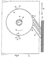
- the second support 3 comprises, on its upper surface, a cylindrical hub 10 integral with three blades 12 arranged tangentially to the hub 10 and around which is placed a toothed wheel 11.
- this toothed wheel 11 has teeth 16 on its outer peripheral surface 17 and an inner peripheral surface 19, preferably roughened, designed to cooperate with said blades 12 to form a non-return device for the toothed wheel 11.
- the transmission means to the toothed wheel 11 of the relative movement between the two parts 2 and 3 of the support S comprise at least two driving beams 20, only one of which is shown for clarity and to illustrate more simply the principle of counting, the actual size of the teeth of the toothed wheel and the driving beam may be more than a thousand times smaller than that of the teeth shown.
- Each of these beams 20 is integral with the first support 2 and has a tooth 21 at its free end 22, this tooth 21 being able to form a gear, ratchet type, with those of said toothed wheel 11.
- each of the teeth 16 of this first toothed wheel 11 comprises a first radial surface 23 and an inclined surface 24 connecting the upper end 25 of said first radial surface. at the base 26 of the radial surface of the next tooth.
- the tooth 21 secured to the driving beam 20 has an inclined surface 27 and a radial surface 28, the latter being in facing relation with said first radial surface 23 of a tooth 16 of the first counting wheel 11.
- the tooth 21 of the driving beam has a drive face which comes into contact with the tooth of the counting wheel to pull the wheel during a displacement in one direction of the driving element and a guide face. allowing the sliding element, and thus the retraction, of the driving element on the tooth of the counting wheel during a displacement in the opposite direction to the preceding one of the driving element.
- the driving beam has sufficient elasticity to allow the retraction of a tooth 16 without deterioration.
- the spacing between the pads varies and the points A and B are found in the extreme positions A 'and B', their coordinates then being x A ' and x B' while the pads return to their original or slightly different position at the end of the solicitation or a certain time later.
- This spacing difference between the studs 5 and 6 causes a variation of positioning between the first and the second support, respectively 2 and 3.
- said positioning variation produces a drive of the toothed wheel 11 by the driving beam 20 in the direction of the arrow.
- the relative displacement of the tooth 21 of the beam 20 relative to the second support 3 is of the order of magnitude of the pitch of the teeth 16 of the toothed wheel 11, namely, one and a half times larger, the toothed wheel 11 will be rotated by the tooth 21 of the driving beam 20, the respective radial faces 23 and 28 of the tooth n of the toothed wheel 11 and the tooth 21 of the driving beam 20 being in contact.
- the pads, and therefore the corresponding supports will return to their initial position but the anti-return device consisting of the blades 12 and second teeth 18 of the toothed wheel 11, prevents the toothed wheel 11 to turn in the opposite direction to that of the arrow while, due to its elasticity, the inclined face 27 of the tooth 21 of the driving beam slides on that of the tooth n + 1 of the toothed wheel 11 with which it is in contact until it reaches the top 25 of this tooth, the radial face 28 of the tooth 21 of the driving beam then being opposite the radial face 23 of the tooth n + 1 of the wheel toothed 11.
- the spacing of the studs 5 and 6, following a bias produces a drive of the toothed wheel 11 by the driving tooth 21 of the driving beam 20 while the approximation of these two parts, to the end of the bias, produces a maintenance of the first toothed wheel 11 by the non-return device 12, 19 and a retraction of the tooth 21 of the driving beam 20 on a tooth 16 of the first toothed wheel 11.
- the detection by the microsensor of a cycle of distance variations results in a rotation of the toothed wheel 11, marks associated with this wheel then making it possible to determine the number of cycles undergone by the structure from an origin, where between two given times.
- the studs can also be replaced by notches or by bores.
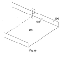
- each of the pads is replaced by at least one bore and preferably two bores positioned so that their diameter d is much smaller than the distance D separating their axis, for example d / D ⁇ 0.2.
- the production of studs, notches or boring as anchoring zone makes it possible to know precisely the distance L separating the anchoring zones and thus to allow the counting of the cycles of variations in distance. between two points A and B of a structure. Knowing the characteristics of the deformation of the structure, and taking into account the pitch P of the teeth of the counting wheel and the number m of driving beams, the distance L between the anchoring points is determined so that during the deformation of the structure, the variation in distance between the anchoring zones 5 and 6 is greater than the P / m ratio and preferably close to or equal to 1.5. P / m.
- the mechanism of subdivision of the pitch via the use of a transmission device to a gear wheel of a relative movement between a first and a second part of a support of a microsensor able to move or to be moved l one with respect to the other under the effect of a constraint, the first movable element being integral with one of said first and second parts and several driving beams, integral with the other of said first and second parts and each comprising a tooth at one of its ends adapted to form a gear with those of the movable member, is presented in the context of a second embodiment of a sensor 30 according to the invention.
- This mechanism is particularly useful for detecting and counting very small relative motions between said parts, for example submicron displacements, which may especially be the case during relative displacements involved in mechanical compression phenomena or thermal expansion.
- it makes it possible to detect and count relative displacements between the first and second parts of the lower support at the pitch P of the toothing of the toothed wheel.
- This principle makes it possible, on the one hand, to increase the sensitivity of the sensor since it makes it possible to access levels of sensitivity greater than the periodicity of the geometric patterns to which the manufacturing technology makes it possible to arrive, and on the other hand the use of less sophisticated techniques for the realization of the component therefore result in a lower manufacturing cost and a better robustness of the sensor.
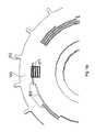
- the figures 6 and 7 more particularly, a counting means comprising transmission means comprising 4 beams allowing a subdivision of the pitch by 5.
- a sensor 31 according to this second embodiment of the invention comprises a first support 32 and a second support 33, the latter having a cylindrical hub 34 integral with three blades 39 arranged tangentially to the hub 34 and around which is placed a gear wheel 35.
- This toothed wheel 35 has teeth 36 on its outer peripheral surface 37 and an inner peripheral surface 38 of cylindrical shape.
- Five driving beams 40 integral with the first support 32 and arranged substantially parallel to each other, each have a tooth 41 at their free end 42, these teeth 41 being arranged between them at a distance multiple of the pitch P of the toothing of the wheel plus a fraction of this pitch, namely a fifth of this pitch so that only one of these teeth constitutes a gear with teeth 36 of said gear wheel 35.
- I 1 and I 2 are natural whole numbers and: I 2 ⁇ 0 I 1 ⁇ 0 if 2 I ⁇ m
- each of the teeth 36 of this first toothed wheel 11 comprises a first radial surface 43 and an inclined surface 42 connecting the upper end 44 of said first radial surface to the base 48 of the radial surface 43 of the next tooth.
- each of the teeth 41 integral with the driving beam 40 has an inclined surface 46 and a radial surface 45, the latter being, for one of the teeth 41, facing each other with respect to said first radial surface 43 of a tooth 36 of the first counting wheel 35.
- the drive beams 40 have sufficient elasticity to allow the retraction of their tooth 41 on a tooth 36 of the first counting wheel 35, and without deterioration.
- the inner peripheral surface 38 of the toothed wheel 35 and the end of said blades 39 are intended to cooperate to form an elastic means of accommodation of the gear 35 on the hub 34, the friction force of the end of the blades 39 on the inner peripheral surface 38 of the wheel 35 being, on the one hand, greater than that which can cause the drive beams when they are directed in a first direction OX, then causing a sliding of the teeth 41 of the beams 40 on the wheel 35 and, on the other hand, lower than that which can be generated by the driving beams when they are in a second direction OX ', opposite to said direction OX, thus causing a sliding of the inner peripheral surface 38 of the wheel 35 on the ends of the blades 39.
- the sliding of the wheel on the ends of the blades 39 is allowed by a correct dimensioning of the elastic accommodation means of the resistant torque relative to the possible shear of the tooth 41 of the beam 40 or that, 36, of the toothed wheel 35.
- the figure 7 shows a diagram of the operation of the counting means constituted by the beams, the toothed wheel 35, the hub 34 and the means of resilient accommodation of the resisting torque and for which the second portion 33 of the support S1 is assumed, in this example, to move relative to the first portion 32 of the support S1 in the direction OX '.
- the different phases are respectively numbered from 1 to 5 and from A to E.
- phase A the gear 35 has moved relative to the fixed beams 40.
- the beam 3 crosses the tooth represented in dark gear 35, and because of the geometrical configuration of the teeth, prohibits the return of the tooth, the beams 40 being represented on this first diagram just before the passage of the tooth to identify properly the sequences, instead of representing them after the crossing.
- the beams 4 and 5 are flexed by the toothing.
- the beams 1 and 2 will also be bent during the next relative displacement of the wheel.
- phase C the beam 5 has just crossed the teeth of the wheel and prohibits its return to another place than that of phase B. It is the same phase D and E.
- the beam 3 again passes a tooth of the toothed wheel.
- This tooth is the one that follows the one shown in dark on all the diagrams.
- the five biasing cycles were translated at the first wheel level by meshing a tooth, illustrating the principle of subdivision of the pitch, thus the possibility of detecting and recording information with a resolution higher than the intrinsic one of the system.
- Such a device makes it possible to detect and count cycles of distance variations of less than 5 ⁇ m. By increasing the number of beams, variations of distances smaller than 1 ⁇ m can be detected and counted.
- FIGS. 8 to 18 show diagrams of a third embodiment of the invention applied to counting the number of vehicles passing on a structure, such as for example a bridge.
- the figures 8 and 9 present one and the other of the two main faces of the sensor according to this third embodiment of the invention.
- a passive sensor for detecting and counting the number of vehicle passages comprises a support 101, mainly U-shaped, thus having a first part 102 and a second part 103 connected to each other by a third part 104. constituting the base of the U, and counting means 105 arranged on the support and comprising at least one first gear 106 disposed on said first portion 102 of the support 101 and, on the one hand, four driving beams 107 of this first toothed wheel 106 fixed at one end 108, their ends 108, 109, to a section 107 'integral with said second portion 103 and each having, at their other end 109, a tooth 110, shown in the simplified figure 10 having only one driving beam, and adapted to constitute a gear 111 with the teeth 112 of the first gear 106, and secondly, a non-return device 113 of the first gear the toothed wheel 106 and such that the bringing together of the first and second parts 102, 103 of the carrier 101 produces a drive of the tooth
- the first and second parts comprise first and second anchoring zones, respectively 224 and 225, constituted by bores in each of which can be inserted a screw for fixing the microsensor on the structure to be analyzed, for example that the parapet of a bridge.
- the bores 224, 225 have a diameter slightly greater than that of said screws.
- first and second anchoring zones 224, 225 are respectively disposed along a first axis Y1 and a second axis Y2 parallel to each other and separated by a distance L
- the faces 133, 134 and 135 of the respective portions 102, 103 and 104 of the support 101 are flat and arranged in the same plane and intended to be pressed against the structure to be analyzed via said screws.
- the third portion 104 of the support itself has an inverted U-shape with a thick base 136.
- This shape makes it possible to have smaller sections at the branches of the U of this beam than of the base 136 and in the case where a large force was exerted at this level.
- third part a break would occur at one of the branches and therefore in a direction parallel to that of the normal movement of the first and second parts, which avoids any relative displacement between these parts in the normal direction of displacement and d avoid any offset between the toothed wheel 106 and the tooth 110 of the driving beam 107.
- the driving beam 107 and the one, 175, of the non-return device are biased in bending on the toothed wheel 106 by their positioning. Indeed the end of the teeth is not tangential to the base of the teeth of the first gear 106 but tangential to a position located closer to the axis of the wheel, As these beams can not go beyond said base, they are automatically subjected to said preload exerted by the first gear 106.
- each tooth 112 of this first gearwheel 106 has a first radial surface 114 and an inclined surface 115 connecting the upper end 116 of said first radial surface to the base 117 of the radial surface of the next tooth.
- the tooth 110 integral with the driving beam 109 comprises an inclined surface 118 and a radial surface 119, the latter being face to face with said first radial surface 114 of a tooth 112 of the first counting wheel 106.
- This first gear 106 has 512 teeth, ie 2 9 .
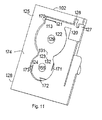
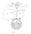
- the figure 11 shows one of the two main faces of the first portion 102 of the support adapted to receive a portion of the counting means 105.
- This surface 174 comprises several successive etchings 120, 121, 122, 123 and 124 having certain common parts.
- the first etching 120 is disposed in the upper portion 125 of the first portion and the side of the first portion 102 of the support. It has the shape of a thick-base U and one of the branches 126 is longer than the other 127.
- the second etching 121 is of elongated rectangular shape and arranged in continuity with the first and toward the side opposite to the third portion 104 of the support 101. However, this etching is not complete because there remains a non-return device 113 disposed longitudinally on less than half the length of the etching and fixed to the first portion 102 of the support 101 by its end located at the transverse side 170 of the etching which is opposite to the first etching 120.
- the third etching 122 is of cylindrical shape and arranged in the continuity of the second and below, that is to say in the direction of the lower part 128 of the first part 102 of the support 101. However, the etching is not not complete because it remains a cylindrical central portion 129.
- This etching 122 is intended to receive the first counting wheel 106 and its diameter is slightly greater than that of the latter.
- the first counting wheel 106 has a central bore and the cylindrical central portion 129 constitutes an axis for this first gear 106.
- the fourth etching 123 is rectangular in shape and has a lower portion 31 of the third etch 122 and an upper portion 132 of the fifth etch 124.
- the fifth etch 124 is of cylindrical shape with a diameter slightly smaller than that of the third etching 122 and arranged tangentially thereto and in the direction of the lower portion 128 of this first portion 123 of the support.
- This etching 124 is intended to receive a second counting gear 130 and is not complete because it remains on the one hand a central part cylindrical intended to serve as axis of rotation 155 to the second counting gear 130 and secondly three beams 171, 172 and 173 respectively arranged to ⁇ / 2 Rd and able to maintain in position and serve as an anti-rotation device. return to the second gear 30.
- the latter has 16 teeth or 2 4 .
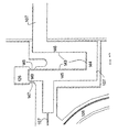
- the figure 12 shows a detail of the intermediate portion 143 of the section 107 'connecting the four drive beams 107 to the second part 103 and which is at the level of the first etching 120 of the first part of the support 101.
- This intermediate portion 143 is U-shaped whose base 144, and the two branches 145, 146 have substantially the same thickness, one, 145, branches being longer than the other and intended to penetrate into the upper part.
- long branch 126 of the first etching of the first support 101 and which, as can be seen in this figure, has two stops 147, 148 each facing one side of the longer portion 149 of the branch 145 of the driving beam.
- These protrusions are to limit the displacement of the drive beam towards the first part of the support, a calibrated value and corresponding substantially to the value of a step and a half of the teeth 112 of the first gear 106.
- These excrescences thus constitute means for limiting the stroke of the teeth 110 of the driving beams 107, or, in other words, stops.
- the thickness of the driving beam beyond this intermediate portion is initially equivalent to that of this portion and then lower to its end comprising the driving tooth 110, this small thickness being adapted to provide sufficient elasticity to allow the drive gear 106 to be driven by the drive tooth 110 in a forward direction and the retraction of this drive tooth 110 to those 112 of the first gear 106 in the return direction.
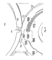
- a third counting gear 150 of smaller diameter than the first gear 106 is fixed on the latter, these two wheels having the same axis of rotation.
- said axis Y1 passes through the axes of rotation of the first, second and third counting wheels as well as the axes of the bores of the first anchoring zones.
- This axis Y1 is perpendicular to the direction X of the deformations of the structure that can be detected by the microsensor on which it is fixed.
- This third counting gear wheel 150 comprises a single tooth 151 in the form of a Gothic arch capable of constituting a gearing with those 152, in the form of a Roman arch, of the second counting wheel 130, these two wheels 130, 150 having the same thickness and being arranged in the same plane.
- This third gear 150 is disposed in the fourth etching 123 of the first portion 102 of the support 101 and has a bore of diameter substantially equal to the axis 155 emerging from the fourth etching.
- the length of the teeth 152 and 151 of the second and third gears 130 and 150 is such that when the tooth 51 of the third gear 150 comes into contact with a tooth 152 of the second gear 130, this contact continues over a substantially equal to the pitch of the teeth 152 of the second gear 130.
- Bar code reader optical reading means are associated with the counting means in order to facilitate reading.
- grooves 166 arc parallel circles in this case four maximum are associated with the teeth 152 of the second gear 130 and allow to number them in a binary manner, the tooth numbered 1 having no associated groove, the tooth number 2 having a groove at a first line 167, the tooth number 3 having a groove at the second line 168, the tooth # 4 having a groove at each of the first two lines 167 and 168 etc. and until the 16 th tooth to which corresponds a groove at each of the four lines 167-170.
- an optical reading is made of the numbering of the teeth on each of the first and second gears 106 and 130 at time to then at moment t1, the reader having the same position at these two moments.
- the image of the first reading at time t0 is that of reference which makes it possible to determine which tooth was engaged at the time of installation of the device.
- the second image is used to identify the tooth engaged at time t1, chosen by the operator.
- the identification of the engaged tooth can be done automatically by importing the two images into an image processing software by generating a mask 177 delimiting the reading zones as shown in FIG. figures 15a and 15b .
- Each reading zone will be either black if there is a throat and equivalent to 1, or white if there is no throat and then equivalent to 0, which makes it possible to calculate the binary number associated with the tooth.
- we read the number 0000 on the figure 15a associated with the second gear, corresponding to 0 in base 10 and 0001 is read on the figure 15b , corresponding to 1x2 0 + 0x2 1 + 0x2 2 + 0x2 3 1 in decimal place.
- This means that the structure has undergone (1 - 0) x 512 events, to which must be added those counted on the first gear and which are determined in the same way.
- This microsensor is positioned on the parapet on either side of a virtual straight line CD.
- the microsensor will not count the passage of the vehicle according to a threshold value corresponding to the mass of the vehicle. It will thus be possible for example to detect, with three identical sensors but arranged at different points of the parapet, the number of vehicles passing from a mass greater than 500 kg for one, the number of vehicles of more than 3500 kg for the second. and all vehicles over 10,000kg for each other.
- ⁇ x (x A ' -x A ) - (x B' -x B ) which is used to actuate the passive counting means, the point A being on the first portion 102 of the support 101 and the point B being on the second portion 103 of the support 101.
- ⁇ x is greater than the pitch of the teeth 112 of the first gear 106 and preferably less than 2 times this step.
- the abutments 147, 148 are able to limit the displacement of the first part of the support 101 relative to the second part by a distance ⁇ x, with respect to their rest position, greater than the pitch of the teeth 112 of the first wheel 106, but less than twice this pitch.
- FIGS. 18a to 18e show, in a simplified way since only one driving beam is shown, the evolution of the positioning of the drive tooth 110 relative to the teeth 112 of the first gear 106 for successive instants t0, t1, t2, t3 and t4, t0 and t4 corresponding to the equilibrium position and t2, the position where the approximation between the first and second parts 102, 103 of the support 101 is maximal.
- the first and second portions 102, 103 of the support 101 are in the rest position.
- the radial face of the drive tooth 110 as well as that of the non-return device 113 are each facing a radial face of a tooth, respectively 200 and 203, of the first toothed wheel 106, the faces facing each other. not being in contact.
- the first and second portions 102, 103 of the support 101 begin to move back to their rest position.
- the inclined face of the drive tooth will come into contact with the inclined face of the tooth 199 and begin to rotate the first gear 106 in the opposite direction to the arrow until the radial face of the tooth.
- anti-return tooth 139 comes into contact with the radial face of the tooth 202. At this time the non-return device will prevent further rotation of the first gear 106 in the opposite direction to that of the arrow.
- the first and second parts 102, 103 of the support have returned to their original position of the figure 18a and only the first toothed wheel 106 does not have its original position since it has rotated by the value of a pitch of its teeth and thus of a tooth, this rotation making it possible to count each passage of the vehicle on the roadway and to the right of the line CD.
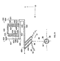
- the figure 19 shows an exemplary embodiment of a sensor intended to be positioned on the lateral surface of the parapet of a bridge and capable of detecting and counting the number of deformation cycles of the parapet of a bridge resulting in a cycle of variation of distance (distance then approximation or vice versa) between two points A and B of the parapet arranged preferably horizontally and at a distance of less than 3 cm from each other, the distance variations being for example between 15 and 100 ⁇ m .
- This sensor 300 comprises a first support 301 made of the same material as the parapet of the bridge, namely aluminum, this feature to cancel the effect of thermal expansion between the parapet and the sensor.
- This support comprises a first portion 302 having first transverse notches 303 of axis Y1 perpendicular to its longitudinal axis X, a second portion 304 in the shape of a U having second transverse notches 305 of axis Y2 perpendicular to the longitudinal axis X, and a third portion 306 having on the one hand an intermediate portion 307 integral with the first portion and separated from the second portion by a U-shaped groove 308 and continuing within the U shape of the second portion and on the other hand two U-shaped portions 309, 310 arranged transversely along an axis Y3 perpendicular to the longitudinal axis X of the support 301.
- the function of the two U-shaped portions 309, 310 is to maintain the positioning of the first part by relative to the second part before and during the fixing of the sensor on the reception structure namely the parapet of the bridge.
- the first and second notches are intended to receive glue in order to fix the support 301 on the host structure and thus to obtain fixed areas of small width and located at predetermined locations and allowing optimal operation of the sensor.
- Two cylindrical studs 311, 312 are each fixed in a bore made in the second part of the support. Their function is to guide the positioning of a plate 314, made here in silicon and of square shape.
- This plate has an opening 315 L-shaped, one of its ends 316 opens towards the middle of a first side 317 of the square while its other end 318 is located at the middle of a second side 319 of the square adjacent said first side 317 but without opening on the second side so that a thin material width 320 remains at this level.
- this plate is constituted by a first and a second part, respectively 321 and 322, second portion whose width is substantially equal to that of the intermediate portion 307 of the third portion 306 and intended to be fixed on the latter.
- Each of the first and second parts 321, 322 of the plate has an opening 324 of oblong shape disposed with a transverse axis coinciding with the axis Y2 for fixing the second portion 304 of the support 301 along said axis Y2 as shown in FIG. figure 21 .
- These openings are intended to receive glue in order to fix the plate 314 on the support 301, and more precisely to fix the first portion 321 of the plate 314 on the second portion 304 of the support 301 and the second portion 322 of the plate 314 on said intermediate portion 307 which is integral with the first portion 302 of the support 301, and thus obtain fastening areas of small width and located at predetermined locations.
- the L-shaped opening 315 is above said U groove 308 separating said intermediate portion 307 from the second portion 304 of the support 301.
- the portion 320 is destroyed once the piece 314 stuck on the support 301. It serves just to maintain position before and during the bonding phase.
- a driving beam 329 which has a tooth 330 at its first end, at its second end which is integral with the second portion 322 of the plate 314 at said first side 317 of the square. It extends parallel to the side of this second portion 322 located on the side of said first side 317.
- a counting gear wheel 328 is mounted on a bearing 331 of tubular shape and having a shoulder 332 on which the toothed wheel 328 rests, this bearing 331 being able to rotate about an axis of rotation 333 integral with the second part of the support 301 and so that the toothed wheel 328 forms, with the tooth 330 of the beam 329, a gear while the use of a complementary friction pad 335 provides a set forming a pawl, as explained for example in the context of the figure 4 .
- the bearing 331 has protrusions 334 on its base capable of limiting the friction with the support 304 during its rotations.
- the tooth 330 of the driving beam 329 bears against the toothed wheel 328 and thus is prestressed. Since such a sensor is intended to detect and count the deformations of the structure in the X direction, the prestressing of the driving beam 329 makes it possible to compensate for deformations of the structure in the direction Y2.
- the compensation of the temperature can be carried out by adapting the length of the first part of the support and / or of said intermediate part so that the product of the distance separating the two bonding axes Y1, Y2 of the sensor on the receiving structure by the coefficient of expansion of the material constituting the receiving structure is equal to the product of the distance separating said Y1 axis of bonding to the tooth of the driving beam by the coefficient of thermal expansion of the sensor support.
- a first sensor positioned the lowest can count the passage of all vehicles whose mass is greater than 500kg
- a second sensor placed in an intermediate position can count the passage of all vehicles over 3 tons
- a third sensor located even more high will only count the passage of vehicles over 10 tonnes.
- the figure 22 shows a second embodiment of the plate 314 wherein the first and second portions 321, 322 are secured by a U-shaped resilient intermediate member 340, said thin material width 320 has also been removed.
- This intermediate element 340 makes it possible on the one hand to maintain the positioning of said first and second parts 321, 322 before and during their bonding on the respective parts 304 and 307 while its elasticity allows a relative displacement of said first and second parts 321, 322 when the structure on which is fixed the sensor is subjected to a bias producing a variation in distance between the points A and B of the sensor, this displacement producing a rotation of the counting wheel via the driving beam 329.
- the microsensor is totally passive, and it is the event itself (action of an object capable of bending a structure) that provides the energy necessary to activate the detection and counting functions.
- the microsensor is put into operation for a time that is not limited by the life of the energy source.
- the life expectancy of the sensor is in all cases much greater than that of all weapon systems, including passive systems stored for very short periods of time. long periods.
- a microsensor according to the invention is totally insensitive to electromagnetic fields.
- the proposed solution is very simple to implement and its operation very reliable. It is independent of a source of energy, discrete, and a low unit cost.
- the counting means comprises a plurality of beams capable of successively driving the toothed wheel in one and the same direction
- these beams may be arranged on the same side of the toothed wheel as on FIG. figure 6 or, for example, partly on one side and partly on the other without the operation of the device being changed.
- the teeth of said beams can be placed at the same distance from each other or at different distances while respecting the formula of the spacing E given in the description.
- the tooth of the non-return beam as shown on the figure 10 can be replaced by a friction pad adapted to apply a friction force on the counting gear.
- His role is twofold. In both cases, it is the frictional force of the pad on the wheel that allows it to play its role. This friction force is determined by the prestressing of the slider beam. It limits on the one hand an excessive rotation due to inertial effects of the counting wheel in the normal direction of rotation. It also prevents a rotation of the counting wheel in the direction opposite to the normal direction during the return of the driving tooth, provided that the friction force of the pad is greater than that of the driving beam. wheel.
- the subdivision mechanism can in particular be applied to the improvement of the performance of an actuator or the capture of a source of energy of any origin, for example for the recovery of lost energy ...
- the subdivision drive mechanism can thus be extended to the actuators involving mechanical oscillations of low amplitude which is the case of MEMS actuators in particular and electrostatic actuators in particular.
- any mechanical oscillation of very small amplitude whatever its origin, for example mechanical, vibratory or thermal can be transferred in step mode to a toothed wheel whose pitch is greater than the amplitude of the oscillation.
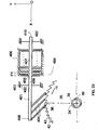
- figures 23 and 24 show devices using an electrostatic actuator upstream of the subdivision drive mechanism.
- the subdivision mechanism therefore makes it possible, in the particular case of MEMS electrostatic actuators, to use parallel-plate electric field interaction actuators in step-by-step mode and without any useful stroke limitation.
- the subdivision mechanism can be applied to the trivialization of the technologies used for the manufacture of the cogwheel acting as interface between the actuator and the host product ...
- a conventional air gap can be maintained, typically 10 microns or a few tens of microns, but a gear wheel having a pitch greater than 1 micron is used. amplitude sensed.
- the subdivision mechanism can therefore be used to expand the pitch of the gear wheel by maintaining the amplitude of the actuator at a standard value. For example, with a subdivision factor of 5 and an amplitude of 30 microns, a wheel pitch of 150 microns is obtained, easily achievable by means of conventional low-cost technologies (plastic injection, cutting, etc.).
- the ability to increase the pitch of the toothed wheel or rack can therefore significantly reduce the production cost of the toothed wheel that acts as an interface between the MEMS actuator and the host product (example: the quartz watch ).
- the figure 25 shows another application of a device according to the invention in order to recover energy generated by oscillations of very low amplitude of a material 450.
- This device comprises a first longitudinal support 451, fixed at one end, 452, of its ends 452, 455, to the material 450 and held in a direction OY by elastic suspensions 453 disposed at its middle portion 454 and its ends. 452 and secured to a third support 454.
- Three beams 404 are fixed at the second end 455 of the first longitudinal support 451 and directed towards the teeth 456 of a cylinder spring 457 whose central end 458 is fixed on an axis 459 itself secured to a second support 461.
- a non-return device 460 tooth such as that of the figure 4 , is associated with the barrel spring teeth.
- any movement of the material, 450 along the direction OX produces a displacement between the first support 451 and thus beams in this same direction and then produces a relative movement between the first and the second support.
- One of these beams then drives the tooth against which it rests in the indicated direction while when the material returns to its original position, the first support and, consequently, the associated beams return to their position of origin while non-return device keeps the mainspring in its new position.
- the energy thus accumulated by the mainspring spring following multiple oscillations of the material 450 can then be used for example to drive a second material.
Landscapes
- Physics & Mathematics (AREA)
- General Physics & Mathematics (AREA)
- Engineering & Computer Science (AREA)
- Theoretical Computer Science (AREA)
- Length Measuring Devices With Unspecified Measuring Means (AREA)
- Transmission And Conversion Of Sensor Element Output (AREA)
- Gears, Cams (AREA)
- Micromachines (AREA)
Applications Claiming Priority (1)
| Application Number | Priority Date | Filing Date | Title |
|---|---|---|---|
| FR0703754A FR2916843A1 (fr) | 2007-05-29 | 2007-05-29 | Microcapteur apte a detecter une variation de distance ou un cycle de variations de distance entre deux points ou zones d'une structure lors d'une sollicitation. |
Publications (4)
| Publication Number | Publication Date |
|---|---|
| EP1998144A2 true EP1998144A2 (de) | 2008-12-03 |
| EP1998144A3 EP1998144A3 (de) | 2013-10-30 |
| EP1998144B1 EP1998144B1 (de) | 2019-05-01 |
| EP1998144B8 EP1998144B8 (de) | 2019-06-26 |
Family
ID=38935777
Family Applications (2)
| Application Number | Title | Priority Date | Filing Date |
|---|---|---|---|
| EP08290493.9A Active EP1998145B8 (de) | 2007-05-29 | 2008-05-28 | Mikrosensor zum Erfassen einer Entfernungsänderung oder eines Zyklus von Entfernungsänderungen zwischen zwei Punkten oder Zonen einer Struktur bei Belastung |
| EP08290492.1A Active EP1998144B8 (de) | 2007-05-29 | 2008-05-28 | Vorrichtung zur Übertragung einer relativen Bewegung zwischen einem zweiten und einem dritten Element eines Systems an ein erstes bewegliches Element mit Zähnen |
Family Applications Before (1)
| Application Number | Title | Priority Date | Filing Date |
|---|---|---|---|
| EP08290493.9A Active EP1998145B8 (de) | 2007-05-29 | 2008-05-28 | Mikrosensor zum Erfassen einer Entfernungsänderung oder eines Zyklus von Entfernungsänderungen zwischen zwei Punkten oder Zonen einer Struktur bei Belastung |
Country Status (4)
| Country | Link |
|---|---|
| EP (2) | EP1998145B8 (de) |
| DK (2) | DK1998145T3 (de) |
| ES (2) | ES2737424T3 (de) |
| FR (3) | FR2916843A1 (de) |
Cited By (3)
| Publication number | Priority date | Publication date | Assignee | Title |
|---|---|---|---|---|
| WO2010095008A1 (en) * | 2009-02-18 | 2010-08-26 | Aktiebolaget Skf | Contactless sensor and detecting assembly comprising such a contactless sensor |
| WO2015001204A1 (fr) * | 2013-07-02 | 2015-01-08 | ÉTAT FRANÇAIS représenté par LE DÉLÉGUÉ GÉNÉRAL POUR L'ARMEMENT | Microcapteur passif et réversible amplifié de déformations |
| FR3025599A1 (fr) * | 2014-09-10 | 2016-03-11 | France Etat | Procede de comptage d'evenements survenus pendant une duree t et compteurs mecaniques d'evenements associes |
Families Citing this family (3)
| Publication number | Priority date | Publication date | Assignee | Title |
|---|---|---|---|---|
| FR2974410B1 (fr) | 2011-04-22 | 2015-05-29 | France Etat | Capteur passif et reversible de deformations |
| FR3048500B1 (fr) * | 2016-03-02 | 2018-03-02 | Etat Francais Represente Par Le Delegue General Pour L'armement | Capteur de deformation permettant une discrimination de mesure en fonction de la direction de la deformation |
| EP3336485B1 (de) | 2016-12-15 | 2020-09-23 | Safran Landing Systems UK Limited | Flugzeuganordnung mit ablenkungssensor |
Citations (2)
| Publication number | Priority date | Publication date | Assignee | Title |
|---|---|---|---|---|
| FR703754A (fr) | 1930-10-16 | 1931-05-06 | Manuf De Machines Modernes | Perfectionnements au montage des cylindres porte-cliché dans les machines à imprimer |
| FR2893139A1 (fr) | 2005-09-13 | 2007-05-11 | France Etat | Micro capteur apte a detecter et a compter des chocs ou des accelerations/decelerations. |
Family Cites Families (5)
| Publication number | Priority date | Publication date | Assignee | Title |
|---|---|---|---|---|
| CH497725A (de) * | 1962-01-31 | 1964-12-31 | Straumann Inst Ag | Antrieb für ein mit tonfrequenten, translatorischen Oszillationen angetriebenes Zeitmessgerät |
| US5452335A (en) * | 1992-12-31 | 1995-09-19 | Symbiosis Corporation | Temperature cycle counter |
| US6617963B1 (en) * | 1999-02-26 | 2003-09-09 | Sri International | Event-recording devices with identification codes |
| FR2875324A1 (fr) | 2004-09-13 | 2006-03-17 | Parifex | Systeme de detection de passage et de comptage de vehicules a moteur |
| FR2890748A1 (fr) * | 2005-09-13 | 2007-03-16 | France Etat Armement | Micro capteur apte a detecter et a compter des chocs ou des accelerations/decelerations. |
-
2007
- 2007-05-29 FR FR0703754A patent/FR2916843A1/fr active Pending
-
2008
- 2008-05-28 DK DK08290493.9T patent/DK1998145T3/da active
- 2008-05-28 ES ES08290492T patent/ES2737424T3/es active Active
- 2008-05-28 EP EP08290493.9A patent/EP1998145B8/de active Active
- 2008-05-28 ES ES08290493T patent/ES2729924T3/es active Active
- 2008-05-28 DK DK08290492.1T patent/DK1998144T3/da active
- 2008-05-28 EP EP08290492.1A patent/EP1998144B8/de active Active
- 2008-05-29 FR FR0802917A patent/FR2916882A1/fr active Pending
- 2008-05-29 FR FR0802916A patent/FR2916844A1/fr active Pending
Patent Citations (2)
| Publication number | Priority date | Publication date | Assignee | Title |
|---|---|---|---|---|
| FR703754A (fr) | 1930-10-16 | 1931-05-06 | Manuf De Machines Modernes | Perfectionnements au montage des cylindres porte-cliché dans les machines à imprimer |
| FR2893139A1 (fr) | 2005-09-13 | 2007-05-11 | France Etat | Micro capteur apte a detecter et a compter des chocs ou des accelerations/decelerations. |
Cited By (8)
| Publication number | Priority date | Publication date | Assignee | Title |
|---|---|---|---|---|
| WO2010095008A1 (en) * | 2009-02-18 | 2010-08-26 | Aktiebolaget Skf | Contactless sensor and detecting assembly comprising such a contactless sensor |
| WO2015001204A1 (fr) * | 2013-07-02 | 2015-01-08 | ÉTAT FRANÇAIS représenté par LE DÉLÉGUÉ GÉNÉRAL POUR L'ARMEMENT | Microcapteur passif et réversible amplifié de déformations |
| FR3008179A1 (fr) * | 2013-07-02 | 2015-01-09 | France Etat | Microcapteur passif et reversible de deformations |
| US9939246B2 (en) | 2013-07-02 | 2018-04-10 | Etat Francais Represente Par Le Delegue General Pour L'armement | Amplified passive and reversible micro-sensor of deformations |
| FR3025599A1 (fr) * | 2014-09-10 | 2016-03-11 | France Etat | Procede de comptage d'evenements survenus pendant une duree t et compteurs mecaniques d'evenements associes |
| WO2016038256A1 (fr) * | 2014-09-10 | 2016-03-17 | Etat Francais Represente Par Le Delegue General Pour L'armement | Procédé de comptage d'événements survenus pendant une durée t et compteurs mécaniques d'événements associés |
| JP2017527910A (ja) * | 2014-09-10 | 2017-09-21 | エタ・フランセ・ルプレザンテ・パール・ル・デレゲ・ジェネラル・プール・ラルムマンETAT FRANCAIS represente par LE DELEGUE GENERAL POUR L’ARMEMENT | 経過時間t中に発生するイベントを計数する方法、および、関連する機械式イベントカウンタ |
| US10401192B2 (en) | 2014-09-10 | 2019-09-03 | Etat Francais Represente Par Le Delegue General Pour L'armement | Method for counting events occurring during a duration T and associated mechanical event counters |
Also Published As
| Publication number | Publication date |
|---|---|
| EP1998145B1 (de) | 2019-03-27 |
| EP1998145B8 (de) | 2019-06-26 |
| ES2737424T3 (es) | 2020-01-14 |
| DK1998145T3 (da) | 2019-06-24 |
| FR2916844A1 (fr) | 2008-12-05 |
| EP1998145A3 (de) | 2013-06-19 |
| FR2916843A1 (fr) | 2008-12-05 |
| FR2916882A1 (fr) | 2008-12-05 |
| EP1998144A3 (de) | 2013-10-30 |
| EP1998144B8 (de) | 2019-06-26 |
| DK1998144T3 (da) | 2019-07-29 |
| ES2729924T3 (es) | 2019-11-07 |
| EP1998144B1 (de) | 2019-05-01 |
| EP1998145A2 (de) | 2008-12-03 |
Similar Documents
| Publication | Publication Date | Title |
|---|---|---|
| EP1998144B1 (de) | Vorrichtung zur Übertragung einer relativen Bewegung zwischen einem zweiten und einem dritten Element eines Systems an ein erstes bewegliches Element mit Zähnen | |
| WO2014072317A2 (fr) | Procédé de réalisation d'un élément flexible multistable | |
| EP2677372B1 (de) | Rad mit Spielnachstellung | |
| WO2004081695A2 (fr) | Dispositif mems comprenant un actionneur apte a generer un mouvement d’entrainement a hysteresis. | |
| EP2801868B1 (de) | Hemmungsrad | |
| EP3423780B1 (de) | Dehnungssensor mit messungsunterscheidung nach verformungsrichtung | |
| EP0580049B1 (de) | Piezo-elektrischer Motor | |
| EP3017278B1 (de) | Verstärkter passiver und umkehrbarer verformungsmikrosensor | |
| EP2705330B1 (de) | Passiver umkehrbarer verformungssensor | |
| FR2985721A1 (fr) | Indexation passive d'un element mobile presentant des dents | |
| CH704915B1 (fr) | Dispositif d'affichage sautant amélioré. | |
| CH713787A2 (fr) | Dispositif horloger à organe de positionnement. | |
| CH705300A2 (fr) | Roue d'échappement. | |
| WO2019111195A1 (fr) | Pièce de micromécanique horlogère | |
| EP4332686A1 (de) | Spiralfeder für eine spiralunruh-einheit einer uhrwerke | |
| FR2893139A1 (fr) | Micro capteur apte a detecter et a compter des chocs ou des accelerations/decelerations. | |
| EP2735923B1 (de) | Zeigerantriebsmechanismus einer elektromechanischen Uhr, der mit einer Verriegelung ausgestattet ist | |
| EP3707564B1 (de) | Zusammenstellung einer uhrenkomponente und einer vorrichtung zur steuerung in längsrichtung einer beweglichen komponente | |
| EP3579059B1 (de) | Anzeigesystem, das ein anzeigemodul mit beweglichen organgen um verformbare verbindungen herum und eine reversible blockiervorrichtung dieser beweglichen organe in mindestens einer position umfasst | |
| CH710817B1 (fr) | Mouvement horloger à régulateur résonant à interaction magnétique. | |
| CH719120B1 (fr) | Mécanisme horloger comprenant un sautoir et un composant denté monté pivotant. | |
| FR3152318A1 (fr) | Dispositif micromécanique de comptage de chocs | |
| CH714767B1 (fr) | Dispositif de collecte d'énergie mécanique notamment pour pièce d'horlogerie, mouvement horloger et pièce d'horlogerie comprenant un tel dispositif. | |
| FR2890748A1 (fr) | Micro capteur apte a detecter et a compter des chocs ou des accelerations/decelerations. |
Legal Events
| Date | Code | Title | Description |
|---|---|---|---|
| PUAI | Public reference made under article 153(3) epc to a published international application that has entered the european phase |
Free format text: ORIGINAL CODE: 0009012 |
|
| AK | Designated contracting states |
Kind code of ref document: A2 Designated state(s): AT BE BG CH CY CZ DE DK EE ES FI FR GB GR HR HU IE IS IT LI LT LU LV MC MT NL NO PL PT RO SE SI SK TR |
|
| AX | Request for extension of the european patent |
Extension state: AL BA MK RS |
|
| RIN1 | Information on inventor provided before grant (corrected) |
Inventor name: LOUVIGNE. PIERRE-FRANCOIS Inventor name: VESCOVO, PAUL Inventor name: HELIN, PHILIPPE Inventor name: MINOTTI, PATRICE Inventor name: JOSEPH, ERIC Inventor name: WALTER, VINCENT |
|
| RIC1 | Information provided on ipc code assigned before grant |
Ipc: G06M 1/04 20060101ALI20130521BHEP Ipc: G01D 5/04 20060101ALI20130521BHEP Ipc: G01D 1/04 20060101AFI20130521BHEP |
|
| PUAL | Search report despatched |
Free format text: ORIGINAL CODE: 0009013 |
|
| AK | Designated contracting states |
Kind code of ref document: A3 Designated state(s): AT BE BG CH CY CZ DE DK EE ES FI FR GB GR HR HU IE IS IT LI LT LU LV MC MT NL NO PL PT RO SE SI SK TR |
|
| AX | Request for extension of the european patent |
Extension state: AL BA MK RS |
|
| RIC1 | Information provided on ipc code assigned before grant |
Ipc: G06M 1/04 20060101ALI20130925BHEP Ipc: G01D 1/04 20060101AFI20130925BHEP Ipc: G01D 5/04 20060101ALI20130925BHEP |
|
| 17P | Request for examination filed |
Effective date: 20140304 |
|
| 17Q | First examination report despatched |
Effective date: 20140506 |
|
| AKX | Designation fees paid |
Designated state(s): AT BE BG CH CY CZ DE DK EE ES FI FR GB GR HR HU IE IS IT LI LT LU LV MC MT NL NO PL PT RO SE SI SK TR |
|
| 17Q | First examination report despatched |
Effective date: 20141105 |
|
| RAP1 | Party data changed (applicant data changed or rights of an application transferred) |
Owner name: ETAT FRANCAIS REPRESENTE PAR LE DELEGUE GENERAL PO |
|
| STAA | Information on the status of an ep patent application or granted ep patent |
Free format text: STATUS: EXAMINATION IS IN PROGRESS |
|
| GRAP | Despatch of communication of intention to grant a patent |
Free format text: ORIGINAL CODE: EPIDOSNIGR1 |
|
| STAA | Information on the status of an ep patent application or granted ep patent |
Free format text: STATUS: GRANT OF PATENT IS INTENDED |
|
| INTG | Intention to grant announced |
Effective date: 20181011 |
|
| GRAS | Grant fee paid |
Free format text: ORIGINAL CODE: EPIDOSNIGR3 |
|
| GRAJ | Information related to disapproval of communication of intention to grant by the applicant or resumption of examination proceedings by the epo deleted |
Free format text: ORIGINAL CODE: EPIDOSDIGR1 |
|
| GRAL | Information related to payment of fee for publishing/printing deleted |
Free format text: ORIGINAL CODE: EPIDOSDIGR3 |
|
| STAA | Information on the status of an ep patent application or granted ep patent |
Free format text: STATUS: EXAMINATION IS IN PROGRESS |
|
| GRAR | Information related to intention to grant a patent recorded |
Free format text: ORIGINAL CODE: EPIDOSNIGR71 |
|
| STAA | Information on the status of an ep patent application or granted ep patent |
Free format text: STATUS: GRANT OF PATENT IS INTENDED |
|
| GRAJ | Information related to disapproval of communication of intention to grant by the applicant or resumption of examination proceedings by the epo deleted |
Free format text: ORIGINAL CODE: EPIDOSDIGR1 |
|
| STAA | Information on the status of an ep patent application or granted ep patent |
Free format text: STATUS: EXAMINATION IS IN PROGRESS |
|
| GRAR | Information related to intention to grant a patent recorded |
Free format text: ORIGINAL CODE: EPIDOSNIGR71 |
|
| STAA | Information on the status of an ep patent application or granted ep patent |
Free format text: STATUS: GRANT OF PATENT IS INTENDED |
|
| GRAA | (expected) grant |
Free format text: ORIGINAL CODE: 0009210 |
|
| STAA | Information on the status of an ep patent application or granted ep patent |
Free format text: STATUS: THE PATENT HAS BEEN GRANTED |
|
| INTC | Intention to grant announced (deleted) | ||
| INTG | Intention to grant announced |
Effective date: 20190320 |
|
| AK | Designated contracting states |
Kind code of ref document: B1 Designated state(s): AT BE BG CH CY CZ DE DK EE ES FI FR GB GR HR HU IE IS IT LI LT LU LV MC MT NL NO PL PT RO SE SI SK TR |
|
| INTG | Intention to grant announced |
Effective date: 20190325 |
|
| REG | Reference to a national code |
Ref country code: GB Ref legal event code: FG4D Free format text: NOT ENGLISH |
|
| GRAT | Correction requested after decision to grant or after decision to maintain patent in amended form |
Free format text: ORIGINAL CODE: EPIDOSNCDEC |
|
| REG | Reference to a national code |
Ref country code: CH Ref legal event code: EP Ref country code: AT Ref legal event code: REF Ref document number: 1127548 Country of ref document: AT Kind code of ref document: T Effective date: 20190515 |
|
| REG | Reference to a national code |
Ref country code: DE Ref legal event code: R096 Ref document number: 602008059897 Country of ref document: DE |
|
| REG | Reference to a national code |
Ref country code: IE Ref legal event code: FG4D Free format text: LANGUAGE OF EP DOCUMENT: FRENCH |
|
| REG | Reference to a national code |
Ref country code: CH Ref legal event code: PK Free format text: RECTIFICATION B8 |
|
| RAP2 | Party data changed (patent owner data changed or rights of a patent transferred) |
Owner name: ETAT FRANCAIS REPRESENTE PAR LE DELEGUE GENERAL PO Owner name: SILMACH |
|
| REG | Reference to a national code |
Ref country code: DE Ref legal event code: R082 Ref document number: 602008059897 Country of ref document: DE Representative=s name: CABINET CHAILLOT, FR |
|
| REG | Reference to a national code |
Ref country code: NL Ref legal event code: FP |
|
| REG | Reference to a national code |
Ref country code: DK Ref legal event code: T3 Effective date: 20190724 |
|
| REG | Reference to a national code |
Ref country code: SE Ref legal event code: TRGR |
|
| REG | Reference to a national code |
Ref country code: LT Ref legal event code: MG4D |
|
| REG | Reference to a national code |
Ref country code: NO Ref legal event code: T2 Effective date: 20190501 |
|
| PG25 | Lapsed in a contracting state [announced via postgrant information from national office to epo] |
Ref country code: PT Free format text: LAPSE BECAUSE OF FAILURE TO SUBMIT A TRANSLATION OF THE DESCRIPTION OR TO PAY THE FEE WITHIN THE PRESCRIBED TIME-LIMIT Effective date: 20190901 Ref country code: HR Free format text: LAPSE BECAUSE OF FAILURE TO SUBMIT A TRANSLATION OF THE DESCRIPTION OR TO PAY THE FEE WITHIN THE PRESCRIBED TIME-LIMIT Effective date: 20190501 Ref country code: LT Free format text: LAPSE BECAUSE OF FAILURE TO SUBMIT A TRANSLATION OF THE DESCRIPTION OR TO PAY THE FEE WITHIN THE PRESCRIBED TIME-LIMIT Effective date: 20190501 |
|
| PG25 | Lapsed in a contracting state [announced via postgrant information from national office to epo] |
Ref country code: BG Free format text: LAPSE BECAUSE OF FAILURE TO SUBMIT A TRANSLATION OF THE DESCRIPTION OR TO PAY THE FEE WITHIN THE PRESCRIBED TIME-LIMIT Effective date: 20190801 Ref country code: LV Free format text: LAPSE BECAUSE OF FAILURE TO SUBMIT A TRANSLATION OF THE DESCRIPTION OR TO PAY THE FEE WITHIN THE PRESCRIBED TIME-LIMIT Effective date: 20190501 |
|
| PG25 | Lapsed in a contracting state [announced via postgrant information from national office to epo] |
Ref country code: IS Free format text: LAPSE BECAUSE OF FAILURE TO SUBMIT A TRANSLATION OF THE DESCRIPTION OR TO PAY THE FEE WITHIN THE PRESCRIBED TIME-LIMIT Effective date: 20190901 |
|
| REG | Reference to a national code |
Ref country code: ES Ref legal event code: FG2A Ref document number: 2737424 Country of ref document: ES Kind code of ref document: T3 Effective date: 20200114 |
|
| REG | Reference to a national code |
Ref country code: GR Ref legal event code: EP Ref document number: 20190402323 Country of ref document: GR Effective date: 20191128 |
|
| PG25 | Lapsed in a contracting state [announced via postgrant information from national office to epo] |
Ref country code: MC Free format text: LAPSE BECAUSE OF FAILURE TO SUBMIT A TRANSLATION OF THE DESCRIPTION OR TO PAY THE FEE WITHIN THE PRESCRIBED TIME-LIMIT Effective date: 20190501 Ref country code: EE Free format text: LAPSE BECAUSE OF FAILURE TO SUBMIT A TRANSLATION OF THE DESCRIPTION OR TO PAY THE FEE WITHIN THE PRESCRIBED TIME-LIMIT Effective date: 20190501 Ref country code: RO Free format text: LAPSE BECAUSE OF FAILURE TO SUBMIT A TRANSLATION OF THE DESCRIPTION OR TO PAY THE FEE WITHIN THE PRESCRIBED TIME-LIMIT Effective date: 20190501 Ref country code: CZ Free format text: LAPSE BECAUSE OF FAILURE TO SUBMIT A TRANSLATION OF THE DESCRIPTION OR TO PAY THE FEE WITHIN THE PRESCRIBED TIME-LIMIT Effective date: 20190501 Ref country code: SK Free format text: LAPSE BECAUSE OF FAILURE TO SUBMIT A TRANSLATION OF THE DESCRIPTION OR TO PAY THE FEE WITHIN THE PRESCRIBED TIME-LIMIT Effective date: 20190501 |
|
| REG | Reference to a national code |
Ref country code: DE Ref legal event code: R097 Ref document number: 602008059897 Country of ref document: DE |
|
| PG25 | Lapsed in a contracting state [announced via postgrant information from national office to epo] |
Ref country code: LU Free format text: LAPSE BECAUSE OF NON-PAYMENT OF DUE FEES Effective date: 20190528 |
|
| PLBE | No opposition filed within time limit |
Free format text: ORIGINAL CODE: 0009261 |
|
| STAA | Information on the status of an ep patent application or granted ep patent |
Free format text: STATUS: NO OPPOSITION FILED WITHIN TIME LIMIT |
|
| PG25 | Lapsed in a contracting state [announced via postgrant information from national office to epo] |
Ref country code: TR Free format text: LAPSE BECAUSE OF FAILURE TO SUBMIT A TRANSLATION OF THE DESCRIPTION OR TO PAY THE FEE WITHIN THE PRESCRIBED TIME-LIMIT Effective date: 20190501 |
|
| 26N | No opposition filed |
Effective date: 20200204 |
|
| PG25 | Lapsed in a contracting state [announced via postgrant information from national office to epo] |
Ref country code: IE Free format text: LAPSE BECAUSE OF NON-PAYMENT OF DUE FEES Effective date: 20190528 Ref country code: PL Free format text: LAPSE BECAUSE OF FAILURE TO SUBMIT A TRANSLATION OF THE DESCRIPTION OR TO PAY THE FEE WITHIN THE PRESCRIBED TIME-LIMIT Effective date: 20190501 |
|
| PG25 | Lapsed in a contracting state [announced via postgrant information from national office to epo] |
Ref country code: SI Free format text: LAPSE BECAUSE OF FAILURE TO SUBMIT A TRANSLATION OF THE DESCRIPTION OR TO PAY THE FEE WITHIN THE PRESCRIBED TIME-LIMIT Effective date: 20190501 |
|
| REG | Reference to a national code |
Ref country code: AT Ref legal event code: UEP Ref document number: 1127548 Country of ref document: AT Kind code of ref document: T Effective date: 20190501 |
|
| PG25 | Lapsed in a contracting state [announced via postgrant information from national office to epo] |
Ref country code: CY Free format text: LAPSE BECAUSE OF FAILURE TO SUBMIT A TRANSLATION OF THE DESCRIPTION OR TO PAY THE FEE WITHIN THE PRESCRIBED TIME-LIMIT Effective date: 20190501 |
|
| PG25 | Lapsed in a contracting state [announced via postgrant information from national office to epo] |
Ref country code: HU Free format text: LAPSE BECAUSE OF FAILURE TO SUBMIT A TRANSLATION OF THE DESCRIPTION OR TO PAY THE FEE WITHIN THE PRESCRIBED TIME-LIMIT; INVALID AB INITIO Effective date: 20080528 Ref country code: MT Free format text: LAPSE BECAUSE OF FAILURE TO SUBMIT A TRANSLATION OF THE DESCRIPTION OR TO PAY THE FEE WITHIN THE PRESCRIBED TIME-LIMIT Effective date: 20190501 |
|
| PGFP | Annual fee paid to national office [announced via postgrant information from national office to epo] |
Ref country code: SE Payment date: 20230314 Year of fee payment: 16 |
|
| PGFP | Annual fee paid to national office [announced via postgrant information from national office to epo] |
Ref country code: NO Payment date: 20230512 Year of fee payment: 16 Ref country code: NL Payment date: 20230516 Year of fee payment: 16 Ref country code: DK Payment date: 20230511 Year of fee payment: 16 |
|
| PGFP | Annual fee paid to national office [announced via postgrant information from national office to epo] |
Ref country code: GR Payment date: 20230530 Year of fee payment: 16 Ref country code: FI Payment date: 20230515 Year of fee payment: 16 Ref country code: AT Payment date: 20230525 Year of fee payment: 16 |
|
| PGFP | Annual fee paid to national office [announced via postgrant information from national office to epo] |
Ref country code: BE Payment date: 20230511 Year of fee payment: 16 |
|
| REG | Reference to a national code |
Ref country code: DK Ref legal event code: EBP Effective date: 20240531 Ref country code: SE Ref legal event code: EUG |
|
| REG | Reference to a national code |
Ref country code: NL Ref legal event code: MM Effective date: 20240601 |
|
| PG25 | Lapsed in a contracting state [announced via postgrant information from national office to epo] |
Ref country code: NO Free format text: LAPSE BECAUSE OF NON-PAYMENT OF DUE FEES Effective date: 20240531 |
|
| REG | Reference to a national code |
Ref country code: AT Ref legal event code: MM01 Ref document number: 1127548 Country of ref document: AT Kind code of ref document: T Effective date: 20240528 |
|
| PG25 | Lapsed in a contracting state [announced via postgrant information from national office to epo] |
Ref country code: GR Free format text: LAPSE BECAUSE OF NON-PAYMENT OF DUE FEES Effective date: 20241204 Ref country code: FI Free format text: LAPSE BECAUSE OF NON-PAYMENT OF DUE FEES Effective date: 20240528 |
|
| PG25 | Lapsed in a contracting state [announced via postgrant information from national office to epo] |
Ref country code: AT Free format text: LAPSE BECAUSE OF NON-PAYMENT OF DUE FEES Effective date: 20240528 |
|
| PG25 | Lapsed in a contracting state [announced via postgrant information from national office to epo] |
Ref country code: NO Free format text: LAPSE BECAUSE OF NON-PAYMENT OF DUE FEES Effective date: 20240531 Ref country code: GR Free format text: LAPSE BECAUSE OF NON-PAYMENT OF DUE FEES Effective date: 20241204 Ref country code: FI Free format text: LAPSE BECAUSE OF NON-PAYMENT OF DUE FEES Effective date: 20240528 Ref country code: AT Free format text: LAPSE BECAUSE OF NON-PAYMENT OF DUE FEES Effective date: 20240528 |
|
| PG25 | Lapsed in a contracting state [announced via postgrant information from national office to epo] |
Ref country code: NL Free format text: LAPSE BECAUSE OF NON-PAYMENT OF DUE FEES Effective date: 20240601 |
|
| REG | Reference to a national code |
Ref country code: BE Ref legal event code: MM Effective date: 20240531 |
|
| PG25 | Lapsed in a contracting state [announced via postgrant information from national office to epo] |
Ref country code: DK Free format text: LAPSE BECAUSE OF NON-PAYMENT OF DUE FEES Effective date: 20240531 |
|
| PG25 | Lapsed in a contracting state [announced via postgrant information from national office to epo] |
Ref country code: BE Free format text: LAPSE BECAUSE OF NON-PAYMENT OF DUE FEES Effective date: 20240531 |
|
| PGFP | Annual fee paid to national office [announced via postgrant information from national office to epo] |
Ref country code: DE Payment date: 20250425 Year of fee payment: 18 |
|
| PGFP | Annual fee paid to national office [announced via postgrant information from national office to epo] |
Ref country code: GB Payment date: 20250422 Year of fee payment: 18 Ref country code: ES Payment date: 20250603 Year of fee payment: 18 |
|
| PGFP | Annual fee paid to national office [announced via postgrant information from national office to epo] |
Ref country code: IT Payment date: 20250424 Year of fee payment: 18 |
|
| PGFP | Annual fee paid to national office [announced via postgrant information from national office to epo] |
Ref country code: FR Payment date: 20250429 Year of fee payment: 18 |
|
| PGFP | Annual fee paid to national office [announced via postgrant information from national office to epo] |
Ref country code: CH Payment date: 20250601 Year of fee payment: 18 |
|
| PG25 | Lapsed in a contracting state [announced via postgrant information from national office to epo] |
Ref country code: SE Free format text: LAPSE BECAUSE OF NON-PAYMENT OF DUE FEES Effective date: 20240529 |