EP2802852B1 - Passive indexierung eines beweglichen elements mit zähnen - Google Patents
Passive indexierung eines beweglichen elements mit zähnen Download PDFInfo
- Publication number
- EP2802852B1 EP2802852B1 EP13700171.5A EP13700171A EP2802852B1 EP 2802852 B1 EP2802852 B1 EP 2802852B1 EP 13700171 A EP13700171 A EP 13700171A EP 2802852 B1 EP2802852 B1 EP 2802852B1
- Authority
- EP
- European Patent Office
- Prior art keywords
- indexing
- teeth
- mobile
- actuator
- displacement
- Prior art date
- Legal status (The legal status is an assumption and is not a legal conclusion. Google has not performed a legal analysis and makes no representation as to the accuracy of the status listed.)
- Active
Links
Images


Classifications
-
- H—ELECTRICITY
- H02—GENERATION; CONVERSION OR DISTRIBUTION OF ELECTRIC POWER
- H02N—ELECTRIC MACHINES NOT OTHERWISE PROVIDED FOR
- H02N1/00—Electrostatic generators or motors using a solid moving electrostatic charge carrier
- H02N1/002—Electrostatic motors
- H02N1/006—Electrostatic motors of the gap-closing type
- H02N1/008—Laterally driven motors, e.g. of the comb-drive type
-
- G—PHYSICS
- G06—COMPUTING OR CALCULATING; COUNTING
- G06M—COUNTING MECHANISMS; COUNTING OF OBJECTS NOT OTHERWISE PROVIDED FOR
- G06M1/00—Design features of general application
- G06M1/04—Design features of general application for driving the stage of lowest order
-
- F—MECHANICAL ENGINEERING; LIGHTING; HEATING; WEAPONS; BLASTING
- F16—ENGINEERING ELEMENTS AND UNITS; GENERAL MEASURES FOR PRODUCING AND MAINTAINING EFFECTIVE FUNCTIONING OF MACHINES OR INSTALLATIONS; THERMAL INSULATION IN GENERAL
- F16H—GEARING
- F16H31/00—Other gearings with freewheeling members or other intermittently driving members
- F16H31/007—Step-by-step mechanisms for linear motion
-
- G—PHYSICS
- G04—HOROLOGY
- G04C—ELECTROMECHANICAL CLOCKS OR WATCHES
- G04C3/00—Electromechanical clocks or watches independent of other time-pieces and in which the movement is maintained by electric means
Definitions
- the invention relates to the field of electromechanical microsystems (MEMS), and more particularly, the locking of MEMS micro-rotor micromotors (mobile element) dedicated to watch applications and scientific instrumentation as well as the locking of MEMS microsensors dedicated to the detection and the passive mechanical storage of structural deformations by means of the engagement of a toothed rotor (counter) (moving element).
- MEMS electromechanical microsystems
- MEMS microtechnologies make it possible to structure mechanical patterns of very small dimensions compared to conventional manufacturing technologies. They make it possible, in particular, to structure rotors and / or microdentated counters which respectively find natural applications in the field of MEMS stepper micromotors with high angular resolution, as well as in the field of MEMS sensors dedicated to the health control of structures.
- MEMS micro-motors with high angular (or linear) resolution have applications in the quartz watch as well as in scientific instrumentation for applications requiring high positioning accuracy.
- This technology takes advantage of the microstructuring potential of the material (i.e. micrometric teeth).
- micromotors also have the advantage of developing motor forces much higher than the devices of the state of the art using the LAVET motor as a drive member.
- the characteristics in charge of the MEMS micromotors make it possible to ensure the direct drive of the mechanical load (needles %) without requiring the recourse to wheels to boost the engine torque by speed reduction.
- the passive MEMS microsensors dedicated to the health control of the structures also implement a passive counter of parasitic mechanical or thermal events (shocks, deformation, expansion, etc.) taking the form of a microdentated rotor.
- the principle of operation consists in implanting a passive sensor (without energy supply) on the surface of a structure undergoing mechanical or thermal stresses, then in accounting, by means of the engagement of a toothing, the structural deformations undergone. by the monitored structure.
- the monitored structure transmits to the sensor a deformation which is read and memorized mechanically by the meshing of a tooth of the microdentated counter.
- the operating principle remains valid regardless of the type of deformation undergone by the structure (traction, compression, bending ).
- the document EP 2 177 960 A1 proposes the use of a locking system of the movable element comprising two indexing fingers which engage the teeth of the movable element so that at least one of the two keeps the movable element at all times.
- the present invention relates to the implementation of mechanisms ensuring the locking of a MEMS micromotor rotor step by step and / or the locking of a counter (ie sensor) likely to undergo parasitic movements conducive to deindexation accidental microdense wheel.
- the driving element is engaged with at least one tooth of the movable element to push or pull the movable element.
- the drive element In the return phase without drive, the drive element is shifted relative to the movable member to be engaged with at least one other tooth of the movable member.
- the device also includes a first indexing element.
- the first indexing element comprises a first indexing finger intended to be intermittently positioned in a space between two teeth of the movable element to prevent uncontrolled movement by the drive element in the direction of movement of the movable element and in the opposite direction.
- the first indexer element is connected to the actuator element so that the actuator element simultaneously moves the drive element and the first indexing finger.
- the first indexing finger can be moved by the actuator element out of the space between the two teeth of the movable element while during the return phase, the first finger of the indexing is positioned by the actuator element in another space between two other teeth of the movable element
- the actuator element may comprise a fixed part and a movable part relative to the fixed part, the driving element and the indexing element being connected to the movable part.
- the first beam and the second beam are interconnected by their respective free ends so that a displacement of the first beam driven by the actuator element causes a bending of the second beam which has the effect of moving the first finger of the first beam. indexing with respect to the movable element.
- the drive element As soon as the drive element is actuated, it causes the simultaneous retraction of the indexing finger responsible for passively locking the rotor in the event of an unexpected shock to the engine.
- the actuator element may comprise a plate extending in a longitudinal direction.
- the plate comprises two blades interconnected by at least two flexible webs and fixed on a support so that deformation in compression or traction of the support generates a movement of a blade relative to each other in a direction of displacement parallel to the longitudinal direction of the plate.
- Each of the blades may include a proximal end and a distal end, and includes at its proximal end a fixation member for attachment to the support.
- a flexible web connects the distal end of one blade to the proximal end of the other blade.
- the device may further include an actuation base attached to one of the blades, the movable member being rotatably attached to the other blade of the plate.
- the actuation base then comprises a base the actuating element and the indexing element.
- the actuating element may comprise a beam which extends parallel to the direction of movement of the blades and has at its free end a drive tooth.
- the indexing element then comprises a first beam extending parallel to the direction of movement of the blades and having at its free end an indexing finger and a second beam extending parallel to the direction of movement of the blades from the free end of the first beam and in the opposite direction, and carrying at its free end a contact surface
- the second blade then comprises an abutment intended to be contacted by the contact surface when moving the blades one by relative to each other to move the first indexing finger away from the moving element
- This device thus makes it possible to passively lock the counter of a MEMS microsensor used in the monitoring of the deformations undergone by a structure.
- a device with a single indexing element is hereinafter described with reference to Figures 1 to 10 .
- the device comprises a movable element 1 comprising teeth 11 and intended to be set in motion, and a driving element 2 intended to engage with the teeth 11 of the movable element 1 to put in motion the mobile element 1 in a direction of movement.
- the device also comprises an actuator element 3 capable of generating reciprocating movement to move the driving element 2.
- the device also comprises an indexing element 4 having an indexing finger 41 intended to be positioned intermittently in a space between two teeth 11 of the movable element 1 to prevent any parasitic (that is to say, unwanted) movement. ) of the movable element 1 when the actuator element is at rest.
- the indexing element 4 is connected to the actuator element 3 so that the actuator element 3 simultaneously moves the driving element 2 and the indexing means 41.
- the generation of the reciprocating movement comprises at least two phases: a training phase and a return phase.
- the driving element 2 is engaged with at least one tooth 11 of the mobile element to push or pull the movable element 1.
- the indexing finger 41 is moved by the actuator element 3 out of the space between the two teeth 11 of the mobile element 1.
- the driving element 2 is offset relative to the movable element 1 to be engaged with at least one other tooth 11 of the movable element 1.
- the indexing finger 41 is positioned by the actuator element 3 in another space between two other teeth 11 of the mobile element 1.
- the device may also comprise a non-return element 6 to prevent the displacement of the mobile element 1 in the direction opposite to the direction of movement of the mobile element 1 by the driving element 2.
- This non-return element 6 can be a brake exerting a friction force calibrated so that a displacement of the movable element 1 by the drive tooth in the direction of displacement is possible while a displacement of the movable element 1 in the opposite direction is prevented.
- the brake is for example on the axis of a rotor constituting the movable element.
- the non-return element may also be a non-return finger element.
- the non-return element 6 may comprise a beam 63 provided with a tooth 61 non-return.
- the non-return tooth 61 is placed between two teeth and is adapted to slide on the teeth 11 when they move in the direction of movement of the movable element 1 and for block the teeth 11 when they move in the opposite direction to the direction of movement of the movable element 1.
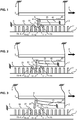
- a first example is described below with reference to the figure 1 .
- This exemplary device comprises an actuator element of the type described in the document FR 2,874,907 .
- the actuator element 3 comprises a fixed part and a movable part.
- the fixed and movable parts together form an interdigitated comb structure (known as the Anglo-Saxon "comb drive").
- the interdigitated comb structure typically comprises two combs whose teeth are separated by a single distance greater than their thickness.
- the teeth of a first comb are placed between the teeth of the second comb.
- the driving element 2 comprises a beam 23 , one end of which is connected to the movable part of the interdigitated comb structure 3, and the other end of which is connected to a driving tooth 21 .
- the driving tooth 21 is placed between two teeth 11 of the movable element 1.
- the movable part of the interdigitated comb structure 3 moves, this also moves the tooth 21 drive according to the direction and direction of movement of the movable member 1.
- the driving tooth 21 pushes or pulls then the movable member 1 via one of the teeth 11 between which the drive tooth 21 is located.
- the driving element 2 can be connected to the moving part of the actuator element 3. Thus when the moving part is set in motion, the driving element 2 is also set in motion.
- the indexing element 4 may comprise two beams 43, 45.
- a first beam 43 comprises a first free end and a second end connected to the actuator element 3, for example by the movable part.
- a second beam 45 comprises a first free end and a second end connected to a fixed frame 9 of the device.
- the first and second beams 43, 45 are interconnected by their free end.
- the indexing finger 41 of the indexing element 4 is placed in a space between two teeth 11 of the movable element 1.
- the indexing finger 41 of the indexing element 4 is moved by the actuator element 3 out of the space between the two teeth 11 of the movable element 1 to allow the moving element 1 to move.
- the indexing finger 41 is placed in the space between the teeth 11 i + 1 and 11 i + 2 , so it is moved out of these teeth, then, during the return phase be placed in the space between the teeth 11 i + 2 and 11 i + 3 .
- the operation of the device is illustrated here with a device comprising a toothed wheel as moving element 1.
- the initial position is understood as the position in which there is no electric voltage applied between the interdigitated combs of the actuator element 3.
- the direction of movement of the movable element 1 is indicated by the arrow F.
- the driving tooth 21 of the driving element 2 is positioned in the space between the two teeth 11 i and 11 i + 1 of the mobile element 1.
- the indexing finger 41 of the indexing element 4 is positioned in the space between the two teeth 11 i + 1 and 11 i + 2 .
- the indexing finger 41 prevents the mobile element 1 from moving in an uncontrolled manner in the direction of the arrow F and in the opposite direction when the actuator element 3 is at rest, for example during a shock received by the device.
- the non-return tooth 61 of the non-return element 6 is positioned in the space between the teeth 11 i + 2 and 11 i + 3 of the mobile element 1.
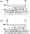
- the moving part of the actuating element 3 is moved in the direction of the arrow F.
- the driving element 2 being connected directly to the moving part of the actuating element 3, it is also moves in the direction of the arrow F and comes into contact with the tooth 11 i of the movable member 1 as shown in FIG. figure 2 .
- the second beam 45 of the indexing element 4 begins to bend thus raising the indexing finger 41.
- the moving part of the actuator element 3 moves further in the direction of the arrow F causing the indexing finger 41 of the indexing element 4 to move out of the teeth 11 i + 1 and 11 i + 2 of the movable member 1 for moving the movable member 1.
- the moving part of the actuator element 3 moves more, it pulls on the first beam 43 of the indexing element 4 which is linked fixedly to the second beam 45 of the indexing element 4 then causing the curvature of the second beam 45 away from the teeth 11 of the movable element 1.
- the displacement of the moving part of the actuator element 3 also causes the driving of the mobile element 1 by the thrust or the traction exerted by the driving tooth 21 of the driving element 2 on the tooth 11 i of the movable element 1.
- the tooth 11 i + 3 of the movable element 1 slides under the non-return tooth 61 of the non-return element 6.
- the indexing finger 41 of the indexing element 4 is positioned in the space between the teeth 11 i + 2 and 11 i + 3 of the movable element 1.
- the driving tooth 21 of the driving element 2 slides on the tooth 11 i + 1 , while the non-return finger 61 prevents movement of the movable element 1 in the opposite direction to the direction of the arrow F by abutment with the tooth 11 i + 3 .
- the actuator element 3 is a plate 32 fixed on a deformable support 8 .
- the plate 32 follows the deformations applied and undergone by the deformable support 8 .
- the plate 32 has a center of symmetry.
- the plate 32 comprises two blades 321, 322 extending longitudinally and interconnected by at least two crosspieces 323, 324 flexible (four in the Figures 6 to 10 ) each disposed on either side of the center of symmetry of the plate 32.
- Each of the two blades 321, 322 is further fixed on the support 8 deformable by a fixing member 3213, 3223 disposed at one of its ends.
- the end (or even the surrounding area) closest to the fixing element will hereinafter be referred to as the proximal end 3211, 3221.
- the end (or even the surrounding area) the most remote from the fastener will be hereinafter referred to as the distal end 3212, 3222.
- the two blades 321, 322 are interconnected by the four flexible struts 323, 324 so that a pair of struts 323, connects the proximal end 3211 of a first blade 321 to the distal end 3222 of the second blade 322 and another pair of cross members 324 connects the distal end 3212 of the first blade 321 to the proximal end 3221 of the second blade 322.
- the plate 32 then forms a mechanical oscillator which responds to deformations in compression, traction or bending of the support 8.
- the plate 32 When a compressive or tensile deformation parallel to the extension of the plate 32 is applied to the deformable support 8 , the plate 32 is also deformed in compression or in traction and the two blades 321, 322 are displaced. a relative to the other in translation along a direction of displacement parallel to their longitudinal extension. If the deformation applied is compression, the two blades 321, 322 are moved so that their distal ends 3212, 3222 move away from each other. Conversely, if the applied deformation is a pull, the two blades 321, 322 are moved so that their distal ends 3212, 3222 come closer to each other.
- the amplitude of the relative displacement of a blade 321 with respect to the other 322 depends on the distance D separating the fastening elements 3213 and 3223 from each other.
- an actuating base 7 is movably mounted on the first blade 321 and the movable member 1 is rotatably mounted on the second blade 322.
- the actuating base 7 consists of a base 71, the actuating element 2 and the indexing element 4.
- the actuating element 2 comprises a beam 23 which extends parallel to the direction of movement of the blades and has at its free end a driving tooth 21 .
- the indexing element 4 comprises a first beam 43 which extends parallel to the direction of movement of the blades and has at its free end an indexing finger 41.
- a second beam 45 extends parallel to the direction of movement of the blades. from the free end of the first beam 43 and in the opposite direction and carries on its free end a contact surface 47.
- the second blade 322 comprises a stop 3225 that contacts the contact surface 47 when the two blades 321, 322 are moved relative to each other.
- the distance separating the contact surface 47 and the stop 3225 in the rest position of the device is chosen, with respect to the space between the teeth 11 of the mobile element 1, the width of the indexing finger 41 and the initial clearance between the driving tooth 21 and the tooth to be driven of the movable element 1, so that the The movement of the indexing lever 41 out of the space between two teeth 11 of the movable element 1 takes place before the driving tooth 21 has moved the movable element 1 by a complete step.
- the device may further comprise a non-return element (not shown).
- This device is advantageously used for structural monitoring undergoing compressive, tensile and / or flexural stresses.
- this device can be fixed on a bridge pillar, the pillar then forming the support 8.
- the pitch of the teeth 11 of the movable element 1 is chosen so as to allow monitoring of the compressive deformations undergone by the pillar ( and therefore by the bridge) of a given amplitude. For example, if the pitch of the teeth 11 of the movable element 1 is 10 ⁇ m, the minimum deformation that can be detected has an amplitude of 10 ⁇ m.
- the actuator element 3 acts on the movable element 1 via the actuating element 2 to move the movable element 1 by one step. of 10 ⁇ m.
- this device can be fixed on a crane cable stressed in tension, the cable forming the support 8.
- the pitch of the teeth 11 of the movable element 1 is chosen so as to allow monitoring of the tensile strains undergone by the cable of a given amplitude. For example, if the pitch of the teeth 11 of the movable element 1 is 30 ⁇ m, the minimum deformation that can be detected has an amplitude of 30 ⁇ m.
- the actuator element 3 acts on the mobile element 1 via the actuating element 2 to move the mobile element 1 by one step. of 30 ⁇ m.
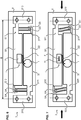
- the device is configured to monitor the tensile deformation of the support 8 (see FIG. Figures 8, 9 and 10 ).
- the operation of the device is here illustrated with a device comprising a gear as a moving element 1.
- the initial position is understood as the position in which there is no deformation generated on the deformable support.
- the direction of movement of the movable element 1 is indicated by the arrow F.
- the driving tooth 21 of the driving element 2 is positioned in the space between the two teeth 11 i and 11 i + 1 of the mobile element 1.
- the indexing finger 41 of the indexing element 4 is positioned in the space between the two teeth 11 i + 1 and 11 i + 2 .
- the indexing finger 41 prevents the mobile element 1 from moving uncontrollably in the direction of the arrow F and in the opposite direction, for example during a shock received by the device.
- the non-return tooth of the non-return element (not shown in the drawings) is positioned in another space between two teeth of the movable element 1.
- a traction force is applied to the deformable support 8 .
- the direction of the pulling force is in the direction of movement of the blades. Both blades 321, 322 are move relative to each other so that their distal ends 3212, 3222 come closer to each other.
- the result of this relative movement is the displacement of the base 71 in the direction of the arrow F.
- the driving element 2 being connected directly to the base 71, it also moves in the direction of the arrow F and comes to the contact of the tooth 11 i of the movable element 1.
- the displacement of the driving element 2 then causes the driving of the movable element 1 by the thrust or the traction exerted by the drive tooth 21.
- the amplitude of the displacement of the base 71 and the movable element 1 depends both on the deformation of the support 8 and the distance D separating the two fastening elements 3213, 3223.
- the contact surface 47 of the indexing element 4 moves toward the stop 3225 until contact is made.
- the abutment 3225 then restricts the displacement of the contact surface 47, that is to say of the free end of the second beam 45 of the indexing element 4.
- the first and second beams 43, 45 of the element indexer 4 are then deformed by bending and thus lift the indexing finger 41 out of the space between the teeth 11 i + 1 and 11 i + 2 of the movable member 1.
- the non-return element comprises a non-return tooth
- a tooth of the movable member 1 slides under the non-return tooth of the non-return element.
- the traction force on the deformable support 8 is eliminated.
- the two blades 321, 322 then move relative to each other so that their distal ends 3212, 3222 move away from each other to return to the home position.
- the result of this relative movement is the displacement of the base 71 in the opposite direction to that of the arrow F.
- the driving element 2 being connected directly to the base 71, it also moves in the opposite direction to that of the arrow F and comes into contact with the tooth 11 i + 1 of the movable member 1, slides over it to position between the teeth 11 i + 1 and 11 1 + 2 .
- the first and second beams 43, 45 of the indexing element 4 return to the rest position reducing their curvature, which causes the lowering of the indexing finger 41 and its insertion between two new teeth of the element 1.
- the return to their linear form coincides with the disengagement of the contact surface 47 of the stop 3225.
- the finger indexing 41 is arranged between two new teeth of the movable element 1.
- the indexing element 4 continues its course parallel to the direction of movement of the blades, until reaching the rest position of the device at the end of the return phase .
- the non-return element prevents a movement of the mobile element 1 in the opposite direction to the direction of the arrow F by abutment with a tooth of the movable element 1.
- all the elements of the device are found in the same position as in the initial position with an incrementation of the teeth of the movable element 1 of 1.
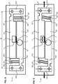
- a second variant is possible to monitor the deformation in compression of the support 8 (see Figures 6 and 7 ).
- the skilled person will then adapt the description above, and in particular the position of the various elements and their geometry for driving a movable member 1, including the geometry of the actuating tooth.
- the present invention is not limited to these two variants described above. Indeed, a person skilled in the art will be able to adapt the description to allow the bending deformation monitoring of the support 8 so that such deformation generates a displacement of the movable element 1.
- the dual indexer device is identical to the single indexer device with the interdigit comb structure described above.
- the additional elements are described below with reference to the figure 11 .
- This device with two indexing elements further comprises a second indexing element 5 comprising a second indexing finger 51 intended to be positioned intermittently between two teeth 11 of the movable element, to avoid uncontrolled movement by the element drive 2 of the movable element 1 in the direction of its displacement during the displacement phase.
- the second indexing finger 51 of the second indexing element 5 is displaced in phase opposition relative to the first indexing finger 41 of the first indexing element 4.
- the second indexing finger 51 is placed outside the teeth 11 of the movable element 1.
- the second indexing finger 51 is moved to be positioned in the space between two teeth 11 of the movable member 1, for example in the space between the two other teeth 11 of the movable member 1 in which will be positioned the first finger 41 indexing during the return phase.
- the second indexing finger 51 is moved out of the space between the two teeth 11 of the movable element 1, and preferably the second indexing finger 51 leaves room for the first finger 41 indexing.
- the second indexing element 5 can be connected to the actuator element 3 so that the actuator element 3 simultaneously moves the drive element 2 and the second indexing finger 51 .
- the second indexing element 5 may, for example, be connected to the moving part of the actuator element 3.
- the driving element 2, the first indexing element 4 and the second element indexer 5 are simultaneously moving.
- the second indexer 5 may comprise two beams 53, 55.
- a first beam 53 comprises a first free end and a second end connected to the actuator element 3, for example by the movable part.
- a second beam 55 comprises a first free end and a second end connected to the fixed frame 9 of the device.
- the first and second beams 53, 55 are interconnected by their free end.
- the operation of the device is illustrated here with a device comprising a toothed wheel as a moving element 1 and an interdigitated comb structure as an actuator element 3.
- the initial position is understood as the position in which there is no tension applied between the interdigitated combs of the actuator element 3.
- the direction of movement of the movable element 1 is indicated by the arrow F and in the opposite direction when the actuator element 3 is at rest.
- the driving tooth 21 of the driving element 2 is positioned in the space between the two teeth 11 i and 11 i + 1 of the mobile element 1.
- the first indexing finger 41 of the first indexing element 4 is positioned in the space between the two teeth 11 i + 1 and 11 i + 2 .
- the first indexing finger 41 prevents the mobile element 1 from moving in an uncontrolled manner in the direction of arrow F.
- the second indexing finger 51 of the second indexing element 5 is positioned outside the teeth 11 of the movable element 1.
- the non-return tooth 61 of the non-return element 6 is positioned in the space between the teeth 11 i + 3 and 11 i + 4 of the mobile element 1.
- the moving part of the actuating element 3 is moved in the direction of the arrow F.
- the driving element 2 being connected directly to the moving part of the actuating element 3, it is also moves in the direction of the arrow F and comes into contact with the tooth 11 i of the movable member 1 as shown in FIG. figure 12 .
- the second beam 45 of the first indexing element 4 begins to bend thus raising the first finger 41 indexing.
- the moving part of the actuator element 3 moves further in the direction of the arrow F causing the displacement of the first indexing finger 41 of the first indexing element 4 out of the teeth 11 i + 1 and 11 i + 2 of the movable element 1 for moving the movable element 1.
- the displacement of the moving part of the actuator element 3 in the direction of the arrow F also causes the displacement of the second indexing finger 51 of the second indexing element 5 to place it between the teeth 11 i + 2 and 11 i + 3 .
- the second indexing finger 51 makes it possible to control the rotation of the mobile element 1 by only allowing the latter to move in a single notch in the direction of the arrow F. If the mobile element 1 tends to move further, the second indexing 51 abuts against tooth 11 i + 3 .
- Displacements of the first and second indexing fingers 41 and 51 are in opposition to the phase. This is made possible in the example illustrated by the Figures 11 to 15 thanks to the direct attachment of the first beam 43 of the first indexing element 4 to the moving part of the actuator element 3 on an edge located on the same side as the tip of the arrow F, the direct attachment of the first beam 53 of the second indexing element 5 to the movable part of the actuator element 3 on an edge positioned on the opposite side to the tip of the arrow F, and the fixed connection of the second beams 45 and 55 to the frame 9 and the first beams 43 and 53 respectively.
- the displacement of the moving part of the actuator element 3 also causes the driving of the mobile element 1 by the thrust or the traction exerted by the driving tooth 21 of the driving element 2 on the tooth 11 i of the movable element 1.
- the tooth 11 i + 4 of the movable element 1 slides under the non-return tooth 61 of the non-return element 6.
- the first indexing finger 41 of the first indexing element 4 is positioned in the space between the teeth 11 i + 2 and 11 i + 3 of the movable element 1.
- the driving tooth 21 of the driving element 2 slides on the tooth 11 i + 1 , and the second indexing member 51 of the second indexing element 5 is moved away from the teeth 11 of the movable element 1, while the non-return finger 61 prevents a moving the movable element 1 in the opposite direction to the direction of the arrow F by abutment with the tooth 11 i + 4 .
Landscapes
- Engineering & Computer Science (AREA)
- General Engineering & Computer Science (AREA)
- Physics & Mathematics (AREA)
- General Physics & Mathematics (AREA)
- Theoretical Computer Science (AREA)
- Mechanical Engineering (AREA)
- Micromachines (AREA)
- Transmission Devices (AREA)
Claims (10)
- Vorrichtung, die Folgendes umfasst:- ein bewegliches Element (1) mit Zähnen (11; 11i, 11i+1, 11i+2, 11i+3, 11i+4) und das in Bewegung gesetzt werden soll;- ein Antriebselement (2), das in die Zähne (11; 11i, 11i+1, 11i+2, 11i+3, 11i+4) des beweglichen Elements (1) eingreifen soll, um das bewegliche Element (1) in einer Bewegungsrichtung in Bewegung zu setzen;- ein Betätigungselement (3), das angepasst ist, eine Wechselbewegung zu erzeugen, um das Antriebselement (2) nach zumindest zwei Phasen, einer Antriebsphase und einer Rückkehrphase, zu bewegen,
bei der Antriebsphase greift das Antriebselement (2) mit zumindest einem Zahn (11; 11i, 11i+1, 11i+2, 11i+3, 11i+4) des beweglichen Elements (1) ein, um das bewegliche Element (1) zu schieben oder zu ziehen,
bei der Rückkehrphase ohne Antrieb ist das Antriebselement (2) gegenüber dem beweglichen Element (1) bewegt, um mit zumindest einem anderen Zahn (11; 11i, 11i+1, 11i+2, 11i+3, 11i+4) des beweglichen Elements (1) zu greifen,- ein erstes Indexerelement (4), das einen ersten Indexierfinger (41) umfasst, der intermittierend in einen Raum zwischen zwei Zähnen (11; 11i, 11i+1, 11i+2, 11i+3, 11i+4) des beweglichen Elements (1) positioniert werden soll, um eine unkontrollierte Bewegung durch das Antriebselement in der Bewegungsrichtung des beweglichen Elements oder in entgegengesetzter Richtung zu verhindern;dadurch gekennzeichnet, dass
das erste Indexierelement (4) mit dem Betätigungselement (3) verbunden ist, so dass das Betätigungselement (3) gleichzeitig das Antriebselement (2) und den ersten Indexierfinger (41) bewegt,
wobei das Betätigungselement (3) einen feststehenden Teil und einen gegenüber dem feststehenden Teil beweglichen Teil umfasst, das Antriebselement (2) und das Indexierelement (4) mit dem beweglichen Teil verbunden sind, und
das erste Indexierelement (4) Folgendes umfasst:- einen ersten Balken (43) umfassend ein erstes freies Ende und ein zweites Ende, das mit dem Betätigungselement (3) verbunden ist; und- einen zweiten Balken (45) umfassend ein erstes freies Ende und ein Ende, das mit einem feststehenden Rahmen (9) der Vorrichtung verbunden ist;wobei der erste Balken (43) und der zweite Balken (45) mit ihren jeweiligen freien Enden miteinander verbunden sind, so dass eine durch das Antriebselement (3) angetriebene Bewegung des ersten Balkens (43) eine Biegung des zweiten Balkens (45) auslöst, was zur Wirkung hat, den ersten Indexierfinger (41) gegenüber dem beweglichen Element (1) zu bewegen. - Vorrichtung nach Anspruch 1, wobei der erste Indexierfinger (41) und das Betätigungselement (3) so konfiguriert sind, dass:bei der Antriebsphase der erste Indexierfinger (41) durch das Betätigungselement (3) aus dem Raum zwischen den beiden Zähnen (11; 11i, 11i+1, 11i+2, 11i+3, 11i+4) des beweglichen Elements (1) bewegt wird; undbei der Rückkehrphase der erste Indexierfinger (41) durch das Betätigungselement (3) in einen anderen Raum zwischen zwei anderen Zähnen (11; 11i, 11i+1, 11i+2, 11i+3, 11i+4) des beweglichen Elements (1) positioniert wird.
- Vorrichtung nach einem der Ansprüche 1 und 2, das ferner ein zweites Indexierelement (5) umfasst, das einen zweiten Indexierfinger (51) enthält, der intermittierend zwischen zwei Zähnen (11; 11i, 11i+1, 11i+2, 11i+3, 11i+4) des beweglichen Elements (1) positioniert werden soll, wobei der zweite Indexierfinger (51) in entgegengesetzter Phase zum ersten Indexierfinger (41) bewegt wird.
- Vorrichtung nach Anspruch 3, wobei der zweite Indexierfinger (51) des Betätigungselements (3) so konfiguriert sind, dass:bei der Antriebsphase der zweite Indexierfinger (51) in den Raum zwischen den beiden anderen Zähnen (11; 11i, 11i+1, 11i+2, 11i+3, 11i+4) des beweglichen Elements (1) positioniert wird, in den der erste Indexierfinger (41) in der Rückkehrphase positioniert wird; undbei der Rückkehrphase wird der zweite Indexierfinger (51) aus dem Raum zwischen den beiden Zähnen (11; 11i, 11i+1, 11i+2, 11i+3, 11i+4) des beweglichen Elements (1) bewegt.
- Vorrichtung nach einem der Ansprüche 3 oder 4, wobei das zweite Indexierelement (5) ebenfalls mit dem Betätigungselement (3) verbunden ist, so dass das Betätigungselement (3) gleichzeitig das Antriebselement (2) und den zweiten Indexierfinger (51) bewegt.
- Vorrichtung nach einem der vorstehenden Ansprüche 3 bis 5, wobei der zweite Indexerelement (5) Folgendes umfasst:- einen ersten Balken (53) umfassend ein erstes freies Ende und ein zweites Ende, das mit dem Betätigungselement (3) verbunden ist; und- einen zweiten Balken (55) umfassend ein erstes freies Ende und ein Ende, das mit dem feststehenden Rahmen (9) der Vorrichtung verbunden ist;wobei der erste Balken (53) und der zweite Balken (55) mit ihren jeweiligen freien Enden miteinander verbunden sind, so dass eine durch das Antriebselement (3) angetriebene Bewegung des ersten Balkens (53) eine Biegung des zweiten Balkens (55) auslöst, was zur Wirkung hat, den ersten Indexierfinger (51) gegenüber dem beweglichen Element (1) zu bewegen.
- Vorrichtung nach Anspruch 1 oder 2, wobei das Betätigungselement (3) eine Platte (32) umfasst, die sich in einer Längsrichtung erstreckt und auf einem Träger (8) befestigt werden muss,
wobei die Platte (32) zwei Klingen (321, 322) umfasst, die durch zumindest zwei flexible Stege (323, 324) miteinander verbunden sind und auf dem Träger zu befestigen sind, so dass eine Verformung unter Druck oder Zug des Trägers (8) eine Bewegung einer Klinge gegenüber der anderen in eine Bewegungsrichtung parallel zur Längsrichtung der Platte (32) erzeugt. - Vorrichtung nach Anspruch 7, wobei jede der Klingen (321, 322) ein proximales Ende (3211, 3221) und ein distales Ende (3212, 3222) umfasst,
wobei jede der Klingen (321, 322) an ihrem proximalen Ende (3211, 3221) ein Befestigungselement (3213, 3223) für die Befestigung am Träger (8) umfasst, und
wobei eine flexible Querstrebe (323, 324) das distale Ende (3212, 3222) einer Klinge (321, 322) mit dem proximalen Ende (3221, 3211) der anderen Klinge (322, 321) verbindet. - Vorrichtung nach Anspruch 7 oder 8, die ferner Folgendes umfasst ein Betätigungsmodul (7), das auf einer der Klingen (321) befestigt ist, wobei das bewegliche Element (1) drehbar auf der anderen Klinge (322) der Platte befestigt ist,
wobei das Betätigungsmodul (7) eine Basis (71), das Betätigungselement (3) und das Indexierelement (4) umfasst. - Vorrichtung nach Anspruch 9, wobei das Betätigungselement (3) einen Balken (23) umfasst, der sich parallel zur Bewegungsrichtung der Klingen erstreckt und an seinem freien Ende einen Antriebszahn (21) aufweist,
wobei das Indexierelement (4) einen ersten Balken (43) umfasst, der sich parallel zur Bewegungsrichtung der Klingen erstreckt und an seinem freien Ende einen Indexierfinger (41) aufweist, und einen zweiten Balken (45), der sich parallel zur Bewegungsrichtung der Klingen ab dem freien Ende des ersten Balkens (43) und in entgegengesetzter Richtung erstreckt und an seinem freien Ende eine Kontaktfläche (47) trägt,
wobei die zweite Klinge (322) einen Anschlag (3225) umfasst, der bei der Bewegungsaufnahme der Klingen zueinander von der Kontaktfläche (47) berührt werden soll, um den ersten Indexierfinger (41) des beweglichen Elements (1) zu entfernen.
Applications Claiming Priority (2)
| Application Number | Priority Date | Filing Date | Title |
|---|---|---|---|
| FR1250320A FR2985721B1 (fr) | 2012-01-12 | 2012-01-12 | Indexation passive d'un element mobile presentant des dents |
| PCT/EP2013/050442 WO2013104738A1 (fr) | 2012-01-12 | 2013-01-11 | Indexation passive d'un élément mobile présentant des dents |
Publications (2)
| Publication Number | Publication Date |
|---|---|
| EP2802852A1 EP2802852A1 (de) | 2014-11-19 |
| EP2802852B1 true EP2802852B1 (de) | 2017-10-04 |
Family
ID=47553085
Family Applications (1)
| Application Number | Title | Priority Date | Filing Date |
|---|---|---|---|
| EP13700171.5A Active EP2802852B1 (de) | 2012-01-12 | 2013-01-11 | Passive indexierung eines beweglichen elements mit zähnen |
Country Status (5)
| Country | Link |
|---|---|
| US (1) | US9882510B2 (de) |
| EP (1) | EP2802852B1 (de) |
| JP (1) | JP6358956B2 (de) |
| FR (1) | FR2985721B1 (de) |
| WO (1) | WO2013104738A1 (de) |
Families Citing this family (4)
| Publication number | Priority date | Publication date | Assignee | Title |
|---|---|---|---|---|
| FR3048500B1 (fr) | 2016-03-02 | 2018-03-02 | Etat Francais Represente Par Le Delegue General Pour L'armement | Capteur de deformation permettant une discrimination de mesure en fonction de la direction de la deformation |
| DE102016220111B3 (de) * | 2016-10-14 | 2018-02-01 | Hahn-Schickard-Gesellschaft für angewandte Forschung e.V. | Grenzwertdetektionsvorrichtung |
| DE102019122671B4 (de) | 2019-08-22 | 2024-06-20 | RUHR-UNIVERSITäT BOCHUM | Passiver mikromechanischer Zähler |
| EP4354082A3 (de) * | 2019-11-18 | 2024-06-12 | Philip Schmitt | Mikromechanische vorrichtung zur energieautarken messung und speicherung eines mechanischen verschiebungssignals |
Family Cites Families (9)
| Publication number | Priority date | Publication date | Assignee | Title |
|---|---|---|---|---|
| FR591217A (fr) * | 1924-12-29 | 1925-06-30 | Compteurs De Voitures Taximetr | Dispositif de sécurité pour mécanisme à déclics |
| FR695379A (fr) * | 1929-10-24 | 1930-12-16 | Dispositif pour l'avancement pas à pas des compteurs | |
| CH497725A (de) * | 1962-01-31 | 1964-12-31 | Straumann Inst Ag | Antrieb für ein mit tonfrequenten, translatorischen Oszillationen angetriebenes Zeitmessgerät |
| JPS5319105B2 (de) * | 1972-05-20 | 1978-06-19 | ||
| CH626495B (fr) * | 1977-05-02 | Universo Sa | Dispositif moteur pour garde-temps a affichage analogique. | |
| FR2874907B1 (fr) | 2004-09-03 | 2006-11-24 | Silmach Soc Par Actions Simpli | Dispositif d'entrainement, notamment pour mecanisme horloger |
| FR2883277B1 (fr) * | 2005-03-18 | 2007-05-11 | Silmach Soc Par Actions Simpli | Procede et dispositif pour deplacer un element a entrainer utilisant un element actionneur forme par gravure dans un materiau semi-conducteur |
| JP2006325323A (ja) * | 2005-05-18 | 2006-11-30 | Pioneer Electronic Corp | 駆動装置 |
| EP2177960B1 (de) * | 2008-10-16 | 2011-12-21 | ETA SA Manufacture Horlogère Suisse | Blockiermechanismus für Modul eines Uhrwerksantriebs |
-
2012
- 2012-01-12 FR FR1250320A patent/FR2985721B1/fr not_active Expired - Fee Related
-
2013
- 2013-01-11 JP JP2014551621A patent/JP6358956B2/ja not_active Expired - Fee Related
- 2013-01-11 WO PCT/EP2013/050442 patent/WO2013104738A1/fr not_active Ceased
- 2013-01-11 EP EP13700171.5A patent/EP2802852B1/de active Active
- 2013-01-11 US US14/371,726 patent/US9882510B2/en active Active
Non-Patent Citations (1)
| Title |
|---|
| None * |
Also Published As
| Publication number | Publication date |
|---|---|
| JP2015507460A (ja) | 2015-03-05 |
| US9882510B2 (en) | 2018-01-30 |
| EP2802852A1 (de) | 2014-11-19 |
| WO2013104738A1 (fr) | 2013-07-18 |
| JP6358956B2 (ja) | 2018-07-18 |
| FR2985721B1 (fr) | 2017-04-07 |
| US20150022053A1 (en) | 2015-01-22 |
| FR2985721A1 (fr) | 2013-07-19 |
Similar Documents
| Publication | Publication Date | Title |
|---|---|---|
| EP2802852B1 (de) | Passive indexierung eines beweglichen elements mit zähnen | |
| EP2135305B1 (de) | Feineinstellungssystem mit trägheitsmotor auf der basis eines mechanischen verstärkers | |
| EP3559755B1 (de) | Flexible monolithisches bauteil für uhren | |
| FR2982922A1 (fr) | Systeme de frein d'arbre rotatif, en particulier pour rotor ou helice d'aeronefs, comportant un actionneur lineaire | |
| EP1599766B1 (de) | Herstellungsverfahren einer mems einrichtung | |
| WO2014072317A2 (fr) | Procédé de réalisation d'un élément flexible multistable | |
| WO2014037319A1 (fr) | Ancre flexible à force constante | |
| CH709512B1 (fr) | Dispositif d'entraînement de mems bidirectionnel. | |
| WO2013072615A1 (fr) | Module indicateur pour tableau de bord a mouvement fluide | |
| EP2677372B1 (de) | Rad mit Spielnachstellung | |
| EP2864167A1 (de) | Elektrischer bremskraftverstärker mit getriebespielausgleich | |
| EP2736161B1 (de) | Betätigungsvorrichtung mit durch Kriechbewegung ausgelöstem Antriebselement | |
| EP1998144A2 (de) | Vorrichtung zur Übertragung einer relativen Bewegung zwischen einem zweiten und einem dritten Element eines Systems an ein erstes bewegliches Element mit Zähnen | |
| EP2422114B1 (de) | Drehmomentbegrenzer, insbesondere für einen aktuator der gondel eines flugzeugturbostrahltriebwerks | |
| EP3037381B1 (de) | Vorrichtung zur umwandlung einer bewegung aus der ebene in eine bewegung in der ebene bzw. umgekehrt | |
| FR2946970A1 (fr) | Dispositif micromecanique d'amplification d'un mouvement vibratoire | |
| EP3537593B1 (de) | Rotationsvorrichtung für ein zahnrad | |
| CH697381B1 (fr) | Mécanisme comprenant un premier mobile en contact ou destiné à venir en contact avec un deuxième élément. | |
| EP1921522A1 (de) | Anordnung zur mechanischen Verbindung eines MEMS-Mikromotors mit einem Uhrrädchen und diese Anordnung umfassende Uhr | |
| WO2018046563A1 (fr) | Mecanisme d'echappement | |
| FR3072792B1 (fr) | Systeme de positionnement adapte a un fonctionnement a basses temperatures | |
| EP3804117A1 (de) | System zur schwingungsenergierückgewinnung | |
| EP2735923A1 (de) | Zeigerantriebsmechanismus einer elektromechanischen Uhr, der mit einer Verriegelung ausgestattet ist | |
| CH714734A2 (fr) | Dispositif de rotation d’une roue dentée. | |
| CH706670A2 (fr) | Roue d'horlogerie à rattrapage de jeu. |
Legal Events
| Date | Code | Title | Description |
|---|---|---|---|
| PUAI | Public reference made under article 153(3) epc to a published international application that has entered the european phase |
Free format text: ORIGINAL CODE: 0009012 |
|
| 17P | Request for examination filed |
Effective date: 20140808 |
|
| AK | Designated contracting states |
Kind code of ref document: A1 Designated state(s): AL AT BE BG CH CY CZ DE DK EE ES FI FR GB GR HR HU IE IS IT LI LT LU LV MC MK MT NL NO PL PT RO RS SE SI SK SM TR |
|
| DAX | Request for extension of the european patent (deleted) | ||
| REG | Reference to a national code |
Ref country code: DE Ref legal event code: R079 Ref document number: 602013027418 Country of ref document: DE Free format text: PREVIOUS MAIN CLASS: G01M0001040000 Ipc: G06M0001040000 |
|
| GRAP | Despatch of communication of intention to grant a patent |
Free format text: ORIGINAL CODE: EPIDOSNIGR1 |
|
| RIC1 | Information provided on ipc code assigned before grant |
Ipc: F16H 31/00 20060101ALI20161011BHEP Ipc: G04C 3/00 20060101ALI20161011BHEP Ipc: G06M 1/04 20060101AFI20161011BHEP Ipc: H02N 1/00 20060101ALI20161011BHEP |
|
| INTG | Intention to grant announced |
Effective date: 20161024 |
|
| GRAS | Grant fee paid |
Free format text: ORIGINAL CODE: EPIDOSNIGR3 |
|
| GRAJ | Information related to disapproval of communication of intention to grant by the applicant or resumption of examination proceedings by the epo deleted |
Free format text: ORIGINAL CODE: EPIDOSDIGR1 |
|
| GRAL | Information related to payment of fee for publishing/printing deleted |
Free format text: ORIGINAL CODE: EPIDOSDIGR3 |
|
| INTC | Intention to grant announced (deleted) | ||
| GRAP | Despatch of communication of intention to grant a patent |
Free format text: ORIGINAL CODE: EPIDOSNIGR1 |
|
| INTG | Intention to grant announced |
Effective date: 20170420 |
|
| GRAA | (expected) grant |
Free format text: ORIGINAL CODE: 0009210 |
|
| AK | Designated contracting states |
Kind code of ref document: B1 Designated state(s): AL AT BE BG CH CY CZ DE DK EE ES FI FR GB GR HR HU IE IS IT LI LT LU LV MC MK MT NL NO PL PT RO RS SE SI SK SM TR |
|
| REG | Reference to a national code |
Ref country code: GB Ref legal event code: FG4D Free format text: NOT ENGLISH |
|
| REG | Reference to a national code |
Ref country code: CH Ref legal event code: EP |
|
| REG | Reference to a national code |
Ref country code: AT Ref legal event code: REF Ref document number: 934680 Country of ref document: AT Kind code of ref document: T Effective date: 20171015 |
|
| REG | Reference to a national code |
Ref country code: IE Ref legal event code: FG4D Free format text: LANGUAGE OF EP DOCUMENT: FRENCH |
|
| REG | Reference to a national code |
Ref country code: DE Ref legal event code: R096 Ref document number: 602013027418 Country of ref document: DE |
|
| REG | Reference to a national code |
Ref country code: FR Ref legal event code: PLFP Year of fee payment: 6 |
|
| REG | Reference to a national code |
Ref country code: NL Ref legal event code: MP Effective date: 20171004 |
|
| REG | Reference to a national code |
Ref country code: LT Ref legal event code: MG4D |
|
| REG | Reference to a national code |
Ref country code: AT Ref legal event code: MK05 Ref document number: 934680 Country of ref document: AT Kind code of ref document: T Effective date: 20171004 |
|
| PG25 | Lapsed in a contracting state [announced via postgrant information from national office to epo] |
Ref country code: NL Free format text: LAPSE BECAUSE OF FAILURE TO SUBMIT A TRANSLATION OF THE DESCRIPTION OR TO PAY THE FEE WITHIN THE PRESCRIBED TIME-LIMIT Effective date: 20171004 |
|
| PG25 | Lapsed in a contracting state [announced via postgrant information from national office to epo] |
Ref country code: LT Free format text: LAPSE BECAUSE OF FAILURE TO SUBMIT A TRANSLATION OF THE DESCRIPTION OR TO PAY THE FEE WITHIN THE PRESCRIBED TIME-LIMIT Effective date: 20171004 Ref country code: NO Free format text: LAPSE BECAUSE OF FAILURE TO SUBMIT A TRANSLATION OF THE DESCRIPTION OR TO PAY THE FEE WITHIN THE PRESCRIBED TIME-LIMIT Effective date: 20180104 Ref country code: SE Free format text: LAPSE BECAUSE OF FAILURE TO SUBMIT A TRANSLATION OF THE DESCRIPTION OR TO PAY THE FEE WITHIN THE PRESCRIBED TIME-LIMIT Effective date: 20171004 Ref country code: FI Free format text: LAPSE BECAUSE OF FAILURE TO SUBMIT A TRANSLATION OF THE DESCRIPTION OR TO PAY THE FEE WITHIN THE PRESCRIBED TIME-LIMIT Effective date: 20171004 |
|
| PG25 | Lapsed in a contracting state [announced via postgrant information from national office to epo] |
Ref country code: AT Free format text: LAPSE BECAUSE OF FAILURE TO SUBMIT A TRANSLATION OF THE DESCRIPTION OR TO PAY THE FEE WITHIN THE PRESCRIBED TIME-LIMIT Effective date: 20171004 Ref country code: RS Free format text: LAPSE BECAUSE OF FAILURE TO SUBMIT A TRANSLATION OF THE DESCRIPTION OR TO PAY THE FEE WITHIN THE PRESCRIBED TIME-LIMIT Effective date: 20171004 Ref country code: BG Free format text: LAPSE BECAUSE OF FAILURE TO SUBMIT A TRANSLATION OF THE DESCRIPTION OR TO PAY THE FEE WITHIN THE PRESCRIBED TIME-LIMIT Effective date: 20180104 Ref country code: LV Free format text: LAPSE BECAUSE OF FAILURE TO SUBMIT A TRANSLATION OF THE DESCRIPTION OR TO PAY THE FEE WITHIN THE PRESCRIBED TIME-LIMIT Effective date: 20171004 Ref country code: GR Free format text: LAPSE BECAUSE OF FAILURE TO SUBMIT A TRANSLATION OF THE DESCRIPTION OR TO PAY THE FEE WITHIN THE PRESCRIBED TIME-LIMIT Effective date: 20180105 Ref country code: HR Free format text: LAPSE BECAUSE OF FAILURE TO SUBMIT A TRANSLATION OF THE DESCRIPTION OR TO PAY THE FEE WITHIN THE PRESCRIBED TIME-LIMIT Effective date: 20171004 Ref country code: IS Free format text: LAPSE BECAUSE OF FAILURE TO SUBMIT A TRANSLATION OF THE DESCRIPTION OR TO PAY THE FEE WITHIN THE PRESCRIBED TIME-LIMIT Effective date: 20180204 |
|
| REG | Reference to a national code |
Ref country code: DE Ref legal event code: R097 Ref document number: 602013027418 Country of ref document: DE |
|
| PG25 | Lapsed in a contracting state [announced via postgrant information from national office to epo] |
Ref country code: DK Free format text: LAPSE BECAUSE OF FAILURE TO SUBMIT A TRANSLATION OF THE DESCRIPTION OR TO PAY THE FEE WITHIN THE PRESCRIBED TIME-LIMIT Effective date: 20171004 Ref country code: CZ Free format text: LAPSE BECAUSE OF FAILURE TO SUBMIT A TRANSLATION OF THE DESCRIPTION OR TO PAY THE FEE WITHIN THE PRESCRIBED TIME-LIMIT Effective date: 20171004 Ref country code: EE Free format text: LAPSE BECAUSE OF FAILURE TO SUBMIT A TRANSLATION OF THE DESCRIPTION OR TO PAY THE FEE WITHIN THE PRESCRIBED TIME-LIMIT Effective date: 20171004 Ref country code: SK Free format text: LAPSE BECAUSE OF FAILURE TO SUBMIT A TRANSLATION OF THE DESCRIPTION OR TO PAY THE FEE WITHIN THE PRESCRIBED TIME-LIMIT Effective date: 20171004 |
|
| PLBE | No opposition filed within time limit |
Free format text: ORIGINAL CODE: 0009261 |
|
| STAA | Information on the status of an ep patent application or granted ep patent |
Free format text: STATUS: NO OPPOSITION FILED WITHIN TIME LIMIT |
|
| PG25 | Lapsed in a contracting state [announced via postgrant information from national office to epo] |
Ref country code: IT Free format text: LAPSE BECAUSE OF FAILURE TO SUBMIT A TRANSLATION OF THE DESCRIPTION OR TO PAY THE FEE WITHIN THE PRESCRIBED TIME-LIMIT Effective date: 20171004 Ref country code: RO Free format text: LAPSE BECAUSE OF FAILURE TO SUBMIT A TRANSLATION OF THE DESCRIPTION OR TO PAY THE FEE WITHIN THE PRESCRIBED TIME-LIMIT Effective date: 20171004 Ref country code: SM Free format text: LAPSE BECAUSE OF FAILURE TO SUBMIT A TRANSLATION OF THE DESCRIPTION OR TO PAY THE FEE WITHIN THE PRESCRIBED TIME-LIMIT Effective date: 20171004 Ref country code: PL Free format text: LAPSE BECAUSE OF FAILURE TO SUBMIT A TRANSLATION OF THE DESCRIPTION OR TO PAY THE FEE WITHIN THE PRESCRIBED TIME-LIMIT Effective date: 20171004 |
|
| REG | Reference to a national code |
Ref country code: CH Ref legal event code: PL |
|
| 26N | No opposition filed |
Effective date: 20180705 |
|
| PG25 | Lapsed in a contracting state [announced via postgrant information from national office to epo] |
Ref country code: MT Free format text: LAPSE BECAUSE OF FAILURE TO SUBMIT A TRANSLATION OF THE DESCRIPTION OR TO PAY THE FEE WITHIN THE PRESCRIBED TIME-LIMIT Effective date: 20171004 |
|
| PG25 | Lapsed in a contracting state [announced via postgrant information from national office to epo] |
Ref country code: LU Free format text: LAPSE BECAUSE OF NON-PAYMENT OF DUE FEES Effective date: 20180111 |
|
| REG | Reference to a national code |
Ref country code: IE Ref legal event code: MM4A |
|
| PG25 | Lapsed in a contracting state [announced via postgrant information from national office to epo] |
Ref country code: CH Free format text: LAPSE BECAUSE OF NON-PAYMENT OF DUE FEES Effective date: 20180131 Ref country code: SI Free format text: LAPSE BECAUSE OF FAILURE TO SUBMIT A TRANSLATION OF THE DESCRIPTION OR TO PAY THE FEE WITHIN THE PRESCRIBED TIME-LIMIT Effective date: 20171004 Ref country code: LI Free format text: LAPSE BECAUSE OF NON-PAYMENT OF DUE FEES Effective date: 20180131 |
|
| PG25 | Lapsed in a contracting state [announced via postgrant information from national office to epo] |
Ref country code: IE Free format text: LAPSE BECAUSE OF NON-PAYMENT OF DUE FEES Effective date: 20180111 |
|
| PG25 | Lapsed in a contracting state [announced via postgrant information from national office to epo] |
Ref country code: MC Free format text: LAPSE BECAUSE OF FAILURE TO SUBMIT A TRANSLATION OF THE DESCRIPTION OR TO PAY THE FEE WITHIN THE PRESCRIBED TIME-LIMIT Effective date: 20171004 |
|
| PG25 | Lapsed in a contracting state [announced via postgrant information from national office to epo] |
Ref country code: ES Free format text: LAPSE BECAUSE OF FAILURE TO SUBMIT A TRANSLATION OF THE DESCRIPTION OR TO PAY THE FEE WITHIN THE PRESCRIBED TIME-LIMIT Effective date: 20171004 |
|
| PG25 | Lapsed in a contracting state [announced via postgrant information from national office to epo] |
Ref country code: TR Free format text: LAPSE BECAUSE OF FAILURE TO SUBMIT A TRANSLATION OF THE DESCRIPTION OR TO PAY THE FEE WITHIN THE PRESCRIBED TIME-LIMIT Effective date: 20171004 |
|
| PG25 | Lapsed in a contracting state [announced via postgrant information from national office to epo] |
Ref country code: PT Free format text: LAPSE BECAUSE OF FAILURE TO SUBMIT A TRANSLATION OF THE DESCRIPTION OR TO PAY THE FEE WITHIN THE PRESCRIBED TIME-LIMIT Effective date: 20171004 Ref country code: HU Free format text: LAPSE BECAUSE OF FAILURE TO SUBMIT A TRANSLATION OF THE DESCRIPTION OR TO PAY THE FEE WITHIN THE PRESCRIBED TIME-LIMIT; INVALID AB INITIO Effective date: 20130111 |
|
| PG25 | Lapsed in a contracting state [announced via postgrant information from national office to epo] |
Ref country code: CY Free format text: LAPSE BECAUSE OF FAILURE TO SUBMIT A TRANSLATION OF THE DESCRIPTION OR TO PAY THE FEE WITHIN THE PRESCRIBED TIME-LIMIT Effective date: 20171004 Ref country code: MK Free format text: LAPSE BECAUSE OF NON-PAYMENT OF DUE FEES Effective date: 20171004 |
|
| PG25 | Lapsed in a contracting state [announced via postgrant information from national office to epo] |
Ref country code: AL Free format text: LAPSE BECAUSE OF FAILURE TO SUBMIT A TRANSLATION OF THE DESCRIPTION OR TO PAY THE FEE WITHIN THE PRESCRIBED TIME-LIMIT Effective date: 20171004 |
|
| PGFP | Annual fee paid to national office [announced via postgrant information from national office to epo] |
Ref country code: GB Payment date: 20230123 Year of fee payment: 11 Ref country code: DE Payment date: 20230112 Year of fee payment: 11 Ref country code: BE Payment date: 20230117 Year of fee payment: 11 |
|
| REG | Reference to a national code |
Ref country code: DE Ref legal event code: R119 Ref document number: 602013027418 Country of ref document: DE |
|
| GBPC | Gb: european patent ceased through non-payment of renewal fee |
Effective date: 20240111 |
|
| PG25 | Lapsed in a contracting state [announced via postgrant information from national office to epo] |
Ref country code: DE Free format text: LAPSE BECAUSE OF NON-PAYMENT OF DUE FEES Effective date: 20240801 |
|
| PG25 | Lapsed in a contracting state [announced via postgrant information from national office to epo] |
Ref country code: GB Free format text: LAPSE BECAUSE OF NON-PAYMENT OF DUE FEES Effective date: 20240111 |
|
| PG25 | Lapsed in a contracting state [announced via postgrant information from national office to epo] |
Ref country code: BE Free format text: LAPSE BECAUSE OF NON-PAYMENT OF DUE FEES Effective date: 20240131 |
|
| PG25 | Lapsed in a contracting state [announced via postgrant information from national office to epo] |
Ref country code: GB Free format text: LAPSE BECAUSE OF NON-PAYMENT OF DUE FEES Effective date: 20240111 Ref country code: DE Free format text: LAPSE BECAUSE OF NON-PAYMENT OF DUE FEES Effective date: 20240801 Ref country code: BE Free format text: LAPSE BECAUSE OF NON-PAYMENT OF DUE FEES Effective date: 20240131 |
|
| REG | Reference to a national code |
Ref country code: BE Ref legal event code: MM Effective date: 20240131 |
|
| PGFP | Annual fee paid to national office [announced via postgrant information from national office to epo] |
Ref country code: FR Payment date: 20251224 Year of fee payment: 14 |