EP1998086B1 - Joint plat métallique - Google Patents
Joint plat métallique Download PDFInfo
- Publication number
- EP1998086B1 EP1998086B1 EP07010816.2A EP07010816A EP1998086B1 EP 1998086 B1 EP1998086 B1 EP 1998086B1 EP 07010816 A EP07010816 A EP 07010816A EP 1998086 B1 EP1998086 B1 EP 1998086B1
- Authority
- EP
- European Patent Office
- Prior art keywords
- gasket
- gasket layer
- metallic flat
- layer
- sealing
- Prior art date
- Legal status (The legal status is an assumption and is not a legal conclusion. Google has not performed a legal analysis and makes no representation as to the accuracy of the status listed.)
- Active
Links
- 239000002184 metal Substances 0.000 title claims description 15
- 238000007789 sealing Methods 0.000 claims description 136
- 238000002485 combustion reaction Methods 0.000 claims description 71
- 239000011324 bead Substances 0.000 claims description 55
- 229920001971 elastomer Polymers 0.000 claims description 22
- 239000000806 elastomer Substances 0.000 claims description 21
- 239000000463 material Substances 0.000 claims description 14
- 238000007906 compression Methods 0.000 claims description 6
- 230000006835 compression Effects 0.000 claims description 4
- 239000002826 coolant Substances 0.000 claims description 4
- 229910000975 Carbon steel Inorganic materials 0.000 claims description 3
- 229910000639 Spring steel Inorganic materials 0.000 claims description 3
- 239000000314 lubricant Substances 0.000 claims description 3
- 229910001220 stainless steel Inorganic materials 0.000 claims description 2
- 239000010962 carbon steel Substances 0.000 claims 1
- 239000010935 stainless steel Substances 0.000 claims 1
- 239000010410 layer Substances 0.000 description 115
- 238000013461 design Methods 0.000 description 6
- 239000004033 plastic Substances 0.000 description 6
- 229920003023 plastic Polymers 0.000 description 6
- 238000012876 topography Methods 0.000 description 6
- 238000000576 coating method Methods 0.000 description 5
- 238000003466 welding Methods 0.000 description 5
- 229910000831 Steel Inorganic materials 0.000 description 4
- 230000015572 biosynthetic process Effects 0.000 description 4
- 239000011248 coating agent Substances 0.000 description 4
- 238000010276 construction Methods 0.000 description 4
- 238000004519 manufacturing process Methods 0.000 description 4
- 239000010959 steel Substances 0.000 description 4
- 239000000498 cooling water Substances 0.000 description 3
- 238000004049 embossing Methods 0.000 description 3
- 238000005259 measurement Methods 0.000 description 3
- 239000000243 solution Substances 0.000 description 3
- 239000006228 supernatant Substances 0.000 description 3
- KUDUQBURMYMBIJ-UHFFFAOYSA-N 2-prop-2-enoyloxyethyl prop-2-enoate Chemical compound C=CC(=O)OCCOC(=O)C=C KUDUQBURMYMBIJ-UHFFFAOYSA-N 0.000 description 2
- 239000005062 Polybutadiene Substances 0.000 description 2
- NIXOWILDQLNWCW-UHFFFAOYSA-N acrylic acid group Chemical group C(C=C)(=O)O NIXOWILDQLNWCW-UHFFFAOYSA-N 0.000 description 2
- 238000004026 adhesive bonding Methods 0.000 description 2
- 230000008859 change Effects 0.000 description 2
- 239000012141 concentrate Substances 0.000 description 2
- 238000003780 insertion Methods 0.000 description 2
- 230000037431 insertion Effects 0.000 description 2
- 230000001788 irregular Effects 0.000 description 2
- 238000000034 method Methods 0.000 description 2
- 229920002857 polybutadiene Polymers 0.000 description 2
- 239000004814 polyurethane Substances 0.000 description 2
- 230000036316 preload Effects 0.000 description 2
- 230000000630 rising effect Effects 0.000 description 2
- 238000000926 separation method Methods 0.000 description 2
- 229920002725 thermoplastic elastomer Polymers 0.000 description 2
- 230000008719 thickening Effects 0.000 description 2
- 229920002943 EPDM rubber Polymers 0.000 description 1
- 229920000181 Ethylene propylene rubber Polymers 0.000 description 1
- 230000009471 action Effects 0.000 description 1
- 230000006978 adaptation Effects 0.000 description 1
- 238000013459 approach Methods 0.000 description 1
- 238000010420 art technique Methods 0.000 description 1
- 238000005452 bending Methods 0.000 description 1
- 230000008901 benefit Effects 0.000 description 1
- 238000007796 conventional method Methods 0.000 description 1
- 229920001577 copolymer Polymers 0.000 description 1
- 230000005489 elastic deformation Effects 0.000 description 1
- 239000013536 elastomeric material Substances 0.000 description 1
- 230000001747 exhibiting effect Effects 0.000 description 1
- 239000000945 filler Substances 0.000 description 1
- 229920002313 fluoropolymer Polymers 0.000 description 1
- 239000004811 fluoropolymer Substances 0.000 description 1
- 239000002737 fuel gas Substances 0.000 description 1
- 230000012447 hatching Effects 0.000 description 1
- 238000002347 injection Methods 0.000 description 1
- 239000007924 injection Substances 0.000 description 1
- 238000009434 installation Methods 0.000 description 1
- 238000005304 joining Methods 0.000 description 1
- 230000002045 lasting effect Effects 0.000 description 1
- 230000013011 mating Effects 0.000 description 1
- 238000000465 moulding Methods 0.000 description 1
- 229920003052 natural elastomer Polymers 0.000 description 1
- 229920001194 natural rubber Polymers 0.000 description 1
- 230000002085 persistent effect Effects 0.000 description 1
- 229920000058 polyacrylate Polymers 0.000 description 1
- 229920002635 polyurethane Polymers 0.000 description 1
- 238000002360 preparation method Methods 0.000 description 1
- 238000004080 punching Methods 0.000 description 1
- 230000009467 reduction Effects 0.000 description 1
- 230000003716 rejuvenation Effects 0.000 description 1
- 239000005060 rubber Substances 0.000 description 1
- 238000007493 shaping process Methods 0.000 description 1
- 229920002379 silicone rubber Polymers 0.000 description 1
- 239000004945 silicone rubber Substances 0.000 description 1
- 238000004088 simulation Methods 0.000 description 1
- 239000002356 single layer Substances 0.000 description 1
- 125000006850 spacer group Chemical group 0.000 description 1
- 239000007858 starting material Substances 0.000 description 1
- 229920003051 synthetic elastomer Polymers 0.000 description 1
- 238000012549 training Methods 0.000 description 1
- XLYOFNOQVPJJNP-UHFFFAOYSA-N water Substances O XLYOFNOQVPJJNP-UHFFFAOYSA-N 0.000 description 1
Images


Classifications
-
- F—MECHANICAL ENGINEERING; LIGHTING; HEATING; WEAPONS; BLASTING
- F16—ENGINEERING ELEMENTS AND UNITS; GENERAL MEASURES FOR PRODUCING AND MAINTAINING EFFECTIVE FUNCTIONING OF MACHINES OR INSTALLATIONS; THERMAL INSULATION IN GENERAL
- F16J—PISTONS; CYLINDERS; SEALINGS
- F16J15/00—Sealings
- F16J15/02—Sealings between relatively-stationary surfaces
- F16J15/06—Sealings between relatively-stationary surfaces with solid packing compressed between sealing surfaces
- F16J15/08—Sealings between relatively-stationary surfaces with solid packing compressed between sealing surfaces with exclusively metal packing
- F16J15/0818—Flat gaskets
-
- F—MECHANICAL ENGINEERING; LIGHTING; HEATING; WEAPONS; BLASTING
- F02—COMBUSTION ENGINES; HOT-GAS OR COMBUSTION-PRODUCT ENGINE PLANTS
- F02F—CYLINDERS, PISTONS OR CASINGS, FOR COMBUSTION ENGINES; ARRANGEMENTS OF SEALINGS IN COMBUSTION ENGINES
- F02F11/00—Arrangements of sealings in combustion engines
- F02F11/002—Arrangements of sealings in combustion engines involving cylinder heads
-
- F—MECHANICAL ENGINEERING; LIGHTING; HEATING; WEAPONS; BLASTING
- F16—ENGINEERING ELEMENTS AND UNITS; GENERAL MEASURES FOR PRODUCING AND MAINTAINING EFFECTIVE FUNCTIONING OF MACHINES OR INSTALLATIONS; THERMAL INSULATION IN GENERAL
- F16J—PISTONS; CYLINDERS; SEALINGS
- F16J15/00—Sealings
- F16J15/02—Sealings between relatively-stationary surfaces
- F16J15/06—Sealings between relatively-stationary surfaces with solid packing compressed between sealing surfaces
- F16J15/08—Sealings between relatively-stationary surfaces with solid packing compressed between sealing surfaces with exclusively metal packing
- F16J15/0818—Flat gaskets
- F16J15/0825—Flat gaskets laminated
-
- F—MECHANICAL ENGINEERING; LIGHTING; HEATING; WEAPONS; BLASTING
- F16—ENGINEERING ELEMENTS AND UNITS; GENERAL MEASURES FOR PRODUCING AND MAINTAINING EFFECTIVE FUNCTIONING OF MACHINES OR INSTALLATIONS; THERMAL INSULATION IN GENERAL
- F16J—PISTONS; CYLINDERS; SEALINGS
- F16J15/00—Sealings
- F16J15/02—Sealings between relatively-stationary surfaces
- F16J15/06—Sealings between relatively-stationary surfaces with solid packing compressed between sealing surfaces
- F16J15/08—Sealings between relatively-stationary surfaces with solid packing compressed between sealing surfaces with exclusively metal packing
- F16J15/0818—Flat gaskets
- F16J2015/085—Flat gaskets without fold over
-
- F—MECHANICAL ENGINEERING; LIGHTING; HEATING; WEAPONS; BLASTING
- F16—ENGINEERING ELEMENTS AND UNITS; GENERAL MEASURES FOR PRODUCING AND MAINTAINING EFFECTIVE FUNCTIONING OF MACHINES OR INSTALLATIONS; THERMAL INSULATION IN GENERAL
- F16J—PISTONS; CYLINDERS; SEALINGS
- F16J15/00—Sealings
- F16J15/02—Sealings between relatively-stationary surfaces
- F16J15/06—Sealings between relatively-stationary surfaces with solid packing compressed between sealing surfaces
- F16J15/08—Sealings between relatively-stationary surfaces with solid packing compressed between sealing surfaces with exclusively metal packing
- F16J15/0818—Flat gaskets
- F16J2015/0856—Flat gaskets with a non-metallic coating or strip
-
- F—MECHANICAL ENGINEERING; LIGHTING; HEATING; WEAPONS; BLASTING
- F16—ENGINEERING ELEMENTS AND UNITS; GENERAL MEASURES FOR PRODUCING AND MAINTAINING EFFECTIVE FUNCTIONING OF MACHINES OR INSTALLATIONS; THERMAL INSULATION IN GENERAL
- F16J—PISTONS; CYLINDERS; SEALINGS
- F16J15/00—Sealings
- F16J15/02—Sealings between relatively-stationary surfaces
- F16J15/06—Sealings between relatively-stationary surfaces with solid packing compressed between sealing surfaces
- F16J15/08—Sealings between relatively-stationary surfaces with solid packing compressed between sealing surfaces with exclusively metal packing
- F16J15/0818—Flat gaskets
- F16J2015/0862—Flat gaskets with a bore ring
Definitions
- the invention relates to a metallic flat gasket, which is particularly suitable as a cylinder head gasket for commercial vehicles.
- cylinder head gaskets the sealing of the combustion chamber openings, in the case of exhaust manifold gaskets of the fuel gas openings, is of particular importance.
- it is therefore necessary, especially in applications that are commonly found in truck diesel engines with or without liners, to concentrate the bolt force with which the cylinder head and engine block are connected to one another at the combustion chamber.
- it is customary in the case of cylinder head gaskets for internal combustion engines with little or no bushing projection to produce a so-called superelevation at the combustion chamber edge.
- the total thickness of the gasket layers of the cylinder head gasket is greater than the total thickness of the gasket layers in regions of the gasket which are further away from the combustion chamber openings, the so-called hinterland.
- stoppers are usually massive annular inserts that run along the edge of the combustion chamber.
- the height of the stoppers is generally dimensioned such that, if appropriate in combination with the thickness of the sealing layers present in the area around the combustion chamber opening, they completely fill the sealing gap between the engine block and cylinder head in the area around the combustion chamber opening.
- the stopper can also be produced by bending over an edge region of the gasket layer on the combustion chamber opening. Such stoppers have no elastic properties.
- stoppers are usually used in combination with an elastic sealing element, generally a bead, which extends radially outwardly of the stopper, as seen from the combustion chamber opening.
- the stopper is usually at the same time as a supporting element for the bead and prevents their complete Abplatten during operation of the seal.
- the attachment of a stopper radially behind the bead alternatively or in addition to the stopper on the combustion chamber edge is out of the standing known to the art.
- an elastic bead is combined with a separate rigid element so that both have a comparable radial distance from the combustion chamber edge.
- the construction of the stopper bead seals is relatively complicated.
- To fasten the cylinder head to the engine block several screws are usually distributed around the combustion chamber opening. In the installed state, a larger distance between the cylinder head and cylinder block usually arises between the bolts than on the bolts themselves. As a consequence, the sealing gap to be filled by the cylinder head gasket arranged between the engine block and the cylinder head increases.
- This sealing gap variance is accommodated by a corresponding topography of the cylinder head gasket around the combustion chamber openings. For example, it is known to design the height of the stopper in the circumferential direction about the combustion chamber opening following the size of the sealing gap. The formation of such a topography in massive stoppers, however, often designed consuming and difficult.
- the object of the invention is accordingly to provide such a metallic flat gasket.
- the invention relates to a metallic flat gasket with at least one gasket layer, which consists of metal with a tensile strength of at least 600 N / mm 2 and at least 4 through holes for fastening means and at least one further passage opening for lubricant or coolant, which of a sealing element made of elastomer is enclosed.
- it has at least one combustion chamber passage opening which has a diameter of less than 200 mm and is enclosed by an elastically deformable sealing element.
- the sealing element is designed in the form of a wave-shaped profiling in the gasket layer in such a way that on each of the surfaces of the gasket layer at least two peaks and two wave troughs are present.
- the thickness of the gasket layer in the region of the sealing element in the unloaded state is greater than the original thickness of the gasket layer.
- no further sealing or supporting elements are present in the flat gasket for the combustion chamber passage opening.
- the sealing element, so the wave-shaped profiling it is designed so that between the original thickness of the gasket layer and the thickness in the region of the sealing element even then there is a difference in thickness when the sealing element of a load with a line pressure of 500 to 2800 N / mm in one is exposed to the plane of the gasket layer substantially perpendicular direction.
- the thickness of the gasket layer in the region of the sealing element by 0.05 to 0.3 mm, preferably 0.05 to 0.2 mm, greater than the original thickness of the gasket layer.
- substantially perpendicular means that the force does not deviate more than 2 ° and in particular not more than 1 ° from the vertical.
- Such a configuration of the sealing element around the passage opening means that the sealing element simultaneously has elastic and rigid properties.
- the rigid properties are adjusted so that even with a force of the existing bolt force in the region of the sealing element during the operation of the seal permanently persisting increase in the combustion chamber edge is formed.
- This permanent increase in the area of the passage opening allows to concentrate the screw forces in this area and to provide the necessary high clamping pressure in this area.
- the wavy profiling as a sealing element can take over the function of a massive stopper in this way.
- the wave-shaped profiling also has elastic properties.
- the invention combines in the specifically embodied sealing element the functions of an elastic element (for example a bead) and a (rigid) stopper of a conventional seal in a single element.
- an elastic element for example a bead
- a (rigid) stopper of a conventional seal in a single element.
- the rigidity can be adapted to the required needs by selecting the number of wave crests and troughs.
- the wave-shaped profiling is designed so that at least two wave crests and two wave troughs are present on each of the surfaces of the gasket layer. So there are at least two extending around the through-hole pressure lines for each surface.
- more than two wave peaks and two wave troughs per surface of the gasket layer are molded into them, so that correspondingly more annular pressure lines are formed around the opening.
- the large number of these pressure lines ensures sufficient tightness in the area around the passage opening.
- the formation of the wave-shaped profiling can be varied in many ways according to the respective requirements.
- the course of the wave crests and wave troughs around the passage opening will follow the course of the outer contour of the passage opening.
- the wave crests and wave troughs can thus run around the passage opening in concentric circular rings.
- other plan shapes such as oval, polyhedral or other regular or irregular courses are conceivable.
- wave crests and wave troughs preferably run along concentric lines, but even this is not absolutely necessary.
- the cross section of the wave crests and wave troughs of the wave-shaped profiling in a section in the radial direction can basically be designed arbitrarily.
- Preferred shapes have a sinusoidal, trapezoidal or zigzag cross-sectional profile.
- the cross-sectional shape may be the same for all wave crests and wave troughs or may differ for individual wave crests and / or troughs.
- the corrugated profiling as a sealing element of the passage opening is correspondingly in an excellent manner to produce a topography in the region around the passage opening.
- the sealing properties can be specifically adapted to the particular conditions encountered.
- the variation of the properties such as height and / or stiffness of the wave-shaped profiling can be varied both in the radial and in the circumferential direction or in both directions. This adaptation preferably takes place by varying at least one of the following properties: the height of the wave crests, the cross-sectional shape of the wave crests and / or the troughs, the distance between adjacent wave crests and the material thickness in the region of the wave crests and / or troughs.
- the height of the wave crests it is also possible that a wave crest in the circumferential direction is partially reduced in its height to zero, so it disappears, so to speak in sections in the gasket layer.
- the change in height in the context of the topography is preferably up to 0.03 mm and takes place in any case so that the elevation at the edge of the passage opening in the claimed range of 0.05 to 0.3 mm.
- a greater height of the wave peaks, steeper rising flanks of the wave crests and troughs, a smaller distance between adjacent wave crests and a greater material thickness lead to an increased rigidity of the wave-shaped profiling.
- the sealing element in the form of wave-shaped profiling has not only elastic but also plastic properties. Compared to the elasticity of conventional beads, the elasticity of the undulating profiling is therefore lower. This is also reflected in the fact that the dimensions of the wave-shaped profiling are smaller than the dimensions of a conventional bead or multiple bead.
- the distance of the vertices of adjacent peaks of the wave-shaped profiling expediently in a range up to 2.0, preferably 1.7, more preferably 1.5, in particular 1.0 mm.
- the distance between the centers of these vertex areas is always measured in a plane parallel to the plane of the gasket layer.
- the distance between the adjacent crests is measured in the areas in which the crest has a height greater than zero. If the distance between neighboring wave peaks varies in the circumferential direction relative to one another, all these distances are expediently within the given range.
- the wave-shaped profiling as a sealing element is formed in the gasket layer itself. This means that the wave-shaped profiling is not produced in a separate part, but integral and integral in the gasket layer. So no insertion rings must be used, as is usually the case with conventional stoppers. This considerably simplifies and reduces the cost of manufacturing the seal.
- the wave-shaped profiling is generated so that wave peaks and wave troughs are formed in the direction of both surfaces of the gasket layer, these need not be symmetrical.
- the thickness of the gasket layer in the region of the wave-shaped profiling is therefore greater than the original thickness of the gasket layer, ie the thickness of the gasket layer prior to molding of the wave crests and wave troughs.
- the thickness of the gasket layer in the area of the undulating profiling is measured as the distance between two tangential planes, which are each applied parallel to the plane of the gasket layer to the respective highest crest which projects beyond the one and the other side of the gasket layer.
- the supernatant of the profiled area is according to the invention in the installed state at least 0.05 mm.
- the screw forces acting on the seal are 50-220 kN per screw, preferably 60-200 kN and particularly preferably 100-200 kN, or expressed as line pressure 500-2800 N / mm, preferably 800-2500 N / mm, more preferably 800-1500 N / mm.
- the line pressure refers to the mean circumferential length of the wave-shaped profiling.
- the mean circumferential length is the extent in the circumferential direction around the combustion chamber opening in the middle (at half the width) of the profiling. In the laboratory, the height of the profiled area is determined so that this area is loaded with a force substantially vertically.
- Substantially perpendicular means that the force of the bolt does not deviate more than 2 ° and in particular not more than 1 ° from the vertical.
- the supernatant is under preloading conditions, ie below the pressure of 2.4 N / mm 2 which is at least necessary for reproducible measurements, 0.05 to 0.35 mm, preferably 0.07 to 0.32 mm.
- the permanent elevation of the wave-shaped profiling of 0.05 to 0.3 mm, preferably 0.05 to 0.2 mm.
- the wave-shaped profiling is produced by embossing.
- a wave crest on one surface of the sealing layer corresponds to a wave trough on the other surface and vice versa.
- a topography can be generated by impressing the profiling in the gasket layer.
- other production methods such as deep drawing, hydroforming or knurling are conceivable.
- a relatively thick metal sheet is suitably used for the gasket layer. Preference is given to thicknesses in the range of 0.2 to 1.5 mm, with sheet thicknesses of 0.3 to 1.0 mm being preferred for multilayer gaskets and 0.8 to 1.2 mm being preferred for single-layer gaskets. moreover
- the metal has a relatively high tensile strength, which is at least 600 N / mm 2 and in particular at least 1000 N / mm 2 .
- a preferred material for the gasket layer is steel.
- the invention allows the use of relatively inexpensive steels such as conventional carbon steels or cold rolled carbon steels (eg C590, C75).
- spring steel can also be used. Suitable steels are, for example, also stainless steels, in particular those of the type numbers 1.4310, 1.4337, 1.4301 or 1.4303.
- Suitable steels are, for example, also stainless steels, in particular those of the type numbers 1.4310, 1.4337, 1.4301 or 1.4303.
- the wave-shaped profiling is incorporated in the gasket layer and not used or welded as a separately manufactured ring in the gasket layer.
- this does not necessarily mean that the gasket layer as a whole must be one piece.
- a segment which contains the passage opening with the wave-shaped profiling comprises at least one area which extends outwards from the passage opening and contains at least part of the fastener openings surrounding the passage opening. The segment does not have to reach the outer edge of the seal. If the gasket layer is divided into several segments, these are preferably designed as uniform as possible.
- the gasket layer for example, be divided transversely to the longitudinal sides, so that there are segments containing one or two cylinder openings.
- segments with two cylinder openings for example, sealing layers for 4-cylinder engines, 6-cylinder engines, etc. can be built up in this way.
- the area of the wave-shaped profiling itself is not formed as an insert.
- the metallic flat gasket according to the invention will usually have more than just a single combustion chamber passage opening.
- the gasket layer can have through openings of another type, which are referred to below as further through-openings.
- the metallic flat gasket is a cylinder head gasket
- the passage openings surrounded by the wave-shaped profiling are the combustion chamber openings.
- the further through openings may be openings for cooling water and oil as well as screw openings. If these further passage openings must likewise be surrounded by sealing elements, wave-shaped profilings are frequently not used as sealing elements for this purpose, but other elastically deformable sealing elements, such as, for example, beads or beads of elastomer.
- the metallic flat gasket according to the invention can have more than just one gasket layer.
- further gasket layers with a wave-shaped profiling as a sealing element of a passage opening.
- the metallic flat gasket according to the invention can have more than just one gasket layer.
- further gasket layers one or more gasket layers are used, which differ in their kind from the gasket layer with wavy profiling.
- the other gasket layers are, for example, metallic gasket layers which are largely free of stopper or other support elements.
- the at least one further gasket layer is completely flat.
- the other gasket layers may be spacer and / or cover plates.
- other gasket layers may be present which have functional elements.
- the functional elements can be, for example, elastic sealing elements, in particular beads formed in the sealing layer, stopper or other supporting elements. However, these are then not in those areas which are opposite to the wave-shaped profiling and also enclose none of the surrounded by the wave-shaped profiling combustion chamber opening individually, ie they do not act as sealing elements for this.
- the number of further gasket layers is basically arbitrary. However, it is preferred if the flat gasket according to the invention contains only one or at most two further gasket layers. These gasket layers are hereinafter referred to as cover plates, as they are preferably on one or both surfaces are provided with the wave-shaped profiling gasket layer. The areal extent of the further gasket layers may correspond to or differ from that of the gasket layer with the wave-shaped profiling.
- the existing in the gasket layer with the wave-shaped profiling through holes are also present corresponding to the other gasket layers.
- the through holes often do not close flush with each other exactly. On the one hand, this is due to punching tolerances in the production, on the other hand, it may also be necessary for the joining of the different layers to provide a small but noticeable difference in size.
- the at least one cover plate is arranged on the surface of the gasket layer such that it covers the area of the wave-shaped profiling.
- the cover plate is flat in this area.
- this has the advantage that the at least one cover plate provides a flat and smooth bearing surface for the undulating profiling.
- the cover plate prevents that the apex areas of the wave crests can dig into the counter-surfaces to be sealed.
- the gasket layers are bonded together by prior art techniques, i. Welding, in particular laser welding, clinching, riveting, gluing, screwing, clawing.
- the area of the cover plates which are opposite the further passage openings of the gasket layer which are not provided with a wave-shaped profiling can be designed differently.
- the cover plate which preferably consists of spring steel for this purpose, be embossed in the area around the further passage opening a bead.
- the further passage opening is enclosed by a sealing element made of elastomer present in the profiled sealing layer.
- the cover plate expediently has a recess in the region of this further passage opening. This is dimensioned so that the elastomeric sealing element is received in the recess of the cover plate.
- the height of the Elastomer Vietnameseung is expediently chosen so that the elastomeric sealing element protrudes in its height over the surface of the cover plate to the outside.
- the height of the elastomeric sealing member is about 25% greater than the distance from the surface of the sealing layer, on which the elastomeric sealing element is applied, to the outer surface of the cover plate, measured in the installed state of the metallic flat gasket.
- the cover plate as Verpressungstik for the elastomeric sealing element serve the further through hole and prevent the elastomeric element is overpressed at too high pressure.
- the distance between the elastomer element and the edge of the recess of the cover plate is so large that both parts do not touch during operation of the seal, but nevertheless the desired anti-compression protection is achieved.
- a distance of about 0.5 mm is maintained in the uninstalled state.
- the at least one cover plate can be at least partially or completely recessed.
- Such a reduction in the extent of the at least one cover plate with respect to the profiled sealing layer may be useful, for example, if the profiled gasket layer has an elastomeric sealing bead which is partially or completely circumferential in the outer edge region as an edge seal.
- outer edge seals which run at least along 80%, preferably 90%, particularly preferably 100% of the entire outer edge of the profiled gasket layer.
- the outer edge seal is preferably also made of an elastomer.
- the at least one cover plate can also serve in this case as Verpressungstik for the outer edge sealing bead.
- Verpressungstik for the outer edge sealing bead.
- the above applies to the elastomeric sealing elements in the interior of the gasket layer.
- cover plate can not be brought close enough to the outer edge sealing bead, in order to still provide a Verpressungsschutz.
- This may be the case, for example, if sealed through openings are present in the vicinity of the outer edge sealing bead of elastomeric sealing elements, in the region of which the cover plate also has to be recessed.
- it can be ensured for a compression protection of the outer edge sealing bead by nearby local support elements are provided in the vicinity.
- These local support elements are spatially limited thickenings of the profiled gasket layer. Such thickening can be achieved by local application of material to the gasket layer. This can be done for example by means of a flange or by welding / gluing a separate element.
- a preferred way of producing a local support element is to insert a sleeve into the gasket layer.
- This sleeve is inserted into a through hole of the gasket layer and protrudes on both sides over the surfaces thereof. It can be secured against falling out, for example, by exhibiting the outer edges. Other attachment methods include welding, jamming, bonding or bonding via the elastomer. It is particularly preferred if the support sleeve is inserted into an existing passage opening of the gasket layer. their Diameter is increased accordingly.
- Particularly suitable as a through hole for insertion of a support sleeve is a screw opening. Size, number, height and position of the support elements depends on the position, shape and extent of the outer edge sealing bead. The height of the sealing element preferably corresponds to the original overall sheet thickness.
- the outer edge sealing bead can be arranged either on one or both sides of the surfaces of the gasket layer with the wave-shaped profiling. It may be directly at the outer edge of the gasket layer or at a distance therefrom. A preferred variant is to arrange the outer edge sealing bead on the outer edge of the sealing layer to the outside and projecting over both surfaces of the gasket layer.
- the outer edge sealing bead is - like the other sealing elements made of elastomer also - preferably sharpened. As materials all elastomers previously used for this purpose in metallic gaskets and in particular cylinder head gaskets, ie both natural and synthetic elastomers, can be used.
- Suitable examples include TPE (thermoplastic elastomers), fluoropolymers, for example FPM (vinylidene fluoride-hexafluoropropylene copolymer), PFA, MFA, NBR rubber (acrylic butadiene rubber), HNBR (hydrogenated acrylic butadiene rubber), EPDM (ethylene Propylene rubber), silicone rubber, ACM (polyacrylate), EAM (ethylene acrylate) or PU (polyurethane).
- the elastomers preferably have a hardness of at least 35 Shore A.
- the elastomeric sealing elements can also be used in a conventional manner to seal not just one, but a plurality of through-openings at once. Correspondingly large recesses are then present in the at least one cover plate.
- the elastomer can also be guided through the region in which two passage openings each surrounded by a wave-shaped profiling are adjacent to each other.
- the application of the elastomer in the land area between adjacent openings is preferably integrated as a section in an elastomeric sealing member which seals one or more through-holes.
- the division of the gasket layer into several segments is also preferred.
- the separation area between adjacent segments then runs outside the area occupied by the elastomer.
- the cover plate is preferably designed such that it still covers the boundary region in which the segments abut one another. Such a covering of the boundary regions of adjacent segments by the cover plates is also preferred if no elastomeric sealing elements extend in the web region between adjacent passage openings surrounding wave-shaped profilings.
- the invention is fundamentally suitable for the most varied types of metallic flat gaskets, for example exhaust manifold gaskets.
- the invention is suitable for cylinder head gaskets and here mainly for those for commercial vehicle engines. These can be designed with or without cylinder liners.
- the invention is particularly suitable for use in internal combustion engines without cylinder liners or with cylinder liners that have a Buchsenüber- or shelter of a maximum of 0.15 mm, especially in commercial vehicle engines. Due to their high ignition pressure of at least 140 bar, preferably at least 160 bar and more preferably at least 180 bar, these internal combustion engines make special demands on the sealing ability of the cylinder head gaskets.
- the seals have, in addition to the at least one combustion chamber passage opening, at least 4 passage openings for fastening means and at least one lubricant and / or coolant passage opening.
- the preparation of the metallic flat gasket according to the invention can be carried out using previously conventional methods and conventional tools. Apart from the deviations described above, the usual starting materials can be used. Other customary components of metallic flat gaskets which are not described above can also continue to be used, if this is not precluded by the absolutely necessary design of the gasket.
- the flat gasket according to the invention for example, have support elements in the hinterland of the seal to counteract the distortion in the mating surfaces to be sealed. Attention should be drawn in particular to the so-called hinterland stoppers, which are mounted in particular on the narrow sides of cylinder head gaskets and / or in the region of the screw openings. These can also be used within the scope of the invention.
- these also have, for example, the form of a wave-shaped profiling. They can then be produced in the same working step as the wave-shaped profiling (s) around the combustion chamber passage opening. But they can also consist of meandering, checkered or truncated pyramidal profiles. In addition, some or all of the gasket layers may be wholly or partially provided with a coating on one or both sides. Again, all previously customary materials can be used.
- FIG. 1 shows a partial plan view of a metallic gasket 1 using the example of a cylinder head gasket.
- a metallic gasket 1 is a three-layer seal with a gasket layer 2 and two cover layers 7 and 7 ', which are arranged on both surfaces 21 and 22 of the gasket layer 2.
- the cylinder head gasket 1 has a plurality of combustion chamber openings 3, only two of which are completely visible here.
- a plurality of further through openings 5 in the outer region of the sealing and cover layers are present, in which it are openings for oil and cooling water and screw openings, the latter being identified by reference numeral 51.
- the combustion chamber openings 3 are each surrounded by a sealing element 4 which has the form of a wave-shaped profiling 40, in which wave peaks 41 alternate with wave troughs 42.
- a sealing element 4 which has the form of a wave-shaped profiling 40, in which wave peaks 41 alternate with wave troughs 42.
- On each of the surfaces 21 and 22 of the gasket layer 2 four peaks 41 are present.
- Their vertices 43 have a distance a from each other which is in a range up to 2.0, preferably up to 1.7, more preferably up to 1.5 and particularly preferably up to 1.0 mm.
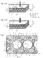
- the wave-shaped profiling 40 is produced by embossing the respective edge region of the gasket layer 2 around the passage opening 3 around. As a result, an increase in thickness compared to the original thickness d of the gasket layer 2 in the region of the undulating profiling 40 is achieved.
- FIGS. 3 (a) and 3 (b) illustrate this increase in thickness on the one hand in the non-installed state of the seal with a preload (force) of 2.4 N / mm 2 acts on the seal substantially perpendicular to the measurement ( FIG. 3 (a) ) as well as in the case of the built-in seal under load with an equivalent force of the screw ( FIG. 3 (b) ).
- a preload (force) of 2.4 N / mm 2 acts on the seal substantially perpendicular to the measurement ( FIG. 3 (a) ) as well as in the case of the built-in seal under load with an equivalent force of the screw ( FIG. 3 (b) ).
- the thickness difference ⁇ VL is derived from the difference of the height h of VL in the region of the wave-shaped profile 40 and the original thickness of the sealing layer d 2.
- the wave-shaped profile 40 according to the invention is designed so that on the one hand, has elastic properties, but also on the other hand, when subjected to a force that corresponds at least to the expected load during operation of the seal, leading to a permanent increase in the combustion chamber edge.
- This permanent elevation is determined by the fact that the cylinder head gasket 1 is first subjected to a force of 2.4 N / mm 2 in the region of the wave-shaped profiling 40.
- This force (marked here with VL) acts on the seal essentially perpendicular to the plane of the gasket layer 2. Substantially perpendicular here means that the force does not deviate more than 2 ° and in particular not more than 1 ° from the vertical.
- the resulting superelevation in the installed state ⁇ b is determined by a force equivalent to the screw force F is applied to the area of the wave-shaped profiling and the corresponding deformation is measured in the vertical direction.
- the so-called characteristic is determined, which indicates the thickness h b of the wave-shaped profiled area as a function of the applied force F.
- the preload VL is usually generated by having a punch from above perpendicular to the area of the undulating profiling is pressed
- the force F is applied to determine the characteristic by means of a flange.
- the elevation ⁇ b at the combustion chamber under installation conditions results from the height difference h b between the wave-shaped profiling under the action of force and the original thickness of the profiled layer, d.
- the sealing element 4 not only ensures elastic sealing of the combustion chamber opening 3, but at the same time also ensures an elevation along the combustion chamber opening 3, which results in the screws passed through the fastening means openings 51, with which the Cylinder head gasket 1 is clamped between the engine block and cylinder head, exert a clamping pressure, which is concentrated substantially in the area around the combustion chamber openings 3.
- the wave-shaped profiles 40 thus combine the functions of an elastic bead and a stopper and ensure by simultaneously existing elastic deformation and lasting supernatant for excellent tightness, which can be further improved by generating a topography in the circumferential direction around the combustion chamber openings 3.
- sealing elements 6 which consist of sealing beads made of elastomer. These sealing beads 6 are formed so high that they protrude beyond the outer surfaces 73 and 73 'of the cover plates 7 and 7'. This is in FIG. 4 to recognize that a cross section along the line CC in FIG. 1 shows.
- the cover plates 7 and 7 ' have recesses 72 which are large enough to accommodate the further passage openings 5 and their sealing elements 6.
- the Elastomerwülste 6 have a width of at least 0.5 mm.
- cover plates 7 and 7 ' serve at the same time as deformation limiter for the sealing elements 6 and prevent the elastomer can be further pressed than up to the height of the cover plates 7 and 7'.
- a common recess 72 in the cover plates 7, 7 ' is present.
- cover plates 7, 7 are also located in the region between adjacent passage openings 3 and the adjacent screw openings 51.
- the elastomeric sealing elements 6 not only surround the passage openings 5 in the hinterland of the seal, but they also extend over in the examples shown the web area between adjacent through holes 3 with their sealing elements. 4
- Another support element is located in the area parallel to the narrow edges of Poetry.
- This support element 10 runs essentially parallel to the edge region of the seal (here only the right sealing element is shown in the region next to the right-hand combustion chamber opening 3).
- the support member 10 is used in a conventional manner to prevent distortion between the engine block and cylinder head in this area.
- the support member 10 is also formed here in the form of a wave-shaped profiling. However, the wave crests and wave troughs are made lower than in the area of the wave-shaped profiles 40 around the combustion chamber openings 3. In addition, there are fewer wave crests and wave troughs.
- the gasket layer 2 which contains the annular profilings 40, is divided into several segments, of which the segment 23 can be seen completely, the segment 24 only partially.
- the segments each include two combustion chamber openings so that multiple segments can be assembled into cylinder head gaskets having four, six or more combustion chamber openings.
- the boundary region in which the segments 23 and 24 adjoin one another is marked with dashed lines and marked with the letter G.
- the cover plates 7 and 7 ' are integrally formed over the entire extent of the cylinder head gasket, so that they also cover the boundary region G.
- the cover plates 7 and 7 ' have no sealing or supporting elements and are completely flat.
- the surface area of the cover plate 7 is in FIG. 1 illustrated by the hatching.
- the second cover plate 7 ' which in FIG. 1 is not visible, is formed according to the cover plate 7.
- FIG. 5 shows a further example of a cylinder head gasket according to the invention in a partial plan view.
- This cylinder head gasket essentially corresponds to that of the FIG. 1 However, it differs in the arrangement of the other through holes 5, so the water and oil holes.
- the cover plates 7 and 7 'do not extend to the outer edge of the gasket layer 2, but leave the outer edge region 25 of the gasket layer 2 free. The reason is that along the outer edge of the gasket layer 2, a sealing bead 8 of elastomeric material rotates.
- FIG. 5 it should include several embodiments of the sealing bead 8 for reasons of simplification.
- the sealing beads 8 have a width of at least 0.5 mm.
- FIG. 6 shows a cross section along the line DD of FIG. 5 in a range from the outer edge of the gasket to a combustion chamber opening 3. Die The combustion chamber opening 3 is again surrounded by a wave-shaped profiling 40.
- FIG. 7 shows a partial cross section along the line EE of FIG. 5 ,
- the sealing of the combustion chamber openings corresponds to that of the preceding figures.
- the outer edge seal is different from the FIG. 6 not sharpened on the outer edge 26 of the gasket layer 2, but applied in the edge region 25 on both sides of the gasket layer 2 as a sealing bead 8 and 8 '.
- FIG. 8 shows a variant of the training of the area in FIG. 6 is shown.
- no outer edge sealing bead is provided, but the cover plates 7 and 7 'reach up to the outer edge of the gasket layer 2 zoom.
- this cross-section corresponds more closely to that of the FIG. 1 as that of the FIG. 5 .
- FIGS. 9 and 10 show Alternatives of the Hinterland support 10.
- the Hinterland support 10 in the embodiment according to FIG. 9 from a surface structuring of the surfaces 21 and 22 of the gasket layer 2.
- This surface structuring which is expediently also produced by embossing, consists for example of checkerboard-like elevations, which are separated by depressions.
- FIG. 10 is used as a hinterland support a strip-shaped pad. It is preferably a metallic support which has been fastened to the gasket layer 2 either by welding or a similar method, or a so-called hard coating, ie a coating of material which is difficult to compress.
- FIG. 11 shows a partial cross section along the outer edge region of in FIG. 5 represented seal, namely along the line HH.
- the cover plates 7 and 7 ' are not brought up to the outer edge of the gasket layer 2, but have a relatively large distance to this.
- the cover plates 7 and 7 'therefore can not act as a press protection for the sealing bead 8.
- the support elements 9 are metal sleeves which have a greater thickness than the thickness of the gasket layer 2 and project over the gasket layer 2 on both sides.
- the metal sleeves 9 are respectively inserted into the screw holes 51 which are adjacent to the outer edge of the gasket layer 2. Due to the greater thickness of the sleeves 9 in comparison to the thickness of the gasket layer 2, these act as anti-compression protection for the Elastomerwülste 8, 8 'at the sealing edge.
- FIGS. 12 to 14 serve the comparison of the flat gasket according to the invention and in particular the sealing of the combustion chamber openings 3 with the usual concepts in the prior art.
- the example according to the invention is in FIG. 13 shown in partial cross-sectional view. The figure essentially corresponds to the right area of FIG. 6 , FIGS. 12 and 14 show the same section, but with different sealing elements for the combustion chamber opening 3.
- the combustion chamber opening 3 is sealed by a plastically deformable multiple bead as a sealing element 4. At this multiple bead is followed by an insert with elastomeric beads 6, 6 ', wherein the insert is welded.
- the thickness of the multiple bead as a sealing element 4 is very large, so that the molded-in multiple bead has predominantly plastic, but only minimal elastic properties.
- the seal according to FIG. 14 on the other hand has a purely elastic bead as a sealing element 4. Without a stopper, however, this elastic bead can be completely flattened in the operation of the seal. A concentration of force at the combustion chamber is not possible without additional measures.
- FIG. 15 shows characteristics for the in FIGS. 12 to 14 illustrated sealing elements. Shown is the deformation of the sealing element against the load.
- the shaded bar illustrates the expected during operation of the seals in a particular engine minimum and maximum loads, so the actual working range of the respective sealing elements during operation of the seal.
- the plastic bead of the FIG. 12 has a higher stiffness, the resilience is low.
- the wave-shaped profiling as a sealing element in the seal according to the invention FIG. 13 both elastic and rigid behavior. It has a high rigidity combined with good springback properties and very consistent and good sealing performance throughout the typical working range.
Claims (28)
- Joint métallique plat (1) avec au moins une couche (2) de joint, qui comprend au moins une ouverture (3) de passage vers une chambre de combustion, qui est entourée d'un élément d'étanchéité élastiquement déformable (4) qui est formé dans la couche (2) de joint selon un profil ondulant (40) d'une manière telle que, sur chacune des surfaces (21, 22) de la couche (2) de joint, au moins deux crêtes (41) d'ondulations et deux creux (42) d'ondulations soient offerts, qui entourent circulairement l'ouverture (3) de passage pour la chambre de combustion, l'épaisseur (hVL) de la couche (2) de joint dans la zone de l'élément d'étanchéité (4) étant, à l'état déchargé, plus importante que l'épaisseur d'origine (d) de la couche (2) de joint, la couche (2) de joint comprenant au moins quatre ouvertures de passage pour des moyens de fixation (51) ainsi qu'au moins une ouverture de passage supplémentaire (5) pour un lubrifiant ou un réfrigérant, qui est entourée par un autre élément d'étanchéité (6) en élastomère, et dans lequel, en dehors du profil ondulant (40), aucun autre élément d'étanchéité ou de support ne sont présents autour de l'ouverture (3) de passage pour la chambre de combustion, caractérisé en ce que l'élément d'étanchéité (4), sous une charge linéaire de 500 à 2800 N/mm dans une direction sensiblement orthogonale au plan (E) de la couche (2) de joint, présente une épaisseur (hb) qui est supérieure de 0,05 à 0,3 mm à l'épaisseur d'origine (d) de la couche (2) de joint, l'ouverture (3) de passage pour la chambre de combustion ayant un diamètre inférieur à 200 mm et la couche (2) de joint étant constituée d'un métal avec une résistance à la traction d'au moins 600 N/mm2.
- Joint métallique plat selon la revendication 1, caractérisé en ce que le profil ondulant (40) a, en section transversale, un profil sinusoïdal, trapézoïdal ou en zigzag.
- Joint métallique plat selon la revendication 1 ou 2, caractérisé en ce que le profil ondulant (40), dans la direction radiale et/ou circonférentielle autour de l'ouverture (3) de passage pour la chambre de combustion, est conformé modifiable, en particulier en ce qui concerne au moins l'une des propriétés suivantes :- hauteur des crêtes (41) d'ondulations- forme en section transversale des crêtes (41) d'ondulations et/ou des creux (42) d'ondulations,- distance entre deux crêtes (41) d'ondulations adjacentes et- épaisseur du matériau dans la zone des crêtes (41) d'ondulations et/ou des creux (42) d'ondulations.
- Joint métallique plat selon l'une des revendications précédentes, caractérisé en ce que la distance (a) entre les apex (43) de crêtes d'ondulations adjacentes (41) est de jusqu'à 2,0 mm, de manière préférable jusqu'à 1,7 mm, de manière particulièrement préférable jusqu'à 1,5 mm et en particulier jusqu'à 1,0 mm.
- Joint métallique plat selon l'une des revendications précédentes, caractérisé en ce que la couche (2) de joint possède une épaisseur (d) de 0,3 à 0,6 mm, en particulier de 0,3 à 0,5 mm.
- Joint métallique plat selon l'une des revendications précédentes, caractérisé en ce que 'il comprend plusieurs ouvertures (3) de passage pour la chambre de combustion qui sont chacune séparées par une bande d'une largeur d'au moins 4 mm.
- Joint métallique plat selon l'une des revendications précédentes, caractérisé en ce que la couche (2) de joint est constituée d'un métal avec une résistance à la traction d'au moins 1000 N/mm2 et est en particulier constitué d'acier au carbone, d'acier inoxydable ou d'un acier à ressorts.
- Joint métallique plat selon l'une des revendications précédentes, caractérisé en ce que la couche (2) de joint comprend plusieurs ouvertures (3) de passage pour la chambre de combustion entourées d'un profil ondulant (40) et est divisée en au moins deux segments (23, 24) qui, dans la zone entre deux ouvertures (3) de passage pour la chambre de combustion, sont contigus avec des profils ondulants (40).
- Joint métallique plat selon l'une des revendications précédentes, caractérisé en ce que l'élément d'étanchéité (4) sous une charge avec une compression linéaire de 800 à 2500 N/mm et en particulier de 800 à 1500 N/mm dans une direction essentiellement orthogonale au plan (E) de la couche (2) de joint présente une épaisseur (hb) qui est supérieure de 0,05 à 0,3 mm à l'épaisseur d'origine (d) de la couche (2) de joint.
- Joint métallique plat selon l'une des revendications précédentes, caractérisé en ce que le joint ne comprend aucune autre couche de joint en complément à la couche (2) de joint.
- Joint métallique plat selon l'une des revendications 1 à 9, caractérisé en ce qu'il comprend au moins une feuille métallique de couverture (7, 7'), qui s'aboute contre l'une des surfaces (21, 22) de la couche (2) de joint et recouvre de cette manière la zone du profil ondulant (40).
- Joint métallique plat selon la revendication 11, caractérisé en ce que ladite au moins une feuille métallique de couverture (7, 7') dans la zone opposée au profil ondulant (40) comprend une section plane (71, 71').
- Joint métallique plat selon la revendication 11 ou 12, caractérisé en ce qu' un cordon circulaire est formé dans ladite au moins une feuille métallique de couverture (7, 7') en tant qu'élément d'étanchéité pour ladite au moins une ouverture de passage supplémentaire (5) de la couche (2) de joint.
- Joint métallique plat selon la revendication 11 ou 12, caractérisé en ce que ladite au moins une feuille métallique de couverture (7, 7') dans la zone située autour de ladite au moins une ouverture supplémentaire (5) de passage de la couche de joint selon la revendication 8 comprend un renfoncement (72) de façon que l'élément d'étanchéité (6) en élastomère entourant l'ouverture de passage supplémentaire (5) soit engagé dans le renfoncement (72).
- Joint métallique plat selon la revendication 14, caractérisé en ce que l'élément d'étanchéité (6) en élastomère soit formé avec une hauteur telle qu'il fasse saillie de la surface (73, 73') de ladite au moins une feuille métallique de couverture (7, 7') en pointant hors de la couche (2) de joint.
- Joint métallique plat selon l'une des revendications 11 à 15, caractérisé en ce que ladite au moins une feuille métallique de couverture (7, 7') couvre la zone dans laquelle des segments adjacents (23, 24) de la couche (2) de joint sont contigus selon la revendication 7.
- Joint métallique plat selon l'une des revendications 11 à 16, caractérisé en ce que ladite au moins une feuille métallique de couverture (7, 7') est encastrée dans la zone du bord extérieur (25) de la couche (2) de joint au moins pour certaines sections, et particulièrement de manière complète.
- Joint métallique plat selon l'une des revendications précédentes, caractérisé en ce qu'une lèvre d'étanchéité (8, 8') en élastomère faisant saillie des deux surfaces (21, 22) de la couche (2) de joint s'étend le long du bord extérieur (25) de la couche (2) de joint au moins sur certaines sections.
- Joint métallique plat selon l'une des revendications précédentes, caractérisé en ce que l'élément d'étanchéité (6) en élastomère et/ou la lèvre d'étanchéité (8, 8') est constituée d'un élastomère d'une dureté shore A d'au moins 35.
- Joint métallique plat selon l'une des revendications précédentes, caractérisé en ce que l'élément d'étanchéité (6) en élastomère et/ou la lèvre d'étanchéité (8, 8') présente(nt) une largeur d'au moins 0,5 mm.
- Joint métallique plat selon l'une des revendications 18 à 20, caractérisé en ce que la lèvre d'étanchéité est disposée de telle sorte qu'elle fasse saillie au-delà du bord extérieur (26) de la couche (2) de joint.
- Joint métallique plat selon l'une des revendications 17 à 21, caractérisé en ce qu' il comprend au moins un élément de support.
- Joint métallique plat selon la revendication 22, caractérisé en ce que la couche (2) de joint adjacente à la lèvre d'étanchéité (8, 8') comprend au moins un élément de support local, qui fait saillie au-delà d'au moins une surface (21, 22) de la couche (2) de joint avec une hauteur qui est inférieure la saillie de la lèvre d'étanchéité (8, 8') au-delà de cette surface (21, 22).
- Joint métallique plat selon la revendication 23, caractérisé en ce que l'élément de support (9) est inséré comme un manchon dans une autre ouverture (5) de passage, en particulier dans une ouverture (51) pour une vis.
- Joint métallique plat selon l'une des revendications 14 à 24, caractérisé en ce qu'il comprend plusieurs ouvertures (3) de passage entourées par des profils ondulants (40) et en ce qu'un élément d'étanchéité en élastomère (6) s'étend à travers la zone entre des ouvertures de passage adjacentes (3).
- Joint métallique plat selon l'une des revendications précédentes, à savoir joint de tête de cylindre avec un prolongement dans sa direction longitudinale pouvant atteindre jusqu'à 1500 mm et dans sa direction transversale jusqu'à 500 mm.
- Utilisation d'un joint métallique plat selon l'une des revendications 1 à 26, destiné à assurer l'étanchéité entre une tête de cylindre et un bloc moteur dans un moteur sans aucune chemise, ou avec des chemises avec une saillie pour les chemises, ou un renfoncement pour les chemises de 0,15 mm tout au plus.
- Utilisation d'un joint métallique plat selon l'une des revendications 1 à 26, destiné à assurer l'étanchéité entre une tête de cylindre et un bloc moteur dans un moteur avec une pression d'allumage d'au moins 140 bar, de manière préférée d'au moins 160 bar, et de manière particulièrement préférée d'au moins 180 bar.
Priority Applications (7)
| Application Number | Priority Date | Filing Date | Title |
|---|---|---|---|
| EP07010816.2A EP1998086B1 (fr) | 2007-05-31 | 2007-05-31 | Joint plat métallique |
| CA002682705A CA2682705A1 (fr) | 2007-04-24 | 2008-04-24 | Joint plat metallique |
| US12/451,026 US8496253B2 (en) | 2007-04-24 | 2008-04-24 | Metallic flat gasket |
| BRPI0810669-0A BRPI0810669B1 (pt) | 2007-04-24 | 2008-04-24 | junta metálica plana |
| PCT/EP2008/003327 WO2008128785A1 (fr) | 2007-04-24 | 2008-04-24 | Joint plat métallique |
| JP2010504548A JP2010525270A (ja) | 2007-04-24 | 2008-04-24 | 金属製平形ガスケット |
| MX2009011465A MX2009011465A (es) | 2007-04-24 | 2008-04-24 | Junta metalica plana. |
Applications Claiming Priority (1)
| Application Number | Priority Date | Filing Date | Title |
|---|---|---|---|
| EP07010816.2A EP1998086B1 (fr) | 2007-05-31 | 2007-05-31 | Joint plat métallique |
Publications (2)
| Publication Number | Publication Date |
|---|---|
| EP1998086A1 EP1998086A1 (fr) | 2008-12-03 |
| EP1998086B1 true EP1998086B1 (fr) | 2014-07-30 |
Family
ID=38650829
Family Applications (1)
| Application Number | Title | Priority Date | Filing Date |
|---|---|---|---|
| EP07010816.2A Active EP1998086B1 (fr) | 2007-04-24 | 2007-05-31 | Joint plat métallique |
Country Status (1)
| Country | Link |
|---|---|
| EP (1) | EP1998086B1 (fr) |
Families Citing this family (3)
| Publication number | Priority date | Publication date | Assignee | Title |
|---|---|---|---|---|
| DE202008014927U1 (de) | 2008-11-11 | 2009-01-15 | Reinz-Dichtungs-Gmbh | Metallische Dichtung für Hochtemperaturanwendungen |
| DE102010039681B4 (de) * | 2010-08-24 | 2014-07-10 | Federal-Mogul Sealing Systems Gmbh | Verfahren zur Herstellung eines Flachbauteiles mit mindestens einem Funktionselement und mit dem Verfahren hergestelltes Flachbauteil |
| DE102018106362A1 (de) | 2018-03-19 | 2019-09-19 | Technische Universität Hamburg | Vorrichtungen und verfahren zum bearbeiten metallischer objekte |
Family Cites Families (4)
| Publication number | Priority date | Publication date | Assignee | Title |
|---|---|---|---|---|
| FR2672938B1 (fr) * | 1991-02-14 | 1993-05-28 | Curty Soc | Joint de culasse pour moteur a combustion interne equipe d'un joint de culasse par chambre de combustion. |
| US5890719A (en) * | 1996-08-27 | 1999-04-06 | Parker-Hannifin Corporation | Combination metal and elastomer cylinder head gasket |
| DE10060872B4 (de) * | 2000-06-15 | 2012-11-15 | Reinz-Dichtungs-Gmbh | Flachdichtung |
| ATE359462T1 (de) * | 2004-12-21 | 2007-05-15 | Reinz Dichtungs Gmbh | Metallische flachdichtung |
-
2007
- 2007-05-31 EP EP07010816.2A patent/EP1998086B1/fr active Active
Also Published As
| Publication number | Publication date |
|---|---|
| EP1998086A1 (fr) | 2008-12-03 |
Similar Documents
| Publication | Publication Date | Title |
|---|---|---|
| EP1577589B1 (fr) | Joint de culasse | |
| DE19829656B4 (de) | Metalldichtung | |
| DE4142600C2 (de) | Zylinderkopfdichtung | |
| EP1985898A1 (fr) | Joint plat métallique | |
| EP1298365B1 (fr) | Joint de culasse métallique | |
| DE20121984U1 (de) | Flachdichtung | |
| EP1600671A1 (fr) | Joint de culasse | |
| EP1482218B1 (fr) | Joint de culasse | |
| EP1679457B1 (fr) | Joint plat | |
| EP1774207A1 (fr) | Joint de culasse | |
| EP1875110B1 (fr) | Joint plat, notamment joint de culasse | |
| EP1998086B1 (fr) | Joint plat métallique | |
| EP2072818A1 (fr) | Joint plat métallique et son utilisation | |
| DE102006021625B4 (de) | Abdeckungsvorrichtung mit Dichtungselement für Verbrennungskraftmaschinen | |
| EP2396574B1 (fr) | Joint plat comportant un limitateur de deformation ondule | |
| DE19808373A1 (de) | Flachdichtung | |
| DE102016002582A1 (de) | Flachdichtung, insbesondere Zylinderkopfdichtung | |
| EP0939256B1 (fr) | Système d'étanchéité | |
| EP1992847A1 (fr) | Joint plat métallique | |
| WO2019038319A1 (fr) | Joint de culasse | |
| EP0893630A2 (fr) | Joint plat métallique | |
| EP3099962A1 (fr) | Joint de culasse et système d'étanchéité comprenant ledit joint de culasse | |
| WO2018024689A1 (fr) | Joint plat et moteur à combustion interne doté d'un tel joint plat | |
| DE19549595C2 (de) | Zylinderkopfdichtung | |
| DE102020211185A1 (de) | Zylinderkopfdichtung mit einer Trägerlage und zumindest einem Einsatzdichtelement |
Legal Events
| Date | Code | Title | Description |
|---|---|---|---|
| PUAI | Public reference made under article 153(3) epc to a published international application that has entered the european phase |
Free format text: ORIGINAL CODE: 0009012 |
|
| AK | Designated contracting states |
Kind code of ref document: A1 Designated state(s): AT BE BG CH CY CZ DE DK EE ES FI FR GB GR HU IE IS IT LI LT LU LV MC MT NL PL PT RO SE SI SK TR |
|
| AX | Request for extension of the european patent |
Extension state: AL BA HR MK RS |
|
| 17P | Request for examination filed |
Effective date: 20090513 |
|
| AKX | Designation fees paid |
Designated state(s): AT BE BG CH CY CZ DE DK EE ES FI FR GB GR HU IE IS IT LI LT LU LV MC MT NL PL PT RO SE SI SK TR |
|
| 17Q | First examination report despatched |
Effective date: 20120620 |
|
| GRAP | Despatch of communication of intention to grant a patent |
Free format text: ORIGINAL CODE: EPIDOSNIGR1 |
|
| INTG | Intention to grant announced |
Effective date: 20140414 |
|
| GRAS | Grant fee paid |
Free format text: ORIGINAL CODE: EPIDOSNIGR3 |
|
| GRAA | (expected) grant |
Free format text: ORIGINAL CODE: 0009210 |
|
| AK | Designated contracting states |
Kind code of ref document: B1 Designated state(s): AT BE BG CH CY CZ DE DK EE ES FI FR GB GR HU IE IS IT LI LT LU LV MC MT NL PL PT RO SE SI SK TR |
|
| REG | Reference to a national code |
Ref country code: GB Ref legal event code: FG4D Free format text: NOT ENGLISH |
|
| REG | Reference to a national code |
Ref country code: CH Ref legal event code: EP |
|
| REG | Reference to a national code |
Ref country code: AT Ref legal event code: REF Ref document number: 680148 Country of ref document: AT Kind code of ref document: T Effective date: 20140815 |
|
| REG | Reference to a national code |
Ref country code: IE Ref legal event code: FG4D Free format text: LANGUAGE OF EP DOCUMENT: GERMAN |
|
| REG | Reference to a national code |
Ref country code: DE Ref legal event code: R096 Ref document number: 502007013322 Country of ref document: DE Effective date: 20140911 |
|
| REG | Reference to a national code |
Ref country code: NL Ref legal event code: VDEP Effective date: 20140730 |
|
| REG | Reference to a national code |
Ref country code: LT Ref legal event code: MG4D |
|
| PG25 | Lapsed in a contracting state [announced via postgrant information from national office to epo] |
Ref country code: GR Free format text: LAPSE BECAUSE OF FAILURE TO SUBMIT A TRANSLATION OF THE DESCRIPTION OR TO PAY THE FEE WITHIN THE PRESCRIBED TIME-LIMIT Effective date: 20141031 Ref country code: LT Free format text: LAPSE BECAUSE OF FAILURE TO SUBMIT A TRANSLATION OF THE DESCRIPTION OR TO PAY THE FEE WITHIN THE PRESCRIBED TIME-LIMIT Effective date: 20140730 Ref country code: FI Free format text: LAPSE BECAUSE OF FAILURE TO SUBMIT A TRANSLATION OF THE DESCRIPTION OR TO PAY THE FEE WITHIN THE PRESCRIBED TIME-LIMIT Effective date: 20140730 Ref country code: SE Free format text: LAPSE BECAUSE OF FAILURE TO SUBMIT A TRANSLATION OF THE DESCRIPTION OR TO PAY THE FEE WITHIN THE PRESCRIBED TIME-LIMIT Effective date: 20140730 Ref country code: BG Free format text: LAPSE BECAUSE OF FAILURE TO SUBMIT A TRANSLATION OF THE DESCRIPTION OR TO PAY THE FEE WITHIN THE PRESCRIBED TIME-LIMIT Effective date: 20141030 Ref country code: ES Free format text: LAPSE BECAUSE OF FAILURE TO SUBMIT A TRANSLATION OF THE DESCRIPTION OR TO PAY THE FEE WITHIN THE PRESCRIBED TIME-LIMIT Effective date: 20140730 Ref country code: PT Free format text: LAPSE BECAUSE OF FAILURE TO SUBMIT A TRANSLATION OF THE DESCRIPTION OR TO PAY THE FEE WITHIN THE PRESCRIBED TIME-LIMIT Effective date: 20141202 |
|
| PG25 | Lapsed in a contracting state [announced via postgrant information from national office to epo] |
Ref country code: PL Free format text: LAPSE BECAUSE OF FAILURE TO SUBMIT A TRANSLATION OF THE DESCRIPTION OR TO PAY THE FEE WITHIN THE PRESCRIBED TIME-LIMIT Effective date: 20140730 Ref country code: LV Free format text: LAPSE BECAUSE OF FAILURE TO SUBMIT A TRANSLATION OF THE DESCRIPTION OR TO PAY THE FEE WITHIN THE PRESCRIBED TIME-LIMIT Effective date: 20140730 Ref country code: CY Free format text: LAPSE BECAUSE OF FAILURE TO SUBMIT A TRANSLATION OF THE DESCRIPTION OR TO PAY THE FEE WITHIN THE PRESCRIBED TIME-LIMIT Effective date: 20140730 Ref country code: NL Free format text: LAPSE BECAUSE OF FAILURE TO SUBMIT A TRANSLATION OF THE DESCRIPTION OR TO PAY THE FEE WITHIN THE PRESCRIBED TIME-LIMIT Effective date: 20140730 Ref country code: IS Free format text: LAPSE BECAUSE OF FAILURE TO SUBMIT A TRANSLATION OF THE DESCRIPTION OR TO PAY THE FEE WITHIN THE PRESCRIBED TIME-LIMIT Effective date: 20141130 |
|
| PG25 | Lapsed in a contracting state [announced via postgrant information from national office to epo] |
Ref country code: EE Free format text: LAPSE BECAUSE OF FAILURE TO SUBMIT A TRANSLATION OF THE DESCRIPTION OR TO PAY THE FEE WITHIN THE PRESCRIBED TIME-LIMIT Effective date: 20140730 Ref country code: DK Free format text: LAPSE BECAUSE OF FAILURE TO SUBMIT A TRANSLATION OF THE DESCRIPTION OR TO PAY THE FEE WITHIN THE PRESCRIBED TIME-LIMIT Effective date: 20140730 Ref country code: SK Free format text: LAPSE BECAUSE OF FAILURE TO SUBMIT A TRANSLATION OF THE DESCRIPTION OR TO PAY THE FEE WITHIN THE PRESCRIBED TIME-LIMIT Effective date: 20140730 Ref country code: CZ Free format text: LAPSE BECAUSE OF FAILURE TO SUBMIT A TRANSLATION OF THE DESCRIPTION OR TO PAY THE FEE WITHIN THE PRESCRIBED TIME-LIMIT Effective date: 20140730 Ref country code: RO Free format text: LAPSE BECAUSE OF FAILURE TO SUBMIT A TRANSLATION OF THE DESCRIPTION OR TO PAY THE FEE WITHIN THE PRESCRIBED TIME-LIMIT Effective date: 20140730 Ref country code: IT Free format text: LAPSE BECAUSE OF FAILURE TO SUBMIT A TRANSLATION OF THE DESCRIPTION OR TO PAY THE FEE WITHIN THE PRESCRIBED TIME-LIMIT Effective date: 20140730 |
|
| REG | Reference to a national code |
Ref country code: DE Ref legal event code: R097 Ref document number: 502007013322 Country of ref document: DE |
|
| PLBE | No opposition filed within time limit |
Free format text: ORIGINAL CODE: 0009261 |
|
| STAA | Information on the status of an ep patent application or granted ep patent |
Free format text: STATUS: NO OPPOSITION FILED WITHIN TIME LIMIT |
|
| 26N | No opposition filed |
Effective date: 20150504 |
|
| PG25 | Lapsed in a contracting state [announced via postgrant information from national office to epo] |
Ref country code: SI Free format text: LAPSE BECAUSE OF FAILURE TO SUBMIT A TRANSLATION OF THE DESCRIPTION OR TO PAY THE FEE WITHIN THE PRESCRIBED TIME-LIMIT Effective date: 20140730 |
|
| REG | Reference to a national code |
Ref country code: CH Ref legal event code: PL |
|
| GBPC | Gb: european patent ceased through non-payment of renewal fee |
Effective date: 20150531 |
|
| PG25 | Lapsed in a contracting state [announced via postgrant information from national office to epo] |
Ref country code: LI Free format text: LAPSE BECAUSE OF NON-PAYMENT OF DUE FEES Effective date: 20150531 Ref country code: CH Free format text: LAPSE BECAUSE OF NON-PAYMENT OF DUE FEES Effective date: 20150531 Ref country code: MC Free format text: LAPSE BECAUSE OF FAILURE TO SUBMIT A TRANSLATION OF THE DESCRIPTION OR TO PAY THE FEE WITHIN THE PRESCRIBED TIME-LIMIT Effective date: 20140730 Ref country code: LU Free format text: LAPSE BECAUSE OF FAILURE TO SUBMIT A TRANSLATION OF THE DESCRIPTION OR TO PAY THE FEE WITHIN THE PRESCRIBED TIME-LIMIT Effective date: 20150531 |
|
| REG | Reference to a national code |
Ref country code: IE Ref legal event code: MM4A |
|
| REG | Reference to a national code |
Ref country code: FR Ref legal event code: ST Effective date: 20160129 |
|
| PG25 | Lapsed in a contracting state [announced via postgrant information from national office to epo] |
Ref country code: IE Free format text: LAPSE BECAUSE OF NON-PAYMENT OF DUE FEES Effective date: 20150531 Ref country code: GB Free format text: LAPSE BECAUSE OF NON-PAYMENT OF DUE FEES Effective date: 20150531 |
|
| PG25 | Lapsed in a contracting state [announced via postgrant information from national office to epo] |
Ref country code: FR Free format text: LAPSE BECAUSE OF NON-PAYMENT OF DUE FEES Effective date: 20150601 |
|
| REG | Reference to a national code |
Ref country code: AT Ref legal event code: MM01 Ref document number: 680148 Country of ref document: AT Kind code of ref document: T Effective date: 20150531 |
|
| PG25 | Lapsed in a contracting state [announced via postgrant information from national office to epo] |
Ref country code: AT Free format text: LAPSE BECAUSE OF NON-PAYMENT OF DUE FEES Effective date: 20150531 |
|
| PG25 | Lapsed in a contracting state [announced via postgrant information from national office to epo] |
Ref country code: MT Free format text: LAPSE BECAUSE OF FAILURE TO SUBMIT A TRANSLATION OF THE DESCRIPTION OR TO PAY THE FEE WITHIN THE PRESCRIBED TIME-LIMIT Effective date: 20140730 |
|
| PG25 | Lapsed in a contracting state [announced via postgrant information from national office to epo] |
Ref country code: HU Free format text: LAPSE BECAUSE OF FAILURE TO SUBMIT A TRANSLATION OF THE DESCRIPTION OR TO PAY THE FEE WITHIN THE PRESCRIBED TIME-LIMIT; INVALID AB INITIO Effective date: 20070531 |
|
| PG25 | Lapsed in a contracting state [announced via postgrant information from national office to epo] |
Ref country code: BE Free format text: LAPSE BECAUSE OF NON-PAYMENT OF DUE FEES Effective date: 20150531 |
|
| PG25 | Lapsed in a contracting state [announced via postgrant information from national office to epo] |
Ref country code: TR Free format text: LAPSE BECAUSE OF FAILURE TO SUBMIT A TRANSLATION OF THE DESCRIPTION OR TO PAY THE FEE WITHIN THE PRESCRIBED TIME-LIMIT Effective date: 20140730 |
|
| REG | Reference to a national code |
Ref country code: DE Ref legal event code: R084 Ref document number: 502007013322 Country of ref document: DE |
|
| P01 | Opt-out of the competence of the unified patent court (upc) registered |
Effective date: 20230522 |
|
| PGFP | Annual fee paid to national office [announced via postgrant information from national office to epo] |
Ref country code: DE Payment date: 20230419 Year of fee payment: 17 |