EP1998086B1 - Metal flat gasket - Google Patents
Metal flat gasket Download PDFInfo
- Publication number
- EP1998086B1 EP1998086B1 EP07010816.2A EP07010816A EP1998086B1 EP 1998086 B1 EP1998086 B1 EP 1998086B1 EP 07010816 A EP07010816 A EP 07010816A EP 1998086 B1 EP1998086 B1 EP 1998086B1
- Authority
- EP
- European Patent Office
- Prior art keywords
- gasket
- gasket layer
- metallic flat
- layer
- sealing
- Prior art date
- Legal status (The legal status is an assumption and is not a legal conclusion. Google has not performed a legal analysis and makes no representation as to the accuracy of the status listed.)
- Active
Links
- 239000002184 metal Substances 0.000 title claims description 15
- 238000007789 sealing Methods 0.000 claims description 136
- 238000002485 combustion reaction Methods 0.000 claims description 71
- 239000011324 bead Substances 0.000 claims description 55
- 229920001971 elastomer Polymers 0.000 claims description 22
- 239000000806 elastomer Substances 0.000 claims description 21
- 239000000463 material Substances 0.000 claims description 14
- 238000007906 compression Methods 0.000 claims description 6
- 230000006835 compression Effects 0.000 claims description 4
- 239000002826 coolant Substances 0.000 claims description 4
- 229910000975 Carbon steel Inorganic materials 0.000 claims description 3
- 229910000639 Spring steel Inorganic materials 0.000 claims description 3
- 239000000314 lubricant Substances 0.000 claims description 3
- 229910001220 stainless steel Inorganic materials 0.000 claims description 2
- 239000010962 carbon steel Substances 0.000 claims 1
- 239000010935 stainless steel Substances 0.000 claims 1
- 239000010410 layer Substances 0.000 description 115
- 238000013461 design Methods 0.000 description 6
- 239000004033 plastic Substances 0.000 description 6
- 229920003023 plastic Polymers 0.000 description 6
- 238000012876 topography Methods 0.000 description 6
- 238000000576 coating method Methods 0.000 description 5
- 238000003466 welding Methods 0.000 description 5
- 229910000831 Steel Inorganic materials 0.000 description 4
- 230000015572 biosynthetic process Effects 0.000 description 4
- 239000011248 coating agent Substances 0.000 description 4
- 238000010276 construction Methods 0.000 description 4
- 238000004519 manufacturing process Methods 0.000 description 4
- 239000010959 steel Substances 0.000 description 4
- 239000000498 cooling water Substances 0.000 description 3
- 238000004049 embossing Methods 0.000 description 3
- 238000005259 measurement Methods 0.000 description 3
- 239000000243 solution Substances 0.000 description 3
- 239000006228 supernatant Substances 0.000 description 3
- KUDUQBURMYMBIJ-UHFFFAOYSA-N 2-prop-2-enoyloxyethyl prop-2-enoate Chemical compound C=CC(=O)OCCOC(=O)C=C KUDUQBURMYMBIJ-UHFFFAOYSA-N 0.000 description 2
- 239000005062 Polybutadiene Substances 0.000 description 2
- NIXOWILDQLNWCW-UHFFFAOYSA-N acrylic acid group Chemical group C(C=C)(=O)O NIXOWILDQLNWCW-UHFFFAOYSA-N 0.000 description 2
- 238000004026 adhesive bonding Methods 0.000 description 2
- 230000008859 change Effects 0.000 description 2
- 239000012141 concentrate Substances 0.000 description 2
- 238000003780 insertion Methods 0.000 description 2
- 230000037431 insertion Effects 0.000 description 2
- 230000001788 irregular Effects 0.000 description 2
- 238000000034 method Methods 0.000 description 2
- 229920002857 polybutadiene Polymers 0.000 description 2
- 239000004814 polyurethane Substances 0.000 description 2
- 230000036316 preload Effects 0.000 description 2
- 230000000630 rising effect Effects 0.000 description 2
- 238000000926 separation method Methods 0.000 description 2
- 229920002725 thermoplastic elastomer Polymers 0.000 description 2
- 230000008719 thickening Effects 0.000 description 2
- 229920002943 EPDM rubber Polymers 0.000 description 1
- 229920000181 Ethylene propylene rubber Polymers 0.000 description 1
- 230000009471 action Effects 0.000 description 1
- 230000006978 adaptation Effects 0.000 description 1
- 238000013459 approach Methods 0.000 description 1
- 238000010420 art technique Methods 0.000 description 1
- 238000005452 bending Methods 0.000 description 1
- 230000008901 benefit Effects 0.000 description 1
- 238000007796 conventional method Methods 0.000 description 1
- 229920001577 copolymer Polymers 0.000 description 1
- 230000005489 elastic deformation Effects 0.000 description 1
- 239000013536 elastomeric material Substances 0.000 description 1
- 230000001747 exhibiting effect Effects 0.000 description 1
- 239000000945 filler Substances 0.000 description 1
- 229920002313 fluoropolymer Polymers 0.000 description 1
- 239000004811 fluoropolymer Substances 0.000 description 1
- 239000002737 fuel gas Substances 0.000 description 1
- 230000012447 hatching Effects 0.000 description 1
- 238000002347 injection Methods 0.000 description 1
- 239000007924 injection Substances 0.000 description 1
- 238000009434 installation Methods 0.000 description 1
- 238000005304 joining Methods 0.000 description 1
- 230000002045 lasting effect Effects 0.000 description 1
- 230000013011 mating Effects 0.000 description 1
- 238000000465 moulding Methods 0.000 description 1
- 229920003052 natural elastomer Polymers 0.000 description 1
- 229920001194 natural rubber Polymers 0.000 description 1
- 230000002085 persistent effect Effects 0.000 description 1
- 229920000058 polyacrylate Polymers 0.000 description 1
- 229920002635 polyurethane Polymers 0.000 description 1
- 238000002360 preparation method Methods 0.000 description 1
- 238000004080 punching Methods 0.000 description 1
- 230000009467 reduction Effects 0.000 description 1
- 230000003716 rejuvenation Effects 0.000 description 1
- 239000005060 rubber Substances 0.000 description 1
- 238000007493 shaping process Methods 0.000 description 1
- 229920002379 silicone rubber Polymers 0.000 description 1
- 239000004945 silicone rubber Substances 0.000 description 1
- 238000004088 simulation Methods 0.000 description 1
- 239000002356 single layer Substances 0.000 description 1
- 125000006850 spacer group Chemical group 0.000 description 1
- 239000007858 starting material Substances 0.000 description 1
- 229920003051 synthetic elastomer Polymers 0.000 description 1
- 238000012549 training Methods 0.000 description 1
- XLYOFNOQVPJJNP-UHFFFAOYSA-N water Substances O XLYOFNOQVPJJNP-UHFFFAOYSA-N 0.000 description 1
Images


Classifications
-
- F—MECHANICAL ENGINEERING; LIGHTING; HEATING; WEAPONS; BLASTING
- F16—ENGINEERING ELEMENTS AND UNITS; GENERAL MEASURES FOR PRODUCING AND MAINTAINING EFFECTIVE FUNCTIONING OF MACHINES OR INSTALLATIONS; THERMAL INSULATION IN GENERAL
- F16J—PISTONS; CYLINDERS; SEALINGS
- F16J15/00—Sealings
- F16J15/02—Sealings between relatively-stationary surfaces
- F16J15/06—Sealings between relatively-stationary surfaces with solid packing compressed between sealing surfaces
- F16J15/08—Sealings between relatively-stationary surfaces with solid packing compressed between sealing surfaces with exclusively metal packing
- F16J15/0818—Flat gaskets
-
- F—MECHANICAL ENGINEERING; LIGHTING; HEATING; WEAPONS; BLASTING
- F02—COMBUSTION ENGINES; HOT-GAS OR COMBUSTION-PRODUCT ENGINE PLANTS
- F02F—CYLINDERS, PISTONS OR CASINGS, FOR COMBUSTION ENGINES; ARRANGEMENTS OF SEALINGS IN COMBUSTION ENGINES
- F02F11/00—Arrangements of sealings in combustion engines
- F02F11/002—Arrangements of sealings in combustion engines involving cylinder heads
-
- F—MECHANICAL ENGINEERING; LIGHTING; HEATING; WEAPONS; BLASTING
- F16—ENGINEERING ELEMENTS AND UNITS; GENERAL MEASURES FOR PRODUCING AND MAINTAINING EFFECTIVE FUNCTIONING OF MACHINES OR INSTALLATIONS; THERMAL INSULATION IN GENERAL
- F16J—PISTONS; CYLINDERS; SEALINGS
- F16J15/00—Sealings
- F16J15/02—Sealings between relatively-stationary surfaces
- F16J15/06—Sealings between relatively-stationary surfaces with solid packing compressed between sealing surfaces
- F16J15/08—Sealings between relatively-stationary surfaces with solid packing compressed between sealing surfaces with exclusively metal packing
- F16J15/0818—Flat gaskets
- F16J15/0825—Flat gaskets laminated
-
- F—MECHANICAL ENGINEERING; LIGHTING; HEATING; WEAPONS; BLASTING
- F16—ENGINEERING ELEMENTS AND UNITS; GENERAL MEASURES FOR PRODUCING AND MAINTAINING EFFECTIVE FUNCTIONING OF MACHINES OR INSTALLATIONS; THERMAL INSULATION IN GENERAL
- F16J—PISTONS; CYLINDERS; SEALINGS
- F16J15/00—Sealings
- F16J15/02—Sealings between relatively-stationary surfaces
- F16J15/06—Sealings between relatively-stationary surfaces with solid packing compressed between sealing surfaces
- F16J15/08—Sealings between relatively-stationary surfaces with solid packing compressed between sealing surfaces with exclusively metal packing
- F16J15/0818—Flat gaskets
- F16J2015/085—Flat gaskets without fold over
-
- F—MECHANICAL ENGINEERING; LIGHTING; HEATING; WEAPONS; BLASTING
- F16—ENGINEERING ELEMENTS AND UNITS; GENERAL MEASURES FOR PRODUCING AND MAINTAINING EFFECTIVE FUNCTIONING OF MACHINES OR INSTALLATIONS; THERMAL INSULATION IN GENERAL
- F16J—PISTONS; CYLINDERS; SEALINGS
- F16J15/00—Sealings
- F16J15/02—Sealings between relatively-stationary surfaces
- F16J15/06—Sealings between relatively-stationary surfaces with solid packing compressed between sealing surfaces
- F16J15/08—Sealings between relatively-stationary surfaces with solid packing compressed between sealing surfaces with exclusively metal packing
- F16J15/0818—Flat gaskets
- F16J2015/0856—Flat gaskets with a non-metallic coating or strip
-
- F—MECHANICAL ENGINEERING; LIGHTING; HEATING; WEAPONS; BLASTING
- F16—ENGINEERING ELEMENTS AND UNITS; GENERAL MEASURES FOR PRODUCING AND MAINTAINING EFFECTIVE FUNCTIONING OF MACHINES OR INSTALLATIONS; THERMAL INSULATION IN GENERAL
- F16J—PISTONS; CYLINDERS; SEALINGS
- F16J15/00—Sealings
- F16J15/02—Sealings between relatively-stationary surfaces
- F16J15/06—Sealings between relatively-stationary surfaces with solid packing compressed between sealing surfaces
- F16J15/08—Sealings between relatively-stationary surfaces with solid packing compressed between sealing surfaces with exclusively metal packing
- F16J15/0818—Flat gaskets
- F16J2015/0862—Flat gaskets with a bore ring
Definitions
- the invention relates to a metallic flat gasket, which is particularly suitable as a cylinder head gasket for commercial vehicles.
- cylinder head gaskets the sealing of the combustion chamber openings, in the case of exhaust manifold gaskets of the fuel gas openings, is of particular importance.
- it is therefore necessary, especially in applications that are commonly found in truck diesel engines with or without liners, to concentrate the bolt force with which the cylinder head and engine block are connected to one another at the combustion chamber.
- it is customary in the case of cylinder head gaskets for internal combustion engines with little or no bushing projection to produce a so-called superelevation at the combustion chamber edge.
- the total thickness of the gasket layers of the cylinder head gasket is greater than the total thickness of the gasket layers in regions of the gasket which are further away from the combustion chamber openings, the so-called hinterland.
- stoppers are usually massive annular inserts that run along the edge of the combustion chamber.
- the height of the stoppers is generally dimensioned such that, if appropriate in combination with the thickness of the sealing layers present in the area around the combustion chamber opening, they completely fill the sealing gap between the engine block and cylinder head in the area around the combustion chamber opening.
- the stopper can also be produced by bending over an edge region of the gasket layer on the combustion chamber opening. Such stoppers have no elastic properties.
- stoppers are usually used in combination with an elastic sealing element, generally a bead, which extends radially outwardly of the stopper, as seen from the combustion chamber opening.
- the stopper is usually at the same time as a supporting element for the bead and prevents their complete Abplatten during operation of the seal.
- the attachment of a stopper radially behind the bead alternatively or in addition to the stopper on the combustion chamber edge is out of the standing known to the art.
- an elastic bead is combined with a separate rigid element so that both have a comparable radial distance from the combustion chamber edge.
- the construction of the stopper bead seals is relatively complicated.
- To fasten the cylinder head to the engine block several screws are usually distributed around the combustion chamber opening. In the installed state, a larger distance between the cylinder head and cylinder block usually arises between the bolts than on the bolts themselves. As a consequence, the sealing gap to be filled by the cylinder head gasket arranged between the engine block and the cylinder head increases.
- This sealing gap variance is accommodated by a corresponding topography of the cylinder head gasket around the combustion chamber openings. For example, it is known to design the height of the stopper in the circumferential direction about the combustion chamber opening following the size of the sealing gap. The formation of such a topography in massive stoppers, however, often designed consuming and difficult.
- the object of the invention is accordingly to provide such a metallic flat gasket.
- the invention relates to a metallic flat gasket with at least one gasket layer, which consists of metal with a tensile strength of at least 600 N / mm 2 and at least 4 through holes for fastening means and at least one further passage opening for lubricant or coolant, which of a sealing element made of elastomer is enclosed.
- it has at least one combustion chamber passage opening which has a diameter of less than 200 mm and is enclosed by an elastically deformable sealing element.
- the sealing element is designed in the form of a wave-shaped profiling in the gasket layer in such a way that on each of the surfaces of the gasket layer at least two peaks and two wave troughs are present.
- the thickness of the gasket layer in the region of the sealing element in the unloaded state is greater than the original thickness of the gasket layer.
- no further sealing or supporting elements are present in the flat gasket for the combustion chamber passage opening.
- the sealing element, so the wave-shaped profiling it is designed so that between the original thickness of the gasket layer and the thickness in the region of the sealing element even then there is a difference in thickness when the sealing element of a load with a line pressure of 500 to 2800 N / mm in one is exposed to the plane of the gasket layer substantially perpendicular direction.
- the thickness of the gasket layer in the region of the sealing element by 0.05 to 0.3 mm, preferably 0.05 to 0.2 mm, greater than the original thickness of the gasket layer.
- substantially perpendicular means that the force does not deviate more than 2 ° and in particular not more than 1 ° from the vertical.
- Such a configuration of the sealing element around the passage opening means that the sealing element simultaneously has elastic and rigid properties.
- the rigid properties are adjusted so that even with a force of the existing bolt force in the region of the sealing element during the operation of the seal permanently persisting increase in the combustion chamber edge is formed.
- This permanent increase in the area of the passage opening allows to concentrate the screw forces in this area and to provide the necessary high clamping pressure in this area.
- the wavy profiling as a sealing element can take over the function of a massive stopper in this way.
- the wave-shaped profiling also has elastic properties.
- the invention combines in the specifically embodied sealing element the functions of an elastic element (for example a bead) and a (rigid) stopper of a conventional seal in a single element.
- an elastic element for example a bead
- a (rigid) stopper of a conventional seal in a single element.
- the rigidity can be adapted to the required needs by selecting the number of wave crests and troughs.
- the wave-shaped profiling is designed so that at least two wave crests and two wave troughs are present on each of the surfaces of the gasket layer. So there are at least two extending around the through-hole pressure lines for each surface.
- more than two wave peaks and two wave troughs per surface of the gasket layer are molded into them, so that correspondingly more annular pressure lines are formed around the opening.
- the large number of these pressure lines ensures sufficient tightness in the area around the passage opening.
- the formation of the wave-shaped profiling can be varied in many ways according to the respective requirements.
- the course of the wave crests and wave troughs around the passage opening will follow the course of the outer contour of the passage opening.
- the wave crests and wave troughs can thus run around the passage opening in concentric circular rings.
- other plan shapes such as oval, polyhedral or other regular or irregular courses are conceivable.
- wave crests and wave troughs preferably run along concentric lines, but even this is not absolutely necessary.
- the cross section of the wave crests and wave troughs of the wave-shaped profiling in a section in the radial direction can basically be designed arbitrarily.
- Preferred shapes have a sinusoidal, trapezoidal or zigzag cross-sectional profile.
- the cross-sectional shape may be the same for all wave crests and wave troughs or may differ for individual wave crests and / or troughs.
- the corrugated profiling as a sealing element of the passage opening is correspondingly in an excellent manner to produce a topography in the region around the passage opening.
- the sealing properties can be specifically adapted to the particular conditions encountered.
- the variation of the properties such as height and / or stiffness of the wave-shaped profiling can be varied both in the radial and in the circumferential direction or in both directions. This adaptation preferably takes place by varying at least one of the following properties: the height of the wave crests, the cross-sectional shape of the wave crests and / or the troughs, the distance between adjacent wave crests and the material thickness in the region of the wave crests and / or troughs.
- the height of the wave crests it is also possible that a wave crest in the circumferential direction is partially reduced in its height to zero, so it disappears, so to speak in sections in the gasket layer.
- the change in height in the context of the topography is preferably up to 0.03 mm and takes place in any case so that the elevation at the edge of the passage opening in the claimed range of 0.05 to 0.3 mm.
- a greater height of the wave peaks, steeper rising flanks of the wave crests and troughs, a smaller distance between adjacent wave crests and a greater material thickness lead to an increased rigidity of the wave-shaped profiling.
- the sealing element in the form of wave-shaped profiling has not only elastic but also plastic properties. Compared to the elasticity of conventional beads, the elasticity of the undulating profiling is therefore lower. This is also reflected in the fact that the dimensions of the wave-shaped profiling are smaller than the dimensions of a conventional bead or multiple bead.
- the distance of the vertices of adjacent peaks of the wave-shaped profiling expediently in a range up to 2.0, preferably 1.7, more preferably 1.5, in particular 1.0 mm.
- the distance between the centers of these vertex areas is always measured in a plane parallel to the plane of the gasket layer.
- the distance between the adjacent crests is measured in the areas in which the crest has a height greater than zero. If the distance between neighboring wave peaks varies in the circumferential direction relative to one another, all these distances are expediently within the given range.
- the wave-shaped profiling as a sealing element is formed in the gasket layer itself. This means that the wave-shaped profiling is not produced in a separate part, but integral and integral in the gasket layer. So no insertion rings must be used, as is usually the case with conventional stoppers. This considerably simplifies and reduces the cost of manufacturing the seal.
- the wave-shaped profiling is generated so that wave peaks and wave troughs are formed in the direction of both surfaces of the gasket layer, these need not be symmetrical.
- the thickness of the gasket layer in the region of the wave-shaped profiling is therefore greater than the original thickness of the gasket layer, ie the thickness of the gasket layer prior to molding of the wave crests and wave troughs.
- the thickness of the gasket layer in the area of the undulating profiling is measured as the distance between two tangential planes, which are each applied parallel to the plane of the gasket layer to the respective highest crest which projects beyond the one and the other side of the gasket layer.
- the supernatant of the profiled area is according to the invention in the installed state at least 0.05 mm.
- the screw forces acting on the seal are 50-220 kN per screw, preferably 60-200 kN and particularly preferably 100-200 kN, or expressed as line pressure 500-2800 N / mm, preferably 800-2500 N / mm, more preferably 800-1500 N / mm.
- the line pressure refers to the mean circumferential length of the wave-shaped profiling.
- the mean circumferential length is the extent in the circumferential direction around the combustion chamber opening in the middle (at half the width) of the profiling. In the laboratory, the height of the profiled area is determined so that this area is loaded with a force substantially vertically.
- Substantially perpendicular means that the force of the bolt does not deviate more than 2 ° and in particular not more than 1 ° from the vertical.
- the supernatant is under preloading conditions, ie below the pressure of 2.4 N / mm 2 which is at least necessary for reproducible measurements, 0.05 to 0.35 mm, preferably 0.07 to 0.32 mm.
- the permanent elevation of the wave-shaped profiling of 0.05 to 0.3 mm, preferably 0.05 to 0.2 mm.
- the wave-shaped profiling is produced by embossing.
- a wave crest on one surface of the sealing layer corresponds to a wave trough on the other surface and vice versa.
- a topography can be generated by impressing the profiling in the gasket layer.
- other production methods such as deep drawing, hydroforming or knurling are conceivable.
- a relatively thick metal sheet is suitably used for the gasket layer. Preference is given to thicknesses in the range of 0.2 to 1.5 mm, with sheet thicknesses of 0.3 to 1.0 mm being preferred for multilayer gaskets and 0.8 to 1.2 mm being preferred for single-layer gaskets. moreover
- the metal has a relatively high tensile strength, which is at least 600 N / mm 2 and in particular at least 1000 N / mm 2 .
- a preferred material for the gasket layer is steel.
- the invention allows the use of relatively inexpensive steels such as conventional carbon steels or cold rolled carbon steels (eg C590, C75).
- spring steel can also be used. Suitable steels are, for example, also stainless steels, in particular those of the type numbers 1.4310, 1.4337, 1.4301 or 1.4303.
- Suitable steels are, for example, also stainless steels, in particular those of the type numbers 1.4310, 1.4337, 1.4301 or 1.4303.
- the wave-shaped profiling is incorporated in the gasket layer and not used or welded as a separately manufactured ring in the gasket layer.
- this does not necessarily mean that the gasket layer as a whole must be one piece.
- a segment which contains the passage opening with the wave-shaped profiling comprises at least one area which extends outwards from the passage opening and contains at least part of the fastener openings surrounding the passage opening. The segment does not have to reach the outer edge of the seal. If the gasket layer is divided into several segments, these are preferably designed as uniform as possible.
- the gasket layer for example, be divided transversely to the longitudinal sides, so that there are segments containing one or two cylinder openings.
- segments with two cylinder openings for example, sealing layers for 4-cylinder engines, 6-cylinder engines, etc. can be built up in this way.
- the area of the wave-shaped profiling itself is not formed as an insert.
- the metallic flat gasket according to the invention will usually have more than just a single combustion chamber passage opening.
- the gasket layer can have through openings of another type, which are referred to below as further through-openings.
- the metallic flat gasket is a cylinder head gasket
- the passage openings surrounded by the wave-shaped profiling are the combustion chamber openings.
- the further through openings may be openings for cooling water and oil as well as screw openings. If these further passage openings must likewise be surrounded by sealing elements, wave-shaped profilings are frequently not used as sealing elements for this purpose, but other elastically deformable sealing elements, such as, for example, beads or beads of elastomer.
- the metallic flat gasket according to the invention can have more than just one gasket layer.
- further gasket layers with a wave-shaped profiling as a sealing element of a passage opening.
- the metallic flat gasket according to the invention can have more than just one gasket layer.
- further gasket layers one or more gasket layers are used, which differ in their kind from the gasket layer with wavy profiling.
- the other gasket layers are, for example, metallic gasket layers which are largely free of stopper or other support elements.
- the at least one further gasket layer is completely flat.
- the other gasket layers may be spacer and / or cover plates.
- other gasket layers may be present which have functional elements.
- the functional elements can be, for example, elastic sealing elements, in particular beads formed in the sealing layer, stopper or other supporting elements. However, these are then not in those areas which are opposite to the wave-shaped profiling and also enclose none of the surrounded by the wave-shaped profiling combustion chamber opening individually, ie they do not act as sealing elements for this.
- the number of further gasket layers is basically arbitrary. However, it is preferred if the flat gasket according to the invention contains only one or at most two further gasket layers. These gasket layers are hereinafter referred to as cover plates, as they are preferably on one or both surfaces are provided with the wave-shaped profiling gasket layer. The areal extent of the further gasket layers may correspond to or differ from that of the gasket layer with the wave-shaped profiling.
- the existing in the gasket layer with the wave-shaped profiling through holes are also present corresponding to the other gasket layers.
- the through holes often do not close flush with each other exactly. On the one hand, this is due to punching tolerances in the production, on the other hand, it may also be necessary for the joining of the different layers to provide a small but noticeable difference in size.
- the at least one cover plate is arranged on the surface of the gasket layer such that it covers the area of the wave-shaped profiling.
- the cover plate is flat in this area.
- this has the advantage that the at least one cover plate provides a flat and smooth bearing surface for the undulating profiling.
- the cover plate prevents that the apex areas of the wave crests can dig into the counter-surfaces to be sealed.
- the gasket layers are bonded together by prior art techniques, i. Welding, in particular laser welding, clinching, riveting, gluing, screwing, clawing.
- the area of the cover plates which are opposite the further passage openings of the gasket layer which are not provided with a wave-shaped profiling can be designed differently.
- the cover plate which preferably consists of spring steel for this purpose, be embossed in the area around the further passage opening a bead.
- the further passage opening is enclosed by a sealing element made of elastomer present in the profiled sealing layer.
- the cover plate expediently has a recess in the region of this further passage opening. This is dimensioned so that the elastomeric sealing element is received in the recess of the cover plate.
- the height of the Elastomer Vietnameseung is expediently chosen so that the elastomeric sealing element protrudes in its height over the surface of the cover plate to the outside.
- the height of the elastomeric sealing member is about 25% greater than the distance from the surface of the sealing layer, on which the elastomeric sealing element is applied, to the outer surface of the cover plate, measured in the installed state of the metallic flat gasket.
- the cover plate as Verpressungstik for the elastomeric sealing element serve the further through hole and prevent the elastomeric element is overpressed at too high pressure.
- the distance between the elastomer element and the edge of the recess of the cover plate is so large that both parts do not touch during operation of the seal, but nevertheless the desired anti-compression protection is achieved.
- a distance of about 0.5 mm is maintained in the uninstalled state.
- the at least one cover plate can be at least partially or completely recessed.
- Such a reduction in the extent of the at least one cover plate with respect to the profiled sealing layer may be useful, for example, if the profiled gasket layer has an elastomeric sealing bead which is partially or completely circumferential in the outer edge region as an edge seal.
- outer edge seals which run at least along 80%, preferably 90%, particularly preferably 100% of the entire outer edge of the profiled gasket layer.
- the outer edge seal is preferably also made of an elastomer.
- the at least one cover plate can also serve in this case as Verpressungstik for the outer edge sealing bead.
- Verpressungstik for the outer edge sealing bead.
- the above applies to the elastomeric sealing elements in the interior of the gasket layer.
- cover plate can not be brought close enough to the outer edge sealing bead, in order to still provide a Verpressungsschutz.
- This may be the case, for example, if sealed through openings are present in the vicinity of the outer edge sealing bead of elastomeric sealing elements, in the region of which the cover plate also has to be recessed.
- it can be ensured for a compression protection of the outer edge sealing bead by nearby local support elements are provided in the vicinity.
- These local support elements are spatially limited thickenings of the profiled gasket layer. Such thickening can be achieved by local application of material to the gasket layer. This can be done for example by means of a flange or by welding / gluing a separate element.
- a preferred way of producing a local support element is to insert a sleeve into the gasket layer.
- This sleeve is inserted into a through hole of the gasket layer and protrudes on both sides over the surfaces thereof. It can be secured against falling out, for example, by exhibiting the outer edges. Other attachment methods include welding, jamming, bonding or bonding via the elastomer. It is particularly preferred if the support sleeve is inserted into an existing passage opening of the gasket layer. their Diameter is increased accordingly.
- Particularly suitable as a through hole for insertion of a support sleeve is a screw opening. Size, number, height and position of the support elements depends on the position, shape and extent of the outer edge sealing bead. The height of the sealing element preferably corresponds to the original overall sheet thickness.
- the outer edge sealing bead can be arranged either on one or both sides of the surfaces of the gasket layer with the wave-shaped profiling. It may be directly at the outer edge of the gasket layer or at a distance therefrom. A preferred variant is to arrange the outer edge sealing bead on the outer edge of the sealing layer to the outside and projecting over both surfaces of the gasket layer.
- the outer edge sealing bead is - like the other sealing elements made of elastomer also - preferably sharpened. As materials all elastomers previously used for this purpose in metallic gaskets and in particular cylinder head gaskets, ie both natural and synthetic elastomers, can be used.
- Suitable examples include TPE (thermoplastic elastomers), fluoropolymers, for example FPM (vinylidene fluoride-hexafluoropropylene copolymer), PFA, MFA, NBR rubber (acrylic butadiene rubber), HNBR (hydrogenated acrylic butadiene rubber), EPDM (ethylene Propylene rubber), silicone rubber, ACM (polyacrylate), EAM (ethylene acrylate) or PU (polyurethane).
- the elastomers preferably have a hardness of at least 35 Shore A.
- the elastomeric sealing elements can also be used in a conventional manner to seal not just one, but a plurality of through-openings at once. Correspondingly large recesses are then present in the at least one cover plate.
- the elastomer can also be guided through the region in which two passage openings each surrounded by a wave-shaped profiling are adjacent to each other.
- the application of the elastomer in the land area between adjacent openings is preferably integrated as a section in an elastomeric sealing member which seals one or more through-holes.
- the division of the gasket layer into several segments is also preferred.
- the separation area between adjacent segments then runs outside the area occupied by the elastomer.
- the cover plate is preferably designed such that it still covers the boundary region in which the segments abut one another. Such a covering of the boundary regions of adjacent segments by the cover plates is also preferred if no elastomeric sealing elements extend in the web region between adjacent passage openings surrounding wave-shaped profilings.
- the invention is fundamentally suitable for the most varied types of metallic flat gaskets, for example exhaust manifold gaskets.
- the invention is suitable for cylinder head gaskets and here mainly for those for commercial vehicle engines. These can be designed with or without cylinder liners.
- the invention is particularly suitable for use in internal combustion engines without cylinder liners or with cylinder liners that have a Buchsenüber- or shelter of a maximum of 0.15 mm, especially in commercial vehicle engines. Due to their high ignition pressure of at least 140 bar, preferably at least 160 bar and more preferably at least 180 bar, these internal combustion engines make special demands on the sealing ability of the cylinder head gaskets.
- the seals have, in addition to the at least one combustion chamber passage opening, at least 4 passage openings for fastening means and at least one lubricant and / or coolant passage opening.
- the preparation of the metallic flat gasket according to the invention can be carried out using previously conventional methods and conventional tools. Apart from the deviations described above, the usual starting materials can be used. Other customary components of metallic flat gaskets which are not described above can also continue to be used, if this is not precluded by the absolutely necessary design of the gasket.
- the flat gasket according to the invention for example, have support elements in the hinterland of the seal to counteract the distortion in the mating surfaces to be sealed. Attention should be drawn in particular to the so-called hinterland stoppers, which are mounted in particular on the narrow sides of cylinder head gaskets and / or in the region of the screw openings. These can also be used within the scope of the invention.
- these also have, for example, the form of a wave-shaped profiling. They can then be produced in the same working step as the wave-shaped profiling (s) around the combustion chamber passage opening. But they can also consist of meandering, checkered or truncated pyramidal profiles. In addition, some or all of the gasket layers may be wholly or partially provided with a coating on one or both sides. Again, all previously customary materials can be used.
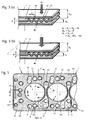
- FIG. 1 shows a partial plan view of a metallic gasket 1 using the example of a cylinder head gasket.
- a metallic gasket 1 is a three-layer seal with a gasket layer 2 and two cover layers 7 and 7 ', which are arranged on both surfaces 21 and 22 of the gasket layer 2.
- the cylinder head gasket 1 has a plurality of combustion chamber openings 3, only two of which are completely visible here.
- a plurality of further through openings 5 in the outer region of the sealing and cover layers are present, in which it are openings for oil and cooling water and screw openings, the latter being identified by reference numeral 51.
- the combustion chamber openings 3 are each surrounded by a sealing element 4 which has the form of a wave-shaped profiling 40, in which wave peaks 41 alternate with wave troughs 42.
- a sealing element 4 which has the form of a wave-shaped profiling 40, in which wave peaks 41 alternate with wave troughs 42.
- On each of the surfaces 21 and 22 of the gasket layer 2 four peaks 41 are present.
- Their vertices 43 have a distance a from each other which is in a range up to 2.0, preferably up to 1.7, more preferably up to 1.5 and particularly preferably up to 1.0 mm.
- the wave-shaped profiling 40 is produced by embossing the respective edge region of the gasket layer 2 around the passage opening 3 around. As a result, an increase in thickness compared to the original thickness d of the gasket layer 2 in the region of the undulating profiling 40 is achieved.
- FIGS. 3 (a) and 3 (b) illustrate this increase in thickness on the one hand in the non-installed state of the seal with a preload (force) of 2.4 N / mm 2 acts on the seal substantially perpendicular to the measurement ( FIG. 3 (a) ) as well as in the case of the built-in seal under load with an equivalent force of the screw ( FIG. 3 (b) ).
- a preload (force) of 2.4 N / mm 2 acts on the seal substantially perpendicular to the measurement ( FIG. 3 (a) ) as well as in the case of the built-in seal under load with an equivalent force of the screw ( FIG. 3 (b) ).
- the thickness difference ⁇ VL is derived from the difference of the height h of VL in the region of the wave-shaped profile 40 and the original thickness of the sealing layer d 2.
- the wave-shaped profile 40 according to the invention is designed so that on the one hand, has elastic properties, but also on the other hand, when subjected to a force that corresponds at least to the expected load during operation of the seal, leading to a permanent increase in the combustion chamber edge.
- This permanent elevation is determined by the fact that the cylinder head gasket 1 is first subjected to a force of 2.4 N / mm 2 in the region of the wave-shaped profiling 40.
- This force (marked here with VL) acts on the seal essentially perpendicular to the plane of the gasket layer 2. Substantially perpendicular here means that the force does not deviate more than 2 ° and in particular not more than 1 ° from the vertical.
- the resulting superelevation in the installed state ⁇ b is determined by a force equivalent to the screw force F is applied to the area of the wave-shaped profiling and the corresponding deformation is measured in the vertical direction.
- the so-called characteristic is determined, which indicates the thickness h b of the wave-shaped profiled area as a function of the applied force F.
- the preload VL is usually generated by having a punch from above perpendicular to the area of the undulating profiling is pressed
- the force F is applied to determine the characteristic by means of a flange.
- the elevation ⁇ b at the combustion chamber under installation conditions results from the height difference h b between the wave-shaped profiling under the action of force and the original thickness of the profiled layer, d.
- the sealing element 4 not only ensures elastic sealing of the combustion chamber opening 3, but at the same time also ensures an elevation along the combustion chamber opening 3, which results in the screws passed through the fastening means openings 51, with which the Cylinder head gasket 1 is clamped between the engine block and cylinder head, exert a clamping pressure, which is concentrated substantially in the area around the combustion chamber openings 3.
- the wave-shaped profiles 40 thus combine the functions of an elastic bead and a stopper and ensure by simultaneously existing elastic deformation and lasting supernatant for excellent tightness, which can be further improved by generating a topography in the circumferential direction around the combustion chamber openings 3.
- sealing elements 6 which consist of sealing beads made of elastomer. These sealing beads 6 are formed so high that they protrude beyond the outer surfaces 73 and 73 'of the cover plates 7 and 7'. This is in FIG. 4 to recognize that a cross section along the line CC in FIG. 1 shows.
- the cover plates 7 and 7 ' have recesses 72 which are large enough to accommodate the further passage openings 5 and their sealing elements 6.
- the Elastomerwülste 6 have a width of at least 0.5 mm.
- cover plates 7 and 7 ' serve at the same time as deformation limiter for the sealing elements 6 and prevent the elastomer can be further pressed than up to the height of the cover plates 7 and 7'.
- a common recess 72 in the cover plates 7, 7 ' is present.
- cover plates 7, 7 are also located in the region between adjacent passage openings 3 and the adjacent screw openings 51.
- the elastomeric sealing elements 6 not only surround the passage openings 5 in the hinterland of the seal, but they also extend over in the examples shown the web area between adjacent through holes 3 with their sealing elements. 4
- Another support element is located in the area parallel to the narrow edges of Poetry.
- This support element 10 runs essentially parallel to the edge region of the seal (here only the right sealing element is shown in the region next to the right-hand combustion chamber opening 3).
- the support member 10 is used in a conventional manner to prevent distortion between the engine block and cylinder head in this area.
- the support member 10 is also formed here in the form of a wave-shaped profiling. However, the wave crests and wave troughs are made lower than in the area of the wave-shaped profiles 40 around the combustion chamber openings 3. In addition, there are fewer wave crests and wave troughs.
- the gasket layer 2 which contains the annular profilings 40, is divided into several segments, of which the segment 23 can be seen completely, the segment 24 only partially.
- the segments each include two combustion chamber openings so that multiple segments can be assembled into cylinder head gaskets having four, six or more combustion chamber openings.
- the boundary region in which the segments 23 and 24 adjoin one another is marked with dashed lines and marked with the letter G.
- the cover plates 7 and 7 ' are integrally formed over the entire extent of the cylinder head gasket, so that they also cover the boundary region G.
- the cover plates 7 and 7 ' have no sealing or supporting elements and are completely flat.
- the surface area of the cover plate 7 is in FIG. 1 illustrated by the hatching.
- the second cover plate 7 ' which in FIG. 1 is not visible, is formed according to the cover plate 7.
- FIG. 5 shows a further example of a cylinder head gasket according to the invention in a partial plan view.
- This cylinder head gasket essentially corresponds to that of the FIG. 1 However, it differs in the arrangement of the other through holes 5, so the water and oil holes.
- the cover plates 7 and 7 'do not extend to the outer edge of the gasket layer 2, but leave the outer edge region 25 of the gasket layer 2 free. The reason is that along the outer edge of the gasket layer 2, a sealing bead 8 of elastomeric material rotates.
- FIG. 5 it should include several embodiments of the sealing bead 8 for reasons of simplification.
- the sealing beads 8 have a width of at least 0.5 mm.
- FIG. 6 shows a cross section along the line DD of FIG. 5 in a range from the outer edge of the gasket to a combustion chamber opening 3. Die The combustion chamber opening 3 is again surrounded by a wave-shaped profiling 40.
- FIG. 7 shows a partial cross section along the line EE of FIG. 5 ,
- the sealing of the combustion chamber openings corresponds to that of the preceding figures.
- the outer edge seal is different from the FIG. 6 not sharpened on the outer edge 26 of the gasket layer 2, but applied in the edge region 25 on both sides of the gasket layer 2 as a sealing bead 8 and 8 '.
- FIG. 8 shows a variant of the training of the area in FIG. 6 is shown.
- no outer edge sealing bead is provided, but the cover plates 7 and 7 'reach up to the outer edge of the gasket layer 2 zoom.
- this cross-section corresponds more closely to that of the FIG. 1 as that of the FIG. 5 .
- FIGS. 9 and 10 show Alternatives of the Hinterland support 10.
- the Hinterland support 10 in the embodiment according to FIG. 9 from a surface structuring of the surfaces 21 and 22 of the gasket layer 2.
- This surface structuring which is expediently also produced by embossing, consists for example of checkerboard-like elevations, which are separated by depressions.
- FIG. 10 is used as a hinterland support a strip-shaped pad. It is preferably a metallic support which has been fastened to the gasket layer 2 either by welding or a similar method, or a so-called hard coating, ie a coating of material which is difficult to compress.
- FIG. 11 shows a partial cross section along the outer edge region of in FIG. 5 represented seal, namely along the line HH.
- the cover plates 7 and 7 ' are not brought up to the outer edge of the gasket layer 2, but have a relatively large distance to this.
- the cover plates 7 and 7 'therefore can not act as a press protection for the sealing bead 8.
- the support elements 9 are metal sleeves which have a greater thickness than the thickness of the gasket layer 2 and project over the gasket layer 2 on both sides.
- the metal sleeves 9 are respectively inserted into the screw holes 51 which are adjacent to the outer edge of the gasket layer 2. Due to the greater thickness of the sleeves 9 in comparison to the thickness of the gasket layer 2, these act as anti-compression protection for the Elastomerwülste 8, 8 'at the sealing edge.
- FIGS. 12 to 14 serve the comparison of the flat gasket according to the invention and in particular the sealing of the combustion chamber openings 3 with the usual concepts in the prior art.
- the example according to the invention is in FIG. 13 shown in partial cross-sectional view. The figure essentially corresponds to the right area of FIG. 6 , FIGS. 12 and 14 show the same section, but with different sealing elements for the combustion chamber opening 3.
- the combustion chamber opening 3 is sealed by a plastically deformable multiple bead as a sealing element 4. At this multiple bead is followed by an insert with elastomeric beads 6, 6 ', wherein the insert is welded.
- the thickness of the multiple bead as a sealing element 4 is very large, so that the molded-in multiple bead has predominantly plastic, but only minimal elastic properties.
- the seal according to FIG. 14 on the other hand has a purely elastic bead as a sealing element 4. Without a stopper, however, this elastic bead can be completely flattened in the operation of the seal. A concentration of force at the combustion chamber is not possible without additional measures.
- FIG. 15 shows characteristics for the in FIGS. 12 to 14 illustrated sealing elements. Shown is the deformation of the sealing element against the load.
- the shaded bar illustrates the expected during operation of the seals in a particular engine minimum and maximum loads, so the actual working range of the respective sealing elements during operation of the seal.
- the plastic bead of the FIG. 12 has a higher stiffness, the resilience is low.
- the wave-shaped profiling as a sealing element in the seal according to the invention FIG. 13 both elastic and rigid behavior. It has a high rigidity combined with good springback properties and very consistent and good sealing performance throughout the typical working range.
Description
Die Erfindung betrifft eine metallische Flachdichtung, die sich insbesondere als Zylinderkopfdichtung für Nutzfahrzeuge eignet. Bei Zylinderkopfdichtungen kommt der Abdichtung der Brennraumöffnungen, bei Auspuffkrümmerdichtungen der der Brenngasöffnungen, eine besondere Bedeutung zu. Um eine sichere Abdichtung in diesem Bereich zu gewährleisten, ist es daher insbesondere bei Anwendungen, wie sie üblicherweise bei LKW-Dieselmotoren mit oder ohne Laufbuchsen vorgefunden werden, notwendig, die Schraubenkraft, mit der Zylinderkopf und Motorblock miteinander verbunden werden, am Brennraum zu konzentrieren. Um dies zu erreichen, ist es bei Zylinderkopfdichtungen für Verbrennungsmotoren mit geringem oder fehlendem Buchsenüberstand üblich, am Brennraumrand eine so genannte Überhöhung zu erzeugen. Dies bedeutet, dass im Bereich um die Brennraumöffnungen die Gesamtdicke der Dichtungslagen der Zylinderkopfdichtung einschließlich eines gegebenenfalls vorhandenen geringen Buchsenüber- oder unterstands größer ist als die Gesamtdicke der Dichtungslagen in weiter von den Brennraumöffnungen entfernt gelegenen Bereichen der Dichtung, dem so genannten Hinterland.The invention relates to a metallic flat gasket, which is particularly suitable as a cylinder head gasket for commercial vehicles. In cylinder head gaskets, the sealing of the combustion chamber openings, in the case of exhaust manifold gaskets of the fuel gas openings, is of particular importance. In order to ensure a secure seal in this area, it is therefore necessary, especially in applications that are commonly found in truck diesel engines with or without liners, to concentrate the bolt force with which the cylinder head and engine block are connected to one another at the combustion chamber. To achieve this, it is customary in the case of cylinder head gaskets for internal combustion engines with little or no bushing projection to produce a so-called superelevation at the combustion chamber edge. This means that in the area around the combustion chamber openings, the total thickness of the gasket layers of the cylinder head gasket, including an optionally present small bushing overhang or shelter, is greater than the total thickness of the gasket layers in regions of the gasket which are further away from the combustion chamber openings, the so-called hinterland.
Eine solche Überhöhung am Brennraumrand wird häufig durch Verwendung eines so genannten Stoppers erreicht. Bei diesen Stoppern handelt es sich üblicherweise um massive ringförmige Einlagen, die direkt am Brennraumrand entlang verlaufen. Die Höhe der Stopper ist im Allgemeinen so bemessen, dass sie, gegebenenfalls in Kombination mit der Dicke der im Bereich um die Brennraumöffnung vorhandenen Dichtungslagen, den Dichtspalt zwischen Motorblock und Zylinderkopf im Bereich um die Brennraumöffnung vollständig ausfüllen. Alternativ zum Einlegen eines separaten Rings kann der Stopper auch durch Umbiegen eines Randbereichs der Dichtungslage an der Brennraumöffnung hergestellt werden. Derartige Stopper weisen keinerlei elastische Eigenschaften auf. Um eine sichere Abdichtung der Brennraumöffnungen zu erreichen, werden Stopper deshalb üblicherweise in Kombination mit einem elastischen Dichtelement, im Allgemeinen einer Sicke, verwendet, die üblicherweise von der Brennraumöffnung aus gesehen radial außerhalb des Stoppers verläuft. Der Stopper dient in der Regel gleichzeitig auch als Abstützelement für die Sicke und verhindert deren vollständiges Abplatten beim Betrieb der Dichtung. Auch das Anbringen eines Stoppers radial hinter der Sicke alternativ oder zusätzlich zum Stopper am Brennraumrand ist aus dem Stand der Technik bekannt. Weiterhin gibt es Lösungen, bei denen eine elastische Sicke mit einem separaten starren Element so kombiniert wird, dass beide einen vergleichbaren radialen Abstand zum Brennraumrand aufweisen.Such an increase in the combustion chamber edge is often achieved by using a so-called stopper. These stoppers are usually massive annular inserts that run along the edge of the combustion chamber. The height of the stoppers is generally dimensioned such that, if appropriate in combination with the thickness of the sealing layers present in the area around the combustion chamber opening, they completely fill the sealing gap between the engine block and cylinder head in the area around the combustion chamber opening. As an alternative to inserting a separate ring, the stopper can also be produced by bending over an edge region of the gasket layer on the combustion chamber opening. Such stoppers have no elastic properties. Therefore, in order to achieve a secure sealing of the combustion chamber openings, stoppers are usually used in combination with an elastic sealing element, generally a bead, which extends radially outwardly of the stopper, as seen from the combustion chamber opening. The stopper is usually at the same time as a supporting element for the bead and prevents their complete Abplatten during operation of the seal. The attachment of a stopper radially behind the bead alternatively or in addition to the stopper on the combustion chamber edge is out of the standing known to the art. Furthermore, there are solutions in which an elastic bead is combined with a separate rigid element so that both have a comparable radial distance from the combustion chamber edge.
Der Aufbau der Stopper-Sicken-Dichtungen ist vergleichsweise kompliziert. Zudem ist es, um eine sichere Abdichtung der Brennraumöffnungen zu erhalten, häufig erforderlich, den Bereich der Zylinderkopfdichtung um die Brennraumöffnungen herum topographisch auszugestalten. Ohne eine solche topographische Ausbildung wäre der von den Befestigungsmitteln ausgeübte Zusammenspanndruck in Umfangsrichtung um die Brennraumöffnungen herum häufig unregelmäßig. Zum Befestigen des Zylinderkopfes am Motorblock sind üblicherweise um die Brennraumöffnung herum mehrere Schrauben verteilt. Im verbauten Zustand stellt sich zwischen den Schrauben üblicherweise ein größerer Abstand zwischen Zylinderkopf und Zylinderblock ein als an den Schrauben selbst. Als Folge hiervon vergrößert sich der von der zwischen Motorblock und Zylinderkopf angeordneten Zylinderkopfdichtung auszufüllende Dichtspalt. Dieser Dichtspaltvarianz wird durch eine entsprechende Topographie der Zylinderkopfdichtung um die Brennraumöffnungen herum Rechnung getragen. Es ist beispielsweise bekannt, die Höhe des Stoppers in Umfangsrichtung um die Brennraumöffnung der Größe des Dichtspalts folgend auszugestalten. Die Ausbildung einer derartigen Topographie in massiven Stoppern gestaltet sich jedoch oft aufwendig und schwierig.The construction of the stopper bead seals is relatively complicated. In addition, in order to obtain a secure seal of the combustion chamber openings, it is often necessary to design the region of the cylinder head gasket around the combustion chamber openings topographically. Without such a topographical design, the clamping pressure exerted by the fasteners in the circumferential direction around the combustion chamber openings would often be irregular. To fasten the cylinder head to the engine block, several screws are usually distributed around the combustion chamber opening. In the installed state, a larger distance between the cylinder head and cylinder block usually arises between the bolts than on the bolts themselves. As a consequence, the sealing gap to be filled by the cylinder head gasket arranged between the engine block and the cylinder head increases. This sealing gap variance is accommodated by a corresponding topography of the cylinder head gasket around the combustion chamber openings. For example, it is known to design the height of the stopper in the circumferential direction about the combustion chamber opening following the size of the sealing gap. The formation of such a topography in massive stoppers, however, often designed consuming and difficult.
Eine alternative Lösung zur Abdichtung von Brennraumöffnungen in Zylinderkopfdichtungen für Nutzfahrzeugmotoren besteht darin, anstelle einer Stopper-Sicken-Kombination eine rein plastische Sicke am Brennraumrand einzusetzen. Diese rein plastische Sicke, bei der es sich auch um eine Mehrfachsicke handeln kann, die in mehreren konzentrischen Ringen um die Brennraumöffnung verläuft, besitzt im Unterschied zu den Sicken der Stopper-Sicken-Dichtungen praktisch keine elastischen Eigenschaften. Dieser Mangel an Elastizität führt jedoch häufig zu nicht zufriedenstellenden Dichteigenschaften um die Brennraumöffnungen. Um die erforderliche Steifigkeit zu erhalten, sind die plastischen Sicken zudem häufig mit einem so genannten Hardcoating versehen oder der Sickenhohlraum ist mit einem versteifenden Material verfüllt. Dies erschwert und verteuert die Herstellung einer derartigen Dichtung. Die
Es bestand also ein Bedarf an einer metallischen Flachdichtung und insbesondere einer Zylinderkopfdichtung für Verbrennungsmotoren, welche bei einfachem Aufbau dennoch zu einer sicheren Abdichtung der Durchgangsöffnungen und insbesondere der Brennraumöffnungen im Fall von Zylinderkopfdichtungen führt. Aufgabe der Erfindung ist es entsprechend, eine derartige metallische Flachdichtung anzugeben.There was therefore a need for a metallic flat gasket and in particular a cylinder head gasket for internal combustion engines, which nevertheless leads to a secure sealing of the passage openings and in particular the combustion chamber openings in the case of cylinder head gaskets with a simple construction. The object of the invention is accordingly to provide such a metallic flat gasket.
Die Lösung dieser Aufgabe gelingt mit der metallischen Flachdichtung gemäß Anspruch 1. Bevorzugte Ausführungsvarianten dieser Flachdichtung sind in den Unteransprüchen beschrieben.The solution of this problem is achieved with the metallic flat gasket according to
Demnach betrifft die Erfindung eine metallische Flachdichtung mit mindestens einer Dichtungslage, die aus Metall mit einer Zugfestigkeit von mindestens 600 N/mm2 besteht und mindestens 4 Durchgangsöffnungen für Befestigungsmittel sowie wenigstens eine weitere Durchgangsöffnung für Schmier- oder Kühlmittel aufweist, welche von einem Abdichtelement aus Elastomer umschlossen wird. Zudem besitzt sie wenigstens eine Brennraumdurchgangsöffnung, die einen Durchmesser von kleiner als 200 mm besitzt und von einem elastisch verformbaren Abdichtelement umschlossen wird. Das Abdichtelement ist in Form einer wellenförmigen Profilierung in der Dichtungslage in der Weise ausgebildet, dass auf jeder der Oberflächen der Dichtungslage wenigstens jeweils zwei Wellenberge und zwei Wellentäler vorhanden sind. In Einzelfällen kommt es dabei vor, dass nur 1 1/2 Wellenperioden die Brennraumdurchgangsöffnung vollständig umlaufend umschließen. Dabei ist die Dicke der Dichtungslage im Bereich des Abdichtelements im unbelasteten Zustand größer als die originäre Dicke der Dichtungslage. Außer dieser wellenförmigen Profilierung sind für die Brennraumdurchgangsöffnung keine weiteren Abdicht- oder Abstützelemente in der Flachdichtung vorhanden. Das Abdichtelement, also die wellenförmige Profilierung, ist dabei so ausgelegt, dass zwischen der originären Dicke der Dichtungslage und der Dicke im Bereich des Abdichtelements auch dann noch ein Dickenunterschied besteht, wenn das Abdichtelement einer Belastung mit einer Linienpressung von 500 bis 2800 N/mm in einer zur Ebene der Dichtungslage im Wesentlichen senkrechten Richtung ausgesetzt wird. Konkret ist im eingebauten Zustand die Dicke der Dichtungslage im Bereich des Abdichtelements um 0,05 bis 0,3 mm, bevorzugt 0,05 bis 0,2 mm, größer als die originäre Dicke der Dichtungslage. Im Wesentlichen senkrecht bedeutet, dass die Krafteinwirkung nicht mehr als 2 ° und insbesondere nicht mehr als 1 ° aus der Senkrechten abweicht.Accordingly, the invention relates to a metallic flat gasket with at least one gasket layer, which consists of metal with a tensile strength of at least 600 N / mm 2 and at least 4 through holes for fastening means and at least one further passage opening for lubricant or coolant, which of a sealing element made of elastomer is enclosed. In addition, it has at least one combustion chamber passage opening which has a diameter of less than 200 mm and is enclosed by an elastically deformable sealing element. The sealing element is designed in the form of a wave-shaped profiling in the gasket layer in such a way that on each of the surfaces of the gasket layer at least two peaks and two wave troughs are present. In individual cases, it happens that only 1 1/2 shaft periods enclose the combustion chamber passage opening completely encircling. In this case, the thickness of the gasket layer in the region of the sealing element in the unloaded state is greater than the original thickness of the gasket layer. Apart from this wave-shaped profiling, no further sealing or supporting elements are present in the flat gasket for the combustion chamber passage opening. The sealing element, so the wave-shaped profiling, it is designed so that between the original thickness of the gasket layer and the thickness in the region of the sealing element even then there is a difference in thickness when the sealing element of a load with a line pressure of 500 to 2800 N / mm in one is exposed to the plane of the gasket layer substantially perpendicular direction. Specifically, in the installed state, the thickness of the gasket layer in the region of the sealing element by 0.05 to 0.3 mm, preferably 0.05 to 0.2 mm, greater than the original thickness of the gasket layer. Substantially perpendicular means that the force does not deviate more than 2 ° and in particular not more than 1 ° from the vertical.
Eine solche Ausgestaltung des Abdichtelements um die Durchgangsöffnung bedeutet, dass das Abdichtelement gleichzeitig elastische und starre Eigenschaften aufweist. Die starren Eigenschaften sind dabei so eingestellt, dass auch bei einer Krafteinwirkung der vorhandenen Schraubenkraft im Bereich des Abdichtelements eine während des Betriebs der Dichtung dauerhaft bestehen bleibende Überhöhung am Brennraumrand gebildet wird. Diese dauerhafte Überhöhung im Bereich der Durchgangsöffnung erlaubt es, die Schraubenkräfte in diesem Bereich zu konzentrieren und für den nötigen hohen Zusammenspanndruck in diesem Bereich zu sorgen. Die wellenförmige Profilierung als Abdichtelement kann auf diese Weise die Funktion eines massiven Stoppers übernehmen. Gleichzeitig weist die wellenförmige Profilierung aber auch elastische Eigenschaften auf. Diese elastischen Eigenschaften ermöglichen es der wellenförmigen Profilierung als dem Abdichtelement der Durchgangsöffnung, Dichtspaltänderungen, z.B. von 5-15 µm, während des Betriebs der Dichtung elastisch zu folgen und so auch in diesem Fall eine ausgezeichnete Dichtigkeit um die Durchgangs öffnung herum zu gewährleisten. Aufgrund der hohen Elastizität des Abdichtelements ist es sogar möglich, die Schraubenkräfte auf ein Mindestmaß zu reduzieren, ohne dass darunter die Dichtigkeit leidet.Such a configuration of the sealing element around the passage opening means that the sealing element simultaneously has elastic and rigid properties. The rigid properties are adjusted so that even with a force of the existing bolt force in the region of the sealing element during the operation of the seal permanently persisting increase in the combustion chamber edge is formed. This permanent increase in the area of the passage opening allows to concentrate the screw forces in this area and to provide the necessary high clamping pressure in this area. The wavy profiling as a sealing element can take over the function of a massive stopper in this way. At the same time, the wave-shaped profiling also has elastic properties. These elastic properties make it possible for the wavy profiling as the sealing element of the through-opening, sealing gap changes, for example of 5-15 μm, to follow elastically during the operation of the seal and thus also in this case an excellent tightness around the passage to ensure opening around. Due to the high elasticity of the sealing element, it is even possible to reduce the screw forces to a minimum, without undermining the tightness.
Die Erfindung vereint in dem spezifisch ausgebildeten Abdichtelement die Funktionen eines elastischen Elements (beispielsweise einer Sicke) und eines (starren) Stoppers einer herkömmlichen Dichtung in einem einzigen Element. Dadurch können Aufbau und Herstellung gegenüber den herkömmlichen Dichtungen stark vereinfacht werden. Zudem lässt sich über die Wahl der Anzahl Wellenberge und Wellentäler die Steifigkeit an die benötigten Bedürfnisse anpassen. Erfindungsgemäß ist die wellenförmige Profilierung so ausgelegt, dass auf jeder der Oberflächen der Dichtungslage wenigstens zwei Wellenberge und zwei Wellentäler vorhanden sind. Es sind also für jede Oberfläche wenigstens zwei um die Durchgangsöffnung verlaufende Pressungslinien vorhanden. Bevorzugt werden mehr als zwei Wellenberge und zwei Wellentäler pro Oberfläche der Dichtungslage in diese eingeformt, so dass entsprechend mehr ringförmige Pressungslinien um die Öffnung herum entstehen. Die Vielzahl dieser Pressungslinien sorgt für eine ausreichende Dichtigkeit im Bereich um die Durchgangsöffnung.The invention combines in the specifically embodied sealing element the functions of an elastic element (for example a bead) and a (rigid) stopper of a conventional seal in a single element. As a result, construction and production over the conventional seals can be greatly simplified. In addition, the rigidity can be adapted to the required needs by selecting the number of wave crests and troughs. According to the invention, the wave-shaped profiling is designed so that at least two wave crests and two wave troughs are present on each of the surfaces of the gasket layer. So there are at least two extending around the through-hole pressure lines for each surface. Preferably, more than two wave peaks and two wave troughs per surface of the gasket layer are molded into them, so that correspondingly more annular pressure lines are formed around the opening. The large number of these pressure lines ensures sufficient tightness in the area around the passage opening.
Die Ausbildung der wellenförmigen Profilierung kann in vielfältiger Weise entsprechend den jeweiligen Anforderungen variiert werden. Üblicherweise wird der Verlauf der Wellenberge und Wellentäler um die Durchgangsöffnung herum dem Verlauf der Außenkontur der Durchgangsöffnung folgen. Im Fall einer kreisrunden Öffnung beispielsweise können die Wellenberge und Wellentäler also in konzentrischen Kreisringen um die Durchgangsöffnung herum verlaufen. Es sind jedoch auch andere Grundrissformen wie beispielsweise ovale, polyedrische oder sonstige regelmäßige oder unregelmäßige Verlaufsformen denkbar. Aus Platzgründen verlaufen Wellenberge und Wellentäler bevorzugt entlang konzentrischer Linien, aber auch dies ist nicht unbedingt erforderlich.The formation of the wave-shaped profiling can be varied in many ways according to the respective requirements. Usually, the course of the wave crests and wave troughs around the passage opening will follow the course of the outer contour of the passage opening. In the case of a circular opening, for example, the wave crests and wave troughs can thus run around the passage opening in concentric circular rings. However, other plan shapes such as oval, polyhedral or other regular or irregular courses are conceivable. For reasons of space, wave crests and wave troughs preferably run along concentric lines, but even this is not absolutely necessary.
Auch der Querschnitt der Wellenberge und Wellentäler der wellenförmigen Profilierung in einem Schnitt in Radialrichtung kann grundsätzlich beliebig gestaltet werden. Bevorzugte Formen weisen ein sinus-, trapez- oder zickzackförmiges Querschnittsprofil auf. Es sind jedoch auch Abwandlungen dieser Formen, beispielsweise mit unterschiedlich steil ansteigenden Flanken, abgeplatteten Scheiteln usw. denkbar. Die Querschnittsform kann für alle Wellenberge und Wellentäler gleich sein oder sich für einzelne Wellenberge und/der Wellentäler unterscheiden. Außerdem ist es möglich, die Querschnittsform im Verlauf eines einzelnen Wellenberges oder Wellentales zu verändern.The cross section of the wave crests and wave troughs of the wave-shaped profiling in a section in the radial direction can basically be designed arbitrarily. Preferred shapes have a sinusoidal, trapezoidal or zigzag cross-sectional profile. However, there are also variations of these forms, for example, with different steeply rising flanks, flattened vertices, etc. conceivable. The cross-sectional shape may be the same for all wave crests and wave troughs or may differ for individual wave crests and / or troughs. In addition, it is possible to change the cross-sectional shape in the course of a single wave crest or wave trough.
Die wellenförmige Profilierung als Abdichtelement der Durchgangsöffnung eignet sich entsprechend in hervorragender Weise, um eine Topographie im Bereich um die Durchgangsöffnung zu erzeugen. Auf diese Weise können die Abdichteigenschaften gezielt den jeweils vorgefundenen Bedingungen angepasst werden. Die Variation der Eigenschaften wie beispielsweise Höhe und/oder Steifigkeit der wellenförmigen Profilierung kann sowohl in Radial- als auch in Umfangsrichtung oder in beiden Richtungen variiert werden. Bevorzugt geschieht diese Anpassung durch Variation wenigstens einer der folgenden Eigenschaften: der Höhe der Wellenberge, der Querschnittsform der Wellenberge und/oder der Wellentäler, dem Abstand zwischen benachbarten Wellenbergen und der Materialstärke im Bereich der Wellenberge und/oder Wellentäler. Bei der Variation der Höhe der Wellenberge ist es auch möglich, dass ein Wellenberg in Umfangsrichtung in seiner Höhe bereichsweise auf Null reduziert wird, also sozusagen abschnittsweise in der Dichtungslage verschwindet. Die Höhenänderung im Rahmen der Topographie beträgt bevorzugt bis zu 0,03 mm und erfolgt in jedem Fall so, dass die Überhöhung am Rand der Durchgangsöffnung im beanspruchten Bereich von 0,05 bis 0,3 mm liegt. Eine größere Höhe der Wellenberge, steiler ansteigende Flanken der Wellenberge und der Wellentäler, ein geringerer Abstand zwischen benachbarten Wellenbergen und eine größere Materialstärke führen dabei zu einer erhöhten Steifigkeit der wellenförmigen Profilierung.The corrugated profiling as a sealing element of the passage opening is correspondingly in an excellent manner to produce a topography in the region around the passage opening. In this way, the sealing properties can be specifically adapted to the particular conditions encountered. The variation of the properties such as height and / or stiffness of the wave-shaped profiling can be varied both in the radial and in the circumferential direction or in both directions. This adaptation preferably takes place by varying at least one of the following properties: the height of the wave crests, the cross-sectional shape of the wave crests and / or the troughs, the distance between adjacent wave crests and the material thickness in the region of the wave crests and / or troughs. In the variation of the height of the wave crests, it is also possible that a wave crest in the circumferential direction is partially reduced in its height to zero, so it disappears, so to speak in sections in the gasket layer. The change in height in the context of the topography is preferably up to 0.03 mm and takes place in any case so that the elevation at the edge of the passage opening in the claimed range of 0.05 to 0.3 mm. A greater height of the wave peaks, steeper rising flanks of the wave crests and troughs, a smaller distance between adjacent wave crests and a greater material thickness lead to an increased rigidity of the wave-shaped profiling.
Um die erforderliche dauerhafte Überhöhung am Brennraumrand sicher zu stellen, weist das Abdichtelement in Form der wellenförmigen Profilierung nicht nur elastische, sondern auch plastische Eigenschaften auf. Gegenüber der Elastizität herkömmlicher Sicken ist die Elastizität der wellenförmigen Profilierung daher geringer. Dies zeigt sich auch darin, dass die Abmessungen der wellenförmigen Profilierung kleiner sind als die Abmessungen einer herkömmlichen Sicke oder Mehrfachsicke. So liegt der Abstand der Scheitelpunkte benachbarter Wellenberge der wellenförmigen Profilierung zweckmäßig in einem Bereich bis zu 2,0, bevorzugt 1,7, besonders bevorzugt 1,5, insbesondere 1,0 mm. Weisen die Wellenberge keinen Scheitelpunkt, sondern einen abgeplatteten Scheitelbereich auf, wird der Abstand zwischen den Mittelpunkten dieser Scheitelbereiche gemessen und zwar immer in einer zur Ebene der Dichtungslage parallelen Ebene. Wenn ein Wellenberg in Umfangsrichtung in seiner Höhe auf Null reduziert ist, wird der Abstand zwischen den benachbarten Wellenbergen selbstverständlich in den Bereichen gemessen, in denen der Wellenberg eine größere Höhe als Null besitzt. Variiert der Abstand benachbarter Wellenberge in Umfangsrichtung zueinander, liegen alle diese Abstände zweckmäßig im angegebenen Bereich.In order to ensure the required permanent elevation at the edge of the combustion chamber, the sealing element in the form of wave-shaped profiling has not only elastic but also plastic properties. Compared to the elasticity of conventional beads, the elasticity of the undulating profiling is therefore lower. This is also reflected in the fact that the dimensions of the wave-shaped profiling are smaller than the dimensions of a conventional bead or multiple bead. Thus, the distance of the vertices of adjacent peaks of the wave-shaped profiling expediently in a range up to 2.0, preferably 1.7, more preferably 1.5, in particular 1.0 mm. If the wave crests do not have a vertex but a flattened vertex area, the distance between the centers of these vertex areas is always measured in a plane parallel to the plane of the gasket layer. When a wave crest in the circumferential direction is reduced in its height to zero, of course, the distance between the adjacent crests is measured in the areas in which the crest has a height greater than zero. If the distance between neighboring wave peaks varies in the circumferential direction relative to one another, all these distances are expediently within the given range.
Die wellenförmige Profilierung als Abdichtelement ist in der Dichtungslage selbst ausgebildet. Dies bedeutet, dass die wellenförmige Profilierung nicht in einem separaten Teil erzeugt ist, sondern integral und einstückig in der Dichtungslage. Es müssen also keine Einlageringe verwendet werden, wie dies üblicherweise bei herkömmlichen Stoppern der Fall ist. Dies vereinfacht und verbilligt die Herstellung der Dichtung erheblich. Die wellenförmige Profilierung wird so erzeugt, dass in Richtung beider Oberflächen der Dichtungslage Wellenberge und Wellentäler ausgebildet sind, diese müssen dabei nicht symmetrisch sein. Die Dicke der Dichtungslage im Bereich der wellenförmigen Profilierung ist daher größer als die originäre Dicke der Dichtungslage, also die Dicke der Dichtungslage vor dem Einformen der Wellenberge und Wellentäler. Die Dicke der Dichtungslage im Bereich der wellenförmigen Profilierung wird dabei als der Abstand zwischen zwei Tangentialebenen gemessen, die jeweils parallel zur Ebene der Dichtungslage an den jeweils höchsten Wellenberg, der über die eine und die andere Seite der Dichtungslage vorsteht, angelegt werden.The wave-shaped profiling as a sealing element is formed in the gasket layer itself. This means that the wave-shaped profiling is not produced in a separate part, but integral and integral in the gasket layer. So no insertion rings must be used, as is usually the case with conventional stoppers. This considerably simplifies and reduces the cost of manufacturing the seal. The wave-shaped profiling is generated so that wave peaks and wave troughs are formed in the direction of both surfaces of the gasket layer, these need not be symmetrical. The thickness of the gasket layer in the region of the wave-shaped profiling is therefore greater than the original thickness of the gasket layer, ie the thickness of the gasket layer prior to molding of the wave crests and wave troughs. The thickness of the gasket layer in the area of the undulating profiling is measured as the distance between two tangential planes, which are each applied parallel to the plane of the gasket layer to the respective highest crest which projects beyond the one and the other side of the gasket layer.
Der Überstand des profilierten Bereichs beträgt erfindungsgemäß im eingebauten Zustand mindestens 0,05 mm. Im kalten Zustand betragen die Schraubenkräfte, die auf die Dichtung einwirken, pro Schraube 50-220 kN, bevorzugt 60-200 kN und besonders bevorzugt 100-200 kN, oder ausgedrückt als Linienpressung 500-2800 N/mm, bevorzugt 800-2500 N/mm, besonders bevorzugt 800-1500 N/mm. Die Linienpressung bezieht sich dabei auf die mittlere Umlauflänge der wellenförmigen Profilierung. Die mittlere Umlauflänge ist die Erstreckung in Umfangsrichtung um die Brennraumöffnung in der Mitte (bei der halben Breite) der Profilierung. Im Labor wird die Höhe des profilierten Bereichs so ermittelt, dass dieser Bereich mit einer Kraft im Wesentlichen senkrecht belastet wird. Im Wesentlichen senkrecht bedeutet, dass die Schraubenkrafteinwirkung nicht mehr als 2° und insbesondere nicht mehr als 1° aus der Senkrechten abweicht. Der Überstand beträgt unter Vorlastbedingungen, d.h. unter dem für reproduzierbare Messungen mindestens notwendigen Druck von 2,4 N/mm2, 0,05 bis 0,35 mm, bevorzugt 0,07 bis 0,32 mm. Bei Simulation der o.g. Krafteinwirkung im Einbauzustand beträgt die dauerhafte Überhöhung der wellenförmigen Profilierung von 0,05 bis 0,3 mm, bevorzugt 0,05 bis 0,2 mm.The supernatant of the profiled area is according to the invention in the installed state at least 0.05 mm. In the cold state, the screw forces acting on the seal are 50-220 kN per screw, preferably 60-200 kN and particularly preferably 100-200 kN, or expressed as line pressure 500-2800 N / mm, preferably 800-2500 N / mm, more preferably 800-1500 N / mm. The line pressure refers to the mean circumferential length of the wave-shaped profiling. The mean circumferential length is the extent in the circumferential direction around the combustion chamber opening in the middle (at half the width) of the profiling. In the laboratory, the height of the profiled area is determined so that this area is loaded with a force substantially vertically. Substantially perpendicular means that the force of the bolt does not deviate more than 2 ° and in particular not more than 1 ° from the vertical. The supernatant is under preloading conditions, ie below the pressure of 2.4 N / mm 2 which is at least necessary for reproducible measurements, 0.05 to 0.35 mm, preferably 0.07 to 0.32 mm. In simulation of the above-mentioned force in the installed state, the permanent elevation of the wave-shaped profiling of 0.05 to 0.3 mm, preferably 0.05 to 0.2 mm.
Bevorzugt wird die wellenförmige Profilierung durch Prägen erzeugt. Grundsätzlich entspricht ein Wellenberg auf der einen Oberfläche der Dichtungslage einem Wellental auf der anderen Oberfläche und umgekehrt. Eine Topographie kann dabei mit dem Einprägen der Profilierung in die Dichtungslage erzeugt werden. Es sind jedoch auch andere Herstellungsverfahren wie beispielsweise Tiefziehen, Hydroforming oder Rändeln denkbar.Preferably, the wave-shaped profiling is produced by embossing. Basically, a wave crest on one surface of the sealing layer corresponds to a wave trough on the other surface and vice versa. A topography can be generated by impressing the profiling in the gasket layer. However, other production methods such as deep drawing, hydroforming or knurling are conceivable.
Um sowohl die erforderlichen elastischen als auch starren Eigenschaften der wellenförmigen Profilierung zu erzielen, wird für die Dichtungslage zweckmäßig ein relativ dickes Metallblech verwendet. Bevorzugt sind Dicken im Bereich von 0,2 bis 1,5 mm, wobei für mehrlagige Dichtungen Blechdicken von 0,3 bis 1,0 mm und für einlagige Dichtungen 0,8 bis 1,2 mm bevorzugt sind. Zudem weist das Metall eine relativ hohe Zugfestigkeit auf, die bei mindestens 600 N/mm2 und insbesondere bei mindestens 1000 N/mm2 liegt. Ein bevorzugtes Material für die Dichtungslage ist Stahl. Die Erfindung erlaubt die Verwendung relativ preiswerter Stähle wie beispielsweise herkömmlicher Kohlenstoffstähle oder kaltgewalzter Kohlenstoffstähle (z.B. C590, C75). Sind stärker ausgeprägte elastische Eigenschaften gefordert, kann auch Federstahl verwendet werden. Geeignete Stähle sind beispielsweise auch Edelstähle, insbesondere diejenigen der Typennummern 1,4310, 1,4372, 1,4301 oder 1,4303. Durch geeignete Auswahl des Materials selbst, der Materialstärke sowie der Art der Ausbildung der wellenförmigen Profilierung kann die Steifigkeit des Abdichtelements auf den speziellen Anwendungsfall gezielt abgestimmt werden. Auf die verschiedenen Möglichkeiten bei der Ausbildung der wellenförmigen Profilierung wurde bereits vorstehend hingewiesen. Bei Verwendung von federhartem Stahl kann beispielsweise durch Verjüngung der Flanken, also Verringerung der Materialdicke im Bereich der Flanken der Wellenberge und Wellentäler, eine stärkere Versteifung eingestellt werden. Im Unterschied zu den plastisch verformbaren Sicken des Standes der Technik ist es bei der Erfindung nicht erforderlich, die Wellentäler mit einem Material wie beispielsweise Elastomer auszufüllen, um die Steifigkeit der Sicken zu erhöhen. Die Verwendung solcher Füllmaterialien oder so genannter Hardcoatings für den Bereich der wellenförmigen Profilierung ist im Rahmen der Erfindung nicht bevorzugt. Die Steifigkeit der wellenförmigen Profilierung wird ausschließlich durch Auswahl des Materials und Formgebung der Profilierung selbst eingestellt.In order to achieve both the required elastic and rigid properties of the wave-shaped profiling, a relatively thick metal sheet is suitably used for the gasket layer. Preference is given to thicknesses in the range of 0.2 to 1.5 mm, with sheet thicknesses of 0.3 to 1.0 mm being preferred for multilayer gaskets and 0.8 to 1.2 mm being preferred for single-layer gaskets. moreover The metal has a relatively high tensile strength, which is at least 600 N / mm 2 and in particular at least 1000 N / mm 2 . A preferred material for the gasket layer is steel. The invention allows the use of relatively inexpensive steels such as conventional carbon steels or cold rolled carbon steels (eg C590, C75). If more pronounced elastic properties are required, spring steel can also be used. Suitable steels are, for example, also stainless steels, in particular those of the type numbers 1.4310, 1.4337, 1.4301 or 1.4303. By suitable selection of the material itself, the material thickness and the nature of the formation of the wave-shaped profiling, the rigidity of the sealing element can be tailored to the specific application. The various possibilities in the formation of the wave-shaped profiling has already been mentioned above. When using spring-hard steel, for example by rejuvenation of the flanks, so reducing the material thickness in the flanks of the wave crests and troughs, a stronger stiffening can be adjusted. In contrast to the plastically deformable beads of the prior art, it is not necessary in the invention to fill the troughs with a material such as elastomer in order to increase the rigidity of the beads. The use of such fillers or so-called hard coatings for the field of undulating profiling is not preferred within the scope of the invention. The rigidity of the undulating profiling is set exclusively by selecting the material and shaping the profiling itself.
Wie bereits erwähnt, wird die wellenförmige Profilierung in die Dichtungslage eingearbeitet und nicht als separat gefertigter Ring in die Dichtungslage eingesetzt bzw. aufgeschweißt. Dies bedeutet jedoch nicht zwangsläufig, dass die Dichtungslage insgesamt einstückig sein muss. Insbesondere bei sehr großflächigen Dichtungen kann es bevorzugt sein, die Dichtungslage, in welcher die wellenförmige Profilierung erzeugt ist, aus mehreren Segmenten zusammenzusetzen. Dabei umfasst ein Segment, das die Durchgangsöffnung mit der wellenförmigen Profilierung enthält, jedoch wenigstens einen Bereich, der sich von der Durchgangsöffnung nach außen erstreckt und mindestens einen Teil der die Durchgangsöffnung umgebenden Befestigungsmittelöffnungen enthält. Das Segment muss dabei nicht bis zum Dichtungsaußenrand reichen. Ist die Dichtungslage in mehrere Segmente aufgeteilt, sind diese bevorzugt möglichst gleichförmig gestaltet. Auf diese Weise ist es möglich, in Modulbauweise zum Beispiel verschieden große Dichtungen durch Aneinanderreihung der Segmente aufzubauen. Ein solches Vorgehen ist insbesondere bei Zylinderkopfdichtungen von Vorteil. Hier kann die Dichtungslage beispielsweise quer zu den Längsseiten geteilt sein, so dass sich Segmente ergeben, welche ein oder zwei Zylinderöffnungen enthalten. Durch Aneinanderreihen von Segmenten mit zwei Zylinderöffnungen beispielsweise können auf diese Weise Dichtungslagen für 4-Zylindermotoren, 6-Zylindermotoren usw. aufgebaut werden. Alternativ oder zusätzlich ist es möglich, im so genannten Hinterland der Dichtungslage, also in einem Bereich außerhalb der von der wellenförmigen Profilierung umgebenen Durchgangsöffnung, so genannte Inserts in Öffnungen der Dichtungslage einzusetzen. Der Bereich der wellenförmigen Profilierung selbst jedoch ist, wie bereits erwähnt, nicht als Insert ausgebildet.As already mentioned, the wave-shaped profiling is incorporated in the gasket layer and not used or welded as a separately manufactured ring in the gasket layer. However, this does not necessarily mean that the gasket layer as a whole must be one piece. In particular, in the case of very large-area seals, it may be preferable to assemble the sealing layer, in which the corrugated profiling is produced, from a plurality of segments. In this case, however, a segment which contains the passage opening with the wave-shaped profiling comprises at least one area which extends outwards from the passage opening and contains at least part of the fastener openings surrounding the passage opening. The segment does not have to reach the outer edge of the seal. If the gasket layer is divided into several segments, these are preferably designed as uniform as possible. In this way, it is possible to construct, for example, different sized seals by stringing together the segments in modular construction. Such an approach is particularly advantageous in cylinder head gaskets. Here, the gasket layer, for example, be divided transversely to the longitudinal sides, so that there are segments containing one or two cylinder openings. By juxtaposing segments with two cylinder openings, for example, sealing layers for 4-cylinder engines, 6-cylinder engines, etc. can be built up in this way. Alternatively or additionally, it is possible In the so-called hinterland of the gasket layer, so in an area outside the passage opening surrounded by the wave-shaped profiling, so-called inserts insert into openings of the gasket layer. However, the area of the wave-shaped profiling itself, as already mentioned, is not formed as an insert.
Die erfindungsgemäße metallische Flachdichtung wird üblicherweise mehr als nur eine einzige Brennraumdurchgangsöffnung aufweisen. Beispielsweise können mehrere von einer wellenförmigen Profilierung umgebene Brennraumdurchgangsöffnungen vorhanden sein. Zudem kann die Dichtungslage Durchgangsöffnungen anderen Typs aufweisen, die nachfolgend als weitere Durchgangsöffnungen bezeichnet werden. Ist die metallische Flachdichtung eine Zylinderkopfdichtung, handelt es sich bei den von der wellenförmigen Profilierung umgebenen Durchgangsöffnungen um die Brennraumöffnungen. Bei den weiteren Durchgangsöffnungen kann es sich um Öffnungen für Kühlwasser und Öl sowie um Schraubenöffnungen handeln. Müssen diese weiteren Durchgangsöffnungen ebenfalls von Dichtelementen umgeben werden, werden hierfür häufig keine wellenförmigen Profilierungen als Abdichtelemente verwendet, sondern andere elastisch verformbare Dichtelemente wie beispielsweise Sicken oder Wülste aus Elastomer.The metallic flat gasket according to the invention will usually have more than just a single combustion chamber passage opening. For example, there may be a plurality of combustion chamber passage openings surrounded by a wave-shaped profiling. In addition, the gasket layer can have through openings of another type, which are referred to below as further through-openings. If the metallic flat gasket is a cylinder head gasket, the passage openings surrounded by the wave-shaped profiling are the combustion chamber openings. The further through openings may be openings for cooling water and oil as well as screw openings. If these further passage openings must likewise be surrounded by sealing elements, wave-shaped profilings are frequently not used as sealing elements for this purpose, but other elastically deformable sealing elements, such as, for example, beads or beads of elastomer.
Zudem kann die erfindungsgemäße metallische Flachdichtung mehr als nur eine Dichtungslage aufweisen. Grundsätzlich ist es dabei denkbar, weitere Dichtungslagen mit einer wellenförmigen Profilierung als Abdichtelement einer Durchgangsöffnung zu verwenden. Dies ist jedoch nicht bevorzugt. Als weitere Dichtungslagen werden vielmehr eine oder mehrere Dichtungslagen verwendet, die sich in ihrer Art von der Dichtungslage mit wellenförmiger Profilierung unterscheiden. Bei den weiteren Dichtungslagen handelt es sich zum Beispiel um metallische Dichtungslagen, die weitgehend frei sind von Stopper- oder sonstigen Abstützelementen. In einer bevorzugten Variante ist die wenigstens eine weitere Dichtungslage vollkommen plan. Bei den weiteren Dichtungslagen kann es sich um Distanz- und/oder Deckbleche handeln. Zusätzlich oder alternativ zu diesen weiteren Dichtungslagen können andere Dichtungslagen vorhanden sein, welche Funktionselemente aufweisen. Bei den Funktionselementen kann es sich beispielsweise um elastische Dichtelemente, insbesondere um in die Dichtungslage eingeformte Sicken, Stopper- oder sonstige Abstützelemente handeln. Diese befinden sich dann jedoch nicht in denjenigen Bereichen, die der wellenförmigen Profilierung gegenüberliegen und umschließen auch keine der von den wellenförmigen Profilierungen umgebene Brennraumöffnung einzeln, d.h. sie wirken nicht als Abdichtelemente für diese. Die Anzahl der weiteren Dichtungslagen ist grundsätzlich beliebig. Bevorzugt ist es jedoch, wenn die erfindungsgemäße Flachdichtung lediglich eine oder maximal zwei weitere Dichtungslagen enthält. Diese Dichtungslagen werden nachfolgend als Deckbleche bezeichnet, da sie bevorzugt auf einer oder beiden Oberflächen der mit der wellenförmigen Profilierung versehenen Dichtungslage angeordnet sind. Die Flächenausdehnung der weiteren Dichtungslagen kann derjenigen der Dichtungslage mit der wellenförmigen Profilierung entsprechen oder sich von dieser unterscheiden. Die in der Dichtungslage mit der wellenförmigen Profilierung vorhandenen Durchgangsöffnungen sind korrespondierend in den weiteren Dichtungslagen ebenfalls vorhanden. Die Durchgangsöffnungen schließen dabei häufig nicht exakt bündig miteinander ab. Dies ist einerseits auf Stanztoleranzen bei der Fertigung zurückzuführen, andererseits kann es für das Zusammenfügen der verschiedenen Lagen auch notwendig sein, einen kleinen, aber merkbaren Größenunterschied vorzusehen.In addition, the metallic flat gasket according to the invention can have more than just one gasket layer. In principle, it is conceivable to use further gasket layers with a wave-shaped profiling as a sealing element of a passage opening. However, this is not preferred. As a further gasket layers one or more gasket layers are used, which differ in their kind from the gasket layer with wavy profiling. The other gasket layers are, for example, metallic gasket layers which are largely free of stopper or other support elements. In a preferred variant, the at least one further gasket layer is completely flat. The other gasket layers may be spacer and / or cover plates. In addition or as an alternative to these further gasket layers, other gasket layers may be present which have functional elements. The functional elements can be, for example, elastic sealing elements, in particular beads formed in the sealing layer, stopper or other supporting elements. However, these are then not in those areas which are opposite to the wave-shaped profiling and also enclose none of the surrounded by the wave-shaped profiling combustion chamber opening individually, ie they do not act as sealing elements for this. The number of further gasket layers is basically arbitrary. However, it is preferred if the flat gasket according to the invention contains only one or at most two further gasket layers. These gasket layers are hereinafter referred to as cover plates, as they are preferably on one or both surfaces are provided with the wave-shaped profiling gasket layer. The areal extent of the further gasket layers may correspond to or differ from that of the gasket layer with the wave-shaped profiling. The existing in the gasket layer with the wave-shaped profiling through holes are also present corresponding to the other gasket layers. The through holes often do not close flush with each other exactly. On the one hand, this is due to punching tolerances in the production, on the other hand, it may also be necessary for the joining of the different layers to provide a small but noticeable difference in size.
Bevorzugt ist das wenigstens eine Deckblech so auf der Oberfläche der Dichtungslage angeordnet, dass es den Bereich der wellenförmigen Profilierung überdeckt. Bevorzugt ist das Deckblech in diesem Bereich eben. Dies hat zum Einen den Vorteil, dass das wenigstens eine Deckblech eine plane und glatte Auflagefläche für die wellenförmige Profilierung bereitstellt. Außerdem verhindert das Deckblech, dass sich die Scheitelbereiche der Wellenberge in die abzudichtenden Gegenflächen eingraben können.Preferably, the at least one cover plate is arranged on the surface of the gasket layer such that it covers the area of the wave-shaped profiling. Preferably, the cover plate is flat in this area. On the one hand, this has the advantage that the at least one cover plate provides a flat and smooth bearing surface for the undulating profiling. In addition, the cover plate prevents that the apex areas of the wave crests can dig into the counter-surfaces to be sealed.
Wird die Dichtung mehrlagig ausgeführt, werden die Dichtungslagen mittels Verfahren des Standes der Technik miteinander verbunden, d.h. Schweißen, insbesondere Laserschweißen, Clinchen, Nieten, Kleben, Verschrauben, Verkrallen.When the gasket is multi-layered, the gasket layers are bonded together by prior art techniques, i. Welding, in particular laser welding, clinching, riveting, gluing, screwing, clawing.
Der Bereich der Deckbleche, die den nicht mit einer wellenförmigen Profilierung versehenen weiteren Durchgangsöffnungen der Dichtungslage gegenüber liegen, kann unterschiedlich gestaltet werden. Eine Möglichkeit besteht beispielsweise darin, das Dichtelement für die wenigstens eine weitere Durchgangsöffnung im Deckblech vorzusehen. Beispielsweise kann in das Deckblech, das zu diesem Zweck bevorzugt aus Federstahl besteht, im Bereich um die weitere Durchgangsöffnung eine Sicke eingeprägt sein. In einer weiteren Variante ist die weitere Durchgangsöffnung von einem in der profilierten Dichtungslage vorhandenen Abdichtelement aus Elastomer umschlossen. In diesem Fall weist das Deckblech im Bereich dieser weiteren Durchgangsöffnung zweckmäßig eine Aussparung auf. Diese ist dabei so bemessen, dass auch das elastomere Dichtelement in der Aussparung des Deckblechs aufgenommen wird. Die Höhe der Elastomerauftragung ist dabei zweckmäßig so gewählt, dass das elastomere Dichtelement in seiner Höhe über die Oberfläche des Deckblechs nach außen vorsteht. Beispielsweise ist die Höhe des elastomeren Dichtelements etwa 25 % größer als der Abstand von der Oberfläche der Dichtungslage, auf die das elastomere Dichtelement aufgetragen ist, bis zur Außenoberfläche des Deckblechs, gemessen im Einbauzustand der metallischen Flachdichtung. Bei dieser Ausgestaltung kann das Deckblech als Verpressungsschutz für das elastomere Dichtelement der weiteren Durchgangsöffnung dienen und verhindern, dass das Elastomerelement bei zu hohem Druck überpresst wird. Der Abstand zwischen Elastomerelement und dem Rand der Aussparung des Deckblechs ist dabei so groß, dass sich beide Teile auch beim Betrieb der Dichtung nicht berühren, aber dennoch der gewünschte Verpressungsschutz erzielt wird. Bevorzugt wird im unverbauten Zustand ein Abstand von etwa 0,5 mm eingehalten.The area of the cover plates which are opposite the further passage openings of the gasket layer which are not provided with a wave-shaped profiling can be designed differently. One possibility, for example, is to provide the sealing element for the at least one further passage opening in the cover plate. For example, in the cover plate, which preferably consists of spring steel for this purpose, be embossed in the area around the further passage opening a bead. In a further variant, the further passage opening is enclosed by a sealing element made of elastomer present in the profiled sealing layer. In this case, the cover plate expediently has a recess in the region of this further passage opening. This is dimensioned so that the elastomeric sealing element is received in the recess of the cover plate. The height of the Elastomerauftragung is expediently chosen so that the elastomeric sealing element protrudes in its height over the surface of the cover plate to the outside. For example, the height of the elastomeric sealing member is about 25% greater than the distance from the surface of the sealing layer, on which the elastomeric sealing element is applied, to the outer surface of the cover plate, measured in the installed state of the metallic flat gasket. In this embodiment, the cover plate as Verpressungsschutz for the elastomeric sealing element serve the further through hole and prevent the elastomeric element is overpressed at too high pressure. The distance between the elastomer element and the edge of the recess of the cover plate is so large that both parts do not touch during operation of the seal, but nevertheless the desired anti-compression protection is achieved. Preferably, a distance of about 0.5 mm is maintained in the uninstalled state.
Auch in den Bereichen, die dem Außenrandbereich der profilierten Dichtungslage gegenüber liegen, kann das wenigstens eine Deckblech zumindest abschnittsweise oder auch vollständig ausgespart sein. Eine solche Reduzierung der Ausdehnung des wenigstens einen Deckbleches gegenüber der profilierten Dichtungslage kann beispielsweise dann sinnvoll sein, wenn die profilierte Dichtungslage eine im Außenrandbereich teilweise oder vollständig umlaufende elastomere Dichtwulst als Randabdichtung aufweist. Bevorzugt sind Außenrandabdichtungen, die wenigstens entlang 80 %, bevorzugt 90 %, besonders bevorzugt 100 % des gesamten Außenrandes der profilierten Dichtungslage umlaufen. Die Außenrandabdichtung besteht bevorzugt ebenfalls aus einem Elastomer. Wie schon bei der Abdichtung weiterer Durchgangsöffnungen im Inneren der Dichtungslage beschrieben, kann das wenigstens eine Deckblech auch in diesem Fall als Verpressungsschutz für die Außenrand-Dichtwulst dienen. Hinsichtlich Höhe der Dichtwulst und Abstand zum Rand des Deckblechs gilt das vorstehend zu den elastomeren Abdichtelementen im Inneren der Dichtungslage Ausgeführte.Even in the areas that are opposite the outer edge region of the profiled sealing layer, the at least one cover plate can be at least partially or completely recessed. Such a reduction in the extent of the at least one cover plate with respect to the profiled sealing layer may be useful, for example, if the profiled gasket layer has an elastomeric sealing bead which is partially or completely circumferential in the outer edge region as an edge seal. Preferably, outer edge seals which run at least along 80%, preferably 90%, particularly preferably 100% of the entire outer edge of the profiled gasket layer. The outer edge seal is preferably also made of an elastomer. As already described in the sealing of further passage openings in the interior of the gasket layer, the at least one cover plate can also serve in this case as Verpressungsschutz for the outer edge sealing bead. With regard to the height of the sealing bead and the distance to the edge of the cover plate, the above applies to the elastomeric sealing elements in the interior of the gasket layer.
Es kann jedoch auch Fälle geben, in denen das Deckblech nicht nahe genug an die Außenrand-Dichtwulst herangeführt werden kann, um noch für einen Verpressungsschutz zu sorgen. Dies kann beispielsweise dann der Fall sein, wenn in Nachbarschaft zu der Außenrand-Dichtwulst von elastomeren Abdichtelementen abgedichtete Durchgangsöffnungen vorhanden sind, in deren Bereich das Deckblech ebenfalls ausgespart werden muss. In solchen Fällen kann für einen Verpressungsschutz der Außenrand-Dichtwulst gesorgt werden, indem in deren Nähe lokale Abstützelemente vorgesehen werden. Bei diesen lokalen Abstützelementen handelt es sich um räumlich eng begrenzte Verdickungen der profilierten Dichtungslage. Eine solche Aufdickung kann durch lokale Auftragung von Material auf die Dichtungslage erreicht werden. Dies kann beispielsweise mittels eines Bördels oder durch Aufschweißen/Aufkleben eines separaten Elements geschehen. Eine bevorzugte Art der Erzeugung eines lokalen Abstützelements ist das Einsetzen einer Hülse in die Dichtungslage. Diese Hülse wird in eine Durchgangsöffnung der Dichtungslage eingesteckt und steht zu beiden Seiten über deren Oberflächen vor. Gegen Herausfallen kann sie beispielsweise durch Ausstellen der Außenränder gesichert werden. Andere Befestigungsmethoden umfassen Schweißen, Verklemmen, Verkleben oder Verbindung über das Elastomer. Besonders bevorzugt ist es, wenn die Abstützhülse in eine bereits vorhandene Durchgangsöffnung der Dichtungslage eingesetzt wird. Deren Durchmesser wird hierfür entsprechend vergrößert. Besonders geeignet als Durchgangsöffnung zum Einsetzen einer Abstützhülse ist eine Schraubenöffnung. Größe, Anzahl, Höhe und Lage der Abstützelemente richtet sich nach Lage, Form und Ausdehnung der Außenrand- Dichtwulst. Bevorzugt entspricht die Höhe des Abdichtelements der originären Gesamtblechdicke.However, there may also be cases in which the cover plate can not be brought close enough to the outer edge sealing bead, in order to still provide a Verpressungsschutz. This may be the case, for example, if sealed through openings are present in the vicinity of the outer edge sealing bead of elastomeric sealing elements, in the region of which the cover plate also has to be recessed. In such cases, it can be ensured for a compression protection of the outer edge sealing bead by nearby local support elements are provided in the vicinity. These local support elements are spatially limited thickenings of the profiled gasket layer. Such thickening can be achieved by local application of material to the gasket layer. This can be done for example by means of a flange or by welding / gluing a separate element. A preferred way of producing a local support element is to insert a sleeve into the gasket layer. This sleeve is inserted into a through hole of the gasket layer and protrudes on both sides over the surfaces thereof. It can be secured against falling out, for example, by exhibiting the outer edges. Other attachment methods include welding, jamming, bonding or bonding via the elastomer. It is particularly preferred if the support sleeve is inserted into an existing passage opening of the gasket layer. their Diameter is increased accordingly. Particularly suitable as a through hole for insertion of a support sleeve is a screw opening. Size, number, height and position of the support elements depends on the position, shape and extent of the outer edge sealing bead. The height of the sealing element preferably corresponds to the original overall sheet thickness.
Die Außenrand-Dichtwulst kann entweder ein- oder beidseitig auf den Oberflächen der Dichtungslage mit der wellenförmigen Profilierung angeordnet sein. Sie kann unmittelbar am Auβenrand der Dichtungslage oder mit einem Abstand zu diesem verlaufen. Eine bevorzugte Variante besteht darin, die Außenrand-Dichtwulst an der Außenrandkante der Dichtungslage nach außen und über beide Oberflächen der Dichtungslage vorspringend anzuordnen. Die Außenrand-Dichtwulst wird - wie die übrigen Dichtelemente aus Elastomer auch - bevorzugt angespitzt. Als Materialien können alle auch bisher zu diesem Zweck in metallischen Flachdichtungen und insbesondere Zylinderkopfdichtungen eingesetzten Elastomere, also sowohl natürliche als auch synthetische Elastomere, verwendet werden. Geeignet sind beispielsweise TPE (thermoplastische Elastomere), Fluorpolymere, zum Beispiel FPM (Vinylidenfluorid-Hexafluorpropylen-Copolymer), PFA, MFA, NBR-Kautschuk (Acryl-Butadien-Kautschuk), HNBR (hydrierter Acryl-Butadien-Kautschuk), EPDM (Ethylen-Propylen-Kautschuk), Silikonkautschuk, ACM (Polyacrylat), EAM (Ethylen-Acrylat) oder auch PU (Polyurethan). Die Elastomere weisen bevorzugt eine Härte von mindestens 35 Shore A auf. Die elastomeren Abdichtelemente können in üblicher Weise auch dazu verwendet werden, nicht nur eine, sondern mehrere Durchgangsöffnungen auf einmal abzudichten. Entsprechend großräumige Aussparungen sind dann in dem wenigstens einen Deckblech vorhanden.The outer edge sealing bead can be arranged either on one or both sides of the surfaces of the gasket layer with the wave-shaped profiling. It may be directly at the outer edge of the gasket layer or at a distance therefrom. A preferred variant is to arrange the outer edge sealing bead on the outer edge of the sealing layer to the outside and projecting over both surfaces of the gasket layer. The outer edge sealing bead is - like the other sealing elements made of elastomer also - preferably sharpened. As materials all elastomers previously used for this purpose in metallic gaskets and in particular cylinder head gaskets, ie both natural and synthetic elastomers, can be used. Suitable examples include TPE (thermoplastic elastomers), fluoropolymers, for example FPM (vinylidene fluoride-hexafluoropropylene copolymer), PFA, MFA, NBR rubber (acrylic butadiene rubber), HNBR (hydrogenated acrylic butadiene rubber), EPDM (ethylene Propylene rubber), silicone rubber, ACM (polyacrylate), EAM (ethylene acrylate) or PU (polyurethane). The elastomers preferably have a hardness of at least 35 Shore A. The elastomeric sealing elements can also be used in a conventional manner to seal not just one, but a plurality of through-openings at once. Correspondingly large recesses are then present in the at least one cover plate.
Weiterhin kann das Elastomer auch durch den Bereich geführt, in dem zwei jeweils von einer wellenförmigen Profilierung umgebene Durchgangsöffnungen einander benachbart sind. Die Auftragung des Elastomers im Stegbereich zwischen benachbarten Öffnungen ist bevorzugt als Abschnitt in ein elastomeres Abdichtelement integriert, das eine oder mehrere Durchgangsöffnungen abdichtet. Im Stegbereich erfolgt, wir bereits erwähnt, bevorzugt auch die Teilung der Dichtungslage in mehrere Segmente. Der Trennbereich zwischen benachbarten Segmenten verläuft dabei dann außerhalb der von dem Elastomer eingenommenen Fläche. Im Trennbereich zwischen zwei benachbarten Segmenten ist das Deckblech dabei bevorzugt so ausgeführt, dass es den Grenzbereich, in dem die Segmente aneinanderstoßen, noch abdeckt. Eine solche Abdeckung der Grenzbereiche nebeneinander liegender Segmente durch die Deckbleche ist auch dann bevorzugt, wenn in dem Stegbereich zwischen benachbarten von wellenförmigen Profilierungen umgebenden Durchgangsöffnungen keine elastomeren Abdichtelemente verlaufen.Furthermore, the elastomer can also be guided through the region in which two passage openings each surrounded by a wave-shaped profiling are adjacent to each other. The application of the elastomer in the land area between adjacent openings is preferably integrated as a section in an elastomeric sealing member which seals one or more through-holes. In the web area, as already mentioned, the division of the gasket layer into several segments is also preferred. The separation area between adjacent segments then runs outside the area occupied by the elastomer. In the separation region between two adjacent segments, the cover plate is preferably designed such that it still covers the boundary region in which the segments abut one another. Such a covering of the boundary regions of adjacent segments by the cover plates is also preferred if no elastomeric sealing elements extend in the web region between adjacent passage openings surrounding wave-shaped profilings.
Die Erfindung eignet sich grundsätzlich für die verschiedensten Arten metallischer Flachdichtungen, zum Beispiel Abgaskrümmerdichtungen. Insbesondere eignet sich die Erfindung jedoch für Zylinderkopfdichtungen und hier hauptsächlich für solche für Nutzfahrzeugmotoren. Diese können mit oder ohne Zylinderlaufbuchsen ausgestaltet sein. Besonders geeignet ist die Erfindung jedoch für die Verwendung in Verbrennungsmotoren ohne Zylinderlaufbuchsen oder mit Zylinderlaufbuchsen, die einen Buchsenüber- oder unterstand von maximal 0,15 mm aufweisen, insbesondere in Nutzfahrzeugmotoren. Aufgrund ihres hohen Zünddruckes von mindestens 140 bar, bevorzugt mindestens 160 bar und besonders bevorzugt mindestens 180 bar, stellen diese Verbrennungsmotoren besondere Anforderungen an die Abdichtfähigkeit der Zylinderkopfdichtungen.The invention is fundamentally suitable for the most varied types of metallic flat gaskets, for example exhaust manifold gaskets. In particular, however, the invention is suitable for cylinder head gaskets and here mainly for those for commercial vehicle engines. These can be designed with or without cylinder liners. However, the invention is particularly suitable for use in internal combustion engines without cylinder liners or with cylinder liners that have a Buchsenüber- or shelter of a maximum of 0.15 mm, especially in commercial vehicle engines. Due to their high ignition pressure of at least 140 bar, preferably at least 160 bar and more preferably at least 180 bar, these internal combustion engines make special demands on the sealing ability of the cylinder head gaskets.
Die Dichtungen, in denen die wellenförmige Profilierung bevorzugt ausgebildet ist, zeichnen sich durch eine Ausdehnung ihrer Oberfläche von maximal 1500 mm in Längsrichtung und 500 mm in Querrichtung aus, wobei die Brennräume einen Durchmesser von bis zu 200 mm aufweisen und die bei Mehrzylinderdichtungen vorhandenen Stege zwischen den Brennräumen eine Breite von mehr als 4 mm aufweisen. Die Dichtungen weisen neben der mindestens einen Brennraumdurchgangsöffnung mindestens 4 Durchgangsöffnungen für Befestigungsmittel sowie mindestens eine Schmierstoff- und/oder Kühlmitteldurchgangsöffnung auf.The seals in which the corrugated profiling is preferably formed, characterized by an extension of their surface of a maximum of 1500 mm in the longitudinal direction and 500 mm in the transverse direction, the combustion chambers have a diameter of up to 200 mm and existing in multi-cylinder seals webs between the combustion chambers have a width of more than 4 mm. The seals have, in addition to the at least one combustion chamber passage opening, at least 4 passage openings for fastening means and at least one lubricant and / or coolant passage opening.
Die Herstellung der erfindungsgemäßen metallischen Flachdichtung kann unter Einsatz bisher üblicher Verfahren und herkömmlicher Werkzeuge erfolgen. Abgesehen von den vorstehend beschriebenen Abweichungen können die üblichen Ausgangsmaterialien verwendet werden. Auch andere übliche, im vorstehenden nicht beschriebene Bestandteile metallischer Flachdichtungen können, sofern dies durch die zwingend erforderliche Ausgestaltung der Dichtung nicht ausgeschlossen ist, weiterhin verwendet werden. So kann die erfindungsgemäße Flachdichtung beispielsweise Abstützelemente im Hinterland der Dichtung aufweisen, die Verzügen in den abzudichtenden Gegenflächen entgegenwirken sollen. Hinzuweisen ist hier insbesondere auf die so genannten Hinterlandstopper, die insbesondere an den Schmalseiten von Zylinderkopfdichtungen und/oder im Bereich der Schraubenöffnungen angebracht sind. Diese können im Rahmen der Erfindung ebenfalls eingesetzt werden. Besonders zweckmäßig ist es, wenn diese beispielsweise ebenfalls die Form einer wellenförmigen Profilierung aufweisen. Sie können dann im selben Arbeitsschritt wie die wellenförmige(n) Profilierung(en) um die Brennraumdurchgangsöffnung erzeugt werden. Sie können aber auch aus mäanderförmigen, schachbrettartigen oder pyramidenstumpfförmigen Profilierungen bestehen. Außerdem können einzelne oder alle der Dichtungslagen ganz oder teilweise, ein- oder beidseitig mit einer Beschichtung versehen sein. Auch hier können alle bisher üblichen Materialien verwendet werden.The preparation of the metallic flat gasket according to the invention can be carried out using previously conventional methods and conventional tools. Apart from the deviations described above, the usual starting materials can be used. Other customary components of metallic flat gaskets which are not described above can also continue to be used, if this is not precluded by the absolutely necessary design of the gasket. Thus, the flat gasket according to the invention, for example, have support elements in the hinterland of the seal to counteract the distortion in the mating surfaces to be sealed. Attention should be drawn in particular to the so-called hinterland stoppers, which are mounted in particular on the narrow sides of cylinder head gaskets and / or in the region of the screw openings. These can also be used within the scope of the invention. It is especially expedient if these also have, for example, the form of a wave-shaped profiling. They can then be produced in the same working step as the wave-shaped profiling (s) around the combustion chamber passage opening. But they can also consist of meandering, checkered or truncated pyramidal profiles. In addition, some or all of the gasket layers may be wholly or partially provided with a coating on one or both sides. Again, all previously customary materials can be used.
Die Erfindung soll nachfolgend anhand von Zeichnungen näher erläutert werden. Diese Zeichnungen beschreiben lediglich rein beispielhaft einige bevorzugte Ausgestaltungen der Erfindung, ohne dass diese auf die beschriebenen Beispiele beschränkt wäre. In den Zeichnungen zeigen schematisch:
Figur 1- eine Teildraufsicht auf eine metallische Flachdichtung am Beispiel einer Zylinderkopfdichtung;
Figur 2- einen Querschnitt entlang der Linie A-A in
Figur 1 - Figuren 3 (a) und 3 (b)
- Teilquerschnitte entlang der Linie B-B in
Figur 1 Figur 4- einen Teil- Querschnitt entlang der Linie C-C in
Figur 1 Figur 5- eine Teildraufsicht auf ein weiteres Beispiel einer metallischen Flachdichtung am Beispiel einer Zylinderkopfdichtung;
Figur 6- einen Querschnitt entlang der Linie D-D der
Figur 5 ; Figur 7- einen Querschnitt entlang der Linie E-E der
Figur 5 ; Figuren 8bis 10- verschiedene Varianten der Ausgestaltung der Dichtung im Teilquerschnitt entlang der Linie D-D in
Figur 5 - Figur 11
- einen Teilquerschnitt entlang der Linie H-H in
Figur 5 - Figuren 12 bis 14
- Querschnitte entlang der Linie D-D'
der Figur 5 , wobeiFiguren 12 und 14 Beispiele des Standes der Technik verdeutlichen; - Figur 15
- Kennlinien der Abdichtelemente der Dichtungen gemäß den Beispielen in
Figuren 12 bis 14 .
- FIG. 1
- a partial plan view of a metallic gasket on the example of a cylinder head gasket;
- FIG. 2
- a cross section along the line AA in
FIG. 1 ; - FIGS. 3 (a) and 3 (b)
- Partial cross sections along the line BB in
FIG. 1 to explain the determination of the value of the superelevation at the combustion chamber edge; - FIG. 4
- a partial cross section along the line CC in
FIG. 1 ; - FIG. 5
- a partial plan view of another example of a metallic gasket on the example of a cylinder head gasket;
- FIG. 6
- a cross section along the line DD of
FIG. 5 ; - FIG. 7
- a cross section along the line EE of
FIG. 5 ; - FIGS. 8 to 10
- different variants of the design of the seal in the partial cross section along the line DD in
FIG. 5 ; - FIG. 11
- a partial cross section along the line HH in
FIG. 5 ; - FIGS. 12 to 14
- Cross sections along the line DD 'the
FIG. 5 , in whichFIGS. 12 and 14 Illustrate examples of the prior art; - FIG. 15
- Characteristics of the sealing elements of the seals according to the examples in
FIGS. 12 to 14 ,
Die Brennraumöffnungen 3 werden jeweils von einem Abdichtelement 4 umgeben, das die Form einer wellenförmigen Profilierung 40 aufweist, in der sich Wellenberge 41 mit Wellentälern 42 abwechseln. Auf jeder der Oberflächen 21 und 22 der Dichtungslage 2 sind jeweils vier Wellenberge 41 vorhanden. Deren Scheitelpunkte 43 weisen einen Abstand a voneinander auf, der in einem Bereich bis 2,0, bevorzugt bis 1,7, besonders bevorzugt bis 1,5 und besonders bevorzugt bis 1,0 mm liegt. Die wellenförmige Profilierung 40 ist durch Prägen des jeweiligen Randbereiches des Dichtungslage 2 um die Durchgangsöffnung 3 herum erzeugt. Dadurch wird eine Dickenerhöhung im Vergleich zur originären Dicke d der Dichtungslage 2 im Bereich der wellenförmigen Profilierung 40 erreicht.The
Die resultierende Überhöhung im eingebauten Zustand Δb wird ermittelt, indem eine zur Schraubenkraft äquivalente Kraft F auf den Bereich der wellenförmigen Profilierung aufgebracht wird und die entsprechende Verformung in senkrechter Richtung gemessen wird. Auf diese Weise wird die sogenannte Kennlinie ermittelt, die die Dicke hb des wellenförmig profilierten Bereichs in Abhängigkeit von der einwirkenden Kraft F angibt. Während die Vorlast VL üblicherweise dadurch erzeugt wird, dass mit einem Stempel von oben senkrecht auf den Bereich der wellenförmigen Profilierung gepresst wird, wird die Kraft F für die Ermittlung der Kennlinie mittels eines Flansches aufgebracht. Die Überhöhung Δb am Brennraum unter Einbaubedingungen ergibt sich aus der Höhendifferenz hb zwischen der wellenförmigen Profilierung unter Krafteinwirkung und der originären Dicke der profilierten Lage, d. Diese liegt erfindungsgemäß in einem Bereich von 0,05 bis 0,3 mm, bevorzugt 0,05 bis 0,2 mm. Damit sorgt das Abdichtelement 4 während des Betriebs der Zylinderkopfdichtung 1 nicht nur für eine elastische Abdichtung der Brennraumöffnung 3, sondern sorgt gleichzeitig auch noch für eine Überhöhung entlang der Brennraumöffnung 3, die dazu führt, dass die durch die Befestigungsmittelöffnungen 51 hindurchgeführten Schrauben, mit denen die Zylinderkopfdichtung 1 zwischen Motorblock und Zylinderkopf verspannt wird, einen Zusammenspanndruck ausüben, der im Wesentlichen im Bereich um die Brennraumöffnungen 3 konzentriert ist. Die wellenförmigen Profilierungen 40 vereinigen also die Funktionen einer elastischen Sicke und eines Stoppers und sorgen durch gleichzeitig vorhandene elastische Verformung und bleibenden Überstand für eine exzellente Dichtigkeit, die durch Erzeugung einer Topographie in Umfangsrichtung um die Brennraumöffnungen 3 noch weiter verbessert werden kann.The resulting superelevation in the installed state Δ b is determined by a force equivalent to the screw force F is applied to the area of the wave-shaped profiling and the corresponding deformation is measured in the vertical direction. In this way, the so-called characteristic is determined, which indicates the thickness h b of the wave-shaped profiled area as a function of the applied force F. While the preload VL is usually generated by having a punch from above perpendicular to the area of the undulating profiling is pressed, the force F is applied to determine the characteristic by means of a flange. The elevation Δ b at the combustion chamber under installation conditions results from the height difference h b between the wave-shaped profiling under the action of force and the original thickness of the profiled layer, d. This is according to the invention in a range of 0.05 to 0.3 mm, preferably 0.05 to 0.2 mm. Thus, during operation of the
Die weiteren Durchgangsöffnungen 5 im Hinterland der Dichtung, also Öffnungen für Öl und Kühlflüssigkeit, werden im gezeigten Fall durch Abdichtelemente 6 abgedichtet, die aus Dichtwülsten aus Elastomer bestehen. Diese Dichtwülste 6 sind so hoch ausgebildet, dass sie über die äußeren Oberflächen 73 und 73' der Deckbleche 7 und 7' vorstehen. Dies ist in
Weitere Aussparungen in den Deckblechen 7, 7' befinden sich auch im Bereich zwischen benachbarten Durchgangsöffnungen 3 sowie den angrenzenden Schraubenöffnungen 51. Hier umgeben die elastomeren Abdichtelemente 6 nicht nur die Durchgangsöffnungen 5 im Hinterland der Dichtung, sondern sie erstrecken sich in den gezeigten Beispielen auch über den Stegbereich zwischen benachbarten Durchgangsöffnungen 3 mit ihren Abdichtelementen 4.Further recesses in the
Ein weiteres Abstützelement befindet sich im Bereich parallel zu den Schmalkanten der Dichtung. Dieses Abstützelement 10 verläuft im Wesentlichen parallel zum Randbereich der Dichtung (hier ist nur das rechte Abdichtelement im Bereich neben der rechten Brennraumöffnung 3 gezeigt). Das Abstützelement 10 dient in an sich bekannter Weise dazu, Verzüge zwischen Motorblock und Zylinderkopf in diesem Bereich zu verhindern. Das Abstützelement 10 ist hier ebenfalls in Form einer wellenförmigen Profilierung ausgebildet. Dabei sind die Wellenberge und Wellentäler jedoch niedriger ausgeführt als im Bereich der wellenförmigen Profilierungen 40 um die Brennraumöffnungen 3. Außerdem sind weniger Wellenberge und Wellentäler vorhanden.Another support element is located in the area parallel to the narrow edges of Poetry. This
Die Dichtungslage 2, welche die ringförmigen Profilierungen 40 enthält, ist in mehrere Segmente geteilt, von denen das Segment 23 vollständig zu erkennen ist, das Segment 24 nur teilweise. Die Segmente umfassen jeweils zwei Brennraumöffnungen, so dass mehrere Segmente zu Zylinderkopfdichtungen mit 4, 6 oder mehr Brennraumöffnungen zusammengesetzt werden können. Der Grenzbereich, in dem die Segmente 23 und 24 aneinandergrenzen, ist mit gestrichelten Linien gekennzeichnet und mit dem Buchstaben G markiert. Im Unterschied zu den Segmenten der Dichtungslage 2 sind die Deckbleche 7 und 7' über die gesamte Ausdehnung der Zylinderkopfdichtung einstückig gebildet, so dass sie auch den Grenzbereich G überdecken. Die Deckbleche 7 und 7' weisen keinerlei Dicht- oder Abstützelemente auf und sind vollkommen eben ausgebildet. Die Flächenausdehnung des Deckblechs 7 ist in
Im Beispiel der
Claims (28)
- Metallic flat gasket (1) with at least one gasket layer (2), which comprises at least one combustion chamber passage opening (3), which is surrounded by an elastically deformable sealing element (4), which is formed in the gasket layer (2) as an undulating profiling (40) in such a way that on each of the surfaces (21, 22) of the gasket layer (2) at least two wave crests (41) and two wave troughs (42) are given which circularly surround the combustion chamber passage opening (3), with the thickness (hVL) of the gasket layer (2) in the area of the sealing element (4) in the unloaded state being larger than the original thickness (d) of the gasket layer (2), with the gasket layer (2) comprising at least four passage openings for fastening means (51) as well as at least one additional passage opening (5) for lubricant or coolant, which is surrounded by a further sealing element (6) of elastomer, and where apart from the undulating profiling (40) no other sealing or supporting elements are given around the combustion chamber passage opening (3), characterized in that the sealing element (4) at a load with a line compression of 500 to 2800 N/mm in a direction essentially orthogonal to the plane (E) of the gasket layer (2) shows a thickness (hb) which is larger by 0.05 to 0.3 mm than the original thickness (d) of the gasket layer (2), where the combustion chamber passage opening (3) has a diameter smaller than 200 mm and where the gasket layer (2) consists of a metal with a tensile strength of at least 600 N/mm2.
- Metallic flat gasket according to claim 1, characterized in that the undulating profile (40) has a sinusoidal, trapezoidal or zigzag-shaped cross-sectional profile.
- Metallic flat gasket according to claim 1 or 2, characterized in that the undulating profile (40) in the radial and/or circumferential direction around the combustion chamber passage opening (3) is formed changeable, in particular with respect to at least one of the following properties:- height of the wave crests (41),- cross-sectional shape of the wave crests (41) and/or wave troughs (42),- distance between two adjacent wave crests (41) and- material thickness in the area of the wave crests (41) and/or wave troughs (42).
- Metallic flat gasket according to one of the preceding claims, characterized in that the distance (a) between the vertices (43) of adjacent wave crests (41) is in the range of up to 2.0 mm, preferable up to 1.7 mm, particularly preferable up to 1.5 mm and in particular up to 1.0 mm.
- Metallic flat gasket according to one of the preceding claims, characterized in that the gasket layer (2) has a thickness (d) of 0.3 to 0.6 mm, in particular 0.3 to 0.5 mm.
- Metallic flat gasket according to one of the preceding claims, characterized in that it comprises several combustion chamber passage openings (3) which are each separated by a bridge with a thickness of at least 4 mm.
- Metallic flat gasket according to one of the preceding claims, characterized in that the gasket layer (2) consists in a metal with a tensile strength of at least 1000 N/mm2 and in particular consists in a carbon steel, a stainless steel or a spring steel.
- Metallic flat gasket according to one of the preceding claims, characterized in that the gasket layer (2) comprises several combustion chamber passage openings (3) surrounded by an undulating profiling (40) and is divided into at least two segments (23, 24) which in the area between two adjacent combustion chamber passage openings (3) adjoin to each other with undulating profilings (40).
- Metallic flat gasket according to one of the preceding claims, characterized in that the sealing element (4) under a load with a line compression of 800 to 2500 N/mm and in particular of 800 to 1500 N/mm in a direction essentially orthogonal to the plane (E) of the gasket layer (2) shows a thickness (hb) which is larger by 0.05 to 0.3 mm than the original thickness (d) of the gasket layer (2).
- Metallic flat gasket according to one of the preceding claims, characterized in that the gasket comprises no further gasket layers in addition to gasket layer (2).
- Metallic flat gasket according to one of claims 1 to 9, characterized in that it comprises at least one covering metal sheet (7, 7'), which abuts to one of the surfaces (21, 22) of the gasket layer (2) and this way covers the area of the undulating profiling (40).
- Metallic fiat gasket according to claim 11, characterized in that the at least one covering metal sheet (7, 7') in the area opposite to the undulating profiling (40) comprises a plane section (71, 71').
- Metallic flat gasket according to claim 11 or 12, characterized in that a circular bead is formed into the at least one covering metal sheet (7, 7') as a sealing element for the at least one further passage opening (5) of the gasket layer (2).
- Metallic flat gasket according to claim 11 or 12, characterized in that the at least one covering metal sheet (7, 7') in the area around the at least one further passage opening (5) of the gasket layer according to claim 8 comprises a recess (72) in such a way that the sealing element (6) of elastomer surrounding the further passage opening (5) is taken up in the recess (72).
- Metallic flat gasket according to claim 14, characterized in that the elastomeric sealing element (6) is formed with such a height that it protrudes beyond the surface (73, 73') of the at least one covering metal sheet (7, 7') pointing away from the gasket layer (2).
- Metallic flat gasket according to one of claims 11 to 15, characterized in that the at least one covering metal sheet (7, 7') covers the area, in which adjacent segments (23, 24) of the gasket layer (2) adjoin to each other according to claim 7.
- Metallic flat gasket according to one of claims 11 to 16, characterized in that the at least one covering metal sheet (7, 7') is recessed in the area of the outer edge (25) of the gasket layer (2) at least in sections and in particular completely.
- Metallic fiat gasket according to one of the preceding claims, characterized in that a sealing lip (, 8') of elastomer protruding from both surfaces (21, 22) of the gasket layer (2) extends along the outer edge (25) of the gasket layer (2) at least in sections.
- Metallic flat gasket according to one of the preceding claims, characterized in that the elastomeric sealing element (6) and/or the sealing lip (8, 8') consists in an elastomer with a hardness of at least 35 shore A.
- Metallic flat gasket according to one of the preceding claims, characterized in that the elastomeric sealing element (6) and/or the sealing lip (8, 8') has a width of at least 0.5 mm.
- Metallic flat gasket according to one of claims 18 to 20, characterized in the sealing lip being arranged in such a way that it protrudes beyond the outer edge (26) of the gasket layer (2).
- Metallic flat gasket according to one of claims 17 to 21, characterized in that it comprises at least one support element.
- Metallic flat gasket according to claim 22, characterized in that the gasket layer (2) adjacent to the sealing lip (8, 8') comprises at least one local support element, which protrudes beyond at least one surface (21, 22) of the gasket layer (2) with a height that is smaller than the protrusion of the sealing lip (8, 8') beyond this surface (21, 22).
- Metallic flat gasket according to claim 23, characterized in that the support element (9) is inserted as a sleeve into a further passage opening (5), in particular into a screw opening (51).
- Metallic flat gasket according to one of claims 14 to 24, characterized in that it comprises several passage openings (3) surrounded by undulating profiles (40) and that an elastomeric sealing element (6) extends through the area between adjacent passage openings (3).
- Metallic fiat gasket according to one of the preceding claims, namely cylinder head gasket with an extension in its longitudinal direction of up to 1500 mm and in its transverse direction of up to 500 mm.
- Use of a metallic flat gasket according to one of claims 1 to 26 for sealing between a cylinder head and an engine block in an engine without any liner or with liners with a liner protrusion or a liner recess of at the most 0.15 mm.
- Use of a metallic flat gasket according to one of claims 1 to 26 for sealing between a cylinder head and an engine block in an engine with an ignition pressure of at least 140 bar, preferably at least 160 bar, particularly preferred at least 180 bar.
Priority Applications (7)
| Application Number | Priority Date | Filing Date | Title |
|---|---|---|---|
| EP07010816.2A EP1998086B1 (en) | 2007-05-31 | 2007-05-31 | Metal flat gasket |
| US12/451,026 US8496253B2 (en) | 2007-04-24 | 2008-04-24 | Metallic flat gasket |
| CA002682705A CA2682705A1 (en) | 2007-04-24 | 2008-04-24 | Metallic flat gasket |
| JP2010504548A JP2010525270A (en) | 2007-04-24 | 2008-04-24 | Metal flat gasket |
| BRPI0810669-0A BRPI0810669B1 (en) | 2007-04-24 | 2008-04-24 | flat metal gasket |
| PCT/EP2008/003327 WO2008128785A1 (en) | 2007-04-24 | 2008-04-24 | Metallic flat gasket |
| MX2009011465A MX2009011465A (en) | 2007-04-24 | 2008-04-24 | Metallic flat gasket. |
Applications Claiming Priority (1)
| Application Number | Priority Date | Filing Date | Title |
|---|---|---|---|
| EP07010816.2A EP1998086B1 (en) | 2007-05-31 | 2007-05-31 | Metal flat gasket |
Publications (2)
| Publication Number | Publication Date |
|---|---|
| EP1998086A1 EP1998086A1 (en) | 2008-12-03 |
| EP1998086B1 true EP1998086B1 (en) | 2014-07-30 |
Family
ID=38650829
Family Applications (1)
| Application Number | Title | Priority Date | Filing Date |
|---|---|---|---|
| EP07010816.2A Active EP1998086B1 (en) | 2007-04-24 | 2007-05-31 | Metal flat gasket |
Country Status (1)
| Country | Link |
|---|---|
| EP (1) | EP1998086B1 (en) |
Families Citing this family (3)
| Publication number | Priority date | Publication date | Assignee | Title |
|---|---|---|---|---|
| DE202008014927U1 (en) | 2008-11-11 | 2009-01-15 | Reinz-Dichtungs-Gmbh | Metallic seal for high temperature applications |
| DE102010039681B4 (en) * | 2010-08-24 | 2014-07-10 | Federal-Mogul Sealing Systems Gmbh | A method for producing a flat component with at least one functional element and produced by the method flat component |
| DE102018106362A1 (en) | 2018-03-19 | 2019-09-19 | Technische Universität Hamburg | DEVICES AND METHOD FOR PROCESSING METALLIC OBJECTS |
Family Cites Families (4)
| Publication number | Priority date | Publication date | Assignee | Title |
|---|---|---|---|---|
| FR2672938B1 (en) * | 1991-02-14 | 1993-05-28 | Curty Soc | CYLINDER HEAD GASKET FOR INTERNAL COMBUSTION ENGINE HAVING CYLINDER HEAD GASKET BY COMBUSTION CHAMBER. |
| US5890719A (en) * | 1996-08-27 | 1999-04-06 | Parker-Hannifin Corporation | Combination metal and elastomer cylinder head gasket |
| DE10060872B4 (en) * | 2000-06-15 | 2012-11-15 | Reinz-Dichtungs-Gmbh | gasket |
| DE502004003495D1 (en) * | 2004-12-21 | 2007-05-24 | Reinz Dichtungs Gmbh | Metallic flat gasket |
-
2007
- 2007-05-31 EP EP07010816.2A patent/EP1998086B1/en active Active
Also Published As
| Publication number | Publication date |
|---|---|
| EP1998086A1 (en) | 2008-12-03 |
Similar Documents
| Publication | Publication Date | Title |
|---|---|---|
| EP1577589B1 (en) | Cylinder head gasket | |
| DE19829656B4 (en) | metal seal | |
| DE4142600C2 (en) | Cylinder head gasket | |
| EP1985898A1 (en) | Flat metal gasket | |
| EP1298365B1 (en) | Metallic cylinder head gasket | |
| EP1600671A1 (en) | Cylinder head gasket | |
| EP1679457B1 (en) | Flat gasket | |
| EP1774207A1 (en) | Cylinder head gasket | |
| EP1482218B1 (en) | Cylinder head gasket | |
| EP1875110B1 (en) | Flat gasket, especially cylinder head gasket | |
| EP1998086B1 (en) | Metal flat gasket | |
| DE102006021625B4 (en) | Covering device with sealing element for internal combustion engines | |
| EP2396574B1 (en) | Gasket having a wave stopper | |
| EP2072818A1 (en) | Metallic flat gasket and its use | |
| DE19808373A1 (en) | Flat gasket | |
| DE102016002582A1 (en) | Flat gasket, in particular cylinder head gasket | |
| EP0939256B1 (en) | Sealing system | |
| EP1992847A1 (en) | Metal flat gasket | |
| WO2019038319A1 (en) | Cylinder head gasket | |
| EP0893630A2 (en) | Metallic flat gasket | |
| EP3099962A1 (en) | Cylinder-head seal, and a sealing system comprising such a seal | |
| WO2018024689A1 (en) | Sealing gasket and internal combustion engine comprising such a sealing gasket | |
| DE19549595C2 (en) | Cylinder head gasket | |
| DE102020211185A1 (en) | Cylinder head gasket with a carrier layer and at least one insert sealing element | |
| DE19548574C2 (en) | Metallic cylinder head gasket |
Legal Events
| Date | Code | Title | Description |
|---|---|---|---|
| PUAI | Public reference made under article 153(3) epc to a published international application that has entered the european phase |
Free format text: ORIGINAL CODE: 0009012 |
|
| AK | Designated contracting states |
Kind code of ref document: A1 Designated state(s): AT BE BG CH CY CZ DE DK EE ES FI FR GB GR HU IE IS IT LI LT LU LV MC MT NL PL PT RO SE SI SK TR |
|
| AX | Request for extension of the european patent |
Extension state: AL BA HR MK RS |
|
| 17P | Request for examination filed |
Effective date: 20090513 |
|
| AKX | Designation fees paid |
Designated state(s): AT BE BG CH CY CZ DE DK EE ES FI FR GB GR HU IE IS IT LI LT LU LV MC MT NL PL PT RO SE SI SK TR |
|
| 17Q | First examination report despatched |
Effective date: 20120620 |
|
| GRAP | Despatch of communication of intention to grant a patent |
Free format text: ORIGINAL CODE: EPIDOSNIGR1 |
|
| INTG | Intention to grant announced |
Effective date: 20140414 |
|
| GRAS | Grant fee paid |
Free format text: ORIGINAL CODE: EPIDOSNIGR3 |
|
| GRAA | (expected) grant |
Free format text: ORIGINAL CODE: 0009210 |
|
| AK | Designated contracting states |
Kind code of ref document: B1 Designated state(s): AT BE BG CH CY CZ DE DK EE ES FI FR GB GR HU IE IS IT LI LT LU LV MC MT NL PL PT RO SE SI SK TR |
|
| REG | Reference to a national code |
Ref country code: GB Ref legal event code: FG4D Free format text: NOT ENGLISH |
|
| REG | Reference to a national code |
Ref country code: CH Ref legal event code: EP |
|
| REG | Reference to a national code |
Ref country code: AT Ref legal event code: REF Ref document number: 680148 Country of ref document: AT Kind code of ref document: T Effective date: 20140815 |
|
| REG | Reference to a national code |
Ref country code: IE Ref legal event code: FG4D Free format text: LANGUAGE OF EP DOCUMENT: GERMAN |
|
| REG | Reference to a national code |
Ref country code: DE Ref legal event code: R096 Ref document number: 502007013322 Country of ref document: DE Effective date: 20140911 |
|
| REG | Reference to a national code |
Ref country code: NL Ref legal event code: VDEP Effective date: 20140730 |
|
| REG | Reference to a national code |
Ref country code: LT Ref legal event code: MG4D |
|
| PG25 | Lapsed in a contracting state [announced via postgrant information from national office to epo] |
Ref country code: GR Free format text: LAPSE BECAUSE OF FAILURE TO SUBMIT A TRANSLATION OF THE DESCRIPTION OR TO PAY THE FEE WITHIN THE PRESCRIBED TIME-LIMIT Effective date: 20141031 Ref country code: LT Free format text: LAPSE BECAUSE OF FAILURE TO SUBMIT A TRANSLATION OF THE DESCRIPTION OR TO PAY THE FEE WITHIN THE PRESCRIBED TIME-LIMIT Effective date: 20140730 Ref country code: FI Free format text: LAPSE BECAUSE OF FAILURE TO SUBMIT A TRANSLATION OF THE DESCRIPTION OR TO PAY THE FEE WITHIN THE PRESCRIBED TIME-LIMIT Effective date: 20140730 Ref country code: SE Free format text: LAPSE BECAUSE OF FAILURE TO SUBMIT A TRANSLATION OF THE DESCRIPTION OR TO PAY THE FEE WITHIN THE PRESCRIBED TIME-LIMIT Effective date: 20140730 Ref country code: BG Free format text: LAPSE BECAUSE OF FAILURE TO SUBMIT A TRANSLATION OF THE DESCRIPTION OR TO PAY THE FEE WITHIN THE PRESCRIBED TIME-LIMIT Effective date: 20141030 Ref country code: ES Free format text: LAPSE BECAUSE OF FAILURE TO SUBMIT A TRANSLATION OF THE DESCRIPTION OR TO PAY THE FEE WITHIN THE PRESCRIBED TIME-LIMIT Effective date: 20140730 Ref country code: PT Free format text: LAPSE BECAUSE OF FAILURE TO SUBMIT A TRANSLATION OF THE DESCRIPTION OR TO PAY THE FEE WITHIN THE PRESCRIBED TIME-LIMIT Effective date: 20141202 |
|
| PG25 | Lapsed in a contracting state [announced via postgrant information from national office to epo] |
Ref country code: PL Free format text: LAPSE BECAUSE OF FAILURE TO SUBMIT A TRANSLATION OF THE DESCRIPTION OR TO PAY THE FEE WITHIN THE PRESCRIBED TIME-LIMIT Effective date: 20140730 Ref country code: LV Free format text: LAPSE BECAUSE OF FAILURE TO SUBMIT A TRANSLATION OF THE DESCRIPTION OR TO PAY THE FEE WITHIN THE PRESCRIBED TIME-LIMIT Effective date: 20140730 Ref country code: CY Free format text: LAPSE BECAUSE OF FAILURE TO SUBMIT A TRANSLATION OF THE DESCRIPTION OR TO PAY THE FEE WITHIN THE PRESCRIBED TIME-LIMIT Effective date: 20140730 Ref country code: NL Free format text: LAPSE BECAUSE OF FAILURE TO SUBMIT A TRANSLATION OF THE DESCRIPTION OR TO PAY THE FEE WITHIN THE PRESCRIBED TIME-LIMIT Effective date: 20140730 Ref country code: IS Free format text: LAPSE BECAUSE OF FAILURE TO SUBMIT A TRANSLATION OF THE DESCRIPTION OR TO PAY THE FEE WITHIN THE PRESCRIBED TIME-LIMIT Effective date: 20141130 |
|
| PG25 | Lapsed in a contracting state [announced via postgrant information from national office to epo] |
Ref country code: EE Free format text: LAPSE BECAUSE OF FAILURE TO SUBMIT A TRANSLATION OF THE DESCRIPTION OR TO PAY THE FEE WITHIN THE PRESCRIBED TIME-LIMIT Effective date: 20140730 Ref country code: DK Free format text: LAPSE BECAUSE OF FAILURE TO SUBMIT A TRANSLATION OF THE DESCRIPTION OR TO PAY THE FEE WITHIN THE PRESCRIBED TIME-LIMIT Effective date: 20140730 Ref country code: SK Free format text: LAPSE BECAUSE OF FAILURE TO SUBMIT A TRANSLATION OF THE DESCRIPTION OR TO PAY THE FEE WITHIN THE PRESCRIBED TIME-LIMIT Effective date: 20140730 Ref country code: CZ Free format text: LAPSE BECAUSE OF FAILURE TO SUBMIT A TRANSLATION OF THE DESCRIPTION OR TO PAY THE FEE WITHIN THE PRESCRIBED TIME-LIMIT Effective date: 20140730 Ref country code: RO Free format text: LAPSE BECAUSE OF FAILURE TO SUBMIT A TRANSLATION OF THE DESCRIPTION OR TO PAY THE FEE WITHIN THE PRESCRIBED TIME-LIMIT Effective date: 20140730 Ref country code: IT Free format text: LAPSE BECAUSE OF FAILURE TO SUBMIT A TRANSLATION OF THE DESCRIPTION OR TO PAY THE FEE WITHIN THE PRESCRIBED TIME-LIMIT Effective date: 20140730 |
|
| REG | Reference to a national code |
Ref country code: DE Ref legal event code: R097 Ref document number: 502007013322 Country of ref document: DE |
|
| PLBE | No opposition filed within time limit |
Free format text: ORIGINAL CODE: 0009261 |
|
| STAA | Information on the status of an ep patent application or granted ep patent |
Free format text: STATUS: NO OPPOSITION FILED WITHIN TIME LIMIT |
|
| 26N | No opposition filed |
Effective date: 20150504 |
|
| PG25 | Lapsed in a contracting state [announced via postgrant information from national office to epo] |
Ref country code: SI Free format text: LAPSE BECAUSE OF FAILURE TO SUBMIT A TRANSLATION OF THE DESCRIPTION OR TO PAY THE FEE WITHIN THE PRESCRIBED TIME-LIMIT Effective date: 20140730 |
|
| REG | Reference to a national code |
Ref country code: CH Ref legal event code: PL |
|
| GBPC | Gb: european patent ceased through non-payment of renewal fee |
Effective date: 20150531 |
|
| PG25 | Lapsed in a contracting state [announced via postgrant information from national office to epo] |
Ref country code: LI Free format text: LAPSE BECAUSE OF NON-PAYMENT OF DUE FEES Effective date: 20150531 Ref country code: CH Free format text: LAPSE BECAUSE OF NON-PAYMENT OF DUE FEES Effective date: 20150531 Ref country code: MC Free format text: LAPSE BECAUSE OF FAILURE TO SUBMIT A TRANSLATION OF THE DESCRIPTION OR TO PAY THE FEE WITHIN THE PRESCRIBED TIME-LIMIT Effective date: 20140730 Ref country code: LU Free format text: LAPSE BECAUSE OF FAILURE TO SUBMIT A TRANSLATION OF THE DESCRIPTION OR TO PAY THE FEE WITHIN THE PRESCRIBED TIME-LIMIT Effective date: 20150531 |
|
| REG | Reference to a national code |
Ref country code: IE Ref legal event code: MM4A |
|
| REG | Reference to a national code |
Ref country code: FR Ref legal event code: ST Effective date: 20160129 |
|
| PG25 | Lapsed in a contracting state [announced via postgrant information from national office to epo] |
Ref country code: IE Free format text: LAPSE BECAUSE OF NON-PAYMENT OF DUE FEES Effective date: 20150531 Ref country code: GB Free format text: LAPSE BECAUSE OF NON-PAYMENT OF DUE FEES Effective date: 20150531 |
|
| PG25 | Lapsed in a contracting state [announced via postgrant information from national office to epo] |
Ref country code: FR Free format text: LAPSE BECAUSE OF NON-PAYMENT OF DUE FEES Effective date: 20150601 |
|
| REG | Reference to a national code |
Ref country code: AT Ref legal event code: MM01 Ref document number: 680148 Country of ref document: AT Kind code of ref document: T Effective date: 20150531 |
|
| PG25 | Lapsed in a contracting state [announced via postgrant information from national office to epo] |
Ref country code: AT Free format text: LAPSE BECAUSE OF NON-PAYMENT OF DUE FEES Effective date: 20150531 |
|
| PG25 | Lapsed in a contracting state [announced via postgrant information from national office to epo] |
Ref country code: MT Free format text: LAPSE BECAUSE OF FAILURE TO SUBMIT A TRANSLATION OF THE DESCRIPTION OR TO PAY THE FEE WITHIN THE PRESCRIBED TIME-LIMIT Effective date: 20140730 |
|
| PG25 | Lapsed in a contracting state [announced via postgrant information from national office to epo] |
Ref country code: HU Free format text: LAPSE BECAUSE OF FAILURE TO SUBMIT A TRANSLATION OF THE DESCRIPTION OR TO PAY THE FEE WITHIN THE PRESCRIBED TIME-LIMIT; INVALID AB INITIO Effective date: 20070531 |
|
| PG25 | Lapsed in a contracting state [announced via postgrant information from national office to epo] |
Ref country code: BE Free format text: LAPSE BECAUSE OF NON-PAYMENT OF DUE FEES Effective date: 20150531 |
|
| PG25 | Lapsed in a contracting state [announced via postgrant information from national office to epo] |
Ref country code: TR Free format text: LAPSE BECAUSE OF FAILURE TO SUBMIT A TRANSLATION OF THE DESCRIPTION OR TO PAY THE FEE WITHIN THE PRESCRIBED TIME-LIMIT Effective date: 20140730 |
|
| REG | Reference to a national code |
Ref country code: DE Ref legal event code: R084 Ref document number: 502007013322 Country of ref document: DE |
|
| P01 | Opt-out of the competence of the unified patent court (upc) registered |
Effective date: 20230522 |
|
| PGFP | Annual fee paid to national office [announced via postgrant information from national office to epo] |
Ref country code: DE Payment date: 20230419 Year of fee payment: 17 |