EP1997752A1 - Fördervorrichtung - Google Patents
Fördervorrichtung Download PDFInfo
- Publication number
- EP1997752A1 EP1997752A1 EP08008333A EP08008333A EP1997752A1 EP 1997752 A1 EP1997752 A1 EP 1997752A1 EP 08008333 A EP08008333 A EP 08008333A EP 08008333 A EP08008333 A EP 08008333A EP 1997752 A1 EP1997752 A1 EP 1997752A1
- Authority
- EP
- European Patent Office
- Prior art keywords
- fan
- conveyor
- pneumatic motor
- conveying device
- housing
- Prior art date
- Legal status (The legal status is an assumption and is not a legal conclusion. Google has not performed a legal analysis and makes no representation as to the accuracy of the status listed.)
- Granted
Links
- 238000005303 weighing Methods 0.000 claims description 7
- 230000007704 transition Effects 0.000 claims description 2
- 230000001419 dependent effect Effects 0.000 claims 1
- 230000003584 silencer Effects 0.000 claims 1
- 239000000463 material Substances 0.000 description 10
- 230000015572 biosynthetic process Effects 0.000 description 2
- 238000010276 construction Methods 0.000 description 2
- 230000006978 adaptation Effects 0.000 description 1
- 238000007792 addition Methods 0.000 description 1
- 239000000428 dust Substances 0.000 description 1
- 230000000717 retained effect Effects 0.000 description 1
- 230000008719 thickening Effects 0.000 description 1
Images
Classifications
-
- B—PERFORMING OPERATIONS; TRANSPORTING
- B65—CONVEYING; PACKING; STORING; HANDLING THIN OR FILAMENTARY MATERIAL
- B65G—TRANSPORT OR STORAGE DEVICES, e.g. CONVEYORS FOR LOADING OR TIPPING, SHOP CONVEYOR SYSTEMS OR PNEUMATIC TUBE CONVEYORS
- B65G65/00—Loading or unloading
- B65G65/30—Methods or devices for filling or emptying bunkers, hoppers, tanks, or like containers, of interest apart from their use in particular chemical or physical processes or their application in particular machines, e.g. not covered by a single other subclass
- B65G65/34—Emptying devices
- B65G65/40—Devices for emptying otherwise than from the top
- B65G65/46—Devices for emptying otherwise than from the top using screw conveyors
-
- B—PERFORMING OPERATIONS; TRANSPORTING
- B65—CONVEYING; PACKING; STORING; HANDLING THIN OR FILAMENTARY MATERIAL
- B65G—TRANSPORT OR STORAGE DEVICES, e.g. CONVEYORS FOR LOADING OR TIPPING, SHOP CONVEYOR SYSTEMS OR PNEUMATIC TUBE CONVEYORS
- B65G33/00—Screw or rotary spiral conveyors
- B65G33/08—Screw or rotary spiral conveyors for fluent solid materials
- B65G33/14—Screw or rotary spiral conveyors for fluent solid materials comprising a screw or screws enclosed in a tubular housing
-
- B—PERFORMING OPERATIONS; TRANSPORTING
- B65—CONVEYING; PACKING; STORING; HANDLING THIN OR FILAMENTARY MATERIAL
- B65G—TRANSPORT OR STORAGE DEVICES, e.g. CONVEYORS FOR LOADING OR TIPPING, SHOP CONVEYOR SYSTEMS OR PNEUMATIC TUBE CONVEYORS
- B65G53/00—Conveying materials in bulk through troughs, pipes or tubes by floating the materials or by flow of gas, liquid or foam
- B65G53/34—Details
- B65G53/40—Feeding or discharging devices
- B65G53/50—Pneumatic devices
Definitions
- the invention relates to a device for the metered promotion of pourable and free-flowing goods by means of a housing arranged in a drivable screw conveyor whose drive is controlled in dependence on the amount of subsidized good.
- the flow control is accomplished by means of a gate valve, which is connected downstream of the screw conveyor and after reaching a selectable amount of the subsidized good, which can be determined for example by weighing, is retracted into the housing.
- a gate valve which is connected downstream of the screw conveyor and after reaching a selectable amount of the subsidized good, which can be determined for example by weighing, is retracted into the housing.
- a selectable amount of the subsidized good which can be determined for example by weighing
- the object of the invention is therefore to equip the conveying device of the aforementioned type in such a way that a subsequent flow of the conveyed material reliably prevented so that an exact metered delivery is possible.
- the construction cost, by means of which this is made possible, should be kept low, and disruption and consequent business interruptions should be almost impossible.
- an adaptation of the conveying device to the respectively conveyed material is made possible without difficulty and lump formation is prevented.
- the pneumatic motor should be connected to an arithmetic unit which is connected to a weighing device associated with a screw conveyor in the collecting space, and the pneumatic motor should be driven in response to the signals emitted by the weighing device counter to the conveying direction of the screw conveyor, preferably at the collecting container Suspended pneumatic motor should also be driven by means of the arithmetic unit controlled in the conveying direction of the screw conveyor.
- pneumatic motor can of course also a different type of drive unit, such as an electric or hydraulic motor, are used to drive the fan.
- the ventilator assign a deflector plate which projects between this and the pneumatic motor projecting into the plenum, preferably interchangeable and which should be attached to the housing of the auger and / or a cover of the collection space, the pneumatic motor passes through the deflector ,
- a conveyor device is designed according to the invention, then it is possible to stop not only the conveyor screw immediately after reaching a certain amount conveyed, but also to prevent a subsequent flow of the conveyed material.
- the fan is set against the direction of rotation of the screw conveyor in motion, the nachf pestde Good is acted upon by the resulting air flow and retained mechanically depending on the conveyed by the fan in the housing of the screw conveyor, so that an immediate delivery interruption is guaranteed.
- a fine metering of the conveyed good to accomplish, because the amount in the container is not affected by unwanted additions.
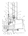
- the designated 1 device is used for the metered promotion of pourable and pourable goods and consists essentially of a arranged in a housing 3 drivable screw conveyor 2, by means of which the material to be conveyed is conveyed from a storage container, not shown, into a collecting container 10.
- the shaft 5 of the screw conveyor 2 is in this case suspended by means of a holder 4 in the housing 2, also this is provided with a viewing window 7 and a manually operable wiper blade 8.
- the screw conveyor 2 In order to accomplish an exact dosage of the material to be conveyed, the screw conveyor 2, a fan 11 downstream, which is separately driven by a pneumatic motor 12 in both directions of rotation.
- the pneumatic motor 12 is supplied via pressure lines 13 and 14 compressed air, to return the compressed air is a return line 15, which is equipped with a muffler 19 is provided.
- a control valve 16 and 17 or 18 are used for continuously adjusting the speed in the pressure lines 13 and 14 and the return lines 15.
- the conveying device 1 is further associated with a computing unit 21, which is connected via a signal line 22 with a weighing device 20 inserted into the collecting container 10 and via a signal line 23 with the drive motor of the screw conveyor 2, not shown.
- the arithmetic unit 21 is connected via signal lines 24, 25 and 26 to the control valves 16, 17 and 18.
- the fan 11 is driven by the pneumatic motor 12 in both directions of rotation. If the fan 11 is driven in the direction of rotation of the screw conveyor 2, then supports their funding. In a drive counter to the direction of rotation of the screw conveyor 2, however, their capacity is counteracted.
- the direction of rotation of the fan 11 against the conveying direction of the screw conveyor 2 is selected when a signal of the arithmetic unit 21 is fed by means of the weighing device 20 via the signal line 22, from which it follows that a selectable amount of the conveyed material is located in the collecting container 10.
- a discharge star 6 is arranged, which is driven together with the screw conveyor 3 and prevents thickening from forming in the conveyed material. Furthermore, the ventilator 11 is assigned a deflector plate 31, through which the conveyed material is directed into the collecting container 10.
- the pneumatic motor 12 and with this the fan 11 is suspended by means of an adjustable holder 32 on the housing 2.
- the holder 32 in this case consists of an angle piece 33 and a carrier 34, which are connected to each other by means of a screw 36. Since the screw 36 a machined into the elbow 33 slot 38 as well as a screw 35, with the angle 33 is fixed to the housing 2, pass through a slot 37, the pneumatic motor 11 can be adjusted both in height and in the axial direction. Thereby, the gap between the housing 3 and the fan 11 as well as the distance between the fan 11 and the Austragsstern 6 can be adjusted so that easy adjustments to the respective promoted Good are made.
Landscapes
- Engineering & Computer Science (AREA)
- Mechanical Engineering (AREA)
- Screw Conveyors (AREA)
- Filling Or Emptying Of Bunkers, Hoppers, And Tanks (AREA)
- Liquid Crystal (AREA)
- Formation And Processing Of Food Products (AREA)
- Non-Silver Salt Photosensitive Materials And Non-Silver Salt Photography (AREA)
- Iron Core Of Rotating Electric Machines (AREA)
- Branching, Merging, And Special Transfer Between Conveyors (AREA)
Abstract
Description
- Die Erfindung bezieht sich auf eine Vorrichtung zur dosierten Förderung von schütt- und rieselfähigen Gütern mittels einer in einem Gehäuse angeordneten antreibbaren Förderschnecke, deren Antrieb in Abhängigkeit von der Menge des geförderten Gutes steuerbar ist.
- Bei derartigen Fördervorrichtungen wird die Mengenregelung mittels eines Absperrschiebers bewerkstelligt, der der Förderschnecke nachgeschaltet ist und nach Erreichen einer wählbaren Menge des geförderten Gutes, die beispielsweise durch Wiegen bestimmbar ist, in das Gehäuse eingefahren wird. An dem Absperrschieber und dessen Führungen lagern sich aber oftmals Staub und auch das geförderte Gut ab, so dass Störungen, die zu Betriebsunterbrechungen führen können, unumgänglich sind. Vor allem aber ist bei dieser Ausgestaltung von Nachteil, dass mit Hilfe eines Absperrschiebers eine Feindosierung nur bedingt möglich ist, da dieser nicht kurzfristig in die Endstellung zu verfahren ist und die Förderschnecke jedoch einen Nachlauf aufweist. Ein unerwünschtes und unkontrolliertes Nachfließen des geförderten Gutes, durch das die abzugebende Menge ungünstig beeinflusst wird, ist demnach unumgänglich.
- Aufgabe der Erfindung ist es daher, die Fördervorrichtung der vorgenannten Art in der Weise auszustatten, dass ein Nachfließen des geförderten Gutes zuverlässig verhindert wird, so dass eine exakte dosierte Abgabe ermöglicht ist. Der Bauaufwand, mittels dem dies ermöglicht wird, soll gering gehalten werden, auch sollen Betriebsstörungen und dadurch bedingte Betriebsunterbrechungen nahezu ausgeschlossen sein. Des Weiteren soll eine Anpassung der Fördervorrichtung an das jeweils geförderte Gut ohne Schwierigkeiten ermöglicht und eine Klumpenbildung verhindert werden.
- Gemäß der Erfindung wird dies bei einer Fördervorrichtung der eingangs genannten Gattung dadurch erreicht, dass der Förderschnecke ein Ventilator nachgeschaltet ist der unabhängig von der Förderschnecke in zumindest der deren Förderrichtung entgegen gesetzter Drehrichtung antreibbar ist.
- Vorteilhaft ist es hierbei, den Ventilator durch einen vorzugsweise koaxial zu diesem angeordneten Pneumatikmotor anzutreiben.
- Der Pneumatikmotor sollte an eine Recheneinheit angeschlossen sein, die mit einer in einem der Förderschnecke zugeordneten Sammelraum eingesetzten Wiegeeinrichtung verbunden ist, und der Pneumatikmotor sollte in Abhängigkeit von den von der Wiegeeinrichtung abgegebenen Signalen entgegen der Förderrichtung der Förderschnecke gesteuert antreibbar sein, wobei der vorzugsweise am Sammelbehälter aufgehängte Pneumatikmotor mittels der Recheneinheit auch gesteuert in Förderrichtung der Förderschnecke antreibbar sein sollte.
- Zweckmäßig ist es ferner, den Pneumatikmotor mit einer vorzugsweise mit einem Schalldämpfer versehenen Abluftleitung auszustatten und im Übergangsbereich zwischen dem die Förderschnecke umgebenden Gehäuse und dem Sammelraum anzuordnen.
- Anstelle des Pneumatikmotors kann selbstverständlich auch ein andersartiges Antriebsaggregat, z.B. ein Elektro- oder ein Hydraulikmotor, zum Antrieb des Ventilators verwendet werden.
- Angezeigt ist es auch, dem Ventilator eine Abweisplatte zuzuordnen, die zwischen diesem und dem Pneumatikmotor, in den Sammelraum ragend, vorzugsweise auswechselbar eingebaut und die an dem Gehäuse der Förderschnecke und/oder einem Abschlussdeckel des Sammelraumes befestigt sein sollte, wobei der Pneumatikmotor die Abweisplatte durchgreift.
- Nach einer Weiterbildung ist vorgesehen, zwischen dem Ventilator und der Förderschnecke einen mit dieser trieblich verbundenen Austragstern anzuordnen und die Spaltbreite zwischen dem Ventilator und dem Gehäuse der Förderschnecke im vertikal unteren Bereich und/oder zwischen dem Ventilator und dem Austragstern einstellbar auszubilden.
- Wird eine Fördervorrichtung gemäß der Erfindung gestaltet , so ist es möglich, unmittelbar nach Erreichen einer bestimmten geförderten Menge nicht nur die Förderschnecke still zu setzen, sondern auch ein Nachfließen des geförderten Gutes zu verhindern. Wird nämlich der Ventilator entgegen der Drehrichtung der Förderschnecke in Gang gesetzt, so wird das nachfließende Gut durch den entstehenden Luftstrom beaufschlagt und je nach Fördergut auch mechanisch durch den Ventilator in dem Gehäuse der Förderschnecke zurückgehalten, so dass eine sofortige Förderunterbrechung gewährleistet ist. Auf diese Weise ist eine Feindosierung des geförderten Gutes zu bewerkstelligen, denn die in dem Sammelbehälter befindliche Menge wird durch unerwünschte Zugaben nicht beeinflusst.
- Der Bauaufwand, mittels dem dies zu erreichen ist, ist gering, da lediglich der Förderschnecke ein vorzugsweise durch einen Luftmotor antreibbarer Ventilator nachzuschalten ist. Ein vielseitiger Einsatz ist somit gegeben, da durch den zweckmäßigerweise in beiden Drehrichtungen antreibbaren Ventilator gegebenenfalls zusammen mit dem Austragsstern einer Klumpenbildung in dem zu fördernden Gut entgegengewirkt wird. Außerdem sind die Drehzahl des Ventilators, dessen Spaltabstände zu den zugeordneten Bauteilen sowie die Abweisplatte an das jeweils geförderte Gut ohne Schwierigkeiten anpassbar, eine sehr vielseitige vorteilhafte Verwendbarkeit der vorschlagsgemäß ausgebildeten Fördervorrichtung ist demnach gegeben.
- In der Zeichnung ist ein Ausführungsbeispiel einer gemäß der Erfindung ausgebildeten Fördervorrichtung dargestellt, das nachfolgend im Einzelnen erläutert ist.
- Die mit 1 bezeichnete Vorrichtung dient zur dosierten Förderung von schütt- und rieselfähigen Gütern und besteht im Wesentlichen aus einer in einem Gehäuse 3 angeordneten antreibbaren Förderschnecke 2, mittels der das zu fördernde Gut aus einem nicht dargestellten Vorratsbehälter in einen Sammelbehälter 10 gefördert wird. Die Welle 5 der Förderschnecke 2 ist hierbei mittels einer Halterung 4 in dem Gehäuse 2 aufgehängt, außerdem ist dieses mit einem Sichtfenster 7 und einem manuell bedienbaren Wischerblatt 8 versehen.
- Um eine exakte Dosierung des zu fördernden Gutes bewerkstelligen zu können, ist der Förderschnecke 2 ein Ventilator 11 nachgeschaltet, der durch einen Pneumatikmotor 12 in beiden Drehrichtungen gesondert antreibbar ist. Dazu wird dem Pneumatikmotor 12 über Druckleitungen 13 und 14 Druckluft zugeführt, zur Rückführung der Druckluft ist eine Rückleitung 15, die mit einem Schalldämpfer 19 ausgestattet ist, vorgesehen. Zur gesteuerten Druckluftzufuhr bzw. -rückführung sind in die Druckleitungen 13 und 14 sowie die Rückleitungen 15 jeweils ein Steuerventil 16 und 17 bzw. 18 zur stufenlosen Einstellung der Drehzahl eingesetzt.
- Der Fördervorrichtung 1 ist des Weiteren eine Recheneinheit 21 zugeordnet, die über eine Signalleitung 22 mit einer in den Sammelbehälter 10 eingesetzten Wiegeeinrichtung 20 sowie über eine Signalleitung 23 mit dem nicht gezeigten Antriebsmotor der Förderschnecke 2 verbunden ist. Außerdem ist die Recheneinheit 21 über Signalleitungen 24, 25 und 26 an die Steuerventile 16, 17 und 18 angeschlossen.
- Der Ventilator 11 ist durch den Pneumatikmotor 12 in beiden Drehrichtungen antreibbar. Wird der Ventilator 11 in der Drehrichtung der Förderschnecke 2 angetrieben, so wird deren Förderleistung unterstützt. Bei einem Antrieb entgegen der Drehrichtung der Förderschnecke 2 wird jedoch deren Förderleistung entgegengewirkt. Die Drehrichtung des Ventilators 11 entgegen der Förderrichtung der Förderschnecke 2 wird gewählt, wenn mittels der Wiegevorrichtung 20 über die Signalleitung 22 ein Signal der Recheneinheit 21 zugeleitet wird, aus dem sich ergibt, dass eine wählbare Menge des geförderten Gutes sich in dem Sammelbehälter 10 befindet. In diesem Betriebszustand wird über die Recheneinheit 21 zwar der Antriebsmotor der Förderschnecke 2 stillgesetzt, die Förderschnecke 2 weist aber in Abhängigkeit von dem geförderten Gut einen mehr oder weiniger großen Nachlauf auf, so dass die in dem Sammelbehälter 10 befindliche Menge überschritten würde. Durch den Ventilator 11 wird aber zuverlässig ein Nachlauf verhindert, denn durch den Ventilator 11, der bei einem Abschalten der Förderschnecke 2 entgegengesetzt zu deren Drehrichtung angetrieben wird, wird ein eventueller Nachlauf unterbunden.
- Zwischen der Förderschnecke 2 und dem Ventilator 11 ist ein Austragsstern 6 angeordnet, der zusammen mit der Förderschnecke 3 angetrieben wird und verhindert, dass sich in dem geförderten Gut Verdickungen bilden. Des Weiteren ist dem Ventilator 11 eine Abweisplatte 31 zugeordnet, durch die das geförderte Gut in den Sammelbehälter 10 geleitet wird.
- Der Pneumatikmotor 12 und mit diesem ist der Ventilator 11 mittels einer verstellbaren Halterung 32 an dem Gehäuse 2 aufgehängt. Die Halterung 32 besteht hierbei aus einem Winkelstück 33 und einem Träger 34, die mittels einer Schraube 36 miteinander verbunden sind. Da die Schraube 36 ein in das Winkelstück 33 eingearbeitetes Langloch 38 wie auch eine Schraube 35, mit der das Winkelstück 33 an dem Gehäuse 2 befestigt ist, ein Langloch 37 durchgreifen, kann der Pneumatikmotor 11 sowohl in der Höhe als auch in Achsrichtung verstellt werden. Dadurch können der Spalt zwischen dem Gehäuse 3 und dem Ventilator 11 wie auch der Abstand zwischen dem Ventilator 11 und dem Austragsstern 6 eingestellt werden, so dass leicht Anpassungen an das jeweils geförderte Gut vorzunehmen sind.
- Mit Hilfe des Ventilators 11 ist es somit, trotz des durch die Förderschnecke 2 durch deren Nachlauf bedingter Unwägbarkeiten möglich, eine Förderung sofort zu unterbinden, so dass eine exakte Dosierung des geförderten Gutes zu bewerkstelligen ist.
Claims (10)
- Vorrichtung (1) zur dosierten Förderung von schütt- und rieselfähigen Gütern mittels einer in einem Gehäuse (3) angeordneten antreibbaren Förderschnecke (2), deren Antrieb in Abhängigkeit von der Menge des geförderten Gutes steuerbar ist.
dadurch gekennzeichnet,
dass der Förderschnecke (2) ein Ventilator (11) nachgeschaltet ist, der unabhängig von der Förderschnecke (2) in zumindest der deren Förderrichtung entgegengesetzter Drehrichtung antreibbar ist. - Förder-Vorrichtung nach Anspruch 1,
dadurch gekennzeichnet,
dass der Ventilator (11) durch einen vorzugsweise koaxial zu diesem angeordneten Pneumatikmotor (12) antreibbar ist. - Förder-Vorrichtung nach Anspruch 2,
dadurch gekennzeichnet,
dass der Pneumatikmotor (11) an eine Recheneinheit (21) angeschlossen ist, die mit einer in einem der Förderschnecke (2) zugeordneten Sammelraum (10) angeordneten Wiegeeinrichtung (20) verbunden ist, und dass der Pneumatikmotor (12) in Abhängigkeit von den von der Wiegeeinrichtung (20) abgegebenen Signalen entgegen der Förderrichtung der Förderschnecke (2) gesteuert antreibbar ist. - Förder-Vorrichtung nach Anspruch 2 oder 3,
dadurch gekennzeichnet,
dass der vorzugsweise am Gehäuse (3) der Förderschnecke (2) aufgehängte Pneumatikmotor (12) mittels der Recheneinheit (21) zusätzlich gesteuert in Förderrichtung der Förderschnecke (2) antreibbar ist. - Förder-Vorrichtung nach einem oder mehreren der Ansprüche 2 bis 4,
dadurch gekennzeichnet,
dass der Pneumatikmotor (12) mit einer vorzugsweise mit einem Schalldämpfer (19) versehenen Abluftleitung (15) versehen ist. - Förder-Vorrichtung nach einem oder mehreren der Ansprüche 1 bis 5
dadurch gekennzeichnet,
dass der Ventilator (11) im Übergangsbereich zwischen dem die Förderschnecke (2) umgebenden Gehäuse (3) und dem Sammelraum (10) angeordnet ist. - Förder-Vorrichtung nach einem oder mehreren der Ansprüche 1 bis 6,
dadurch gekennzeichnet,
dass dem Ventilator (11) eine Abweisplatte (31) zugeordnet ist, die zwischen diesem und dem Pneumatikmotor (12), in den Sammelraum (10) ragend, vorzugsweise auswechselbar, eingesetzt ist. - Förder-Vorrichtung nach Anspruch 7,
dadurch gekennzeichnet,
dass die Abweisplatte (31) an dem Gehäuse (3) der Förderschnecke (2) und/oder einem Abschlussdeckel des Sammelraumes(10) befestigt ist und dass der Pneumatikmotor (12) die Abweisplatte (31) durchgreift. - Förder-Vorrichtung nach einem oder mehreren der Ansprüche 1 bis 8,
dadurch gekennzeichnet,
dass zwischen dem Ventilator (11) und der Förderschnecke (2) ein mit dieser trieblich verbundener Austragstern (6) angeordnet ist. - Vorrichtung nach Anspruch 9,
dadurch gekennzeichnet,
dass die Spaltbreiten zwischen dem Ventilator (11) und dem Gehäuse (2) der Förderschnecke (1) im vertikal unteren Bereich und/oder zwischen dem Ventilator (11) und dem Austragstern (6) einstellbar sind.
Priority Applications (1)
| Application Number | Priority Date | Filing Date | Title |
|---|---|---|---|
| PL08008333T PL1997752T3 (pl) | 2007-06-01 | 2008-05-02 | Przenośnik |
Applications Claiming Priority (1)
| Application Number | Priority Date | Filing Date | Title |
|---|---|---|---|
| DE202007007794U DE202007007794U1 (de) | 2007-06-01 | 2007-06-01 | Fördervorrichtung |
Publications (2)
| Publication Number | Publication Date |
|---|---|
| EP1997752A1 true EP1997752A1 (de) | 2008-12-03 |
| EP1997752B1 EP1997752B1 (de) | 2010-03-03 |
Family
ID=39731156
Family Applications (1)
| Application Number | Title | Priority Date | Filing Date |
|---|---|---|---|
| EP08008333A Not-in-force EP1997752B1 (de) | 2007-06-01 | 2008-05-02 | Fördervorrichtung |
Country Status (5)
| Country | Link |
|---|---|
| EP (1) | EP1997752B1 (de) |
| AT (1) | ATE459563T1 (de) |
| DE (2) | DE202007007794U1 (de) |
| ES (1) | ES2342442T3 (de) |
| PL (1) | PL1997752T3 (de) |
Citations (1)
| Publication number | Priority date | Publication date | Assignee | Title |
|---|---|---|---|---|
| DE19905313A1 (de) * | 1999-02-09 | 2000-08-17 | Ytong Ag | Vorrichtung und Verfahren zum Dosieren von schüttfähigem, insbesondere pulverförmigem Material |
-
2007
- 2007-06-01 DE DE202007007794U patent/DE202007007794U1/de not_active Expired - Lifetime
-
2008
- 2008-05-02 EP EP08008333A patent/EP1997752B1/de not_active Not-in-force
- 2008-05-02 DE DE502008000408T patent/DE502008000408D1/de active Active
- 2008-05-02 AT AT08008333T patent/ATE459563T1/de active
- 2008-05-02 ES ES08008333T patent/ES2342442T3/es active Active
- 2008-05-02 PL PL08008333T patent/PL1997752T3/pl unknown
Patent Citations (1)
| Publication number | Priority date | Publication date | Assignee | Title |
|---|---|---|---|---|
| DE19905313A1 (de) * | 1999-02-09 | 2000-08-17 | Ytong Ag | Vorrichtung und Verfahren zum Dosieren von schüttfähigem, insbesondere pulverförmigem Material |
Also Published As
| Publication number | Publication date |
|---|---|
| ES2342442T3 (es) | 2010-07-06 |
| EP1997752B1 (de) | 2010-03-03 |
| DE202007007794U1 (de) | 2008-10-09 |
| DE502008000408D1 (de) | 2010-04-15 |
| PL1997752T3 (pl) | 2010-09-30 |
| ATE459563T1 (de) | 2010-03-15 |
Similar Documents
| Publication | Publication Date | Title |
|---|---|---|
| EP1958899B1 (de) | Vorrichtung zum Fördern von Fluid | |
| AT516916A2 (de) | Pneumatische Förderereinrichtung und Dosieranlage sowie Sandungsanlage mit einer Strahlpumpe für rieselfähiges Gut | |
| EP1961288A1 (de) | Vorrichtung zur Einstellung der Position des Nachbeschleunigungsorgans in einer landwirtschaftlichen Erntemaschine | |
| EP0271828A2 (de) | Walzwerk und Verfahren zum Zuführen von körnigem Gut | |
| EP3352961A1 (de) | Vorrichtung und verfahren zur verarbeitung von thermoplastischem kunststoff mit einer blasvorrichtung für eine transportschnecke | |
| DE2462414A1 (de) | Walzenstuhl mit einer mit einem schuett-trichter versehenen speiseeinrichtung | |
| EP0629451A1 (de) | Pulverfördereinrichtung | |
| DE2543379A1 (de) | Vorrichtung zur kontinuierlichen herstellung von angemachtem moertel | |
| DE29618748U1 (de) | Vorrichtung zum Mahlen von teilchenförmigem Aufgabegut | |
| EP1997752B1 (de) | Fördervorrichtung | |
| EP1730059B1 (de) | Vorrichtung und verfahren zur pneumatischen förderung von fe inteiligen schü ttgütern | |
| EP0357929A2 (de) | Verfahren und Vorrichtung zum Dosieren von flüssigen Erstarrungsbeschleunigern zum Austragen von Spritzbeton | |
| EP2177461B1 (de) | Materialverteilervorrichtung | |
| DE4400029C2 (de) | Vorrichtung für eine regelbare dosierte Förderung von staub- und granulatförmigen Schüttgütern, bei konstantem Druck | |
| DE2853106A1 (de) | Anlage zur pneumatischen druckkesselfoerderung hydraulischer baustoffe im berg- und tunnelbau | |
| DE20100783U1 (de) | Vorrichtung zum Dosieren und Fördern von Schüttgütern | |
| DE19755733B4 (de) | Verfahren zum hydraulischen Fördern eines Schüttgutes | |
| DE10335583B4 (de) | Ladeeinrichtung für landwirtschaftliche Erntemaschine | |
| DE2146121A1 (de) | Blasluftsteuerung für Bogenanleger | |
| DE2523374A1 (de) | Vorrichtung zur kontinuierlichen herstellung von angemachtem moertel | |
| EP1172314B1 (de) | Druckluftfördergerät für Schüttgüter | |
| EP2848883B1 (de) | Bandtrocknungsanlage mit einem Trockenband | |
| CH425561A (de) | Spritzapparatur zum Aufbringen von dickflüssigem Spritzgut auf eine Unterlage | |
| AT326048B (de) | Vorrichtung zum gleichmässigen beschicken von fördergeblasen, insbesondere für silofräseinrichtungen | |
| DE102023116471A1 (de) | Pneumatische Verteilmaschine zum Ausbringen von Verteilgut und Verfahren zur Überwachung deren Betriebs |
Legal Events
| Date | Code | Title | Description |
|---|---|---|---|
| PUAI | Public reference made under article 153(3) epc to a published international application that has entered the european phase |
Free format text: ORIGINAL CODE: 0009012 |
|
| AK | Designated contracting states |
Kind code of ref document: A1 Designated state(s): AT BE BG CH CY CZ DE DK EE ES FI FR GB GR HR HU IE IS IT LI LT LU LV MC MT NL NO PL PT RO SE SI SK TR |
|
| AX | Request for extension of the european patent |
Extension state: AL BA MK RS |
|
| 17P | Request for examination filed |
Effective date: 20090520 |
|
| GRAP | Despatch of communication of intention to grant a patent |
Free format text: ORIGINAL CODE: EPIDOSNIGR1 |
|
| AKX | Designation fees paid |
Designated state(s): AT BE BG CH CY CZ DE DK EE ES FI FR GB GR HR HU IE IS IT LI LT LU LV MC MT NL NO PL PT RO SE SI SK TR |
|
| GRAS | Grant fee paid |
Free format text: ORIGINAL CODE: EPIDOSNIGR3 |
|
| GRAA | (expected) grant |
Free format text: ORIGINAL CODE: 0009210 |
|
| AK | Designated contracting states |
Kind code of ref document: B1 Designated state(s): AT BE BG CH CY CZ DE DK EE ES FI FR GB GR HR HU IE IS IT LI LT LU LV MC MT NL NO PL PT RO SE SI SK TR |
|
| REG | Reference to a national code |
Ref country code: GB Ref legal event code: FG4D Free format text: NOT ENGLISH |
|
| REG | Reference to a national code |
Ref country code: CH Ref legal event code: EP |
|
| REG | Reference to a national code |
Ref country code: IE Ref legal event code: FG4D |
|
| REF | Corresponds to: |
Ref document number: 502008000408 Country of ref document: DE Date of ref document: 20100415 Kind code of ref document: P |
|
| REG | Reference to a national code |
Ref country code: NL Ref legal event code: T3 |
|
| REG | Reference to a national code |
Ref country code: ES Ref legal event code: FG2A Ref document number: 2342442 Country of ref document: ES Kind code of ref document: T3 |
|
| PG25 | Lapsed in a contracting state [announced via postgrant information from national office to epo] |
Ref country code: NO Free format text: LAPSE BECAUSE OF FAILURE TO SUBMIT A TRANSLATION OF THE DESCRIPTION OR TO PAY THE FEE WITHIN THE PRESCRIBED TIME-LIMIT Effective date: 20100603 Ref country code: LT Free format text: LAPSE BECAUSE OF FAILURE TO SUBMIT A TRANSLATION OF THE DESCRIPTION OR TO PAY THE FEE WITHIN THE PRESCRIBED TIME-LIMIT Effective date: 20100303 Ref country code: HR Free format text: LAPSE BECAUSE OF FAILURE TO SUBMIT A TRANSLATION OF THE DESCRIPTION OR TO PAY THE FEE WITHIN THE PRESCRIBED TIME-LIMIT Effective date: 20100303 |
|
| LTIE | Lt: invalidation of european patent or patent extension |
Effective date: 20100303 |
|
| PG25 | Lapsed in a contracting state [announced via postgrant information from national office to epo] |
Ref country code: SI Free format text: LAPSE BECAUSE OF FAILURE TO SUBMIT A TRANSLATION OF THE DESCRIPTION OR TO PAY THE FEE WITHIN THE PRESCRIBED TIME-LIMIT Effective date: 20100303 Ref country code: FI Free format text: LAPSE BECAUSE OF FAILURE TO SUBMIT A TRANSLATION OF THE DESCRIPTION OR TO PAY THE FEE WITHIN THE PRESCRIBED TIME-LIMIT Effective date: 20100303 Ref country code: LV Free format text: LAPSE BECAUSE OF FAILURE TO SUBMIT A TRANSLATION OF THE DESCRIPTION OR TO PAY THE FEE WITHIN THE PRESCRIBED TIME-LIMIT Effective date: 20100303 |
|
| REG | Reference to a national code |
Ref country code: IE Ref legal event code: FD4D |
|
| REG | Reference to a national code |
Ref country code: PL Ref legal event code: T3 |
|
| PG25 | Lapsed in a contracting state [announced via postgrant information from national office to epo] |
Ref country code: GR Free format text: LAPSE BECAUSE OF FAILURE TO SUBMIT A TRANSLATION OF THE DESCRIPTION OR TO PAY THE FEE WITHIN THE PRESCRIBED TIME-LIMIT Effective date: 20100604 Ref country code: EE Free format text: LAPSE BECAUSE OF FAILURE TO SUBMIT A TRANSLATION OF THE DESCRIPTION OR TO PAY THE FEE WITHIN THE PRESCRIBED TIME-LIMIT Effective date: 20100303 Ref country code: CY Free format text: LAPSE BECAUSE OF FAILURE TO SUBMIT A TRANSLATION OF THE DESCRIPTION OR TO PAY THE FEE WITHIN THE PRESCRIBED TIME-LIMIT Effective date: 20100303 Ref country code: SE Free format text: LAPSE BECAUSE OF FAILURE TO SUBMIT A TRANSLATION OF THE DESCRIPTION OR TO PAY THE FEE WITHIN THE PRESCRIBED TIME-LIMIT Effective date: 20100303 Ref country code: RO Free format text: LAPSE BECAUSE OF FAILURE TO SUBMIT A TRANSLATION OF THE DESCRIPTION OR TO PAY THE FEE WITHIN THE PRESCRIBED TIME-LIMIT Effective date: 20100303 Ref country code: IE Free format text: LAPSE BECAUSE OF FAILURE TO SUBMIT A TRANSLATION OF THE DESCRIPTION OR TO PAY THE FEE WITHIN THE PRESCRIBED TIME-LIMIT Effective date: 20100303 |
|
| BERE | Be: lapsed |
Owner name: NOLD, WERNER Effective date: 20100531 |
|
| PG25 | Lapsed in a contracting state [announced via postgrant information from national office to epo] |
Ref country code: SK Free format text: LAPSE BECAUSE OF FAILURE TO SUBMIT A TRANSLATION OF THE DESCRIPTION OR TO PAY THE FEE WITHIN THE PRESCRIBED TIME-LIMIT Effective date: 20100303 Ref country code: IS Free format text: LAPSE BECAUSE OF FAILURE TO SUBMIT A TRANSLATION OF THE DESCRIPTION OR TO PAY THE FEE WITHIN THE PRESCRIBED TIME-LIMIT Effective date: 20100703 Ref country code: BG Free format text: LAPSE BECAUSE OF FAILURE TO SUBMIT A TRANSLATION OF THE DESCRIPTION OR TO PAY THE FEE WITHIN THE PRESCRIBED TIME-LIMIT Effective date: 20100603 |
|
| PG25 | Lapsed in a contracting state [announced via postgrant information from national office to epo] |
Ref country code: MC Free format text: LAPSE BECAUSE OF NON-PAYMENT OF DUE FEES Effective date: 20100531 |
|
| PLBE | No opposition filed within time limit |
Free format text: ORIGINAL CODE: 0009261 |
|
| STAA | Information on the status of an ep patent application or granted ep patent |
Free format text: STATUS: NO OPPOSITION FILED WITHIN TIME LIMIT |
|
| PG25 | Lapsed in a contracting state [announced via postgrant information from national office to epo] |
Ref country code: DK Free format text: LAPSE BECAUSE OF FAILURE TO SUBMIT A TRANSLATION OF THE DESCRIPTION OR TO PAY THE FEE WITHIN THE PRESCRIBED TIME-LIMIT Effective date: 20100303 |
|
| 26N | No opposition filed |
Effective date: 20101206 |
|
| PG25 | Lapsed in a contracting state [announced via postgrant information from national office to epo] |
Ref country code: BE Free format text: LAPSE BECAUSE OF NON-PAYMENT OF DUE FEES Effective date: 20100531 |
|
| PG25 | Lapsed in a contracting state [announced via postgrant information from national office to epo] |
Ref country code: MT Free format text: LAPSE BECAUSE OF FAILURE TO SUBMIT A TRANSLATION OF THE DESCRIPTION OR TO PAY THE FEE WITHIN THE PRESCRIBED TIME-LIMIT Effective date: 20100303 |
|
| PG25 | Lapsed in a contracting state [announced via postgrant information from national office to epo] |
Ref country code: HU Free format text: LAPSE BECAUSE OF FAILURE TO SUBMIT A TRANSLATION OF THE DESCRIPTION OR TO PAY THE FEE WITHIN THE PRESCRIBED TIME-LIMIT Effective date: 20100904 Ref country code: LU Free format text: LAPSE BECAUSE OF NON-PAYMENT OF DUE FEES Effective date: 20100502 Ref country code: PT Free format text: LAPSE BECAUSE OF FAILURE TO SUBMIT A TRANSLATION OF THE DESCRIPTION OR TO PAY THE FEE WITHIN THE PRESCRIBED TIME-LIMIT Effective date: 20100803 |
|
| PG25 | Lapsed in a contracting state [announced via postgrant information from national office to epo] |
Ref country code: TR Free format text: LAPSE BECAUSE OF FAILURE TO SUBMIT A TRANSLATION OF THE DESCRIPTION OR TO PAY THE FEE WITHIN THE PRESCRIBED TIME-LIMIT Effective date: 20100303 |
|
| REG | Reference to a national code |
Ref country code: AT Ref legal event code: MM01 Ref document number: 459563 Country of ref document: AT Kind code of ref document: T Effective date: 20130502 |
|
| PG25 | Lapsed in a contracting state [announced via postgrant information from national office to epo] |
Ref country code: AT Free format text: LAPSE BECAUSE OF NON-PAYMENT OF DUE FEES Effective date: 20130502 |
|
| REG | Reference to a national code |
Ref country code: FR Ref legal event code: PLFP Year of fee payment: 8 |
|
| PGFP | Annual fee paid to national office [announced via postgrant information from national office to epo] |
Ref country code: ES Payment date: 20150520 Year of fee payment: 8 Ref country code: CZ Payment date: 20150522 Year of fee payment: 8 Ref country code: GB Payment date: 20150521 Year of fee payment: 8 |
|
| PGFP | Annual fee paid to national office [announced via postgrant information from national office to epo] |
Ref country code: NL Payment date: 20150520 Year of fee payment: 8 Ref country code: IT Payment date: 20150528 Year of fee payment: 8 Ref country code: PL Payment date: 20150429 Year of fee payment: 8 Ref country code: FR Payment date: 20150528 Year of fee payment: 8 |
|
| PGFP | Annual fee paid to national office [announced via postgrant information from national office to epo] |
Ref country code: CH Payment date: 20150813 Year of fee payment: 8 |
|
| REG | Reference to a national code |
Ref country code: CH Ref legal event code: PL |
|
| REG | Reference to a national code |
Ref country code: NL Ref legal event code: MM Effective date: 20160601 |
|
| GBPC | Gb: european patent ceased through non-payment of renewal fee |
Effective date: 20160502 |
|
| PG25 | Lapsed in a contracting state [announced via postgrant information from national office to epo] |
Ref country code: CZ Free format text: LAPSE BECAUSE OF NON-PAYMENT OF DUE FEES Effective date: 20160502 Ref country code: LI Free format text: LAPSE BECAUSE OF NON-PAYMENT OF DUE FEES Effective date: 20160531 Ref country code: CH Free format text: LAPSE BECAUSE OF NON-PAYMENT OF DUE FEES Effective date: 20160531 |
|
| PG25 | Lapsed in a contracting state [announced via postgrant information from national office to epo] |
Ref country code: NL Free format text: LAPSE BECAUSE OF NON-PAYMENT OF DUE FEES Effective date: 20160601 Ref country code: IT Free format text: LAPSE BECAUSE OF NON-PAYMENT OF DUE FEES Effective date: 20160502 |
|
| REG | Reference to a national code |
Ref country code: FR Ref legal event code: ST Effective date: 20170131 |
|
| PG25 | Lapsed in a contracting state [announced via postgrant information from national office to epo] |
Ref country code: FR Free format text: LAPSE BECAUSE OF NON-PAYMENT OF DUE FEES Effective date: 20160531 |
|
| PG25 | Lapsed in a contracting state [announced via postgrant information from national office to epo] |
Ref country code: GB Free format text: LAPSE BECAUSE OF NON-PAYMENT OF DUE FEES Effective date: 20160502 |
|
| PG25 | Lapsed in a contracting state [announced via postgrant information from national office to epo] |
Ref country code: PL Free format text: LAPSE BECAUSE OF NON-PAYMENT OF DUE FEES Effective date: 20160502 |
|
| PG25 | Lapsed in a contracting state [announced via postgrant information from national office to epo] |
Ref country code: ES Free format text: LAPSE BECAUSE OF NON-PAYMENT OF DUE FEES Effective date: 20160503 |
|
| REG | Reference to a national code |
Ref country code: ES Ref legal event code: FD2A Effective date: 20180625 |
|
| PGFP | Annual fee paid to national office [announced via postgrant information from national office to epo] |
Ref country code: DE Payment date: 20190704 Year of fee payment: 12 |
|
| REG | Reference to a national code |
Ref country code: DE Ref legal event code: R119 Ref document number: 502008000408 Country of ref document: DE |
|
| PG25 | Lapsed in a contracting state [announced via postgrant information from national office to epo] |
Ref country code: DE Free format text: LAPSE BECAUSE OF NON-PAYMENT OF DUE FEES Effective date: 20201201 |