EP1997674A1 - Tip-up type automotive seat - Google Patents
Tip-up type automotive seat Download PDFInfo
- Publication number
- EP1997674A1 EP1997674A1 EP06843784A EP06843784A EP1997674A1 EP 1997674 A1 EP1997674 A1 EP 1997674A1 EP 06843784 A EP06843784 A EP 06843784A EP 06843784 A EP06843784 A EP 06843784A EP 1997674 A1 EP1997674 A1 EP 1997674A1
- Authority
- EP
- European Patent Office
- Prior art keywords
- latch
- cam
- seat cushion
- seat
- cutout
- Prior art date
- Legal status (The legal status is an assumption and is not a legal conclusion. Google has not performed a legal analysis and makes no representation as to the accuracy of the status listed.)
- Granted
Links
- 230000005484 gravity Effects 0.000 claims abstract description 7
- 230000001154 acute effect Effects 0.000 claims abstract description 5
- 230000014509 gene expression Effects 0.000 description 2
- 230000000717 retained effect Effects 0.000 description 2
- 230000004048 modification Effects 0.000 description 1
- 238000012986 modification Methods 0.000 description 1
Images




Classifications
-
- B—PERFORMING OPERATIONS; TRANSPORTING
- B60—VEHICLES IN GENERAL
- B60N—SEATS SPECIALLY ADAPTED FOR VEHICLES; VEHICLE PASSENGER ACCOMMODATION NOT OTHERWISE PROVIDED FOR
- B60N2/00—Seats specially adapted for vehicles; Arrangement or mounting of seats in vehicles
- B60N2/24—Seats specially adapted for vehicles; Arrangement or mounting of seats in vehicles for particular purposes or particular vehicles
- B60N2/30—Non-dismountable or dismountable seats storable in a non-use position, e.g. foldable spare seats
- B60N2/3002—Non-dismountable or dismountable seats storable in a non-use position, e.g. foldable spare seats back-rest movements
- B60N2/3004—Non-dismountable or dismountable seats storable in a non-use position, e.g. foldable spare seats back-rest movements by rotation only
- B60N2/3009—Non-dismountable or dismountable seats storable in a non-use position, e.g. foldable spare seats back-rest movements by rotation only about transversal axis
- B60N2/3013—Non-dismountable or dismountable seats storable in a non-use position, e.g. foldable spare seats back-rest movements by rotation only about transversal axis the back-rest being hinged on the vehicle frame
-
- B—PERFORMING OPERATIONS; TRANSPORTING
- B60—VEHICLES IN GENERAL
- B60N—SEATS SPECIALLY ADAPTED FOR VEHICLES; VEHICLE PASSENGER ACCOMMODATION NOT OTHERWISE PROVIDED FOR
- B60N2/00—Seats specially adapted for vehicles; Arrangement or mounting of seats in vehicles
- B60N2/24—Seats specially adapted for vehicles; Arrangement or mounting of seats in vehicles for particular purposes or particular vehicles
- B60N2/30—Non-dismountable or dismountable seats storable in a non-use position, e.g. foldable spare seats
- B60N2/3038—Cushion movements
- B60N2/304—Cushion movements by rotation only
- B60N2/3045—Cushion movements by rotation only about transversal axis
- B60N2/3047—Cushion movements by rotation only about transversal axis the cushion being hinged at the back-rest
Definitions
- the present invention relates to a tip-up type automotive seat which includes a seat back and a seat cushion adapted to be capable of being tipped up from a used position, at which the seat cushion becomes a substantially horizontal posture, to a tipped-up position at which the seat back becomes opposed to the seat back in a substantially vertical posture.
- a tip-up type automotive seat in which a seat cushion of the automotive seat is allowed to be tipped up from a used position, at which the seat cushion becomes a substantially horizontal posture, to a tipped-up position at which the seat cushion becomes opposed to a seat back of the automotive seat in a substantially vertical posture, in order that a space on a portion of an automotive body floor which is located under the seat cushion when located in the used position can be used as a storage space for any baggage or luggage at the time of none-use of the automotive seat.
- This tip-up type automotive seat is provided with a tipping-up lock mechanism for releasably locking the seat cushion in the tipped-up position at which the seat cushion becomes opposed to the seat back, when the seat cushion is pivoted to the tipped-up position in one motion (Japanese Patent Application Laid-Open No. 2005-212554 ).
- any various baggage or luggage can be advantageously stored in the following manner. That is, for example, any longitudinal baggage or luggage is carried on the portion of the automotive body floor, whereas any small baggage or luggage can be stored in a space between the seat cushion locked in the middle position and the seat back in the substantially vertical posture.
- a tip-up type automotive seat comprising a seat back including a pair of first spaced apart side brackets, a seat cushion including a pair of second spaced apart side brackets, the second side brackets having upwardly curved rear portions, the second side brackets of the seat cushion being pivotally supported at the upward curved rear portions thereof to portions of the first side brackets of the seat back, which are adjacent lower end portions of the first side brackets of the seat back, by first support pins, whereby the seat cushion is allowed to be pivoted about the first support pins from a used position, at which the seat cushion becomes a substantially horizontal posture, to a tipped-up position at which the seat cushion becomes opposed to the seat back in a substantially vertical posture, the upwardly curved rear portions of the second side brackets being formed so as to have substantially semicircle-shaped edges extending around the first support pins, a tipping-up lock mechanism for selectively and releasably locking the seat cushion with respect to the seat back, in
- the lower portion of the cam is disengaged from the engaging step portion of the latch and slips into the recess portion of the latch which has the depth that is not less than the height of the engaged portion between the protruding tooth of the latch and each of the first, second, and third cutout teeth.
- the latch is swung up, whereby the protruding tooth of the latch is disengaged from any one of the first, second, and third cutout teeth.
- the angle of the cam relative to the latch is set in such a manner that the angle between the reference line connecting the axial center of the second support pin of the latch and the abutment point of the lower portion of the cam against the engaging step portion of the latch, and the line connecting the axial center of the third support pin of the cam and the abutment point is kept to be an acute angle, so that the cam functions as a prop with respect to the engaging step portion of the latch and the latch is held so as to be unable to be swung, so that even if a person unintentionally tries to lift the seat cushion up toward the middle position or the tipped-up position, the engagement between the protruding tooth and the first cutout tooth of the side bracket of the seat cushion is positively maintained.
- the lower portion of the cam may be formed into a substantially semiellipse-shape
- a bottom surface of the engaging step portion of the latch may be formed into a substantially J-shape
- the recess portion of the latch may be formed into a substantially U-shape having a depth larger than the height of the engaged portion between the protruding tooth of the latch and each of the first, second, and third cutout teeth.
- a tip-up type automotive seat which includes a seat cushion A and a seat back B.
- the seat cushion includes a pair of spaced apart side brackets 1 serving as side frame sections of a seat cushion frame for the seat cushion
- the seat back includes a pair of spaced apart side brackets 2 serving as side frame sections of a seat back frame for the seat back (only one side bracket 1 of the seat cushion and only one side bracket 2 of the seat back are shown in Fig. 2 ).
- the side brackets 1 of the seat cushion are pivotally supported at upwardly curved rear portions thereof to portions of the side brackets 2 of the seat back, which are adjacent lower end portions of the side brackets 2 of the seat back, by support pins 3, so that the seat cushion is allowed to be pivoted or tipped up around the support pins 3 from a used position, at which the seat cushion becomes a substantially horizontal posture, to a tipped-up position at which the seat cushion becomes opposed to the seat back in a substantially vertical posture.
- the tip-up type automotive seat is provided with a stand leg portion 4.
- the stand leg portion 4 is formed into a substantially U-shape in outline and pivotally supported at upper end regions of spaced apart vertical portions thereof to lower regions of forward portions of the side brackets of the seat cushion A by support pins 4a.
- a receiving base 4b for receiving and releasably engaging a lower horizontal portion of the stand leg portion 4 is mounted on a lower step portion f 1 of an automotive body floor F.
- the stand leg portion 4 is adapted to be releasably engaged at the lower horizontal portion thereof with the receiving base 4b so as to be obliquely stand up from the lower step portion f 1 of the automotive body floor F, whereby when the seat cushion is locked in the used position by a tipping-up lock mechanism for releasably locking the seat cushion with respect to the seat back and preventing the pivotal movement of the seat cushion, which will be discussed in detail hereinafter, the seat cushion is maintained in the substantially horizontal posture by the stand leg portion 4.
- the seat back are supported at the lower end portions of the side brackets thereof to a pair of spaced apart base brackets 5 mounted on an upper step portion f 2 of the automotive body floor F so as to stand up from the upper step portion f 2 .
- the tip-up type automotive seat according to the embodiment of the present invention is provided with the tipping-up lock mechanism.
- the tipping-up lock mechanism is provided on one of both sides of the automotive seat.
- the upwardly curved rear portions of the side brackets 1 of the seat cushion have substantially semicircle-shaped edges extending about the support pins 3 of the side brackets 1.
- the tipping-up lock mechanism includes first, second, and third spaced apart cutout teeth 6a, 6b, 6c which are provided at a substantially semicircle-shaped edge of one of the side brackets 1 of the seat cushion so as to be in turn arranged from a rearward direction of the substantially semicircle-shaped edge to a forward direction of the substantially semicircle-shaped edge. More particularly, the first cutout tooth 6a, the second cutout tooth 6b, and the third cutout tooth 6c are provided at a rearward region of the substantially semicircle-shaped edge, at a middle region of the substantially semicircle-shaped edge, and at a forward region of the substantially semicircle-shaped edge, respectively.
- the first cutout tooth 6a serves as means to facilitate causing of the seat cushion to be kept in the used position.
- the third cutout tooth 6c serves as means to facilitate causing of the seat cushion to be kept in the tipped-up position.
- the second cutout tooth 6b serves as means to facilitate causing of the seat cushion to be kept in a middle position between the used position and the tipped-up position.
- the tipping-up lock mechanism further includes a latch 7 and a cam 8.
- the latch 7 is pivotally supported at a forward portion 7a thereof to a corresponding side bracket 2 of the seat back by a support pin 70 so as to be swingable upward.
- the cam 8 includes a body and a lower portion 8a extending downward from the cam body.
- the cam 8 is swingably supported at a substantially middle portion thereof to the side bracket 2 of the seat back by a support pin 80 with the lower portion 8a being directed toward an upper region of a rearward potion 7b of the latch 7.
- the latch 7 is provided at a lower edge of the rearward portion 7b thereof with a protruding tooth 71 which is adapted to be selectively and releasably engaged with the first, second, and third cutout teeth 6a, 6b, 6c, whereby the seat cushion is selectively and releasably locked in the used position, in the middle position, and the tipped-up position.
- the protruding tooth 71 of the latch 7 can be securely engaged with the second and third cutout teeth 6b, 6c
- the protruding tooth 71 is configured to include two protruding tooth-portions which are spaced apart from each other in the forward/rearward direction.
- the first cutout tooth 6a is configured to have a recess portion which extends along a region of the substantially semicircle-shaped edge of the side bracket 1 and is adapted to receive the protruding tooth 71 of the latch 7 during the pivotal movement of the seat cushion to the used position from the middle position or the tipped-up position.
- the latch 7 includes an engaging step portion 72 against which the lower portion 8a of the cam 8 is abutted, and a recess portion 73 for allowing the cam 8 to be swung.
- the engaging step portion 72 and the recess portion 73 are formed in the upper region of the rearward portion 7b of the latch 7.
- the recess portion 73 of the latch 7 extends continuously from an edge of the engaging step portion 72 and is formed so as to have a depth which is not less than a height of an engaged portion between the protruding tooth 71 of the latch 7 and each of the first, second, and third cutout teeth 6a, 6b, 6c, in order that the protruding tooth 71 of the latch 7 can be escapingly disengaged from the cutout teeth 6a, 6b, 6c.
- an angle of the cam 8 relative to the latch 7 is set in such a manner that an angle ⁇ between a reference line L 1 connecting an axial center O 1 of the support pin 70 of the latch 7 and an abutment point P of the lower portion 8a of the cam 8 against the engaging step portion 72 ( Fig. 2 ), and a line L 2 connecting an axial center O 2 of the support pin 80 of the cam 8 and the abutment point P is kept to be an acute angle.
- the cam 8 functions as a prop with respect to the engaging step portion 72 of the latch 7, so that when the lower portion 8a of the cam 8 is abutted against the engaging step portion 72 of the latch 7, the engagement between the protruding tooth 71 of the latch 7 and the cutout tooth 6a, 6b or 6c of the side bracket 1 of the seat cushion can be positively maintained.
- a bottom surface of the engaging step portion 72 of the latch 7 is formed so as to be adjacent the protruding tooth 71 of the latch 7, so that the reference line L 1 is set so as to be descent rearward from the axial center O 1 of the support pin 70 of the latch 7.
- the lower portion 8a of the cam 8 is formed into a substantially semiellipse-shape.
- the bottom surface of the engaging step portion 72 of the latch 7 is formed into a substantially J-shape.
- the substantially J-shaped bottom surface of the engaging step portion 72 is formed so as to have a curve surface which allows at least half or more region of the lower portion 8a of the cam 8 to be received by the engaging step portion 72, so that the lower portion 8a of the cam 8 can be positively abutted against the engaging step portion 72 of the latch 7 and stably received by the engaging step portion 72.
- the recess portion 73 of the latch 7 may be formed into a substantially U-shape which has a depth larger than the height of the engaged portion between the protruding tooth 71 of the latch 7 and each of the first, second, and third cutout teeth 6a, 6b, 6c of the side bracket 1 of the seat cushion and which fits the lower portion 8a of the cam 8.
- the recess portion 73 of the latch 7 serves to allow the cam 8 to be swung up in such a manner that the lower portion 8a of the cam 8 slips into the recess portion 73 of the latch 7 while being disengaged from the engaging step portion 72.
- the latch 7 As the lower portion 8a of the cam 8 slips into the recess portion 73 of the latch 7, the latch 7 is swung up.
- the protruding tooth 71 of the latch 7 is positively disengaged from any one of the cutout teeth 6a, 6b, 6c of the side bracket 1 of the seat cushion.
- the cam 8 is formed into a substantially L-shape in outline.
- a wire 9 of a first wire cable which is inserted through a tube of the first wire cable is coupled at one end portion thereof to an upper end portion 8b of the cam body.
- the other end portion of the wire 9 is connected to an operating lever 10 (see Fig. 1 ).
- the operating lever 10 is swingably provided in a recess portion formed in a lower region of a forward section of the seat cushion A and is adapted to be pulled by a person.
- the tipping-up lock mechanism becomes unlocked as will be discussed in detail hereinafter. In the condition where the tipping-up lock mechanism is unlocked, the person can manually cause the seat cushion to be tipped up in one motion.
- the stand leg portion 4 is typically urged toward a stored position under the seat cushion by a tension spring 11 which is retained at one end thereof to an upper end region of one of the spaced apart vertical portions of the substantially U-shaped stand leg portion 4 which is located upward of a support pin 4a of the vertical portion, and retained at the other end thereof to a forward portion of the side bracket of the seat cushion.
- a wire of a second wire cable 12 which is inserted through a tube 12c of the second wire cable 12 is coupled at one end portion 12a thereof to the upper end region of the vertical portion of the substantially U-shaped stand leg portion 4 and coupled at the other end portion thereof (not shown) to the seat back.
- the other end portion 12b of the wire of the second wire cable 12 is supported to a retaining piece 13 which is provided at a suitable portion of the seat back frame.
- the other end portion 12b of the wire of the second wire cable 12 is provided with a spherical end stop 12d and penetrated through a slit of the retaining piece 13 so as to be movable relative to the retaining piece 13.
- the wire of the second wire cable 12 is in a condition shown in Fig. 5a .
- the wire of the second cable 12 is pulled against an action of the tension spring (as shown in Fig. 5b ) so as to allow the stand leg portion 4 to be pivoted toward a developed position until the seat cushion reaches the position just before the middle position.
- the action of the tension spring 11 ( Fig. 4 ) is exerted on the wire of the second wire cable 12, whereby the wire of the second wire cable 12 is moved in such a manner that the wire end portion 12b thereof is moved relative to the retaining piece 13 so as to project from the retaining piece 13 as shown in Fig. 5c .
- the stand leg portion 4 is moved to the stored position by the action of the tension spring 11. More particularly, the stand leg portion 4 can be pivoted toward the stored position synchronously with the tipping-up movement of the seat cushion and can be pivoted toward the developed position synchronously with returning of the seat cushion to the used position.
- any suitable conventional compensator (not shown) for compensating a pulling force exerted on the wire of the second cable wire 12 and adjusting a total length of the wire of the second wire cable 12 is provided at a suitable portion of the wire of the second wire cable 12.
- the latch 7 is swung upward in a counterclockwise direction about the support pin 70, whereby the protruding tooth 71 of the latch 7 is disengaged from the cutout tooth 6a (6b or 6c) as shown in Fig. 7 .
- the seat cushion is brought to an unlocked condition where it is released from the seat back.
- the recess portion 73 of the latch 7 is formed so as to have the depth which is not less than the height of the engaged portion between the protruding tooth 71 of the latch 7 and each of the cutout teeth 6a, 6b, 6c, so that when the lower portion 8a of the cam 8 slips into the recess portion 73 and the latch 7 is swung up, the protruding tooth 71 of the latch 7 can be positively disengaged from the cutout tooth 6a, 6b, or 6c.
- the protruding tooth 71 of the latch 7 is disengaged from the first cutout tooth 6a of the side bracket 1 of the seat cushion by operating the operating lever 10, and the seat cushion is to be locked in the middle position, the person lifts up the seat cushion with his/her hand while leaving the operating lever 10 pulled and can cause the seat cushion to be locked in the middle position as shown in Figs. 8 and 9 , by releasing his/her hand from the operating lever.
- the stand leg portion 4 is stored in the stored position.
- the seat cushion can withstand a load applied to the seat cushion by the baggage of luggage, since the seat cushion is locked with respect to the seat back by the tipping-up lock mechanism.
- the person causes the protruding tooth 71 of the latch 7 to be disengaged from the second cutout tooth 6b of the side bracket 1 by pull-operating the operating lever in the same manner as discussed above and can cause the seat cushion to be pivoted to the tipped-up position.
- the protruding tooth 71 of the latch 7 becomes operatively engaged with the third cutout tooth 6c of the side bracket 1 of the seat cushion as shown in Fig. 13 .
- the seat cushion is locked in the tipped-up position by the tipping-up lock mechanism.
- the person causes the protruding tooth 71 of the latch 7 to be disengaged from the third cutout tooth 6c of the side bracket 1 of the seat cushion by pull-operating the operating lever in the same manner as discussed above and can cause the seat cushion to be returned to the used position.
- the cam 8 and the latch 7 are returned to their original positions by gravity and the protruding tooth 71 of the latch 7 becomes operatively engaged with the first cutout tooth 6a of the side bracket 1 of the seat cushion.
- the seat cushion is locked in the used position by the tipping-up lock mechanism.
- the stand leg portion is pivoted and reaches the developed position at which the stand leg portion 4 is then operatively engaged with the receiving base 4b.
- a second tipping-up lock mechanism constructed in the same manner as the first tipping-up lock mechanism is done may be provided on the other side of the automotive seat.
- a cam of the second tipping-up lock mechanism is coupled to the operating lever 10 via a wire cable.
Landscapes
- Engineering & Computer Science (AREA)
- Aviation & Aerospace Engineering (AREA)
- Transportation (AREA)
- Mechanical Engineering (AREA)
- Seats For Vehicles (AREA)
Abstract
Description
- The present invention relates to a tip-up type automotive seat which includes a seat back and a seat cushion adapted to be capable of being tipped up from a used position, at which the seat cushion becomes a substantially horizontal posture, to a tipped-up position at which the seat back becomes opposed to the seat back in a substantially vertical posture.
- As an automotive seat, there is known a tip-up type automotive seat in which a seat cushion of the automotive seat is allowed to be tipped up from a used position, at which the seat cushion becomes a substantially horizontal posture, to a tipped-up position at which the seat cushion becomes opposed to a seat back of the automotive seat in a substantially vertical posture, in order that a space on a portion of an automotive body floor which is located under the seat cushion when located in the used position can be used as a storage space for any baggage or luggage at the time of none-use of the automotive seat. This tip-up type automotive seat is provided with a tipping-up lock mechanism for releasably locking the seat cushion in the tipped-up position at which the seat cushion becomes opposed to the seat back, when the seat cushion is pivoted to the tipped-up position in one motion (Japanese Patent Application Laid-Open No.
2005-212554 - If the seat cushion of such an automotive seat can be configured to be also locked in a middle position between the used position and the tipped-up position by the tipping-up lock mechanism, any various baggage or luggage can be advantageously stored in the following manner. That is, for example, any longitudinal baggage or luggage is carried on the portion of the automotive body floor, whereas any small baggage or luggage can be stored in a space between the seat cushion locked in the middle position and the seat back in the substantially vertical posture.
- It is an object of the present invention to provide a tip-up type automotive seat including a tipping-up lock mechanism which can cause a seat cushion of the automotive seat to be selectively and releasably locked in a used position, a tipped-up position, and a middle position between the used position and the tipped-up position, with reliability.
- It is another object of the present invention to provide a tip-up type automotive seat including a tipping-up lock mechanism which can cause a seat cushion of the automotive seat to be securely unlocked in each of a used position, a tipped-up position, and a middle position between the used position and the tipped-up position.
- In accordance with the present invention, there is provided a tip-up type automotive seat. The automotive seat comprises a seat back including a pair of first spaced apart side brackets, a seat cushion including a pair of second spaced apart side brackets, the second side brackets having upwardly curved rear portions, the second side brackets of the seat cushion being pivotally supported at the upward curved rear portions thereof to portions of the first side brackets of the seat back, which are adjacent lower end portions of the first side brackets of the seat back, by first support pins, whereby the seat cushion is allowed to be pivoted about the first support pins from a used position, at which the seat cushion becomes a substantially horizontal posture, to a tipped-up position at which the seat cushion becomes opposed to the seat back in a substantially vertical posture, the upwardly curved rear portions of the second side brackets being formed so as to have substantially semicircle-shaped edges extending around the first support pins, a tipping-up lock mechanism for selectively and releasably locking the seat cushion with respect to the seat back, in the used position, the tipped-up position, and a middle position between the used position and the tipped-up position, the tipping-up lock mechanism including a latch, a cam, and first, second, and third cutout teeth, the first, second, and third cutout teeth being provided at a substantially semicircle-shaped edge of an upward curved rear portion of one of the second side brackets so as to be in turn arranged from a rearward direction of the substantially semicircle-shaped edge toward a forward direction of the substantially semicircle-shaped edge, the first cutout tooth serving as means to facilitate causing of the seat cushion to be releasably locked in the used position, the second cutout tooth serving as means to facilitate causing of the seat cushion to be releasably locked in the middle position, the third cutout tooth serving as means to facilitate causing of the seat cushion to be releasably locked in the tipped-up position, the latch being swingably supported via a second support pin to corresponding one of the first side brackets of the seat back, the latch including a protruding tooth provided at a lower edge of a rearward portion of the latch for selectively and releasably engaging the first, second, and third cutout teeth, an engaging step portion formed in an upper region of the rearward portion of the latch, and a recess portion formed in the upper region of the rearward portion of the latch so as to continue from an edge of the engaging step portion, the cam having a body and a lower portion extending downward from the cam body, the cam being swingably supported via a third support pin to the corresponding one of the first side brackets of the seat back with the lower portion thereof being releasably abutted against the engaging step portion of the latch, the cam having an angle with respect to the latch, the angle being set in such a manner that an angle between a reference line connecting an axial center of the second support pin of the latch and an abutment point of the lower portion of the cam against the engaging step portion of the latch, and a line connecting an axial center of the third support pin of the cam and the abutment point is kept to be an acute angle, and an operating lever coupled to the cam for causing the tipping-up lock mechanism to be unlocked and causing the seat cushion to be brought to a condition where the seat cushion is allowed to be pivoted, the recess portion of the latch having a depth which is not less than a height of an engaged portion between the protruding tooth of the latch and each of the first, second, and third cutout teeth, so that when the cam is pulled up by pulling of the operating lever, the cam is swung up in such a manner that the lower portion of the cam is disengaged from the engaging step portion of the latch and slips into the recess portion of the latch, and the latch is swung up as the lower portion of the cam slips into the recess portion of the latch, whereby the protruding tooth of the latch is disengaged from any one of the first, second, and third cutout teeth and the seat cushion is brought to a condition where it is allowed to be pivoted and, when the operating lever is released from the pulled condition, the latch and the cam are returned to their original positions by gravity, whereby the protruding tooth of the latch becomes engaged with any one of the first, second, and third cutout teeth.
- In the automotive seat constructed as discussed above, when the operating lever is pull-operated to thereby cause the cam to be swung up, the lower portion of the cam is disengaged from the engaging step portion of the latch and slips into the recess portion of the latch which has the depth that is not less than the height of the engaged portion between the protruding tooth of the latch and each of the first, second, and third cutout teeth. As the lower portion of the cam slips into the recess portion of the latch, the latch is swung up, whereby the protruding tooth of the latch is disengaged from any one of the first, second, and third cutout teeth. Thus, the seat cushion is allowed to be pivoted toward each of the middle position and the tipped-up position from the used position.
- In a condition where the seat cushion is pivoted to the middle position or the tipped-up position, the operating lever is released from the pulled-condition, the cam and the latch are returned to their original positions by gravity. At this time, the lower portion of the cam becomes abutted against the engaging step portion of the latch, whereby the protruding tooth of the latch is maintained in a condition where it is engaged with the second cutout tooth or the third cutout tooth. Moreover, the angle of the cam relative to the latch is set in such a manner that the angle between the reference line connecting the axial center of the second support pin of the latch and the abutment point of the lower portion of the cam against the engaging step portion of the latch, and the line connecting the axial center of the third support pin of the cam and the abutment point is kept to be an acute angle, so that the cam functions as a prop with respect to the engaging step portion of the latch and the latch is held so as to be unable to be swung, so that even if a person unintentionally tries to lift the seat cushion up toward the middle position or the tipped-up position, the engagement between the protruding tooth and the first cutout tooth of the side bracket of the seat cushion is positively maintained.
- In an embodiment of the present invention, the lower portion of the cam may be formed into a substantially semiellipse-shape, a bottom surface of the engaging step portion of the latch may be formed into a substantially J-shape, and the recess portion of the latch may be formed into a substantially U-shape having a depth larger than the height of the engaged portion between the protruding tooth of the latch and each of the first, second, and third cutout teeth.
- In this case, when the operating lever is pull-operated and the cam is swung up in such a manner that the lower portion of the cam is disengaged from the engaging step portion of the latch and moved toward the recess portion of the latch, the lower portion of the cam deeply slips into the recess portion of the latch. As the lower portion of the cam deeply slips into the recess portion of the latch, the latch becomes considerably swung up, so that the protruding tooth of the latch can be positively disengaged from any one of the first, second, and third cutout teeth of the side bracket of the seat cushion.
-
-
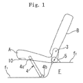
Fig. 1 is a schematic side view of a tip-up type automotive seat according to an embodiment of the present invention; -
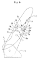
Fig. 2 is a side view of a tipping-up lock mechanism provided at the automotive seat shown inFig. 1 ; -
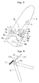
Fig. 3 is a schematic fragmentary side view which is of assistance in explaining a principle of locking of a seat cushion of the automotive seat by the tipping-up lock mechanism shown inFig.2 ; -
Fig. 4 is a schematic side view illustrating a stand leg portion provided at the tip-up type automotive seat shown inFig. 1 ; -
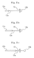
Figs. 5a, 5b, and 5c are each an explanatory view of a condition of a wire coupled to the stand leg portion, during pivotal movement of the seat cushion; -
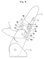
Fig. 6 is a schematic view which is of assistance in explaining operation of the tipping-up lock mechanism ofFig. 2 by which the seat cushion is unlocked with respect to a seat back of the automotive seat; -
Fig. 7 is an explanatory view of a condition in which the seat cushion is unlocked with respect to the seat back; -
Fig. 8 is a schematic side view of the automotive seat which is of assistance in explaining the pivotal movement of the seat cushion to a middle position from a used position; -
Fig. 9 is a schematic side view of the automotive seat in which the seat cushion is located in the middle position; -
Fig. 10 is a schematic view which is of assistance in explaining returning of a latch and a cam of the tipping-up lock mechanism to their original positions; -
Fig. 11 a schematic view illustrating a condition where the seat cushion is locked in the middle position by the tipping-up lock mechanism; -
Fig. 12 is a schematic side view illustrating a condition where the seat cushion is pivoted to a tipped-up position; and -
Fig. 13 is a schematic side view illustrating a condition where the seat cushion is locked in the tipped-up position by the tipping-up lock mechanism. - Referring to
Fig. 1 , there is illustrated a tip-up type automotive seat according to an embodiment of the present invention, which includes a seat cushion A and a seat back B. Referring toFig. 2 , the seat cushion includes a pair of spaced apartside brackets 1 serving as side frame sections of a seat cushion frame for the seat cushion, and the seat back includes a pair of spaced apartside brackets 2 serving as side frame sections of a seat back frame for the seat back (only oneside bracket 1 of the seat cushion and only oneside bracket 2 of the seat back are shown inFig. 2 ). Theside brackets 1 of the seat cushion are pivotally supported at upwardly curved rear portions thereof to portions of theside brackets 2 of the seat back, which are adjacent lower end portions of theside brackets 2 of the seat back, bysupport pins 3, so that the seat cushion is allowed to be pivoted or tipped up around thesupport pins 3 from a used position, at which the seat cushion becomes a substantially horizontal posture, to a tipped-up position at which the seat cushion becomes opposed to the seat back in a substantially vertical posture. - As shown in
Fig. 1 , the tip-up type automotive seat is provided with a stand leg portion 4. The stand leg portion 4 is formed into a substantially U-shape in outline and pivotally supported at upper end regions of spaced apart vertical portions thereof to lower regions of forward portions of the side brackets of the seat cushion A bysupport pins 4a. Areceiving base 4b for receiving and releasably engaging a lower horizontal portion of the stand leg portion 4 is mounted on a lower step portion f1 of an automotive body floor F. The stand leg portion 4 is adapted to be releasably engaged at the lower horizontal portion thereof with thereceiving base 4b so as to be obliquely stand up from the lower step portion f1 of the automotive body floor F, whereby when the seat cushion is locked in the used position by a tipping-up lock mechanism for releasably locking the seat cushion with respect to the seat back and preventing the pivotal movement of the seat cushion, which will be discussed in detail hereinafter, the seat cushion is maintained in the substantially horizontal posture by the stand leg portion 4. Moreover, the seat back are supported at the lower end portions of the side brackets thereof to a pair of spaced apartbase brackets 5 mounted on an upper step portion f2 of the automotive body floor F so as to stand up from the upper step portion f2. - As briefly discussed above, the tip-up type automotive seat according to the embodiment of the present invention is provided with the tipping-up lock mechanism. In the illustrated example, the tipping-up lock mechanism is provided on one of both sides of the automotive seat. As shown in
Fig. 2 , the upwardly curved rear portions of theside brackets 1 of the seat cushion have substantially semicircle-shaped edges extending about thesupport pins 3 of theside brackets 1. The tipping-up lock mechanism includes first, second, and third spaced apartcutout teeth side brackets 1 of the seat cushion so as to be in turn arranged from a rearward direction of the substantially semicircle-shaped edge to a forward direction of the substantially semicircle-shaped edge. More particularly, thefirst cutout tooth 6a, thesecond cutout tooth 6b, and thethird cutout tooth 6c are provided at a rearward region of the substantially semicircle-shaped edge, at a middle region of the substantially semicircle-shaped edge, and at a forward region of the substantially semicircle-shaped edge, respectively. Thefirst cutout tooth 6a serves as means to facilitate causing of the seat cushion to be kept in the used position. Thethird cutout tooth 6c serves as means to facilitate causing of the seat cushion to be kept in the tipped-up position. Thesecond cutout tooth 6b serves as means to facilitate causing of the seat cushion to be kept in a middle position between the used position and the tipped-up position. - The tipping-up lock mechanism further includes a latch 7 and a
cam 8. The latch 7 is pivotally supported at aforward portion 7a thereof to acorresponding side bracket 2 of the seat back by asupport pin 70 so as to be swingable upward. Thecam 8 includes a body and alower portion 8a extending downward from the cam body. Thecam 8 is swingably supported at a substantially middle portion thereof to theside bracket 2 of the seat back by asupport pin 80 with thelower portion 8a being directed toward an upper region of arearward potion 7b of the latch 7. - The latch 7 is provided at a lower edge of the
rearward portion 7b thereof with a protrudingtooth 71 which is adapted to be selectively and releasably engaged with the first, second, andthird cutout teeth tooth 71 of the latch 7 can be securely engaged with the second andthird cutout teeth tooth 71 is configured to include two protruding tooth-portions which are spaced apart from each other in the forward/rearward direction. Incidentally, thefirst cutout tooth 6a is configured to have a recess portion which extends along a region of the substantially semicircle-shaped edge of theside bracket 1 and is adapted to receive the protrudingtooth 71 of the latch 7 during the pivotal movement of the seat cushion to the used position from the middle position or the tipped-up position. - In addition to the protruding
tooth 71, the latch 7 includes anengaging step portion 72 against which thelower portion 8a of thecam 8 is abutted, and arecess portion 73 for allowing thecam 8 to be swung. Theengaging step portion 72 and therecess portion 73 are formed in the upper region of therearward portion 7b of the latch 7. Therecess portion 73 of the latch 7 extends continuously from an edge of theengaging step portion 72 and is formed so as to have a depth which is not less than a height of an engaged portion between the protrudingtooth 71 of the latch 7 and each of the first, second, andthird cutout teeth tooth 71 of the latch 7 can be escapingly disengaged from thecutout teeth - Referring now to
Fig. 3 , an angle of thecam 8 relative to the latch 7 is set in such a manner that an angleθbetween a reference line L1 connecting an axial center O1 of thesupport pin 70 of the latch 7 and an abutment point P of thelower portion 8a of thecam 8 against the engaging step portion 72 (Fig. 2 ), and a line L2 connecting an axial center O2 of thesupport pin 80 of thecam 8 and the abutment point P is kept to be an acute angle. Thus, thecam 8 functions as a prop with respect to theengaging step portion 72 of the latch 7, so that when thelower portion 8a of thecam 8 is abutted against theengaging step portion 72 of the latch 7, the engagement between the protrudingtooth 71 of the latch 7 and thecutout tooth side bracket 1 of the seat cushion can be positively maintained. A bottom surface of theengaging step portion 72 of the latch 7 is formed so as to be adjacent theprotruding tooth 71 of the latch 7, so that the reference line L1 is set so as to be descent rearward from the axial center O1 of thesupport pin 70 of the latch 7. - In the illustrated example, the
lower portion 8a of thecam 8 is formed into a substantially semiellipse-shape. Correspondingly to such a shape of thelower portion 8a of thecam 8, the bottom surface of the engagingstep portion 72 of the latch 7 is formed into a substantially J-shape. Moreover, the substantially J-shaped bottom surface of the engagingstep portion 72 is formed so as to have a curve surface which allows at least half or more region of thelower portion 8a of thecam 8 to be received by the engagingstep portion 72, so that thelower portion 8a of thecam 8 can be positively abutted against the engagingstep portion 72 of the latch 7 and stably received by the engagingstep portion 72. - In the illustrated example, the
recess portion 73 of the latch 7 may be formed into a substantially U-shape which has a depth larger than the height of the engaged portion between the protrudingtooth 71 of the latch 7 and each of the first, second, andthird cutout teeth side bracket 1 of the seat cushion and which fits thelower portion 8a of thecam 8. When thecam 8 is pulled up as will be discussed in detail hereinafter, therecess portion 73 of the latch 7 serves to allow thecam 8 to be swung up in such a manner that thelower portion 8a of thecam 8 slips into therecess portion 73 of the latch 7 while being disengaged from the engagingstep portion 72. As thelower portion 8a of thecam 8 slips into therecess portion 73 of the latch 7, the latch 7 is swung up. By the swinging-up of the latch 7 which is brought about by the swinging-up of thecam 8, the protrudingtooth 71 of the latch 7 is positively disengaged from any one of thecutout teeth side bracket 1 of the seat cushion. - The
cam 8 is formed into a substantially L-shape in outline. Awire 9 of a first wire cable which is inserted through a tube of the first wire cable is coupled at one end portion thereof to anupper end portion 8b of the cam body. The other end portion of thewire 9 is connected to an operating lever 10 (seeFig. 1 ). As shown inFig. 1 , the operatinglever 10 is swingably provided in a recess portion formed in a lower region of a forward section of the seat cushion A and is adapted to be pulled by a person. When the person inserts his/her hand into the recess portion of the seat cushion A and pulls the operatinglever 10 with his/her hand, the tipping-up lock mechanism becomes unlocked as will be discussed in detail hereinafter. In the condition where the tipping-up lock mechanism is unlocked, the person can manually cause the seat cushion to be tipped up in one motion. - Referring to
Fig. 4 , the stand leg portion 4 is typically urged toward a stored position under the seat cushion by atension spring 11 which is retained at one end thereof to an upper end region of one of the spaced apart vertical portions of the substantially U-shaped stand leg portion 4 which is located upward of asupport pin 4a of the vertical portion, and retained at the other end thereof to a forward portion of the side bracket of the seat cushion. Moreover, a wire of asecond wire cable 12 which is inserted through atube 12c of thesecond wire cable 12 is coupled at oneend portion 12a thereof to the upper end region of the vertical portion of the substantially U-shaped stand leg portion 4 and coupled at the other end portion thereof (not shown) to the seat back. - Referring to
Figs. 5a to 5c , theother end portion 12b of the wire of thesecond wire cable 12 is supported to a retainingpiece 13 which is provided at a suitable portion of the seat back frame. Theother end portion 12b of the wire of thesecond wire cable 12 is provided with a spherical end stop 12d and penetrated through a slit of the retainingpiece 13 so as to be movable relative to the retainingpiece 13. - When the seat cushion is located at the used position, the wire of the
second wire cable 12 is in a condition shown inFig. 5a . In this condition, when the person causes the seat cushion to be released from the seat back by operating the operating lever 10 (Fig. 1 ) and then causes the seat cushion to be tipped up toward a position just before the middle position while allowing the stand leg portion 4 to be disengaged from the receivingbase 4b (Fig. 1 ) due to the tipping-up movement of the seat cushion, the wire of thesecond cable 12 is pulled against an action of the tension spring (as shown inFig. 5b ) so as to allow the stand leg portion 4 to be pivoted toward a developed position until the seat cushion reaches the position just before the middle position. On the other hand, as the seat cushion is pivoted toward the middle position from the position just before the middle position, the action of the tension spring 11 (Fig. 4 ) is exerted on the wire of thesecond wire cable 12, whereby the wire of thesecond wire cable 12 is moved in such a manner that thewire end portion 12b thereof is moved relative to the retainingpiece 13 so as to project from the retainingpiece 13 as shown inFig. 5c . Thus, when the seat cushion reaches the middle position, the stand leg portion 4 is moved to the stored position by the action of thetension spring 11. More particularly, the stand leg portion 4 can be pivoted toward the stored position synchronously with the tipping-up movement of the seat cushion and can be pivoted toward the developed position synchronously with returning of the seat cushion to the used position. Incidentally, any suitable conventional compensator (not shown) for compensating a pulling force exerted on the wire of thesecond cable wire 12 and adjusting a total length of the wire of thesecond wire cable 12 is provided at a suitable portion of the wire of thesecond wire cable 12. - In the tip-up type automotive seat constructed as discussed above, when the operating
lever 10 is pull-operated by the person, an upward pulling force is applied to thecam 8 through thewire 9 of the first wire cable as shown inFig. 6 . By the pulling force, thecam 8 is swung in a clockwise direction around thesupport pin 80, whereby thelower portion 8a of thecam 8 is disengaged from the engagingstep portion 72 of the latch 7 and slips into therecess portion 73 of the latch 7. - As the
lower portion 8a of thecam 8 is moved toward therecess portion 73 of the latch 7 and slips into therecess portion 73, the latch 7 is swung upward in a counterclockwise direction about thesupport pin 70, whereby the protrudingtooth 71 of the latch 7 is disengaged from thecutout tooth 6a (6b or 6c) as shown inFig. 7 . Thus, the seat cushion is brought to an unlocked condition where it is released from the seat back. As discussed above, therecess portion 73 of the latch 7 is formed so as to have the depth which is not less than the height of the engaged portion between the protrudingtooth 71 of the latch 7 and each of thecutout teeth lower portion 8a of thecam 8 slips into therecess portion 73 and the latch 7 is swung up, the protrudingtooth 71 of the latch 7 can be positively disengaged from thecutout tooth - In a case where the seat cushion is located in the used position, the protruding
tooth 71 of the latch 7 is disengaged from thefirst cutout tooth 6a of theside bracket 1 of the seat cushion by operating the operatinglever 10, and the seat cushion is to be locked in the middle position, the person lifts up the seat cushion with his/her hand while leaving the operatinglever 10 pulled and can cause the seat cushion to be locked in the middle position as shown inFigs. 8 and9 , by releasing his/her hand from the operating lever. In the middle position, the stand leg portion 4 is stored in the stored position. - When the seat cushion reaches the middle position and the operating lever is released from the pulled condition, the latch 7 is swung back about the
support pin 70 by gravity and thecam 8 is also swung back toward its original position by gravity as indicated by arrows inFig. 10 . - When the
cam 8 is swung back toward the original position while being released from therecess portion 73 of the latch 7, and thelower portion 8a of thecam 8 is operatively abutted against the engagingstep portion 72 of the latch 7 as shown inFig. 11 , the protrudingtooth 71 of the latch 7 becomes engaged with thesecond cutout tooth 6b of theside bracket 1 of the seat cushion. At this time, thecam 8 functions as the prop with respect to the latch 7 as discussed above, so that the engagement between the protrudingtooth 71 of the latch 7 and thesecond cutout tooth 6b of theside bracket 1 of the seat cushion can be positively maintained. In this condition, any baggage or luggage can be stored in a space between the seat cushion locked in the middle position and the seat back in the substantially vertical posture. Even if the baggage or luggage is stored in the space between the seat cushion locked in the middle position and the seat back in the substantially vertical posture, the seat cushion can withstand a load applied to the seat cushion by the baggage of luggage, since the seat cushion is locked with respect to the seat back by the tipping-up lock mechanism. - Moreover, in a case where the seat cushion locked in the middle position is be pivoted to the tipped-up position from the middle position, the person causes the protruding
tooth 71 of the latch 7 to be disengaged from thesecond cutout tooth 6b of theside bracket 1 by pull-operating the operating lever in the same manner as discussed above and can cause the seat cushion to be pivoted to the tipped-up position. When the seat cushion reaches the tipped-up position as shown inFig. 12 and the operating lever is released from the pulled-condition, the protrudingtooth 71 of the latch 7 becomes operatively engaged with thethird cutout tooth 6c of theside bracket 1 of the seat cushion as shown inFig. 13 . Thus, the seat cushion is locked in the tipped-up position by the tipping-up lock mechanism. - Moreover, in a case where the seat cushion locked in the tipped-up position is to be returned to the used position, the person causes the protruding
tooth 71 of the latch 7 to be disengaged from thethird cutout tooth 6c of theside bracket 1 of the seat cushion by pull-operating the operating lever in the same manner as discussed above and can cause the seat cushion to be returned to the used position. When the seat cushion reaches the used position and the operating lever is released from the pulled-condition, thecam 8 and the latch 7 are returned to their original positions by gravity and the protrudingtooth 71 of the latch 7 becomes operatively engaged with thefirst cutout tooth 6a of theside bracket 1 of the seat cushion. Thus, the seat cushion is locked in the used position by the tipping-up lock mechanism. As the seat cushion passes the middle position and reaches to a position before the used position, the stand leg portion is pivoted and reaches the developed position at which the stand leg portion 4 is then operatively engaged with the receivingbase 4b. - While the case where the tipping-up lock mechanism is provided on the one side of the automotive seat has been discussed above with respect to the embodiment, a second tipping-up lock mechanism constructed in the same manner as the first tipping-up lock mechanism is done may be provided on the other side of the automotive seat. In this case, a cam of the second tipping-up lock mechanism is coupled to the operating
lever 10 via a wire cable. - The terms and expressions which have been employed are used as terms of description and not of limitation, and there is no intention in the use of such terms and expressions of excluding any equivalents of the features shown and description, or portions thereof, but it is recognized that various modifications are possible with the scope of the invention claimed.
Claims (2)
- A tip-up type automotive seat comprising:a seat back including a pair of first spaced apart side brackets;a seat cushion including a pair of second spaced apart side brackets;said second side brackets having upwardly curved rear portions;said second side brackets being pivotally supported at said upward curved rear portions thereof to portions of said first side brackets of said seat back, which are adjacent lower end portions of said first side brackets of said seat back, by first support pins, whereby said seat cushion is allowed to be pivoted about said first support pins from a used position, at which said seat cushion becomes a substantially horizontal posture, to a tipped-up position at which said seat cushion becomes opposed to said seat back in a substantially vertical posture;said upwardly curved rear portions of said second side brackets being formed so as to have substantially semicircle-shaped edges extending around said first support pins;a tipping-up lock mechanism for selectively and releasably locking said seat cushion with respect to said seat back, in said used position, said tipped-up position, and a middle position between said used position and said tipped-up position;said tipping-up lock mechanism including a latch, a cam, and first, second, and third cutout teeth;said first, second, and third cutout teeth being provided at a substantially semicircle-shaped edge of an upward curved rear portion of one of said second side brackets so as to be in turn arranged from a rearward direction of said substantially semicircle-shaped edge toward a forward direction of said substantially semicircle-shaped edge;said first cutout tooth serving as means to facilitate causing of said seat cushion to be releasably locked in said used position;said second cutout tooth serving as means to facilitate causing of said seat cushion to be releasably locked in said middle position;said third cutout tooth serving as means to facilitate causing of said seat cushion to be releasably locked in said tipped-up position;said latch being swingably supported via a second support pin to corresponding one of said first side brackets of said seat back;said latch including a protruding tooth provided at a lower edge of a rearward portion of said latch for selectively and releasably engaging said first, second, and third cutout teeth, an engaging step portion formed in an upper region of said rearward portion of said latch, and a recess portion formed in said upper region of said rearward portion of said latch so as to continue from an edge of said engaging step portion;said cam having a body and a lower portion extending downward from said cam body;said cam being swingably supported via a third support pin to said corresponding one of said first side brackets of said seat back with said lower portion thereof being releasably abutted against said engaging step portion of said latch;said cam having an angle with respect to said latch, said angle being set in such a manner that an angle between a reference line connecting an axial center of said second support pin of said latch and an abutment point of said lower portion of said cam against said engaging step portion of said latch, and a line connecting an axial center of said third support pin of said cam and said abutment point is kept to be an acute angle; andan operating lever coupled to said cam for causing said tipping-up lock mechanism to be unlocked and causing said seat cushion to be brought to a condition where said seat cushion is allowed to be pivoted;said recess portion of said latch having a depth which is not less than a height of an engaged portion between said protruding tooth of said latch and each of said first, second, and third cutout teeth, so that when said cam is pulled up by pulling of said operating lever, said cam is swung up in such a manner that said lower portion of said cam is disengaged from said engaging step portion of said latch and slips into said recess portion of said latch, and said latch is swung up as said lower portion of said cam slips into said recess portion of said latch, whereby said protruding tooth of said latch is disengaged from any one of said first, second, and third cutout teeth and said seat cushion is brought to a condition where it is allowed to be pivoted and, when said operating lever is released from the pulled condition, said latch and said cam are returned to their original positions by gravity, whereby said protruding tooth of said latch becomes engaged with any one of said first, second, and third cutout teeth.
- A tip-up type automotive seat according to claim 1, wherein said lower portion of said cam is formed into a substantially semiellipse-shape, a bottom surface of said engaging step portion of said latch is formed into a substantially J-shape, and said recess portion of said latch is formed into a substantially U-shape having a depth larger than said height of said engaged portion between said protruding tooth of said latch and each of said first, second, and third cutout teeth.
Applications Claiming Priority (2)
| Application Number | Priority Date | Filing Date | Title |
|---|---|---|---|
| JP2005378862A JP4858816B2 (en) | 2005-12-28 | 2005-12-28 | Chip-up type car seat |
| PCT/JP2006/326415 WO2007077980A1 (en) | 2005-12-28 | 2006-12-28 | Tip-up type automotive seat |
Publications (3)
| Publication Number | Publication Date |
|---|---|
| EP1997674A1 true EP1997674A1 (en) | 2008-12-03 |
| EP1997674A4 EP1997674A4 (en) | 2009-11-11 |
| EP1997674B1 EP1997674B1 (en) | 2011-02-02 |
Family
ID=38228319
Family Applications (1)
| Application Number | Title | Priority Date | Filing Date |
|---|---|---|---|
| EP06843784A Not-in-force EP1997674B1 (en) | 2005-12-28 | 2006-12-28 | Tip-up type automotive seat |
Country Status (4)
| Country | Link |
|---|---|
| EP (1) | EP1997674B1 (en) |
| JP (1) | JP4858816B2 (en) |
| DE (1) | DE602006019986D1 (en) |
| WO (1) | WO2007077980A1 (en) |
Cited By (1)
| Publication number | Priority date | Publication date | Assignee | Title |
|---|---|---|---|---|
| FR2933345A1 (en) * | 2008-07-02 | 2010-01-08 | Faurecia Sieges Automobile | SEAT OF A MOTOR VEHICLE AND VEHICLE PROVIDED WITH SUCH A SEAT |
Families Citing this family (3)
| Publication number | Priority date | Publication date | Assignee | Title |
|---|---|---|---|---|
| KR101543033B1 (en) | 2009-06-05 | 2015-08-13 | 주식회사다스 | One-touch paddle type recliner unit |
| JP2016222139A (en) * | 2015-06-01 | 2016-12-28 | トヨタ紡織株式会社 | Vehicle seat |
| JP7366768B2 (en) * | 2020-01-22 | 2023-10-23 | アディエント・エンジニアリング・アンド・アイピー・ゲゼルシャフト・ミット・ベシュレンクテル・ハフツング | vehicle seat |
Family Cites Families (4)
| Publication number | Priority date | Publication date | Assignee | Title |
|---|---|---|---|---|
| US4919482A (en) * | 1987-01-20 | 1990-04-24 | Lear Siegler Seating Corp. | Inertia latch for vehicle seats |
| JP3663509B2 (en) * | 2001-06-11 | 2005-06-22 | テイ・エス テック株式会社 | Inertia lock device and folding seat |
| JP2003011707A (en) * | 2001-07-03 | 2003-01-15 | Tachi S Co Ltd | Vehicle seat with tip-up mechanism |
| JP4263628B2 (en) * | 2004-01-28 | 2009-05-13 | 本田技研工業株式会社 | Sheet storage device |
-
2005
- 2005-12-28 JP JP2005378862A patent/JP4858816B2/en not_active Expired - Fee Related
-
2006
- 2006-12-28 EP EP06843784A patent/EP1997674B1/en not_active Not-in-force
- 2006-12-28 DE DE602006019986T patent/DE602006019986D1/en active Active
- 2006-12-28 WO PCT/JP2006/326415 patent/WO2007077980A1/en not_active Ceased
Cited By (1)
| Publication number | Priority date | Publication date | Assignee | Title |
|---|---|---|---|---|
| FR2933345A1 (en) * | 2008-07-02 | 2010-01-08 | Faurecia Sieges Automobile | SEAT OF A MOTOR VEHICLE AND VEHICLE PROVIDED WITH SUCH A SEAT |
Also Published As
| Publication number | Publication date |
|---|---|
| JP2007176394A (en) | 2007-07-12 |
| WO2007077980A1 (en) | 2007-07-12 |
| EP1997674A4 (en) | 2009-11-11 |
| EP1997674B1 (en) | 2011-02-02 |
| JP4858816B2 (en) | 2012-01-18 |
| DE602006019986D1 (en) | 2011-03-17 |
Similar Documents
| Publication | Publication Date | Title |
|---|---|---|
| US9821684B2 (en) | Tip-up/dive-down type reclining seat for vehicle | |
| EP2049359B1 (en) | Vehicular seat device | |
| JP5098279B2 (en) | Vehicle seat device | |
| US8205944B2 (en) | Arrangement lever device for automobile seat | |
| US9566880B2 (en) | Vehicle seat | |
| EP2062773A1 (en) | Slide/swing-up type automobile seat | |
| US7712829B2 (en) | Seat structure for vehicle | |
| US20090295185A1 (en) | Tip-Up/Dive-Down Type Reclining Seat for Vehicle | |
| JP2008254663A (en) | Seat lock device | |
| JP2003327028A (en) | Vehicle seat device | |
| JP2007176404A (en) | Tip-up/dive-down type reclining seat for automobile | |
| EP1997674B1 (en) | Tip-up type automotive seat | |
| JP5112188B2 (en) | Retractable seat for vehicle | |
| EP2028037A2 (en) | Vehicle seat | |
| JP5913056B2 (en) | Sliding device for vehicle seat | |
| JP4858819B2 (en) | Tip-up / dive-down automotive reclining seat | |
| JP5082490B2 (en) | Vehicle seat | |
| JP3639537B2 (en) | Vehicle slide seat | |
| JP2003291702A (en) | Sheet | |
| JP5987036B2 (en) | Vehicle seat device | |
| JP4901380B2 (en) | Strap for vehicle seat operation | |
| JP2005297629A (en) | Folding type footrest structure of vehicle | |
| CN104812618B (en) | Seat sliding device for vehicles | |
| JP2008189085A (en) | Seat adjustment device for automobile | |
| JP2006123578A (en) | Holding device for vehicle seat |
Legal Events
| Date | Code | Title | Description |
|---|---|---|---|
| PUAI | Public reference made under article 153(3) epc to a published international application that has entered the european phase |
Free format text: ORIGINAL CODE: 0009012 |
|
| 17P | Request for examination filed |
Effective date: 20080728 |
|
| AK | Designated contracting states |
Kind code of ref document: A1 Designated state(s): DE FR GB |
|
| DAX | Request for extension of the european patent (deleted) | ||
| RBV | Designated contracting states (corrected) |
Designated state(s): DE FR GB |
|
| A4 | Supplementary search report drawn up and despatched |
Effective date: 20090910 |
|
| 17Q | First examination report despatched |
Effective date: 20091203 |
|
| R17C | First examination report despatched (corrected) |
Effective date: 20100617 |
|
| GRAP | Despatch of communication of intention to grant a patent |
Free format text: ORIGINAL CODE: EPIDOSNIGR1 |
|
| GRAS | Grant fee paid |
Free format text: ORIGINAL CODE: EPIDOSNIGR3 |
|
| GRAA | (expected) grant |
Free format text: ORIGINAL CODE: 0009210 |
|
| AK | Designated contracting states |
Kind code of ref document: B1 Designated state(s): DE FR GB |
|
| REG | Reference to a national code |
Ref country code: GB Ref legal event code: FG4D |
|
| REF | Corresponds to: |
Ref document number: 602006019986 Country of ref document: DE Date of ref document: 20110317 Kind code of ref document: P |
|
| REG | Reference to a national code |
Ref country code: DE Ref legal event code: R096 Ref document number: 602006019986 Country of ref document: DE Effective date: 20110317 |
|
| PLBE | No opposition filed within time limit |
Free format text: ORIGINAL CODE: 0009261 |
|
| STAA | Information on the status of an ep patent application or granted ep patent |
Free format text: STATUS: NO OPPOSITION FILED WITHIN TIME LIMIT |
|
| 26N | No opposition filed |
Effective date: 20111103 |
|
| REG | Reference to a national code |
Ref country code: DE Ref legal event code: R097 Ref document number: 602006019986 Country of ref document: DE Effective date: 20111103 |
|
| PGFP | Annual fee paid to national office [announced via postgrant information from national office to epo] |
Ref country code: GB Payment date: 20141224 Year of fee payment: 9 |
|
| PGFP | Annual fee paid to national office [announced via postgrant information from national office to epo] |
Ref country code: FR Payment date: 20141208 Year of fee payment: 9 |
|
| PGFP | Annual fee paid to national office [announced via postgrant information from national office to epo] |
Ref country code: DE Payment date: 20141223 Year of fee payment: 9 |
|
| REG | Reference to a national code |
Ref country code: DE Ref legal event code: R119 Ref document number: 602006019986 Country of ref document: DE |
|
| GBPC | Gb: european patent ceased through non-payment of renewal fee |
Effective date: 20151228 |
|
| REG | Reference to a national code |
Ref country code: FR Ref legal event code: ST Effective date: 20160831 |
|
| PG25 | Lapsed in a contracting state [announced via postgrant information from national office to epo] |
Ref country code: GB Free format text: LAPSE BECAUSE OF NON-PAYMENT OF DUE FEES Effective date: 20151228 Ref country code: DE Free format text: LAPSE BECAUSE OF NON-PAYMENT OF DUE FEES Effective date: 20160701 |
|
| PG25 | Lapsed in a contracting state [announced via postgrant information from national office to epo] |
Ref country code: FR Free format text: LAPSE BECAUSE OF NON-PAYMENT OF DUE FEES Effective date: 20151231 |