JP2005297629A - Folding type footrest structure of vehicle - Google Patents
Folding type footrest structure of vehicle Download PDFInfo
- Publication number
- JP2005297629A JP2005297629A JP2004113153A JP2004113153A JP2005297629A JP 2005297629 A JP2005297629 A JP 2005297629A JP 2004113153 A JP2004113153 A JP 2004113153A JP 2004113153 A JP2004113153 A JP 2004113153A JP 2005297629 A JP2005297629 A JP 2005297629A
- Authority
- JP
- Japan
- Prior art keywords
- footrest
- seat
- floor
- vehicle
- occupant
- Prior art date
- Legal status (The legal status is an assumption and is not a legal conclusion. Google has not performed a legal analysis and makes no representation as to the accuracy of the status listed.)
- Pending
Links
- 230000004308 accommodation Effects 0.000 abstract 1
- 210000002683 foot Anatomy 0.000 description 35
- 210000003371 toe Anatomy 0.000 description 6
- NJPPVKZQTLUDBO-UHFFFAOYSA-N novaluron Chemical compound C1=C(Cl)C(OC(F)(F)C(OC(F)(F)F)F)=CC=C1NC(=O)NC(=O)C1=C(F)C=CC=C1F NJPPVKZQTLUDBO-UHFFFAOYSA-N 0.000 description 4
- 238000010586 diagram Methods 0.000 description 2
- 238000000034 method Methods 0.000 description 2
- 238000007796 conventional method Methods 0.000 description 1
- 230000000452 restraining effect Effects 0.000 description 1
- 230000000630 rising effect Effects 0.000 description 1
Images

Landscapes
- Passenger Equipment (AREA)
Abstract
Description
本発明は、通常状態から使用位置に回動することにより斜めに立ち上がる足載せ面を備えた車両の可倒式フットレスト構造に関する。 The present invention relates to a retractable footrest structure for a vehicle having a footrest surface that rises obliquely by rotating from a normal state to a use position.
この種の従来の可倒式フットレスト構造として、例えば、前方側シートのシートバック下端部に、フットレスト本体を回動可能に設けて、フットレスト本体の足載せ面を斜めに傾斜させて、後方側シート側乗員の足を載せるように構成したものがある(特許文献1参照)
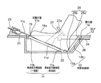
また、他の例として、図11に示したものが知られている (特許文献2参照)。
図11によれば、プレート状のフットレスト本体1が、前方側シート7のシートバック7aの僅かに後方よりのフロア2に形成された凹部2aの開口部3に通常状態でフロア2と同一面状にセットされると共に、フットレスト本体1の車体後方側端部1aが開口部3の車体後方側に枢着されている。
According to FIG. 11, the plate-
更に、フットレスト本体1に、フットレスト本体1がフロア2に対して斜めに立ち上がった使用位置に支持する支持部材4の基端部が枢着されると共に、開口部3の周辺に、フットレスト本体1を上方へ回動させるように、支持部材4の先端部をフロア2に沿ってスライド可能にガイドするガイド部材5が設けられている。
Further, a base end portion of a support member 4 that supports the
ガイド部材5に、使用位置に回動されたフットレスト本体1を拘束するように、支持部材4の先端部を拘束する凹状ストッパ5a、5bが形成されている。
The
このように構成する従来の可倒式フットレスト構造によれば、図示するように、フットレスト本体1は、その車体後方側端部1aを中心に車体前方側端部1bがフロア2に対して遠ざかり、上面における足載せ面1cをフロア2に対して斜めに立ち上がらせて使用位置にし、後方側シート(不図示)に乗車している乗員の足8が載せられるようになっている。
According to the conventional retractable footrest structure configured as described above, as shown in the figure, the footrest
しかしながら、上記のように構成するいずれの従来の可倒式フットレスト構造は同様の課題を内包しているが、図11に示す従来例を代表して説明すると、特に、乗員が着座した着座シートである後方側シートの背もたれをリクライニングさせて着座するような場合には、通常、乗員の足8は車体前方に大きく投げ出して、リラックス姿勢を保持したいところであるが、前方側シート7の背もたれ7a等により阻まれて、足8を思い切り伸ばすことができず、乗員の思い通りのリラックス姿勢が確保することができない。
However, any of the conventional retractable footrest structures configured as described above includes the same problem. However, as a representative example shown in FIG. When seating with the backrest of a certain rear seat reclining, the occupant's feet 8 are usually thrown forward to the front of the vehicle body to maintain a relaxed posture, but the
そこで、いっそのこと、上記したような可倒式フットレスト構造を設置せず、図12に示すように、後方側シート6に着座した乗員の足8を前方側シート7の着座部7bの下方の隙間に潜り込ませて、足8を思い切り伸ばしたリラックス姿勢を取るように構成しまうことが考えられるが、このリラックス姿勢をとることにより、乗員の足8つま先が、ちょうど前方側シート7の着座部7bの下面に突き当たってしまうことになって、乗員の足8を車体前方に十分投げ出して、乗員が満足するリラックス姿勢をとることがやはりできないことになる。
Therefore, moreover, as shown in FIG. 12, the occupant's foot 8 seated on the
そこで、本発明は、かかる点に鑑み、乗員の足を対向する前方側シートの下方まで伸ばしたとしても、乗員の足が前方側シートの着座部下面に当接しないようにして、乗員の着座姿勢を常にリラックス姿勢に保持できるように構成した車両の可倒式フットレスト構造を提供することを目的としている。 Therefore, in view of such a point, the present invention prevents the occupant's feet from coming into contact with the lower surface of the seating portion of the front seat even when the occupant's feet are extended below the opposing front seat. It is an object of the present invention to provide a retractable footrest structure for a vehicle configured so that the posture can be always maintained in a relaxed posture.
上記目的を達成するために、本発明に係る車両の可倒式フットレスト構造は、通常状態から使用位置に回動することにより傾斜する足載せ面を備えた車両の可倒式フットレスト構造であって、足載せ面を有するフットレスト本体の一端部側を前記フロアに蝶着して、他端部側を回動可能に構成し、他端部側を前記フロアに凹設設置した凹状収納部内に没入させることによって足載せ面が傾斜する使用位置になるように構成したことを特徴とする。 In order to achieve the above object, a retractable footrest structure for a vehicle according to the present invention is a retractable footrest structure for a vehicle having a footrest surface that is inclined by rotating from a normal state to a use position. The footrest body having a footrest surface is hinged at one end to the floor, the other end is configured to be rotatable, and the other end is recessed into the recessed storage portion installed on the floor. It is characterized in that it is configured to be in a use position where the footrest surface is inclined.
かかる構成を有する本発明によれば、フットレスト本体は、その一端部側をフロアに回動可能に蝶着して、その使用位置において他端部側がフロア側の凹状収納部内に没入するように構成しているため、足載せ面に乗員の足を載せた場合、当該足を凹状収納部内に入り込ませてフロア面より下げた状態で載せることができ、乗員の足を着座している着座側シートに対向する前側シートの着座部下方まで伸ばしたとしても、乗員の足のつま先が前方側シートの着座部に当接することがなく、着座側シートに着座している乗員の着座姿勢を常にリラックス姿勢に保持できることになる。 According to the present invention having such a configuration, the footrest main body is hinged so that one end thereof can be pivoted to the floor, and the other end is inserted into the concave storage portion on the floor side in the use position. Therefore, when an occupant's foot is placed on the footrest surface, the foot can enter the concave storage portion and be lowered from the floor surface, and the seat side seating the occupant's foot Even if the seat is extended to the lower part of the seat on the front seat, the toes of the occupant do not come into contact with the seat on the front seat, and the seated position of the occupant seated on the seat is always relaxed. It will be possible to hold.
また、本発明は、請求項1に記載の発明におけるフットレスト本体の少なくとも他端部側が前方側シートの下方に配設したことを特徴とするものである。
Further, the present invention is characterized in that at least the other end portion side of the footrest body in the invention of
かかる構成を有する本発明によれば、フットレスト本体の少なくとも他端部側が前方側シートの下方に配設することによって、乗員の足のつま先は、着座している着座側シートに対向する前方側シートの着座部下面に位置することになって、乗員の足を思い切って延ばすことができ、乗員の着座姿勢が更にリラックス姿勢に保持できることになる。 According to the present invention having such a configuration, at least the other end side of the footrest body is disposed below the front seat, so that the toes of the occupant's feet are opposed to the seated seat on which the seat is seated. Therefore, it is possible to extend the occupant's feet drastically and maintain the occupant's sitting posture in a more relaxed posture.
上記のように構成する本発明において、フットレスト本体は、その一端部側をフロアに回動可能に蝶着して、その使用位置において他端部側がフロア側の凹状収納部内に没入するように構成しているため、足載せ面に乗員の足を乗せた場合、当該足を凹状収納部内に入り込んでフロア面より下げた状態で載せることができ、乗員の足のつま先を着座している着座側シートに対向する前方側シートの着座部下面に当接させないことになり、着座側シートに着座している乗員の着座姿勢を常にリラックス姿勢に保持できることになる。 In the present invention configured as described above, the footrest body is configured such that one end portion thereof is pivotably hinged to the floor, and the other end portion is immersed in the concave storage portion on the floor side in the use position. Therefore, when the occupant's foot is placed on the footrest surface, the foot can enter the recessed storage part and be lowered from the floor surface, and the seating side where the occupant's foot toes are seated The seat is not brought into contact with the lower surface of the seating portion of the front seat facing the seat, so that the seating posture of the occupant seated on the seating side seat can always be kept in a relaxed posture.
以下、図を用いて、本発明を実施するための最良の実施の形態について説明する。 Hereinafter, the best mode for carrying out the present invention will be described with reference to the drawings.
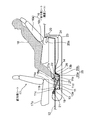
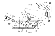
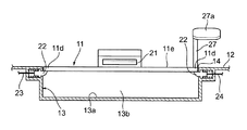
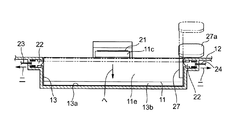
図1は本発明に係る第1の実施の形態を採用した車両の可倒式フットレスト構造の一部縦断して描画した側面図、図2は図1における要部拡大図、図3は同じくフットレスト本体の不使用時の説明図、図4は同じくフットレスト本体の使用時の説明図、図5は図3のA−A断面図、図6は図4のB−B断面図、図7は同じくフットレスト本体を使用時から不使用時に戻す過程を示す説明図である。 1 is a side view of a part of a retractable footrest structure of a vehicle adopting the first embodiment of the present invention. FIG. 2 is an enlarged view of a main part in FIG. 1, and FIG. 4 is an explanatory diagram when the main body is not used, FIG. 4 is also an explanatory diagram when the footrest main body is used, FIG. 5 is a cross-sectional view taken along the line AA in FIG. 3, FIG. It is explanatory drawing which shows the process in which a footrest main body is returned from use at the time of non-use.
図1乃至図6において、車両例えば乗自動車等のフロア12上には、車両前後方向2列に後方側シート16及び前方側シート17が配設されている。
1 to 6, a
後方側シート16は、現在背もたれ部16aがリクライニング状態になっており、乗員18が着座していることから、着座側シートといえる。
The
そして、フロア12には、後方側シート16の前方において且つ前方側シート17の着座部17aに前方側が一部潜り込むような状態で、凹状収納部13が凹設されている。
The
凹状収納部13は、上部が開口部14となっており、開口部14における車体前端部には、板状のフットレスト本体11の一端部側である車体前方側端部11bがヒンジピン19を介して蝶着されており、フットレスト本体11の他端部側である車体後方側端部11aを回動自在に構成している。
The
フットレスト本体11の車体前方側端部11bには、更に車体前方側に延在する係合片部11cが形成されており、係合片部11cがフットレスト本体11の使用状態位置を保持するように、フロア12側に設けた使用状態保持用ロック片21の上面側に係合するように構成されている。
An
また、フットレスト本体11の不使用状態を保持すべく、フットレスト本体11の車体左右側両端部11d側は、開口部14の左右両側部におけるフロア12側に設けた不使用状態保持用ロック片22の上面側に係合するように構成している。
Further, in order to maintain the unused state of the footrest
使用状態保持用ロック片21及び不使用状態保持用ロック片22には、それぞれ連結索体23,24の一端側が連結されており、連結索体23,24の他端側は後方側シート16の着座部16bの側面に設置されたロック操作機構20に連結されている。
One end side of the connecting
ロック操作機構20は、操作レバー20aを揺動させることによって、使用状態保持用ロック片21と係合片部11cとの係合操作及び不使用状態保持用ロック片22とフットレスト本体11の車体左右方向両端部11dとの係合操作を行うよう構成されている、凹状収納部13の開口部14は、フットレスト本体11と共に板状のフットレスト補助片25によってフットレスト本体11の不使用時に閉塞するように構成されている。
The
従って、フットレスト補助片25は、その車体後方側端部25aが開口部14の車体後方側においてヒンジピン26を介してフロア12に蝶着され、車体前方側端部25bを回動自在に構成している。
Therefore, the footrest
そして、フットレスト本体11の不使用時に、フットレスト本体11の車体後方側端部11aとフットレスト補助片25の車体前方側端部25bとが互いに略面一に対向して水平状態となって、開口部14を閉塞するようになっている。
When the
また、フットレスト補助片25は、不図示の板ばね等により、常時開口部14を閉塞する側に付勢されている。
Moreover, the footrest auxiliary |
上記のように構成する本実施の形態においては、図1及び図2に示すフットレスト本体11の使用状態では、使用状態保持用ロック片21が係合片部11cとの係合関係を保持して、フットレスト本体11の車体後方側端部11a側を凹状収納部13の底部13aに当接するまで没入させて、フットレスト本体11を凹状収納部13の底部13aに対して前上がり状の斜めに立ち上がらせ、フットレスト本体11の上面である足載せ面11eに後方側シート16の乗員18の足18aを載置させることができる。
In the present embodiment configured as described above, in the use state of the
この時、乗員18の足18aは、前上がり状態で、凹状収納部13内に入り込むことになって、足18aのつま先が前方側シート17の着座部17aの下面に当接しないことになって、後方側シート16にリクライニング状態で着座している乗員18の着座姿勢は常にリラックス状態に保持されていることになる。
At this time, the
そして、フットレスト補助片25は、フットレスト本体11と連動し付勢力に抗して、凹状収納部13の後壁部13b側に添設されて、足18aの踵部がフットレスト本体部11の車体後方側端部11aとの隙間を挿通して、凹状収納部13の底部13a或いは補助片25によって支持されている。
The footrest
このようなフットレスト本体11の使用状態から不使用状態に移行させるには、乗員18の手で、図1に示す操作レバー20aを下方に引き下げることによって、使用状態保持用ロック片21が車体前方側(図中左側)に引き抜かれると共に、不使用状態保持用ロック片22が車体後方(図中右側)に引き抜かれて、使用状態保持用ロック片21における係合片部11cとの係合関係が離脱する。
In order to shift from the use state of the
これによって、フットレスト本体11の車体後方側端部11a及びフットレスト補助片25の車体前方側端部25bが共に付勢力により上方に跳ね上がって、図3及び図5に示すように、フットレスト本体11及びフットレスト補助片25が互いに略水平状態となって、凹状収納部13の開口部14を閉塞することになる。
As a result, both the vehicle body rear
この時、不使用状態保持用ロック片22は、フットレスト本体11の左右側両端部11bの下面に係合して、フットレスト本体11及びフットレスト補助片25が互いに略水平に保持された状態で凹状収納部13の開口部14の閉塞状態を保持しており、乗員18の乗降に際して或いは乗員18がフットレスト本体11を必要としない場合等には、乗員18の足18a等が凹状収納部13に嵌り込んだりすることを防止できる。
At this time, the non-use state holding
かかる状態から、再びフットレスト本体11を使用状態に移行するには、図4に示すように操作レバー20aを矢印イ方向に引き上げることによって、連結索体21を矢印ロ方向に引き上げて、使用状態保持用ロック片21を引っ込めると共に、連結索体24を矢印ハ方向に引いて、不使用状態保持用ロック片22を図6に示すニ方向に引っ込める。
In order to shift the
次に、乗員18の足18aにより、フットレスト本体11の上面左右のどちらか一側部側に設置したフットレバー27のペダル部27aを矢印方向にフットレスト本体11の上面左右一側部側に設置したフットレバー27のペダル部27aを足18aにより図4の矢印ホ方向或いは図6の矢印へ方向に踏むことによって、フットレスト本体11を図4の矢印方向ト方向に開動させるト共に、これに連動してフットレスト補助片25を矢印チ方向に回転させる。
Next, the
この状態で、操作レバー20aを離せば、係合片部11cが再び使用状態保持用ロック片21に係合して、フットレスト本体11の車体後方側端部11a側を凹状収納部13の底部13aに当接するまで没入して、フットレスト本体11をフロア12に対して前上がり状の斜めに立ち上がらせ、フットレスト本体11の上面である足載せ面11eに後方側シート16の乗員18の足18aを載置させることができる。
In this state, when the
この時、フットレスト補助片25は、フットレスト本体11と連動し付勢力に抗して、凹状収納部13の後壁部13b側に添設されて、足18aの踵部がフットレスト本体部11の車体後方側端部11aとの隙間を挿通して、凹状収納部13の底部13aによって支持されている。
At this time, the footrest
そして、このようなフットレスト本体11の使用状態から再び不使用状態に移行するには、図7に示すように、操作レバー20aを矢印リ方向に引き下げ、連結索体23,24を矢印ヌ方向に引き上げて、使用状態保持用ロック片21と係合片部11cとの係合を離脱させることになり、これにより、フットレスト本体11とフットレスト補助片25とが互いに矢印ルおよびオ方向に付勢力により回動して、略水平状態となって、開口部14を閉塞する。
In order to shift from the use state of the
この時、操作レバー20aを元に戻せば、不使用状態保持用ロック片22がフットレスト本体11の左右側両端部11bに係合して、フットレスト本体11の不使用状態を保持することになる。
At this time, if the
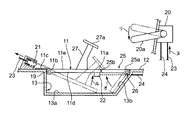
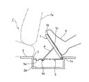
図8は本発明の第2の実施の形態を示しており、図8によれば、上記第1の実施の形態におけるフットレバー27を第2のフットレストとして利用しようとするもので、フットレバー27の設置位置をフットレスト本体11の略中央部側に起立配設することによって、ペダル27aを足掛け部材に構成し、更には、ペダル部27aがフットレバー27に対して枢軸27bを介して首振り動可能に装着し、ペダル部27aの上面を足載せ面に形成したものである。
FIG. 8 shows a second embodiment of the present invention. According to FIG. 8, the
第2の実施の形態によれば、ペダル27aが構成する足載せ面をフットレバー27が構成する足掛け部材が、フットレスト本体11より上方に位置させることができ、乗員18の足18aをより高位置に保持することができる。
According to the second embodiment, the footrest member that the
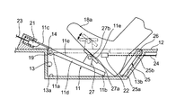
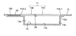
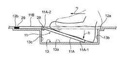
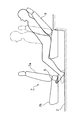
図9及び図10は本発明にかかる第3の実施の形態を示しており、フットレスト本体11が2分割された分割フットレスト体11A、11Bにて構成しており、分割フットレスト体11A及び11Bは、互いに一端側がヒンジピン28を介して折曲可能に構成しており、分割フットレスト体11Aの他端部は凹状収納部13の後壁部13bを臨むようにフロア12に形成した段部12a内に収められている。この結果、この第3の実施の形態では、フットレスト補助片25は廃止されている。
9 and 10 show a third embodiment according to the present invention, in which the
更に、凹状収納部の前壁部13を臨む位置におけるフロア12に台座部12bを形成し、台座部12bと分割フットレスト体11Bの他端との間にスプリング29を縮設すると共に、台座部12e上には、分割フットレスト体11Bがスライド可能に載置されている。
Further, a
かかる構成を有する第3の実施の形態によれば、フットレスト本体11を使用しないときは、図9に示すように、分割フットレスト体11A及び11Bは、略一直線上に保持されていて、凹状収納部13の開口部14を閉塞している。
According to the third embodiment having such a configuration, when the
そして、乗員18がフットレスト本体に足18aを載せてリラックス姿勢を取りたいような場合、足18aによって分割フットレスト体11Aを矢印ワ方向(前方側シート17側)に力を加えると、分割フットレスト体11Bがスプリング29の付勢力に抗して台座部12b上をスライド移動し、これに引き連れてヒンジピン28を介して連結している分割フットレスト体11Aも矢印ワ方向に移動すると共に、分割フットレスト体11Bに対してヒンジピン28を中央にして本体11Aの車体後方側端部11A−1側が凹状収納部13内に没入することになって、分割フットレスト体11Aは車体前方側端部11A−2をフロア12に対して立ち上がらせて斜めにした使用状態に設定できることになる。
When the
このような分割フットレスト体11Aに足18aを載せた使用状態から、足18aを外した場合に、分割フットレスト体11Aは、後方側シート16側(矢印ワ方向に対して逆方向)分割フットレスト体11Bと連動してスプリング29の付勢力によりスライドすると共に、分割フットレスト体11Aの車体後方側端部11A−1側が凹状収納部13内から持ち上がって、分割フットレスト体11Aは分割フットレスト体11Bと共に凹状収納部13の開口部14を閉塞することになり、分割フットレスト体13Aの不使用時には常に、分割フットレスト本体13Aが分割フットレスト体11Bと共に凹状収納部13の開口部14を閉塞することになって、乗員18の足18a等が凹状収納部13に引っ掛かる等の防止ができる。
When the
以上説明したように、本発明は、以上説明したように、本発明は、フットレスト本体は、その一端部側をフロアに回動可能に蝶着して、その使用位置において他端部側がフロア側の凹状収納部内に没入するように構成しているため、足載せ面に乗員の足を載せた場合、当該足を凹状収納部内に入り込ませてフロア面より下げた状態で載せることができ、乗員の足を着座している着座側シートに対向する前側シートの着座部下方まで伸ばしたとしても、乗員の足のつま先が前方側シートの着座部に当接することがなく、着座側シートに着座している乗員の着座姿勢を常にリラックス姿勢に保持できることになるために、通常状態から使用位置に回動することにより斜めに立ち上がる足載せ面を備えた車両の可倒式フットレスト構造に好適である。 As described above, as described above, according to the present invention, the footrest body is hinged so that one end side of the footrest body can be pivoted on the floor, and the other end side is the floor side in the use position. Since the occupant's feet are placed on the footrest surface, the foot can enter the concave storage portion and can be placed in a state of being lowered from the floor surface. Even if the seat is extended to the lower part of the seat on the front seat facing the seat on the seat, the toes of the occupant's feet do not come into contact with the seat on the front seat. It is suitable for a foldable footrest structure of a vehicle having a footrest surface that rises obliquely by rotating from a normal state to a use position, so that the seated posture of the occupant can always be kept in a relaxed posture.
11 フットレスト本体
11a 車体後方側端部(他端部)
11b 車体前方側端部(一端部)
11e 足載せ面
12 フロア
13 凹状収納部
14 開口部
16 後方側シート(着座シート)
17 前方側シート
11
11b Car body front side end (one end)
11e
17 Front seat
Claims (2)
前記足載せ面を有するフットレスト本体の一端部側を前記フロアに蝶着して、他端部側を回動可能に構成し、該他端部側を前記フロアに凹設設置した凹状収納部内に没入させることによって前記足載せ面が傾斜する使用位置になるように構成したことを特徴とする車両の可倒式フットレスト構造。 A retractable footrest structure for a vehicle having a footrest surface that is inclined by rotating from a normal state to a use position,
One end side of the footrest body having the footrest surface is hinged to the floor, and the other end side is configured to be rotatable, and the other end side is provided in a recessed storage portion that is recessedly installed on the floor. A retractable footrest structure for a vehicle, wherein the footrest surface is configured to be in a use position where the footrest surface is inclined by being immersed.
Priority Applications (1)
| Application Number | Priority Date | Filing Date | Title |
|---|---|---|---|
| JP2004113153A JP2005297629A (en) | 2004-04-07 | 2004-04-07 | Folding type footrest structure of vehicle |
Applications Claiming Priority (1)
| Application Number | Priority Date | Filing Date | Title |
|---|---|---|---|
| JP2004113153A JP2005297629A (en) | 2004-04-07 | 2004-04-07 | Folding type footrest structure of vehicle |
Publications (1)
| Publication Number | Publication Date |
|---|---|
| JP2005297629A true JP2005297629A (en) | 2005-10-27 |
Family
ID=35329723
Family Applications (1)
| Application Number | Title | Priority Date | Filing Date |
|---|---|---|---|
| JP2004113153A Pending JP2005297629A (en) | 2004-04-07 | 2004-04-07 | Folding type footrest structure of vehicle |
Country Status (1)
| Country | Link |
|---|---|
| JP (1) | JP2005297629A (en) |
Cited By (3)
| Publication number | Priority date | Publication date | Assignee | Title |
|---|---|---|---|---|
| JP2008260349A (en) * | 2007-04-10 | 2008-10-30 | Kanto Auto Works Ltd | Foot rest structure for automobile |
| JP2018030476A (en) * | 2016-08-25 | 2018-03-01 | 株式会社Subaru | Vehicle driver support device |
| DE102024003502B3 (en) | 2024-10-25 | 2026-03-12 | Mercedes-Benz Group AG | Method for operating a footrest device for a motor vehicle and motor vehicle |
-
2004
- 2004-04-07 JP JP2004113153A patent/JP2005297629A/en active Pending
Cited By (3)
| Publication number | Priority date | Publication date | Assignee | Title |
|---|---|---|---|---|
| JP2008260349A (en) * | 2007-04-10 | 2008-10-30 | Kanto Auto Works Ltd | Foot rest structure for automobile |
| JP2018030476A (en) * | 2016-08-25 | 2018-03-01 | 株式会社Subaru | Vehicle driver support device |
| DE102024003502B3 (en) | 2024-10-25 | 2026-03-12 | Mercedes-Benz Group AG | Method for operating a footrest device for a motor vehicle and motor vehicle |
Similar Documents
| Publication | Publication Date | Title |
|---|---|---|
| CN101495341B (en) | Vehicle Seat Device | |
| JP4223495B2 (en) | Vehicle seat and vehicle with such a seat | |
| JP2004249109A (en) | Folding seat and vehicle comprising the seat | |
| WO2019065773A1 (en) | Vehicular seat | |
| JP4637864B2 (en) | Storage structure for vehicle seat | |
| WO2015098040A1 (en) | Vehicle seat | |
| JP6477215B2 (en) | Vehicle seat | |
| JP5910816B2 (en) | Sheet device | |
| JP2009154681A (en) | Vehicular seat | |
| JP2010012900A (en) | Child seat and support leg | |
| JP2005297629A (en) | Folding type footrest structure of vehicle | |
| JP5099443B2 (en) | Deck board moving mechanism | |
| JP6262526B2 (en) | Vehicle seat | |
| EP1997674B1 (en) | Tip-up type automotive seat | |
| JP5307501B2 (en) | Retractable vehicle seat | |
| JP2010023651A (en) | Foldable seat for vehicle | |
| JP3639537B2 (en) | Vehicle slide seat | |
| JP4260570B2 (en) | Vehicle seat device | |
| JP2008273399A (en) | Cargo board interlocking structure | |
| JP2007313977A (en) | Vehicle seat | |
| JP2004210009A (en) | Folding sheet | |
| JP6483231B2 (en) | Vehicle seat | |
| JP6960360B2 (en) | Vehicle seat | |
| JP2022141002A (en) | headrest device | |
| JP2008230521A (en) | Vehicle seat |
Legal Events
| Date | Code | Title | Description |
|---|---|---|---|
| A621 | Written request for application examination |
Free format text: JAPANESE INTERMEDIATE CODE: A621 Effective date: 20070405 |
|
| A977 | Report on retrieval |
Free format text: JAPANESE INTERMEDIATE CODE: A971007 Effective date: 20091005 |
|
| A131 | Notification of reasons for refusal |
Effective date: 20091013 Free format text: JAPANESE INTERMEDIATE CODE: A131 |
|
| A02 | Decision of refusal |
Free format text: JAPANESE INTERMEDIATE CODE: A02 Effective date: 20100302 |