EP1997660A2 - Door opening and closing apparatus for vehicle - Google Patents
Door opening and closing apparatus for vehicle Download PDFInfo
- Publication number
- EP1997660A2 EP1997660A2 EP08157063A EP08157063A EP1997660A2 EP 1997660 A2 EP1997660 A2 EP 1997660A2 EP 08157063 A EP08157063 A EP 08157063A EP 08157063 A EP08157063 A EP 08157063A EP 1997660 A2 EP1997660 A2 EP 1997660A2
- Authority
- EP
- European Patent Office
- Prior art keywords
- rear hatch
- main body
- movable panel
- hatch main
- open
- Prior art date
- Legal status (The legal status is an assumption and is not a legal conclusion. Google has not performed a legal analysis and makes no representation as to the accuracy of the status listed.)
- Withdrawn
Links
- 230000007246 mechanism Effects 0.000 claims abstract description 32
- 230000003449 preventive effect Effects 0.000 description 14
- 238000000034 method Methods 0.000 description 11
- 230000009471 action Effects 0.000 description 4
- 230000006870 function Effects 0.000 description 4
- 230000008569 process Effects 0.000 description 4
- 230000004044 response Effects 0.000 description 3
- 238000001514 detection method Methods 0.000 description 2
- 238000010586 diagram Methods 0.000 description 2
- 230000007659 motor function Effects 0.000 description 2
- 239000011800 void material Substances 0.000 description 2
- 241001465754 Metazoa Species 0.000 description 1
- 230000000717 retained effect Effects 0.000 description 1
- 238000007789 sealing Methods 0.000 description 1
Images






Classifications
-
- B—PERFORMING OPERATIONS; TRANSPORTING
- B60—VEHICLES IN GENERAL
- B60J—WINDOWS, WINDSCREENS, NON-FIXED ROOFS, DOORS, OR SIMILAR DEVICES FOR VEHICLES; REMOVABLE EXTERNAL PROTECTIVE COVERINGS SPECIALLY ADAPTED FOR VEHICLES
- B60J5/00—Doors
- B60J5/10—Doors arranged at the vehicle rear
- B60J5/12—Doors arranged at the vehicle rear slidable; foldable
Definitions
- This invention generally relates to a door opening and closing apparatus for a vehicle. More particularly, this invention pertains to a door opening and closing apparatus for opening and closing a door such as a rear hatch provided in the rear of a vehicle.
- a known rear hatch includes an opening and closing member (i.e., rear hatch main body) that is hinged at the rear top of a vehicle body (i.e., supporting point) and opens upward, and a movable panel movable in upward and downward directions and accommodated within the opening and closing member when the rear hatch opens upward.
- a vehicle body i.e., supporting point
- Such rear hatch is disclosed in JP6008033U . Even when the opening and closing member is in a closed state, an opening connected to an interior of the vehicle is formed by the movable panel to be raised so that luggage is taken in and out through the opening.
- a first opening operation in which the opening and closing member is opened relative to the supporting point, and a second opening operation in which the movable panel is slidably raised (i,e., opened) are switchable by means of an outdoor handle that is rotatably operated. That is, the first opening operation and the second opening operation are switched therebetween on the basis of detection information from detecting means that detect a rotation angle of the outdoor handle.
- a switch operation for unlocking and opening the opening and closing member is not linked to a switch operation for raising the movable panel, which leads to a complicated opening operation of the rear hatch.
- the opening and closing member is opened after the movable panel is completely raised, which requires a certain amount of time.
- a door opening and closing apparatus for a vehicle for opening and closing a rear hatch including a rear hatch main body and a movable panel, the rear hatch main body adapted to be provided in a rear portion of a vehicle body so as to pivotally rotate between a closed position and an open position, the movable panel slidably movable relative to a free end of the rear hatch main body, the door opening and closing apparatus includes a lock portion provided between the rear hatch main body and the movable panel the lock portion being locked for locking the rear hatch main body with the vehicle body, the lock portion being unlocked for allowing the rear hatch main body to open, an actuating mechanism provided between the rear hatch main body and the movable panel and causing the movable panel to move between a retracted position and an extended position, a controller connected to the lock portion and the actuating mechanism and controlling the lock portion and the actuating mechanism so that the lock portion is unlocked and the movable panel moves towards the retracted position, and a switch connected to
- the unlock operation of the lock portion and the retracting operation of the movable panel are automatically, i.e., simultaneously, operated by means of the switch operation. That is, the unlock operation of the lock operation and the retracting operation of the movable panel are performed by one switch operation to thereby simplify the operation of the rear hatch.
- controller controls the lock portion and the actuating mechanism so that the movable panel moves to the retracted position before the lock portion is unlocked.
- the rear hatch main body is prevented from being opened without the movable panel to be retracted.
- the opening and closing apparatus includes a detecting portion connected to the controller and detecting that the rear hatch main body reaches the open position, wherein the controller controls a retracting operation of the movable panel on the basis that the detecting portion detects the open position of the rear hatch main body.
- the controller finishes controlling the retracting operation of the movable panel at a time the rear hatch main body reaches the open position.
- the vehicle can be parked with a minimum vehicle rear distance.
- the actuating mechanism includes an electric motor serving as a drive source, the controller calculating a retract completion time for the movable panel to reach the retracted position based on a rotational speed of the electric motor, and comparing the calculated retract completion time with an open position arrival time estimated beforehand for the rear hatch main body to reach the open position from the closed position for controlling a locking or unlocking of the lock portion.
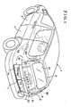
- Fig. 1 is a perspective view of a vehicle equipped with a door opening and closing apparatus for a vehicle according to an embodiment of the present invention
- Fig. 2 is a side view illustrating a schematic structure of a rear hatch including a panel actuating mechanism of a first example and also illustrating an operation locus of each of a rear hatch main body and a movable panel in a preventive control mode according to the embodiment of the present invention;
- Fig. 3 is a side view illustrating a schematic structure of the rear hatch including the panel actuating mechanism of a second example and also illustrating the operation locus of each of the rear hatch main body and the movable panel in the preventive control mode according to the embodiment of the present invention;
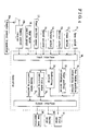
- Fig. 4 is a block diagram illustrating functions of a controller for the door opening and closing apparatus according to the embodiment of the present invention
- Fig. 5 is a diagram illustrating each positional state of the rear hatch main body and the movable panel
- Fig. 6A to 6F are schematic views illustrating positional states of the rear hatch main body and the movable panel
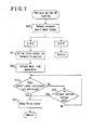
- Fig. 7 is a flowchart of a control when a retract switch is operated
- Fig. 8 is a flowchart of a control when an extend switch is operated
- Fig. 9 is a flowchart of a control when an open switch is operated.
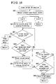
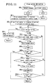
- Fig. 10 is a flowchart of a control when a close switch is operated
- Fig. 11 is a flowchart of a control when the close switch is operated according to another embodiment of the present invention.
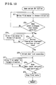
- Fig. 12 is a flowchart of a control when the open switch is operated according to still another embodiment of the present invention.
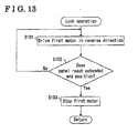
- Fig. 13 is a flowchart of a control when the rear hatch is closed according to the still another embodiment of the present invention.
- FIG. 1 is a perspective view of a vehicle equipped with a door opening and closing apparatus according to the present embodiment as viewed from an obliquely rearward direction.
- the vehicle is of a five-door type having a rear hatch 2, front side doors 3, and rear side doors 4 all of which are provided at a vehicle body 1.
- the rear hatch 2 closes an opening portion 9 that is defined by a rear pillar 5, a roof rear edge 6, and a floor rear edge 7. Loading cargo into and out of an interior of the vehicle body 1 is made possible by opening the opening portion 9.
- the rear hatch 2 includes a rear hatch main body 20 and a movable panel 30.
- the movable panel 30 moves to extend from a free end 20a of the rear hatch main body 20 (i.e., slide open operation) and to return to the free end 20a (i.e., slide close operation).
- the rear hatch main body 20, which includes a rear window 21, is attached to the vehicle body 1 so as to be pivotally rotatable between a closed position and an open position (i.e., open and close pivoting operation) by means of a horizontal hinge provided at the roof rear edge 6.
- the open and close pivoting operation of the rear hatch main body 20 is performed only by a damper 54 as illustrated in Fig.
- the rear hatch open and close driving mechanism 50 includes a second motor 51 serving as a rear hatch drive motor, an arm 52 pivotally rotating by means of the second motor 51, and a rod 53 connecting a free end of the arm 52 and the rear hatch main body 20 to each other.
- the damper 54 is also provided for the open and close pivoting operation of the rear hatch main body 20.
- the slide open and close operation of the movable panel 30 is automatically performed by a panel actuating mechanism 60 serving as an actuating mechanism provided at a void formed between an inner panel 22 and an outer panel 23 of the rear hatch main body 20.
- the panel actuating mechanism 60 according to a first example is of a reciprocating wire type as illustrated in Fig. 2 .
- a first motor 61 serving as a panel drive motor functions as a wire drive motor.
- the panel actuating mechanism 60 of the reciprocating wire type includes the first motor 61, a wire 62 wound in one direction or the other direction by means of forward or reverse rotations of the first motor 61, a roller body 63 fixed to the wire 62 and moving up and down while the wire 62 is wound in one direction or the other direction, and a guide rail 64 guiding the up and down movement of the roller body 63.
- the movable panel 30 is connected to the roller body 63 so as to move up and down in association with the movement of the roller body 63.
- the panel actuating mechanism 60 according to a second example is of a feed screw type as illustrated in Fig. 3 .
- the first motor 61 serving as the panel drive motor functions as a feed screw drive motor.
- the panel actuating mechanism 60 of the feed screw type includes the first motor 61, a feed screw 65 rotating by means of the first motor 61, a roller body 66 connected to the movable panel 30 and engaging with the feed screw 65, and the guide rail 64 guiding the up and down movement of the roller body 66.
- a door lock apparatus 81 serving as a lock portion of the rear batch main body 20 is arranged at the inner panel 22 of the rear hatch 2. Then, a striker 82 engageable with the door lock apparatus 81 is provided at a body panel of the vehicle body 1.
- a locked state (i.e., locking) and an unlocked state (i.e., unlocking) of the door lock apparatus 81 are controllable by a controller 70. That is, the door lock apparatus 81 is brought to the unlocked state by an operation of an open switch 11 so as to allow the rear hatch main body 20 to pivotally rotate to open.
- a switch detecting the locked state and the unlocked state of the door lock apparatus 81 is provided within the door lock apparatus 81.
- a detection signal of the switch is sent to the controller 70.
- a portion of the outer panel 23 of the rear hatch main body 20 is formed as an operation panel 23a.
- the open switch 11, a retract switch 13, and an extend switch 14 are provided at the operation panel 23a.
- the open switch 11 brings the rear hatch main body 20 to pivotally rotate to open from the closed state.
- the retract switch 13 brings the movable panel 30 to move from an extended position (i.e., closed position) to a retracted position (i.e., open position) where the movable panel 30 is stored within the rear hatch main body 20.
- the extend switch 14 brings the movable panel 30 to move from the retracted position to the extended position.
- a close switch 12 for bringing the rear hatch main body 20 to pivotally rotate to close from the open state is provided at each of the floor rear edge 7, the rear hatch main body 20, and a driver seat panel.
- a recess portion 7a is formed at the floor rear edge 7 so as to receive a tip end portion 30a of the movable panel 30.
- the movable panel 30 is first operated. That is, after the tip end portion 30a of the movable panel 30 disengages from the recess portion 7a, the door lock apparatus 81 is unlocked so that the rear hatch main body 20 is brought to pivotally rotate.
- the rear hatch main body 20 pivotally rotates while the tip end portion 30a of the movable panel 30 is retained at a position where the tip end portion 30a is prevented from engaging or contacting with the recess portion 7a. Afterwards, the tip end portion 30a of the movable panel 30 moves to engage with the recess portion 7a.
- the movable panel 30 is formed to extend over an entire width of the free end 20a of the rear hatch main body 20. In a state where the movable panel 30 extends from the free end 20a of the rear hatch main body 20, the movable panel 30 forms a lower half of the rear hatch 2. On the other hand, in a state where the movable panel 30 is stored within the rear hatch main body 20, the rear hatch 2 is substantially formed by only the rear hatch main body 20 when viewed from the outside. Accordingly, a length La of the rear hatch main body 20 is equal to a radius of the pivoting operation of the rear hatch 2 (i.e., pivoting operation locus of a tip end of the rear hatch 2) in cases where the movable panel 30 is stored within the rear hatch main body 20.
- a length Lmax obtained by adding a maximum extension length Lbmax of the movable panel 30 to the length La of the rear hatch main body 20 is equal to the radius of the pivoting operation of the rear hatch 2.
- a control mode in which the rear hatch main body 20 pivotally rotates to open while the movable panel 30 is shifted from the extended position to the retracted position.
- the radius of the pivoting operation locus of the tip end of the rear hatch 2 i.e., a length L
- the radius of the pivoting operation locus of the tip end of the rear hatch 2 is obtained by adding an extension length of the movable panel 30 sequentially reduced, i.e., a length Lb, to the length La of the rear hatch main body 20. That is, the pivoting operation locus of the tip end of the rear hatch 2 does not form an arc shape.
- a minimum space (i.e., horizontal length) required for the rear hatch 2 to pivotally rotate to open is equal to the length La of the rear hatch main body 20.
- operations of the rear hatch main body 20 and the movable panel 30 are controlled in such a way that a vehicle rear distance Lh that is defined as a horizontal distance between the tip end of the movable panel 30 and a pivotal point of the rear hatch main body 20 does not exceed the length La.
- the retracting operation of the movable panel 30 is desirably completed before the rear hatch main body 20 reaches an open position where the rear hatch main body 20 is horizontally arranged.
- Such control is hereinafter called a preventive control mode.
- a superior control mode of the preventive control mode provided is a basic control mode in which the rear hatch main body 20 is allowed to open after the door lock apparatus 81 is unlocked, and the movable panel 30 is allowed to move to the retracted position by means of the first motor 61.
- the basic control mode is also available when the rear hatch main body 20 is manually operated to pivotally rotate.
- An operation control of the rear hatch 2 having the aforementioned structure is performed by the controller 70 mounted within the vehicle body 1, As illustrated in Fig. 4 , the open switch 11, the close switch 12, the retract switch 13, and the extend switch 14 are all connected to the controller 70 as input devices.
- a rear hatch position sensor 16 and a panel position sensor 17 each serving as a detecting portion for detecting a position of the rear hatch main body 20 that is pivotally opened (i.e., pivotal position) are also connected to the controller 70.
- the rear hatch position sensor 16 is provided in the vicinity of a hinge 8 or within the second motor 51 for detecting the pivotal position of the rear hatch main body 20.
- the panel position sensor 17 is provided at the void between the inner panel 22 and the outer panel 23 of the rear hatch main body 20 or within the first motor 61 for detecting a moving amount of the movable panel 30. Further, according to the present embodiment, a open and close pivoting operation speed of the rear hatch main body 20 is adjustable. That is, a speed adjuster 18 manually settable is also connected to the controller 70. Furthermore, as output devices, the second motor 51 that drives the rear hatch main body 20 to pivotally rotate to open or close, the first motor 61 that drives the movable panel 30 to move to the extended position or retracted position, and the door lock apparatus 81 are connected to the controller 70.
- a remote control transmitter 19a is provided to have functions of the open switch 11, the close switch 12, the retract switch 13, the extend switch 14, and the speed adjuster 18. Then, a remote control receiver 19b is connected to the controller 70 so as to generate a signal equivalent to an input signal of each switch 11, 12, 13, or 14 in response to a signal from the remote control transmitter 19a.
- the controller 70 is substantially constituted by a microcomputer. Various functions of the controller 70 are achieved by program and/or hardware. As for functions specifically related to the present embodiment, provided are a rear hatch position calculating portion 71, a panel position calculating portion 72, a controlling portion 73, a first motor controlling portion 74, a second motor controlling portion 75, and the like.
- the rear hatch position calculating portion 71 calculates the pivotal position of the rear hatch main body 20 based on the input signal from the rear hatch position sensor 16.
- the panel position calculating portion 72 calculates a position of the movable panel 30 that is slidably operated (i.e., sliding position) based on the input signal from the panel position sensor 17.
- the control portion 73 realizes the linked operation between the rear hatch main body 20 and the movable panel 30.
- the first motor control portion 74 generates a drive signal sent to the first motor 61.
- the second motor control portion 75 generates a drive signal sent to the second motor 51.
- the control portion 73 gives a control command (i.e., control level) to each of the first motor control portion 74 and the second motor control portion 75, by following a predetermined algorithm, based on the input signal from each of the open switch 11, the close switch 12, the retract switch 13, the extend switch 14, and the speed adjuster 18, and based on the position of each of the rear hatch main body 20 and the movable panel 30, which will be explained later in detail.
- a control command i.e., control level
- the rear hatch open and close driving mechanism 50 and the panel actuating mechanism 60 are individually operative.
- the rear hatch 2 can be in various positional states depending on the pivotal position of the rear hatch main body 20 and the sliding position of the movable panel 30.
- the various positional states of the rear hatch 2 are classified into such a manner as illustrated in a table of Fig. 5 .
- the positional states classified are schematically illustrated in Figs. 6A to 6F . Specifically, as illustrated in Fig.
- the positional states of the rear hatch may body 20 are classified into a state where the rear hatch main body 20 is driven to pivotally rotate to the closed position (i.e., closed state), a state where the rear hatch main body 20 is driven to pivotally rotate to the fully open position (i.e., open state), and a state where the rear hatch main body 20 is not in the closed position or the fully open position (i.e., half-open state).
- the positional states of the movable panel 30 are classified into a state where the movable panel 30 extends until the tip end portion 30a of the movable panel 30 enters within the recess portion 7a (i.e., closed state), a state where the movable panel 30 fully moves to the retracted position (i.e., open state), a state where the movable panel 30 is not in the extended position or the retracted position (i.e., half-open state).
- a state A in Fig. 6A illustrates a state where the movable panel 30 is in the closed state while the rear hatch main body 20 is in the closed state.
- FIG. 6B illustrates a state where the movable panel 30 is in the half-open state while the rear hatch main body 20 is in the closed state.
- a state C in Fig. 6C illustrates a state where the movable panel 30 is in the open state while the rear hatch main body 20 is in the closed state.
- a state D in Fig. 6D illustrates a state where the movable panel 30 is in the half-open state while the rear hatch main body 20 is in the half-open state.
- a state E in Fig. 6E illustrates a state where the movable panel 30 is in the open state while the rear hatch main body 20 is in the half open state.
- FIG. 6F illustrates a state where the movable panel 30 is in the open state while the rear hatch main body 20 is in the open state.
- the rear hatch main body 20 is never driven to pivotally rotate while the movable panel 30 is in the closed position.
- a state where the rear hatch main body 20 is in the half-open or open state with the movable panel 30 in the closed state does not exist.
- the movable panel 30 is retracted before the rear hatch main body 20 is driven to pivotally rotate to the fully open position, a state where the movable panel 30 is in the half-open state with the rear hatch main body 20 in the open state does not exist.
- the rear hatch main body 20 is driven to pivotally rotate by an operation of the open switch 11 or the close switch 12.
- the movable panel 30 is driven to slidably move by an operation of the retract switch 13 or the extend switch 14. In this case, however, a control procedure is different depending on the aforementioned positional states of the rear hatch main body 20 and the movable panel 30 before the operation of each switch. Next, a control flow upon operation of each switch will be explained.
- the control portion 73 detects the present positional state (i.e., aforementioned states A to F) of the rear hatch 2 based on input signals from various sensors in step 10.
- the movable panel 30 In the state C, E, or F, the movable panel 30 is already completely retracted and thus the present routine is terminated without any action.
- the movable panel 30 In the state A, B, or D, the movable panel 30 extends to some degree from the retracted position.
- the first motor 61 is driven in a forward direction to move (i.e., to raise) the movable panel 30 in a retracting direction in step 11 (i.e., retracting operation).
- the locked state between the rear hatch main body 20 and the vehicle body 1 is released by unlocking the door lock apparatus 81 in step 12 (i.e., unlock operation). That is, in association with the turning on of the retract switch 13, the unlock operation by the door lock apparatus 81 serving as the lock portion between the rear hatch main body 20 and the vehicle body 1 and the retracting operation by the movable panel 30 are automatically, i.e., simultaneously, performed at the same time. Then, it is determined whether or not the movable panel 30 reaches a retracted end position in step 13. When it is determined that the movable panel 30 reaches the retracted end position, the driving of the first motor 61 is stopped in step 14 to thereby terminate the present routine.
- the door lock apparatus 81 is unlocked when the movable panel 30 starts moving in the retracting direction in step 11.
- the door lock apparatus 81 may be unlocked after the movable panel 30 reaches the retracted end position. Consequently, the opening of the rear hatch 2 without the movable panel 30 to be retracted can be forcedly avoided.
- the opening portion 9 can be partially opened relative to the vehicle body 1 by the operation of the retract switch 13 in the state A as a lower area of the rear hatch 2 is opened by a certain height without opening the rear hatch main body 20. Small luggage or small animals can be taken in and out through the opening portion 9, accordingly.
- step 15 it is further determined whether or not the retract switch 13 is turned off in step 15. In cases where it is determined that the retract switch 13 is not yet turned off, the process returns to step 13 so as to continue raising the movable panel 30. In cases where the retract switch 13 is turned on, the driving of the first motor 61 is stopped in step 14 to thereby cancel the movement of the movable panel 30.
- the driving of the first motor 61 is stopped in step 23 so as to terminate the present routine.
- the process returns to step 22 so as to continue the reverse driving of the first motor 61 and to continue lowering the movable panel 30.
- the driving of the first motor 61 is stopped in step 23 to thereby cancel the movement of the movable panel 30.
- the control procedure in a state where the open switch 11 is turned on will be explained with reference to Fig. 9 .
- the control portion 73 detects the present positional state (i.e., aforementioned states A to F) of the rear hatch 2 based on input signals from various sensors in step 30.
- the state A the rear hatch 2 is completely closed.
- the first motor 61 is driven in the forward direction in step 31.
- the driving of the first motor 61 is stopped in step 33 so as to terminate the present routine.
- step 34 the control portion 73 determines the disengagement of the movable panel 30 from the recess portion 7a based on the sliding position of the movable panel 30, or the driving time or position of the first motor 61. Then, the door lock apparatus 81 is unlocked in step 34a.
- the control portion 73 selects the aforementioned preventive control mode so that the movable panel 30 is completely retracted before the rear hatch main body 20 reaches the open position where the rear hatch main body 20 is horizontally positioned, and that the rear hatch 2 including the movable panel 30 can pivotally rotate to open within a space necessary for the pivoting open operation of the rear hatch main body 20. Accordingly, the control portion 73 sends a control signal to the first motor control portion 74 and the second motor control portion 75 so as to achieve the linked operation between the rear hatch main body 20 and the movable panel 30.
- the first motor 61 is driven in the forward direction in the preventive control mode based on a drive signal from the first motor control portion 74 in step 35.
- the second motor 51 is driven in the forward direction in the preventive control mode based on a drive signal from the second motor control portion 75 in step 36.
- step 37 it is determined whether or not the movable panel 30 reaches the retracted end position in step 37.
- the open switch 11 is turned off in step 39.
- the process returns to step 37 so as to continue the pivoting open operation of the rear hatch main body 20 and the slide open operation of the movable panel 30.
- the driving of each of the second motor 51 and the first motor 61 is stopped in step 40 so as to cancel the open operation of the rear hatch 2, The present routine is terminated accordingly.
- the first motor 61 is stopped in step 38.
- the second motor 51 is stopped in step 42 to thereby terminate the present routine.
- the process returns to step 41 so as to continue the pivoting open operation of the rear hatch main body 20.
- the driving of the second motor 51 is stopped in step 42 so that the open operation of the rear hatch main body 20 is cancelled. The present routine is terminated accordingly.
- step 30 In cases where the state B is detected in step 30 where the present positional state of the rear hatch 2 is detected, the aforementioned steps 31 to 34 are omitted since the movable panel 30 is already in the half-open state.
- the first motor 61 and the second motor 51 are each started to be driven in the forward direction in the preventive control mode in step 35 and step 36 after the unlocking of the door lock apparatus 81 in step 34a.
- the rear hatch main body 20 is in the half-open state and thus the door lock apparatus 81 is in the unlocked state.
- the forward driving of each of the first motor 61 and the second motor 51 is started in the preventive control mode in step 35 and step 36.
- step 30 In cases where the state C is detected in step 30, the movable panel 30 is already in the open state (i.e., fully retracted position). Thus, the aforementioned steps 31 to 34 and step 35 in which the first motor 61 is driven in the forward direction in the preventive control mode are omitted. After the door lock apparatus 81 is unlocked in step 34a, the forward driving of the second motor 51 is started in the preventive control mode in step 36.
- the appropriate operation of the open switch 11 allows to open the rear batch 2 including the movable panel 30 and to stop the rear hatch 2 at an arbitrary angle within the space for the pivoting rotation of only the rear hatch main body 20.
- the control procedure in a state where the close switch 12 is turned on will be explained with reference to Fig. 10 .
- the close switch 12 When the close switch 12 is turned on, the present positional state (i.e., aforementioned states A to F) of the rear hatch 2 is detected in step 50. In cases where the state A, B or C is detected, the rear hatch main body 20 is already in the closed position and thus the present routine is terminated without any action.
- step 50 In cases where the state D, E, or F is detected in step 50, the movable panel 30 and the rear hatch main body 20 are both in the half-open or closed position.
- the second motor 51 is driven in the reverse direction in step 51, The driving of the second motor 51 is continued until the rear hatch main body 20 pivotally downwardly rotates to a close end position. In this case, it is determined whether or not the close switch 12 is turned off in step 57. When it is determined that the close switch 12 is turned off, the driving of the second motor 51 is stopped in step 58 so as to terminate the present routine. Unless the close switch 12 is turned off, the pivotal position of the rear hatch main body 20 is checked or determined.
- step 59 When it is determined that the rear hatch main body 20 reaches the close end position in step 59, the driving of the second motor 51 is stopped so that the operation of the rear hatch main body 20 is stopped in step 60. Accordingly, the rear hatch main body 20 and the movable panel 30 are brought to the state C.
- the first motor 61 is driven in the reverse direction in the basic control mode in step 61 so that the tip end portion 30a of the movable panel 30 is fully inserted into the recess portion 7a to thereby achieve the fully closed state of the rear hatch 2.
- step 62 it is determined whether or not the close switch 12 is turned off in step 62.
- the driving of the first motor 61 is stopped in step 64 so as to terminate the present routine.
- the operation of the movable panel 30 in the downward direction i.e., extending operation
- the driving of the first motor 61 is stopped in step 64 so as to terminate the present routine.
- the pivotally rotational speed of the rear hatch main body 20 is changeable by means of an operation of the speed adjuster 18.
- the controlling portion 73 switches tables for reading control values sent to the first motor controlling portion 74 and the second motor controlling portion 75, with parameters of the pivotal position of the rear hatch main body 20 and the sliding position of the movable panel 30.
- the control values for operating the rear hatch main body 20 and the movable panel 30 in the preventive control mode in response to the pivotally rotational speed of the rear hatch main body 20 are recorded.
- the recess portion 7a into which the tip end portion 30a is inserted is provided at the floor end portion 7b.
- the interference between the tip end portion 30a of the movable panel 30 and the recess portion 7a should be avoided in the pivoting operation of the rear hatch main body 20.
- the operation of the rear hatch main body 20 may be further simplified. For example, in the control procedure for the open switch to be turned on, steps 31 to 34 for disengaging the tip end portion 30a of the movable panel 30 from the recess portion 7a in Fig. 9 can be omitted.
- the close switch 12 to be turned on which is illustrated in Fig.
- each of the second motor 51 and the first motor 61 is driven in the reverse direction in the preventive control mode in steps 51 and 52, respectively. Then, it is determined whether or not the close switch is turned off in step 57, whether or not the rear hatch main body 20 reaches the close end position in step 59, and whether or not the movable panel 30 reaches the extended end position in step 63.
- the close switch is turned off, the driving of each of the second motor 51 and the first motor 61 is stopped in step 58 so as to terminate the present routine.
- the driving of the second motor 51 is stopped in step 60. Then, 1 (one) is assigned to a flag 1_flag in step 60a.
- Step 64 When it is determined that the movable panel 30 reaches the extended end position in step 63, the driving of the first motor 61 is stopped in step 64. Then, 1 (one) is assigned to a flag 2_flag in step 64a. Steps 60b and 64b in which it is determined whether or not both of the flag 1_flag and the flag 2_flag are assigned by one are provided to terminate the present routine when both of the second motor 51 and the first motor 61 are stopped, i.e., the rear hatch 2 is completely closed.
- the movable panel 30 may not be fully retracted into the free end 20a of the rear hatch main body 20 by the time the rear hatch main body 20 reaches the open position where the rear hatch main body 20 is horizontally arranged.
- the decrease in the drive voltage of the first motor 61 may induce the decrease in the rotational speed of the first motor 61.
- the rear hatch 2 may interfere with an object positioned in the rear of the vehicle in a state where the rear hatch 2 is in the open position at which the rear hatch main body 20 is horizontally positioned.
- the open operation of the rear hatch 2 is performed on the basis of a flow illustrated in Fig. 12 as still another embodiment. That is, after the open switch 11 is turned on, the first motor 61 is driven in the forward direction in step 71. It is determined whether or not the tip end portion 30a of the movable panel 30 disengages from the recess portion 7a in step 72.
- retract completion time Ta a time from the disengagement of the movable panel 30 from the recess portion 7a to the completion of retraction into the free end 20a (i.e., retract completion time Ta) is calculated on the basis of the detected rotational speed of the first motor 61. Further, in step 73, the calculated retract completion time Ta is compared with a time for the rear hatch main body 20 to move from the closed position to the open position (open position arrival time Tb) that is estimated and stored beforehand by the control portion.
- the unlocking of the door lock apparatus 81 is not performed.
- the first motor 61 is driven in the forward direction so as to move the movable panel 30 in step 74.
- the position of the movable panel 30 and the latest retract completion time at that time are calculated at a predetermined timing.
- the door lock apparatus 81 is unlocked in step 75.
- the rear hatch main body 20 is operated to open by means of the damper 54, and it is determined whether or not the movable panel 30 is completely retracted in step 76.
- the forward driving of the first motor 61 is continued in step 77.
- the first motor 61 is stopped in step 78 so as to terminate the present routine.
- the rear hatch main body 20 is closed by hand against the extension force of the damper 54 and a lock operation is performed on the basis of a flow illustrated in Fig. 13 . That is, the first motor 61 is driven in the reverse direction in step 101, which is continued unless the movable panel 30 reaches the extended end position in step 102.
- the driving of the first motor 61 is stopped in step 103 so as to terminate the present routine.
- the door opening and closing apparatus is used for the rear hatch of the vehicle.
- the door opening and closing apparatus may be used for a multi-stage pivotally opening and closing door unit of a truck or other means than the vehicle.
- a door opening and closing apparatus for a vehicle for opening and closing a rear hatch (2) including a rear hatch main body (20) and a movable panel (30) the door opening and closing apparatus includes a lock portion (81) provided between the rear hatch main body and the movable panel, an actuating mechanism (60) provided between the rear hatch main body (20) and the movable panel (30) and causing the movable panel to move between a retracted position and an extended position, a controller (70) connected to the lock portion (81) and the actuating mechanism (60) and controlling the lock portion and the actuating mechanism so that the lock portion is unlocked and the movable panel (30) moves towards the retracted position, and a switch (11,12,13,14) connected to the controller and serving as a trigger for controlling the lock
Landscapes
- Engineering & Computer Science (AREA)
- Mechanical Engineering (AREA)
- Power-Operated Mechanisms For Wings (AREA)
- Lock And Its Accessories (AREA)
Abstract
Description
- This invention generally relates to a door opening and closing apparatus for a vehicle. More particularly, this invention pertains to a door opening and closing apparatus for opening and closing a door such as a rear hatch provided in the rear of a vehicle.
- A known rear hatch includes an opening and closing member (i.e., rear hatch main body) that is hinged at the rear top of a vehicle body (i.e., supporting point) and opens upward, and a movable panel movable in upward and downward directions and accommodated within the opening and closing member when the rear hatch opens upward. Such rear hatch is disclosed in
JP6008033U - According to the aforementioned rear hatch, a switch operation for unlocking and opening the opening and closing member is not linked to a switch operation for raising the movable panel, which leads to a complicated opening operation of the rear hatch. In addition, in cases where opening of the opening and closing member and raising of the movable panel are both performed, the opening and closing member is opened after the movable panel is completely raised, which requires a certain amount of time. A need thus exists for a door opening and closing apparatus for a vehicle that can realize an effective linkage operation between an unlocking of a rear hatch main body and an opening of a movable panel.
- According to an aspect of the present invention, a door opening and closing apparatus for a vehicle for opening and closing a rear hatch including a rear hatch main body and a movable panel, the rear hatch main body adapted to be provided in a rear portion of a vehicle body so as to pivotally rotate between a closed position and an open position, the movable panel slidably movable relative to a free end of the rear hatch main body, the door opening and closing apparatus includes a lock portion provided between the rear hatch main body and the movable panel the lock portion being locked for locking the rear hatch main body with the vehicle body, the lock portion being unlocked for allowing the rear hatch main body to open, an actuating mechanism provided between the rear hatch main body and the movable panel and causing the movable panel to move between a retracted position and an extended position, a controller connected to the lock portion and the actuating mechanism and controlling the lock portion and the actuating mechanism so that the lock portion is unlocked and the movable panel moves towards the retracted position, and a switch connected to the controller and serving as a trigger for controlling the lock portion and the actuating mechanism by means of the controller.
- According to the aforementioned invention, the unlock operation of the lock portion and the retracting operation of the movable panel are automatically, i.e., simultaneously, operated by means of the switch operation. That is, the unlock operation of the lock operation and the retracting operation of the movable panel are performed by one switch operation to thereby simplify the operation of the rear hatch.
- In addition, the controller controls the lock portion and the actuating mechanism so that the movable panel moves to the retracted position before the lock portion is unlocked.
- Thus, the rear hatch main body is prevented from being opened without the movable panel to be retracted.
- Further, the opening and closing apparatus includes a detecting portion connected to the controller and detecting that the rear hatch main body reaches the open position, wherein the controller controls a retracting operation of the movable panel on the basis that the detecting portion detects the open position of the rear hatch main body.
- Therefore, the retracting operation of the movable panel and the opening operation of the rear hatch main body can be performed at the same time.
- Furthermore, the controller finishes controlling the retracting operation of the movable panel at a time the rear hatch main body reaches the open position.
- Thus, the vehicle can be parked with a minimum vehicle rear distance.
- Furthermore, the actuating mechanism includes an electric motor serving as a drive source, the controller calculating a retract completion time for the movable panel to reach the retracted position based on a rotational speed of the electric motor, and comparing the calculated retract completion time with an open position arrival time estimated beforehand for the rear hatch main body to reach the open position from the closed position for controlling a locking or unlocking of the lock portion.
- Thus, at a time of the rear hatch in the open state, the interference between the rear hatch and an object in the rear of the vehicle can be prevented.
- The foregoing and additional features and characteristics of the present invention will become more apparent from the following detailed description considered with reference to the accompanying drawings, wherein:
-
Fig. 1 is a perspective view of a vehicle equipped with a door opening and closing apparatus for a vehicle according to an embodiment of the present invention; -
Fig. 2 is a side view illustrating a schematic structure of a rear hatch including a panel actuating mechanism of a first example and also illustrating an operation locus of each of a rear hatch main body and a movable panel in a preventive control mode according to the embodiment of the present invention; -
Fig. 3 is a side view illustrating a schematic structure of the rear hatch including the panel actuating mechanism of a second example and also illustrating the operation locus of each of the rear hatch main body and the movable panel in the preventive control mode according to the embodiment of the present invention; -
Fig. 4 is a block diagram illustrating functions of a controller for the door opening and closing apparatus according to the embodiment of the present invention; -
Fig. 5 is a diagram illustrating each positional state of the rear hatch main body and the movable panel; -
Fig. 6A to 6F are schematic views illustrating positional states of the rear hatch main body and the movable panel; -
Fig. 7 is a flowchart of a control when a retract switch is operated; -
Fig. 8 is a flowchart of a control when an extend switch is operated; -
Fig. 9 is a flowchart of a control when an open switch is operated; -
Fig. 10 is a flowchart of a control when a close switch is operated; -
Fig. 11 is a flowchart of a control when the close switch is operated according to another embodiment of the present invention; -
Fig. 12 is a flowchart of a control when the open switch is operated according to still another embodiment of the present invention; and -
Fig. 13 is a flowchart of a control when the rear hatch is closed according to the still another embodiment of the present invention. - An embodiment of the present invention will be explained with reference to the attached drawings.
Fig. 1 is a perspective view of a vehicle equipped with a door opening and closing apparatus according to the present embodiment as viewed from an obliquely rearward direction. The vehicle is of a five-door type having arear hatch 2, front side doors 3, and rear side doors 4 all of which are provided at avehicle body 1. Therear hatch 2 closes an opening portion 9 that is defined by a rear pillar 5, a roof rear edge 6, and a floorrear edge 7. Loading cargo into and out of an interior of thevehicle body 1 is made possible by opening the opening portion 9. - As seen from
Figs. 2 and3 , therear hatch 2 includes a rear hatchmain body 20 and amovable panel 30. Themovable panel 30 moves to extend from afree end 20a of the rear hatch main body 20 (i.e., slide open operation) and to return to thefree end 20a (i.e., slide close operation). The rear hatchmain body 20, which includes arear window 21, is attached to thevehicle body 1 so as to be pivotally rotatable between a closed position and an open position (i.e., open and close pivoting operation) by means of a horizontal hinge provided at the roof rear edge 6. The open and close pivoting operation of the rear hatchmain body 20 is performed only by adamper 54 as illustrated inFig. 2 or is automatically performed by a rear hatch open andclose driving mechanism 50 as illustrated inFig. 3 . The rear hatch open andclose driving mechanism 50 includes asecond motor 51 serving as a rear hatch drive motor, an arm 52 pivotally rotating by means of thesecond motor 51, and a rod 53 connecting a free end of the arm 52 and the rear hatchmain body 20 to each other. In addition, thedamper 54 is also provided for the open and close pivoting operation of the rear hatchmain body 20. - The slide open and close operation of the
movable panel 30 is automatically performed by apanel actuating mechanism 60 serving as an actuating mechanism provided at a void formed between aninner panel 22 and anouter panel 23 of the rear hatchmain body 20. Thepanel actuating mechanism 60 according to a first example is of a reciprocating wire type as illustrated inFig. 2 . Afirst motor 61 serving as a panel drive motor functions as a wire drive motor. Thus, thepanel actuating mechanism 60 of the reciprocating wire type includes thefirst motor 61, awire 62 wound in one direction or the other direction by means of forward or reverse rotations of thefirst motor 61, aroller body 63 fixed to thewire 62 and moving up and down while thewire 62 is wound in one direction or the other direction, and a guide rail 64 guiding the up and down movement of theroller body 63. Themovable panel 30 is connected to theroller body 63 so as to move up and down in association with the movement of theroller body 63. Thepanel actuating mechanism 60 according to a second example is of a feed screw type as illustrated inFig. 3 . Thefirst motor 61 serving as the panel drive motor functions as a feed screw drive motor. Thus, thepanel actuating mechanism 60 of the feed screw type includes thefirst motor 61, afeed screw 65 rotating by means of thefirst motor 61, aroller body 66 connected to themovable panel 30 and engaging with thefeed screw 65, and the guide rail 64 guiding the up and down movement of theroller body 66. - In order to retain the closed state of the rear hatch
main body 20, adoor lock apparatus 81 serving as a lock portion of the rear batchmain body 20 is arranged at theinner panel 22 of therear hatch 2. Then, astriker 82 engageable with thedoor lock apparatus 81 is provided at a body panel of thevehicle body 1. A locked state (i.e., locking) and an unlocked state (i.e., unlocking) of thedoor lock apparatus 81 are controllable by acontroller 70. That is, thedoor lock apparatus 81 is brought to the unlocked state by an operation of anopen switch 11 so as to allow the rear hatchmain body 20 to pivotally rotate to open. In addition, a switch detecting the locked state and the unlocked state of thedoor lock apparatus 81 is provided within thedoor lock apparatus 81. A detection signal of the switch is sent to thecontroller 70. A portion of theouter panel 23 of the rear hatchmain body 20 is formed as anoperation panel 23a. Theopen switch 11, a retractswitch 13, and an extendswitch 14 are provided at theoperation panel 23a. Theopen switch 11 brings the rear hatchmain body 20 to pivotally rotate to open from the closed state. The retractswitch 13 brings themovable panel 30 to move from an extended position (i.e., closed position) to a retracted position (i.e., open position) where themovable panel 30 is stored within the rear hatchmain body 20. The extendswitch 14 brings themovable panel 30 to move from the retracted position to the extended position. Aclose switch 12 for bringing the rear hatchmain body 20 to pivotally rotate to close from the open state is provided at each of the floorrear edge 7, the rear hatchmain body 20, and a driver seat panel. - According to the present embodiment, in order to enhance the sealing performance between the
movable panel 30 and the floorrear edge 7, arecess portion 7a is formed at the floorrear edge 7 so as to receive atip end portion 30a of themovable panel 30. In such structure, in cases where therear hatch 2 is brought to pivotally rotate to open from the closed state, themovable panel 30 is first operated. That is, after thetip end portion 30a of themovable panel 30 disengages from therecess portion 7a, thedoor lock apparatus 81 is unlocked so that the rear hatchmain body 20 is brought to pivotally rotate. In addition, in cases where therear hatch 2 is brought to pivotally rotate to close from the open state, the rear hatchmain body 20 pivotally rotates while thetip end portion 30a of themovable panel 30 is retained at a position where thetip end portion 30a is prevented from engaging or contacting with therecess portion 7a. Afterwards, thetip end portion 30a of themovable panel 30 moves to engage with therecess portion 7a. - The
movable panel 30 is formed to extend over an entire width of thefree end 20a of the rear hatchmain body 20. In a state where themovable panel 30 extends from thefree end 20a of the rear hatchmain body 20, themovable panel 30 forms a lower half of therear hatch 2. On the other hand, in a state where themovable panel 30 is stored within the rear hatchmain body 20, therear hatch 2 is substantially formed by only the rear hatchmain body 20 when viewed from the outside. Accordingly, a length La of the rear hatchmain body 20 is equal to a radius of the pivoting operation of the rear hatch 2 (i.e., pivoting operation locus of a tip end of the rear hatch 2) in cases where themovable panel 30 is stored within the rear hatchmain body 20. On the other hand, in cases where themovable panel 30 extends at a maximum from thefree end 20a of the rear hatchmain body 20, a length Lmax obtained by adding a maximum extension length Lbmax of themovable panel 30 to the length La of the rear hatchmain body 20 is equal to the radius of the pivoting operation of therear hatch 2. - According to the door opening and closing apparatus of the present embodiment, provided is a control mode in which the rear hatch
main body 20 pivotally rotates to open while themovable panel 30 is shifted from the extended position to the retracted position. Thus, the radius of the pivoting operation locus of the tip end of therear hatch 2, i.e., a length L, is obtained by adding an extension length of themovable panel 30 sequentially reduced, i.e., a length Lb, to the length La of the rear hatchmain body 20. That is, the pivoting operation locus of the tip end of therear hatch 2 does not form an arc shape. In cases where an upright object is present in the rear of the vehicle, a minimum space (i.e., horizontal length) required for therear hatch 2 to pivotally rotate to open is equal to the length La of the rear hatchmain body 20. In order to bring therear hatch 2 to pivotally rotate within the minimum space while the rear hatchmain body 20 and themovable panel 30 are simultaneously operated, operations of the rear hatchmain body 20 and themovable panel 30 are controlled in such a way that a vehicle rear distance Lh that is defined as a horizontal distance between the tip end of themovable panel 30 and a pivotal point of the rear hatchmain body 20 does not exceed the length La. In order to bring therear hatch 2 to pivotally rotate within a narrow or limited space, the retracting operation of themovable panel 30 is desirably completed before the rear hatchmain body 20 reaches an open position where the rear hatchmain body 20 is horizontally arranged. Such control is hereinafter called a preventive control mode. As a superior control mode of the preventive control mode, provided is a basic control mode in which the rear hatchmain body 20 is allowed to open after thedoor lock apparatus 81 is unlocked, and themovable panel 30 is allowed to move to the retracted position by means of thefirst motor 61. The basic control mode is also available when the rear hatchmain body 20 is manually operated to pivotally rotate. - An operation control of the
rear hatch 2 having the aforementioned structure is performed by thecontroller 70 mounted within thevehicle body 1, As illustrated inFig. 4 , theopen switch 11, theclose switch 12, the retractswitch 13, and the extendswitch 14 are all connected to thecontroller 70 as input devices. In order to precisely perform operations of the rear hatchmain body 20 and themovable panel 30 in the basic control mode or the preventive control mode, a rearhatch position sensor 16 and apanel position sensor 17 each serving as a detecting portion for detecting a position of the rear hatchmain body 20 that is pivotally opened (i.e., pivotal position) are also connected to thecontroller 70. The rearhatch position sensor 16 is provided in the vicinity of a hinge 8 or within thesecond motor 51 for detecting the pivotal position of the rear hatchmain body 20. Thepanel position sensor 17 is provided at the void between theinner panel 22 and theouter panel 23 of the rear hatchmain body 20 or within thefirst motor 61 for detecting a moving amount of themovable panel 30. Further, according to the present embodiment, a open and close pivoting operation speed of the rear hatchmain body 20 is adjustable. That is, aspeed adjuster 18 manually settable is also connected to thecontroller 70. Furthermore, as output devices, thesecond motor 51 that drives the rear hatchmain body 20 to pivotally rotate to open or close, thefirst motor 61 that drives themovable panel 30 to move to the extended position or retracted position, and thedoor lock apparatus 81 are connected to thecontroller 70. - In order to cause the
rear hatch 2 to open and close at a distance from the vehicle, aremote control transmitter 19a is provided to have functions of theopen switch 11, theclose switch 12, the retractswitch 13, the extendswitch 14, and thespeed adjuster 18. Then, aremote control receiver 19b is connected to thecontroller 70 so as to generate a signal equivalent to an input signal of eachswitch remote control transmitter 19a. - The
controller 70 is substantially constituted by a microcomputer. Various functions of thecontroller 70 are achieved by program and/or hardware. As for functions specifically related to the present embodiment, provided are a rear hatchposition calculating portion 71, a panelposition calculating portion 72, a controllingportion 73, a firstmotor controlling portion 74, a secondmotor controlling portion 75, and the like. The rear hatchposition calculating portion 71 calculates the pivotal position of the rear hatchmain body 20 based on the input signal from the rearhatch position sensor 16. The panelposition calculating portion 72 calculates a position of themovable panel 30 that is slidably operated (i.e., sliding position) based on the input signal from thepanel position sensor 17. Thecontrol portion 73 realizes the linked operation between the rear hatchmain body 20 and themovable panel 30. The firstmotor control portion 74 generates a drive signal sent to thefirst motor 61. The secondmotor control portion 75 generates a drive signal sent to thesecond motor 51. - The
control portion 73 gives a control command (i.e., control level) to each of the firstmotor control portion 74 and the secondmotor control portion 75, by following a predetermined algorithm, based on the input signal from each of theopen switch 11, theclose switch 12, the retractswitch 13, the extendswitch 14, and thespeed adjuster 18, and based on the position of each of the rear hatchmain body 20 and themovable panel 30, which will be explained later in detail. - According to the aforementioned door opening and closing apparatus, the rear hatch open and
close driving mechanism 50 and thepanel actuating mechanism 60 are individually operative. Thus, therear hatch 2 can be in various positional states depending on the pivotal position of the rear hatchmain body 20 and the sliding position of themovable panel 30. The various positional states of therear hatch 2 are classified into such a manner as illustrated in a table ofFig. 5 . In addition, the positional states classified are schematically illustrated inFigs. 6A to 6F . Specifically, as illustrated inFig. 5 , the positional states of the rear hatch maybody 20 are classified into a state where the rear hatchmain body 20 is driven to pivotally rotate to the closed position (i.e., closed state), a state where the rear hatchmain body 20 is driven to pivotally rotate to the fully open position (i.e., open state), and a state where the rear hatchmain body 20 is not in the closed position or the fully open position (i.e., half-open state). The positional states of themovable panel 30 are classified into a state where themovable panel 30 extends until thetip end portion 30a of themovable panel 30 enters within therecess portion 7a (i.e., closed state), a state where themovable panel 30 fully moves to the retracted position (i.e., open state), a state where themovable panel 30 is not in the extended position or the retracted position (i.e., half-open state). Then, a state A inFig. 6A illustrates a state where themovable panel 30 is in the closed state while the rear hatchmain body 20 is in the closed state. A state B inFig. 6B illustrates a state where themovable panel 30 is in the half-open state while the rear hatchmain body 20 is in the closed state. A state C inFig. 6C illustrates a state where themovable panel 30 is in the open state while the rear hatchmain body 20 is in the closed state. Further, a state D inFig. 6D illustrates a state where themovable panel 30 is in the half-open state while the rear hatchmain body 20 is in the half-open state. A state E inFig. 6E illustrates a state where themovable panel 30 is in the open state while the rear hatchmain body 20 is in the half open state. A state F inFig. 6F illustrates a state where themovable panel 30 is in the open state while the rear hatchmain body 20 is in the open state. According to the present embodiment, the rear hatchmain body 20 is never driven to pivotally rotate while themovable panel 30 is in the closed position. Thus, a state where the rear hatchmain body 20 is in the half-open or open state with themovable panel 30 in the closed state does not exist. In the same way, since themovable panel 30 is retracted before the rear hatchmain body 20 is driven to pivotally rotate to the fully open position, a state where themovable panel 30 is in the half-open state with the rear hatchmain body 20 in the open state does not exist. - The rear hatch
main body 20 is driven to pivotally rotate by an operation of theopen switch 11 or theclose switch 12. Themovable panel 30 is driven to slidably move by an operation of the retractswitch 13 or the extendswitch 14. In this case, however, a control procedure is different depending on the aforementioned positional states of the rear hatchmain body 20 and themovable panel 30 before the operation of each switch. Next, a control flow upon operation of each switch will be explained. - The control procedure in a state where the retract
switch 13 is turned on will be explained with reference toFig. 7 . When the retractswitch 13 is turned on, thecontrol portion 73 detects the present positional state (i.e., aforementioned states A to F) of therear hatch 2 based on input signals from various sensors instep 10. In the state C, E, or F, themovable panel 30 is already completely retracted and thus the present routine is terminated without any action. In the state A, B, or D, themovable panel 30 extends to some degree from the retracted position. Thus, thefirst motor 61 is driven in a forward direction to move (i.e., to raise) themovable panel 30 in a retracting direction in step 11 (i.e., retracting operation). Further, the locked state between the rear hatchmain body 20 and thevehicle body 1 is released by unlocking thedoor lock apparatus 81 in step 12 (i.e., unlock operation). That is, in association with the turning on of the retractswitch 13, the unlock operation by thedoor lock apparatus 81 serving as the lock portion between the rear hatchmain body 20 and thevehicle body 1 and the retracting operation by themovable panel 30 are automatically, i.e., simultaneously, performed at the same time. Then, it is determined whether or not themovable panel 30 reaches a retracted end position instep 13. When it is determined that themovable panel 30 reaches the retracted end position, the driving of thefirst motor 61 is stopped instep 14 to thereby terminate the present routine. According to the present embodiment, thedoor lock apparatus 81 is unlocked when themovable panel 30 starts moving in the retracting direction instep 11. Alternatively, thedoor lock apparatus 81 may be unlocked after themovable panel 30 reaches the retracted end position. Consequently, the opening of therear hatch 2 without themovable panel 30 to be retracted can be forcedly avoided. Specifically, the opening portion 9 can be partially opened relative to thevehicle body 1 by the operation of the retractswitch 13 in the state A as a lower area of therear hatch 2 is opened by a certain height without opening the rear hatchmain body 20. Small luggage or small animals can be taken in and out through the opening portion 9, accordingly. Unless themovable panel 30 reaches the retracted end position, it is further determined whether or not the retractswitch 13 is turned off instep 15. In cases where it is determined that the retractswitch 13 is not yet turned off, the process returns to step 13 so as to continue raising themovable panel 30. In cases where the retractswitch 13 is turned on, the driving of thefirst motor 61 is stopped instep 14 to thereby cancel the movement of themovable panel 30. - The control procedure in a state where the extend
switch 14 is turned on will be explained with reference toFig. 8 . When the extendswitch 14 is turned on, the present positional state of therear hatch 2 is detected instep 20. In the state A, themovable panel 30 reaches an extended end position as already completely extended. Thus, the present routine is terminated without any action. In the state B, D, E, F, or C, themovable panel 30 is retracted to some degree from the extended end position. Thus, thefirst motor 61 is driven in a reverse direction to move (i.e., lower) themovable panel 30 in the extending direction instep 21. It is determined whether or not themovable panel 30 reaches the extended end position instep 22. When it is determined that themovable panel 30 reaches the extended end position, the driving of thefirst motor 61 is stopped instep 23 so as to terminate the present routine. Unless themovable panel 30 reaches the extended end position, it is determined whether or not the extendswitch 14 is turned off. In cases where it is determined that the extendswitch 14 is not yet turned off instep 24, the process returns to step 22 so as to continue the reverse driving of thefirst motor 61 and to continue lowering themovable panel 30. In cases where it is determined that the extendswitch 14 is turned off instep 24, the driving of thefirst motor 61 is stopped instep 23 to thereby cancel the movement of themovable panel 30. - The control procedure in a state where the
open switch 11 is turned on will be explained with reference toFig. 9 . When theopen switch 11 is turned on, thecontrol portion 73 detects the present positional state (i.e., aforementioned states A to F) of therear hatch 2 based on input signals from various sensors instep 30. In the state A, therear hatch 2 is completely closed. Thus, in order to disengage themovable panel 30 from therecess portion 7a, thefirst motor 61 is driven in the forward direction in step 31. When it is determined that theopen switch 11 is turned off instep 32, the driving of thefirst motor 61 is stopped instep 33 so as to terminate the present routine. Unless theopen switch 11 is turned off, the forward driving of thefirst motor 61 is continued until themovable panel 30 disengages from therecess portion 7a. Instep 34, thecontrol portion 73 determines the disengagement of themovable panel 30 from therecess portion 7a based on the sliding position of themovable panel 30, or the driving time or position of thefirst motor 61. Then, thedoor lock apparatus 81 is unlocked instep 34a. When it is determined that themovable panel 30 disengages from therecess portion 7a instep 34, thecontrol portion 73 selects the aforementioned preventive control mode so that themovable panel 30 is completely retracted before the rear hatchmain body 20 reaches the open position where the rear hatchmain body 20 is horizontally positioned, and that therear hatch 2 including themovable panel 30 can pivotally rotate to open within a space necessary for the pivoting open operation of the rear hatchmain body 20. Accordingly, thecontrol portion 73 sends a control signal to the firstmotor control portion 74 and the secondmotor control portion 75 so as to achieve the linked operation between the rear hatchmain body 20 and themovable panel 30. Thefirst motor 61 is driven in the forward direction in the preventive control mode based on a drive signal from the firstmotor control portion 74 instep 35. In the same way, thesecond motor 51 is driven in the forward direction in the preventive control mode based on a drive signal from the secondmotor control portion 75 instep 36. - Next, it is determined whether or not the
movable panel 30 reaches the retracted end position instep 37. When it is determined that themovable panel 30 does not reach the retracted end position, then it is determined whether or not theopen switch 11 is turned off instep 39. When it is determined that theopen switch 11 is not yet turned off, the process returns to step 37 so as to continue the pivoting open operation of the rear hatchmain body 20 and the slide open operation of themovable panel 30. When it is determined that theopen switch 11 is turned off, the driving of each of thesecond motor 51 and thefirst motor 61 is stopped instep 40 so as to cancel the open operation of therear hatch 2, The present routine is terminated accordingly. When it is determined that themovable panel 30 reaches the retracted end position instep 37, thefirst motor 61 is stopped instep 38. Next, it is determined whether or not the rear hatchmain body 20 is driven to pivotally rotate to an open end position instep 41. When it is determined that the rear hatchmain body 20 reaches the open end position, thesecond motor 51 is stopped instep 42 to thereby terminate the present routine. When it is determined that the rear hatchmain body 20 does not reach the open end position, it is further determined whether or not theopen switch 11 is turned off instep 43. When theopen switch 11 is not yet turned off, the process returns to step 41 so as to continue the pivoting open operation of the rear hatchmain body 20. When theopen switch 11 is turned off, the driving of thesecond motor 51 is stopped instep 42 so that the open operation of the rear hatchmain body 20 is cancelled. The present routine is terminated accordingly. - In cases where the state B is detected in
step 30 where the present positional state of therear hatch 2 is detected, the aforementioned steps 31 to 34 are omitted since themovable panel 30 is already in the half-open state. Thefirst motor 61 and thesecond motor 51 are each started to be driven in the forward direction in the preventive control mode instep 35 and step 36 after the unlocking of thedoor lock apparatus 81 instep 34a. In cases where the state D or E is detected instep 30, the rear hatchmain body 20 is in the half-open state and thus thedoor lock apparatus 81 is in the unlocked state. Thus, the forward driving of each of thefirst motor 61 and thesecond motor 51 is started in the preventive control mode instep 35 andstep 36. - In cases where the state C is detected in
step 30, themovable panel 30 is already in the open state (i.e., fully retracted position). Thus, the aforementioned steps 31 to 34 andstep 35 in which thefirst motor 61 is driven in the forward direction in the preventive control mode are omitted. After thedoor lock apparatus 81 is unlocked instep 34a, the forward driving of thesecond motor 51 is started in the preventive control mode instep 36. - In cases where the state F is detected in
step 30, each of themovable panel 30 and the rear hatchmain body 20 is already in the open position. Thus, the present routine is terminated without any action. - Accordingly, the appropriate operation of the
open switch 11 allows to open therear batch 2 including themovable panel 30 and to stop therear hatch 2 at an arbitrary angle within the space for the pivoting rotation of only the rear hatchmain body 20. - Next, the control procedure in a state where the
close switch 12 is turned on will be explained with reference toFig. 10 . When theclose switch 12 is turned on, the present positional state (i.e., aforementioned states A to F) of therear hatch 2 is detected instep 50. In cases where the state A, B or C is detected, the rear hatchmain body 20 is already in the closed position and thus the present routine is terminated without any action. - In cases where the state D, E, or F is detected in
step 50, themovable panel 30 and the rear hatchmain body 20 are both in the half-open or closed position. Thus, thesecond motor 51 is driven in the reverse direction instep 51, The driving of thesecond motor 51 is continued until the rear hatchmain body 20 pivotally downwardly rotates to a close end position. In this case, it is determined whether or not theclose switch 12 is turned off instep 57. When it is determined that theclose switch 12 is turned off, the driving of thesecond motor 51 is stopped instep 58 so as to terminate the present routine. Unless theclose switch 12 is turned off, the pivotal position of the rear hatchmain body 20 is checked or determined. When it is determined that the rear hatchmain body 20 reaches the close end position instep 59, the driving of thesecond motor 51 is stopped so that the operation of the rear hatchmain body 20 is stopped instep 60. Accordingly, the rear hatchmain body 20 and themovable panel 30 are brought to the state C. Next, thefirst motor 61 is driven in the reverse direction in the basic control mode instep 61 so that thetip end portion 30a of themovable panel 30 is fully inserted into therecess portion 7a to thereby achieve the fully closed state of therear hatch 2. At this time, it is determined whether or not theclose switch 12 is turned off instep 62. When it is determined that theclose switch 12 is turned off, the driving of thefirst motor 61 is stopped in step 64 so as to terminate the present routine. Unless theclose switch 12 is turned off, the operation of themovable panel 30 in the downward direction (i.e., extending operation) is continued.. When it is determined that thetip end portion 30a of themovable panel 30 is completely inserted into therecess portion 7a and thus themovable panel 30 reaches the extended end position instep 63, the driving of thefirst motor 61 is stopped in step 64 so as to terminate the present routine. - According to the aforementioned embodiment, the pivotally rotational speed of the rear hatch
main body 20 is changeable by means of an operation of thespeed adjuster 18. In response to a signal from thespeed adjuster 18, the controllingportion 73 switches tables for reading control values sent to the firstmotor controlling portion 74 and the secondmotor controlling portion 75, with parameters of the pivotal position of the rear hatchmain body 20 and the sliding position of themovable panel 30. In each table, the control values for operating the rear hatchmain body 20 and themovable panel 30 in the preventive control mode in response to the pivotally rotational speed of the rear hatchmain body 20 are recorded. - According to the aforementioned embodiment, the
recess portion 7a into which thetip end portion 30a is inserted is provided at the floor end portion 7b. Thus, the interference between thetip end portion 30a of themovable panel 30 and therecess portion 7a should be avoided in the pivoting operation of the rear hatchmain body 20. However, according to a structure wheresuch recess portion 7a is not provided, the operation of the rear hatchmain body 20 may be further simplified. For example, in the control procedure for the open switch to be turned on, steps 31 to 34 for disengaging thetip end portion 30a of themovable panel 30 from therecess portion 7a inFig. 9 can be omitted. In addition, in the control procedure for theclose switch 12 to be turned on, which is illustrated inFig. 11 as another embodiment, each of thesecond motor 51 and thefirst motor 61 is driven in the reverse direction in the preventive control mode insteps 51 and 52, respectively. Then, it is determined whether or not the close switch is turned off instep 57, whether or not the rear hatchmain body 20 reaches the close end position instep 59, and whether or not themovable panel 30 reaches the extended end position instep 63. When the close switch is turned off, the driving of each of thesecond motor 51 and thefirst motor 61 is stopped instep 58 so as to terminate the present routine. When it is determined that the rear hatchmain body 20 reaches the close end position instep 59, the driving of thesecond motor 51 is stopped instep 60. Then, 1 (one) is assigned to a flag 1_flag in step 60a. When it is determined that themovable panel 30 reaches the extended end position instep 63, the driving of thefirst motor 61 is stopped in step 64. Then, 1 (one) is assigned to a flag 2_flag in step 64a.Steps second motor 51 and thefirst motor 61 are stopped, i.e., therear hatch 2 is completely closed. - According to the door opening and closing apparatus that opens and closes the
rear hatch 2 only by means of thedamper 54 as illustrated inFig. 2 , depending on the rotational speed of thefirst motor 61 that drives themovable panel 30 to be retracted, themovable panel 30 may not be fully retracted into thefree end 20a of the rear hatchmain body 20 by the time the rear hatchmain body 20 reaches the open position where the rear hatchmain body 20 is horizontally arranged. For example, the decrease in the drive voltage of thefirst motor 61 may induce the decrease in the rotational speed of thefirst motor 61. In such case, therear hatch 2 may interfere with an object positioned in the rear of the vehicle in a state where therear hatch 2 is in the open position at which the rear hatchmain body 20 is horizontally positioned. In order to solve such problem, the open operation of therear hatch 2 is performed on the basis of a flow illustrated inFig. 12 as still another embodiment. That is, after theopen switch 11 is turned on, thefirst motor 61 is driven in the forward direction instep 71. It is determined whether or not thetip end portion 30a of themovable panel 30 disengages from therecess portion 7a instep 72. When it is determined that thetip end portion 30a disengages from therecess portion 7a, the rotational speed of thefirst motor 61 is then detected, and a time from the disengagement of themovable panel 30 from therecess portion 7a to the completion of retraction into thefree end 20a (i.e., retract completion time Ta) is calculated on the basis of the detected rotational speed of thefirst motor 61. Further, instep 73, the calculated retract completion time Ta is compared with a time for the rear hatchmain body 20 to move from the closed position to the open position (open position arrival time Tb) that is estimated and stored beforehand by the control portion. When it is determined that the value Ta is equal to or greater than the value Tb (i.e., Ta≥Tb), the unlocking of thedoor lock apparatus 81 is not performed. Thefirst motor 61 is driven in the forward direction so as to move themovable panel 30 instep 74. The position of themovable panel 30 and the latest retract completion time at that time are calculated at a predetermined timing. In cases where the latest retract completion time is shorter than the arrival time of the rear hatchmain body 20 to the open position from the closed position, thedoor lock apparatus 81 is unlocked instep 75. Afterwards, the rear hatchmain body 20 is operated to open by means of thedamper 54, and it is determined whether or not themovable panel 30 is completely retracted in step 76. Until themovable panel 30 is completely retracted, the forward driving of thefirst motor 61 is continued instep 77. When themovable panel 30 is completely retracted, thefirst motor 61 is stopped instep 78 so as to terminate the present routine. In the close operation of therear hatch 2 according to such door opening and closing apparatus, the rear hatchmain body 20 is closed by hand against the extension force of thedamper 54 and a lock operation is performed on the basis of a flow illustrated inFig. 13 . That is, thefirst motor 61 is driven in the reverse direction instep 101, which is continued unless themovable panel 30 reaches the extended end position instep 102. When themovable panel 30 reaches the extended end position, the driving of thefirst motor 61 is stopped instep 103 so as to terminate the present routine. - According to the aforementioned embodiment, the door opening and closing apparatus is used for the rear hatch of the vehicle. Alternatively, the door opening and closing apparatus may be used for a multi-stage pivotally opening and closing door unit of a truck or other means than the vehicle.
A door opening and closing apparatus for a vehicle for opening and closing a rear hatch (2) including a rear hatch main body (20) and a movable panel (30), the door opening and closing apparatus includes a lock portion (81) provided between the rear hatch main body and the movable panel, an actuating mechanism (60) provided between the rear hatch main body (20) and the movable panel (30) and causing the movable panel to move between a retracted position and an extended position, a controller (70) connected to the lock portion (81) and the actuating mechanism (60) and controlling the lock portion and the actuating mechanism so that the lock portion is unlocked and the movable panel (30) moves towards the retracted position, and a switch (11,12,13,14) connected to the controller and serving as a trigger for controlling the lock portion and the actuating mechanism by means of the controller.
Claims (5)
- A door opening and closing apparatus for a vehicle for opening and closing a rear hatch (2) including a rear hatch main body (20) and a movable panel (30), the rear hatch main body (20) adapted to be provided in a rear portion of a vehicle body (1) so as to pivotally rotate between a closed position and an open position, the movable panel (30) slidably movable relative to a free end (20a) of the rear hatch main body (20), the door opening and closing apparatus comprising:a lock portion (81) provided between the rear hatch main body (20) and the movable panel (30), the lock portion (81) being locked for locking the rear hatch main body (20) with the vehicle body (1), the lock portion (81) being unlocked for allowing the rear hatch main body (20) to open;an actuating mechanism (60) provided between the rear hatch main body (20) and the movable panel (30) and causing the movable panel to move between a retracted position and an extended position;a controller (70) connected to the lock portion (81) and the actuating mechanism (60) and controlling the lock portion (81) and the actuating mechanism (60) so that the lock portion is unlocked and the movable panel (30) moves towards the retracted position; anda switch (11,12,13,14) connected to the controller (70) and serving as a trigger for controlling the lock portion (81) and the actuating mechanism (60) by means of the controller (70).
- The door opening and closing apparatus according to claim 1, wherein the controller (70) controls the lock portion (81) and the actuating mechanism (60) so that the movable panel (30) moves to the retracted position before the lock portion (81) is unlocked.
- The door opening and closing apparatus according to claim 1, further comprising a detecting portion (16,17) connected to the controller (70) and detecting that the rear hatch main body (20) reaches the open position, wherein the controller (70) controls a retracting operation of the movable panel (30) on the basis that the detecting portion (16, 17) detects the open position of the rear hatch main body (20).
- The door opening and closing apparatus according to claim 3, wherein the controller (70) finishes controlling the retracting operation of the movable panel (30) at a time the rear hatch main body (20) reaches the open position.
- The door opening and closing apparatus according to claim 1, wherein the actuating mechanism (60) includes an electric motor (51,61) serving as a drive source, the controller (70) calculating a retract completion time (Ta) for the movable panel (30) to reach the retracted position based on a rotational speed of the electric motor (51, 61), and comparing the calculated retract completion time (Ta) with an open position arrival time (Tb) estimated beforehand for the rear hatch main body (20) to reach the open position from the closed position for controlling a locking or unlocking of the lock portion (81).
Applications Claiming Priority (1)
| Application Number | Priority Date | Filing Date | Title |
|---|---|---|---|
| JP2007143838A JP2008297769A (en) | 2007-05-30 | 2007-05-30 | Back door opening and closing device |
Publications (2)
| Publication Number | Publication Date |
|---|---|
| EP1997660A2 true EP1997660A2 (en) | 2008-12-03 |
| EP1997660A3 EP1997660A3 (en) | 2009-03-11 |
Family
ID=39720250
Family Applications (1)
| Application Number | Title | Priority Date | Filing Date |
|---|---|---|---|
| EP08157063A Withdrawn EP1997660A3 (en) | 2007-05-30 | 2008-05-28 | Door opening and closing apparatus for vehicle |
Country Status (3)
| Country | Link |
|---|---|
| US (1) | US20080296929A1 (en) |
| EP (1) | EP1997660A3 (en) |
| JP (1) | JP2008297769A (en) |
Cited By (2)
| Publication number | Priority date | Publication date | Assignee | Title |
|---|---|---|---|---|
| FR2969200A1 (en) * | 2010-12-20 | 2012-06-22 | Brose Fahrzeugteile | METHOD FOR OPERATING A SWING ASSEMBLY OF A MOTOR VEHICLE |
| CN103025549A (en) * | 2010-08-05 | 2013-04-03 | 宝马股份公司 | Vehicle having a device for setting an open position of a tailgate which can be pivoted upwards |
Families Citing this family (10)
| Publication number | Priority date | Publication date | Assignee | Title |
|---|---|---|---|---|
| US8373550B2 (en) | 2008-08-20 | 2013-02-12 | Control Solutions LLC | Door assist system controller and method |
| US8002328B2 (en) * | 2008-08-20 | 2011-08-23 | Control Solutions LLC | Door assist system and method for retrofit installation of apparatus |
| US8326497B2 (en) * | 2009-01-12 | 2012-12-04 | Ford Global Technologies, Llc | Vehicle door close/open assist and anti-slam device |
| DE102011112684A1 (en) * | 2011-09-07 | 2013-03-07 | GM Global Technology Operations LLC (n. d. Ges. d. Staates Delaware) | Motor vehicle with a tailgate |
| JP5924027B2 (en) * | 2012-02-29 | 2016-05-25 | アイシン精機株式会社 | Opening and closing body control device for vehicle |
| DE102013018628A1 (en) * | 2013-11-06 | 2015-05-07 | Brose Fahrzeugteile Gmbh & Co. Kommanditgesellschaft, Hallstadt | Anti-trap protection for an adjustable vehicle door |
| CN106458159A (en) | 2014-04-30 | 2017-02-22 | 德韧营运有限责任公司 | Vehicular keyless entry system |
| GB2553318B (en) * | 2016-09-01 | 2019-07-10 | Jaguar Land Rover Ltd | Control system for a deployable platform |
| WO2018182564A1 (en) * | 2017-03-27 | 2018-10-04 | Ford Global Technologies, Llc | Portable drone pod |
| US10744838B2 (en) * | 2017-10-24 | 2020-08-18 | Honda Motor Co., Ltd. | Pet mode door and suspension control system and method |
Citations (1)
| Publication number | Priority date | Publication date | Assignee | Title |
|---|---|---|---|---|
| JPH068033U (en) | 1992-07-10 | 1994-02-01 | マツダ株式会社 | Vehicle tailgate structure |
Family Cites Families (6)
| Publication number | Priority date | Publication date | Assignee | Title |
|---|---|---|---|---|
| DE59609557D1 (en) * | 1995-11-16 | 2002-09-19 | Volkswagen Ag | Tailgate for a motor vehicle |
| DE29519026U1 (en) * | 1995-11-30 | 1996-02-01 | Scharwaechter Gmbh Co Kg | Split tailgate for motor vehicles |
| DE10219394B4 (en) * | 2002-04-30 | 2007-06-14 | Webasto Ag | Tailgate for motor vehicles with a movably held tailgate part |
| JP4305105B2 (en) * | 2003-09-12 | 2009-07-29 | 日産自動車株式会社 | Vehicle back door structure |
| FR2862039B1 (en) * | 2003-11-10 | 2006-05-05 | Peugeot Citroen Automobiles Sa | HATCH STRUCTURE FOR A MOTOR VEHICLE AND A MOTOR VEHICLE EQUIPPED WITH SUCH AN HATCH STRUCTURE |
| JP2005186810A (en) * | 2003-12-25 | 2005-07-14 | Honda Motor Co Ltd | Rear gate device for vehicle |
-
2007
- 2007-05-30 JP JP2007143838A patent/JP2008297769A/en active Pending
-
2008
- 2008-05-22 US US12/153,699 patent/US20080296929A1/en not_active Abandoned
- 2008-05-28 EP EP08157063A patent/EP1997660A3/en not_active Withdrawn
Patent Citations (1)
| Publication number | Priority date | Publication date | Assignee | Title |
|---|---|---|---|---|
| JPH068033U (en) | 1992-07-10 | 1994-02-01 | マツダ株式会社 | Vehicle tailgate structure |
Cited By (4)
| Publication number | Priority date | Publication date | Assignee | Title |
|---|---|---|---|---|
| CN103025549A (en) * | 2010-08-05 | 2013-04-03 | 宝马股份公司 | Vehicle having a device for setting an open position of a tailgate which can be pivoted upwards |
| US8862334B2 (en) | 2010-08-05 | 2014-10-14 | Bayerische Motoren Werke Aktiengesellschaft | Vehicle having a device for setting an open position of an upwardly pivotable tailgate, and a method of operating the vehicle |
| CN103025549B (en) * | 2010-08-05 | 2015-05-06 | 宝马股份公司 | Vehicle having a device for setting an open position of a tailgate which can be pivoted upwards |
| FR2969200A1 (en) * | 2010-12-20 | 2012-06-22 | Brose Fahrzeugteile | METHOD FOR OPERATING A SWING ASSEMBLY OF A MOTOR VEHICLE |
Also Published As
| Publication number | Publication date |
|---|---|
| EP1997660A3 (en) | 2009-03-11 |
| JP2008297769A (en) | 2008-12-11 |
| US20080296929A1 (en) | 2008-12-04 |
Similar Documents
| Publication | Publication Date | Title |
|---|---|---|
| EP1997660A2 (en) | Door opening and closing apparatus for vehicle | |
| US7178854B2 (en) | Door apparatus | |
| US20190292818A1 (en) | Vehicle door system with power-operated door presenter and door check mechanism with retention function | |
| US10927581B2 (en) | Tailgate step stowage assistance | |
| US20180023330A1 (en) | Device for motorically and manually adjusting a vehicle Part | |
| WO2009027819A2 (en) | System and method for dynamic braking a vehicle closure system | |
| CN114961463B (en) | Door handle device with an adjusting mechanism for a door handle | |
| US20220389743A1 (en) | Power door linkage system for b-pillarless door system for motor vehicles | |
| GB2549341B (en) | A vehicle door control arrangement to selectively move the door handle. | |
| US20170130495A1 (en) | Dual-hinge closure with latching in horizontal direction | |
| US7320495B2 (en) | Motor vehicle | |
| GB2553318B (en) | Control system for a deployable platform | |
| GB2531387A (en) | Load space covering device | |
| US11480002B2 (en) | Power tailgate having manual operation feature | |
| CN110656838A (en) | Electric tailgate assembly and corresponding method | |
| US20190145151A1 (en) | Control apparatus controlling opening and closing member for vehicle | |
| CN103534139B (en) | Tonneau cover device | |
| US20200071970A1 (en) | Motor vehicle closure panel with anti-pinch shield and anti-pinch shield for closure panels | |
| EP3342610B1 (en) | Tailgate for a vehicle | |
| CN216767081U (en) | Vehicle door device | |
| JPH0516670A (en) | Vehicle with wing door | |
| JP4272630B2 (en) | Open / close control device for sliding door for vehicle | |
| JP4376820B2 (en) | Intermediate stopping device for vehicle sliding door | |
| JP2007284958A (en) | Sliding door device | |
| JP2000282748A (en) | Automatic opening and closing device for sliding doors for vehicles |
Legal Events
| Date | Code | Title | Description |
|---|---|---|---|
| PUAI | Public reference made under article 153(3) epc to a published international application that has entered the european phase |
Free format text: ORIGINAL CODE: 0009012 |
|
| AK | Designated contracting states |
Kind code of ref document: A2 Designated state(s): AT BE BG CH CY CZ DE DK EE ES FI FR GB GR HR HU IE IS IT LI LT LU LV MC MT NL NO PL PT RO SE SI SK TR |
|
| AX | Request for extension of the european patent |
Extension state: AL BA MK RS |
|
| PUAL | Search report despatched |
Free format text: ORIGINAL CODE: 0009013 |
|
| AK | Designated contracting states |
Kind code of ref document: A3 Designated state(s): AT BE BG CH CY CZ DE DK EE ES FI FR GB GR HR HU IE IS IT LI LT LU LV MC MT NL NO PL PT RO SE SI SK TR |
|
| AX | Request for extension of the european patent |
Extension state: AL BA MK RS |
|
| 17P | Request for examination filed |
Effective date: 20090318 |
|
| STAA | Information on the status of an ep patent application or granted ep patent |
Free format text: STATUS: THE APPLICATION HAS BEEN WITHDRAWN |
|
| 18W | Application withdrawn |
Effective date: 20090918 |
|
| AKX | Designation fees paid |
Designated state(s): DE |