EP1996132B1 - Endoprosthesis having multiple helically wound flexible framework elements - Google Patents
Endoprosthesis having multiple helically wound flexible framework elements Download PDFInfo
- Publication number
- EP1996132B1 EP1996132B1 EP07752917A EP07752917A EP1996132B1 EP 1996132 B1 EP1996132 B1 EP 1996132B1 EP 07752917 A EP07752917 A EP 07752917A EP 07752917 A EP07752917 A EP 07752917A EP 1996132 B1 EP1996132 B1 EP 1996132B1
- Authority
- EP
- European Patent Office
- Prior art keywords
- framework
- flexible
- framework element
- elements
- apices
- Prior art date
- Legal status (The legal status is an assumption and is not a legal conclusion. Google has not performed a legal analysis and makes no representation as to the accuracy of the status listed.)
- Not-in-force
Links
- 239000000463 material Substances 0.000 claims abstract description 70
- 230000000704 physical effect Effects 0.000 claims description 6
- 230000000975 bioactive effect Effects 0.000 claims description 2
- 230000001747 exhibiting effect Effects 0.000 claims 4
- 238000004804 winding Methods 0.000 abstract description 6
- 230000037361 pathway Effects 0.000 abstract description 3
- 238000010276 construction Methods 0.000 description 24
- -1 polyethylene Polymers 0.000 description 16
- 229920000954 Polyglycolide Polymers 0.000 description 15
- 239000000203 mixture Substances 0.000 description 15
- 229910001220 stainless steel Inorganic materials 0.000 description 15
- 239000010935 stainless steel Substances 0.000 description 13
- 229920000295 expanded polytetrafluoroethylene Polymers 0.000 description 11
- 238000000576 coating method Methods 0.000 description 10
- 229920001577 copolymer Polymers 0.000 description 9
- 229910052751 metal Inorganic materials 0.000 description 8
- 229920000642 polymer Polymers 0.000 description 7
- 239000011248 coating agent Substances 0.000 description 6
- 239000002184 metal Substances 0.000 description 6
- 238000000034 method Methods 0.000 description 6
- 230000008878 coupling Effects 0.000 description 5
- 238000010168 coupling process Methods 0.000 description 5
- 238000005859 coupling reaction Methods 0.000 description 5
- 238000010438 heat treatment Methods 0.000 description 5
- 238000003698 laser cutting Methods 0.000 description 5
- 229910001092 metal group alloy Inorganic materials 0.000 description 5
- 229910001000 nickel titanium Inorganic materials 0.000 description 5
- HLXZNVUGXRDIFK-UHFFFAOYSA-N nickel titanium Chemical compound [Ti].[Ti].[Ti].[Ti].[Ti].[Ti].[Ti].[Ti].[Ti].[Ti].[Ti].[Ni].[Ni].[Ni].[Ni].[Ni].[Ni].[Ni].[Ni].[Ni].[Ni].[Ni].[Ni].[Ni].[Ni] HLXZNVUGXRDIFK-UHFFFAOYSA-N 0.000 description 5
- RVTZCBVAJQQJTK-UHFFFAOYSA-N oxygen(2-);zirconium(4+) Chemical compound [O-2].[O-2].[Zr+4] RVTZCBVAJQQJTK-UHFFFAOYSA-N 0.000 description 5
- 230000008569 process Effects 0.000 description 5
- CSCPPACGZOOCGX-UHFFFAOYSA-N Acetone Chemical compound CC(C)=O CSCPPACGZOOCGX-UHFFFAOYSA-N 0.000 description 4
- AEMRFAOFKBGASW-UHFFFAOYSA-N Glycolic acid Chemical compound OCC(O)=O AEMRFAOFKBGASW-UHFFFAOYSA-N 0.000 description 4
- 239000013543 active substance Substances 0.000 description 4
- 239000000835 fiber Substances 0.000 description 4
- 239000007769 metal material Substances 0.000 description 4
- 239000004633 polyglycolic acid Substances 0.000 description 4
- JVTAAEKCZFNVCJ-REOHCLBHSA-N L-lactic acid Chemical class C[C@H](O)C(O)=O JVTAAEKCZFNVCJ-REOHCLBHSA-N 0.000 description 3
- 229920002988 biodegradable polymer Polymers 0.000 description 3
- 239000004621 biodegradable polymer Substances 0.000 description 3
- 238000001816 cooling Methods 0.000 description 3
- 239000011121 hardwood Substances 0.000 description 3
- 238000009941 weaving Methods 0.000 description 3
- JJTUDXZGHPGLLC-ZXZARUISSA-N (3r,6s)-3,6-dimethyl-1,4-dioxane-2,5-dione Chemical compound C[C@H]1OC(=O)[C@H](C)OC1=O JJTUDXZGHPGLLC-ZXZARUISSA-N 0.000 description 2
- RKDVKSZUMVYZHH-UHFFFAOYSA-N 1,4-dioxane-2,5-dione Chemical compound O=C1COC(=O)CO1 RKDVKSZUMVYZHH-UHFFFAOYSA-N 0.000 description 2
- MFRCZYUUKMFJQJ-UHFFFAOYSA-N 1,4-dioxane-2,5-dione;1,3-dioxan-2-one Chemical compound O=C1OCCCO1.O=C1COC(=O)CO1 MFRCZYUUKMFJQJ-UHFFFAOYSA-N 0.000 description 2
- YEJRWHAVMIAJKC-UHFFFAOYSA-N 4-Butyrolactone Chemical compound O=C1CCCO1 YEJRWHAVMIAJKC-UHFFFAOYSA-N 0.000 description 2
- OZJPLYNZGCXSJM-UHFFFAOYSA-N 5-valerolactone Chemical compound O=C1CCCCO1 OZJPLYNZGCXSJM-UHFFFAOYSA-N 0.000 description 2
- HTTJABKRGRZYRN-UHFFFAOYSA-N Heparin Chemical compound OC1C(NC(=O)C)C(O)OC(COS(O)(=O)=O)C1OC1C(OS(O)(=O)=O)C(O)C(OC2C(C(OS(O)(=O)=O)C(OC3C(C(O)C(O)C(O3)C(O)=O)OS(O)(=O)=O)C(CO)O2)NS(O)(=O)=O)C(C(O)=O)O1 HTTJABKRGRZYRN-UHFFFAOYSA-N 0.000 description 2
- 229920002292 Nylon 6 Polymers 0.000 description 2
- 239000004952 Polyamide Substances 0.000 description 2
- 229920002732 Polyanhydride Polymers 0.000 description 2
- 239000004698 Polyethylene Substances 0.000 description 2
- 229920001710 Polyorthoester Polymers 0.000 description 2
- 239000004743 Polypropylene Substances 0.000 description 2
- RTAQQCXQSZGOHL-UHFFFAOYSA-N Titanium Chemical compound [Ti] RTAQQCXQSZGOHL-UHFFFAOYSA-N 0.000 description 2
- 229920003232 aliphatic polyester Polymers 0.000 description 2
- 125000003368 amide group Chemical group 0.000 description 2
- 230000007812 deficiency Effects 0.000 description 2
- UREBDLICKHMUKA-CXSFZGCWSA-N dexamethasone Chemical compound C1CC2=CC(=O)C=C[C@]2(C)[C@]2(F)[C@@H]1[C@@H]1C[C@@H](C)[C@@](C(=O)CO)(O)[C@@]1(C)C[C@@H]2O UREBDLICKHMUKA-CXSFZGCWSA-N 0.000 description 2
- 229960003957 dexamethasone Drugs 0.000 description 2
- 239000012153 distilled water Substances 0.000 description 2
- 239000003814 drug Substances 0.000 description 2
- 229920002313 fluoropolymer Polymers 0.000 description 2
- 239000004811 fluoropolymer Substances 0.000 description 2
- 239000000178 monomer Substances 0.000 description 2
- 150000003901 oxalic acid esters Chemical class 0.000 description 2
- 229920001308 poly(aminoacid) Polymers 0.000 description 2
- 229920002627 poly(phosphazenes) Polymers 0.000 description 2
- 229920001281 polyalkylene Polymers 0.000 description 2
- 229920002647 polyamide Polymers 0.000 description 2
- 229920000728 polyester Polymers 0.000 description 2
- 229920000573 polyethylene Polymers 0.000 description 2
- 229920000098 polyolefin Polymers 0.000 description 2
- 229920001155 polypropylene Polymers 0.000 description 2
- 229920001343 polytetrafluoroethylene Polymers 0.000 description 2
- 239000004810 polytetrafluoroethylene Substances 0.000 description 2
- 239000004814 polyurethane Substances 0.000 description 2
- 229920002635 polyurethane Polymers 0.000 description 2
- 238000010791 quenching Methods 0.000 description 2
- 230000000171 quenching effect Effects 0.000 description 2
- 230000000717 retained effect Effects 0.000 description 2
- 238000004904 shortening Methods 0.000 description 2
- 239000000126 substance Substances 0.000 description 2
- 239000010936 titanium Substances 0.000 description 2
- 230000002792 vascular Effects 0.000 description 2
- 229920002554 vinyl polymer Polymers 0.000 description 2
- XLYOFNOQVPJJNP-UHFFFAOYSA-N water Chemical compound O XLYOFNOQVPJJNP-UHFFFAOYSA-N 0.000 description 2
- BLTXWCKMNMYXEA-UHFFFAOYSA-N 1,1,2-trifluoro-2-(trifluoromethoxy)ethene Chemical compound FC(F)=C(F)OC(F)(F)F BLTXWCKMNMYXEA-UHFFFAOYSA-N 0.000 description 1
- UJGHGRGFKZWGMS-UHFFFAOYSA-N 1,3-dioxan-2-one Chemical compound O=C1OCCCO1.O=C1OCCCO1 UJGHGRGFKZWGMS-UHFFFAOYSA-N 0.000 description 1
- ONGVCZCREZLCLD-UHFFFAOYSA-N 1,4,8,11-tetraoxacyclotetradecane-2,9-dione Chemical compound O=C1COCCCOC(=O)COCCCO1 ONGVCZCREZLCLD-UHFFFAOYSA-N 0.000 description 1
- KKGSHHDRPRINNY-UHFFFAOYSA-N 1,4-dioxan-2-one Chemical compound O=C1COCCO1.O=C1COCCO1 KKGSHHDRPRINNY-UHFFFAOYSA-N 0.000 description 1
- VPVXHAANQNHFSF-UHFFFAOYSA-N 1,4-dioxan-2-one Chemical compound O=C1COCCO1 VPVXHAANQNHFSF-UHFFFAOYSA-N 0.000 description 1
- ZNLAHAOCFKBYRH-UHFFFAOYSA-N 1,4-dioxane-2,3-dione Chemical compound O=C1OCCOC1=O ZNLAHAOCFKBYRH-UHFFFAOYSA-N 0.000 description 1
- SJDLIJNQXLJBBE-UHFFFAOYSA-N 1,4-dioxepan-2-one Chemical compound O=C1COCCCO1 SJDLIJNQXLJBBE-UHFFFAOYSA-N 0.000 description 1
- AOLNDUQWRUPYGE-UHFFFAOYSA-N 1,4-dioxepan-5-one Chemical compound O=C1CCOCCO1 AOLNDUQWRUPYGE-UHFFFAOYSA-N 0.000 description 1
- MVXNGTMKSZHHCO-UHFFFAOYSA-N 3-methyl-1,4-dioxane-2,5-dione Chemical compound CC1OC(=O)COC1=O MVXNGTMKSZHHCO-UHFFFAOYSA-N 0.000 description 1
- SJZRECIVHVDYJC-UHFFFAOYSA-M 4-hydroxybutyrate Chemical compound OCCCC([O-])=O SJZRECIVHVDYJC-UHFFFAOYSA-M 0.000 description 1
- JJTUDXZGHPGLLC-IMJSIDKUSA-N 4511-42-6 Chemical compound C[C@@H]1OC(=O)[C@H](C)OC1=O JJTUDXZGHPGLLC-IMJSIDKUSA-N 0.000 description 1
- YKVIWISPFDZYOW-UHFFFAOYSA-N 6-Decanolide Chemical compound CCCCC1CCCCC(=O)O1 YKVIWISPFDZYOW-UHFFFAOYSA-N 0.000 description 1
- 102000053642 Catalytic RNA Human genes 0.000 description 1
- 108090000994 Catalytic RNA Proteins 0.000 description 1
- 229910000684 Cobalt-chrome Inorganic materials 0.000 description 1
- 102000004127 Cytokines Human genes 0.000 description 1
- 108090000695 Cytokines Proteins 0.000 description 1
- 229930182843 D-Lactic acid Natural products 0.000 description 1
- JVTAAEKCZFNVCJ-UWTATZPHSA-N D-lactic acid Chemical compound C[C@@H](O)C(O)=O JVTAAEKCZFNVCJ-UWTATZPHSA-N 0.000 description 1
- 102000004190 Enzymes Human genes 0.000 description 1
- 108090000790 Enzymes Proteins 0.000 description 1
- KMTRUDSVKNLOMY-UHFFFAOYSA-N Ethylene carbonate Chemical compound O=C1OCCO1 KMTRUDSVKNLOMY-UHFFFAOYSA-N 0.000 description 1
- 102000010834 Extracellular Matrix Proteins Human genes 0.000 description 1
- 108010037362 Extracellular Matrix Proteins Proteins 0.000 description 1
- 102000003886 Glycoproteins Human genes 0.000 description 1
- 108090000288 Glycoproteins Proteins 0.000 description 1
- JHWNWJKBPDFINM-UHFFFAOYSA-N Laurolactam Chemical compound O=C1CCCCCCCCCCCN1 JHWNWJKBPDFINM-UHFFFAOYSA-N 0.000 description 1
- 229910000990 Ni alloy Inorganic materials 0.000 description 1
- 229920000571 Nylon 11 Polymers 0.000 description 1
- 229920000299 Nylon 12 Polymers 0.000 description 1
- 229920001007 Nylon 4 Polymers 0.000 description 1
- 229920000305 Nylon 6,10 Polymers 0.000 description 1
- 229920002302 Nylon 6,6 Polymers 0.000 description 1
- 239000002033 PVDF binder Substances 0.000 description 1
- 239000004642 Polyimide Substances 0.000 description 1
- 229920002367 Polyisobutene Polymers 0.000 description 1
- 239000004793 Polystyrene Substances 0.000 description 1
- 229920001328 Polyvinylidene chloride Polymers 0.000 description 1
- 102000029797 Prion Human genes 0.000 description 1
- 108091000054 Prion Proteins 0.000 description 1
- 229920000297 Rayon Polymers 0.000 description 1
- 208000007536 Thrombosis Diseases 0.000 description 1
- 229910001069 Ti alloy Inorganic materials 0.000 description 1
- 241000700605 Viruses Species 0.000 description 1
- WAIPAZQMEIHHTJ-UHFFFAOYSA-N [Cr].[Co] Chemical compound [Cr].[Co] WAIPAZQMEIHHTJ-UHFFFAOYSA-N 0.000 description 1
- 238000010521 absorption reaction Methods 0.000 description 1
- 229920006243 acrylic copolymer Polymers 0.000 description 1
- 229920000122 acrylonitrile butadiene styrene Polymers 0.000 description 1
- 229920001893 acrylonitrile styrene Polymers 0.000 description 1
- 125000001931 aliphatic group Chemical group 0.000 description 1
- 150000001336 alkenes Chemical class 0.000 description 1
- 229920000180 alkyd Polymers 0.000 description 1
- 125000000217 alkyl group Chemical group 0.000 description 1
- 229910045601 alloy Inorganic materials 0.000 description 1
- 239000000956 alloy Substances 0.000 description 1
- WYTGDNHDOZPMIW-RCBQFDQVSA-N alstonine Natural products C1=CC2=C3C=CC=CC3=NC2=C2N1C[C@H]1[C@H](C)OC=C(C(=O)OC)[C@H]1C2 WYTGDNHDOZPMIW-RCBQFDQVSA-N 0.000 description 1
- 150000001412 amines Chemical class 0.000 description 1
- 210000003484 anatomy Anatomy 0.000 description 1
- 238000004873 anchoring Methods 0.000 description 1
- 239000003242 anti bacterial agent Substances 0.000 description 1
- 229940121363 anti-inflammatory agent Drugs 0.000 description 1
- 239000002260 anti-inflammatory agent Substances 0.000 description 1
- 230000003110 anti-inflammatory effect Effects 0.000 description 1
- 230000001857 anti-mycotic effect Effects 0.000 description 1
- 230000001028 anti-proliverative effect Effects 0.000 description 1
- 229940088710 antibiotic agent Drugs 0.000 description 1
- 239000003146 anticoagulant agent Substances 0.000 description 1
- 239000002543 antimycotic Substances 0.000 description 1
- 229960004676 antithrombotic agent Drugs 0.000 description 1
- 229910001566 austenite Inorganic materials 0.000 description 1
- 230000004323 axial length Effects 0.000 description 1
- GSCLMSFRWBPUSK-UHFFFAOYSA-N beta-Butyrolactone Chemical compound CC1CC(=O)O1 GSCLMSFRWBPUSK-UHFFFAOYSA-N 0.000 description 1
- 239000000560 biocompatible material Substances 0.000 description 1
- 239000012620 biological material Substances 0.000 description 1
- 229940088623 biologically active substance Drugs 0.000 description 1
- 230000015572 biosynthetic process Effects 0.000 description 1
- 150000001720 carbohydrates Chemical class 0.000 description 1
- 235000014633 carbohydrates Nutrition 0.000 description 1
- 239000003054 catalyst Substances 0.000 description 1
- 210000004027 cell Anatomy 0.000 description 1
- 230000010261 cell growth Effects 0.000 description 1
- 239000003795 chemical substances by application Substances 0.000 description 1
- 239000010952 cobalt-chrome Substances 0.000 description 1
- 239000000306 component Substances 0.000 description 1
- 239000002131 composite material Substances 0.000 description 1
- 150000001875 compounds Chemical class 0.000 description 1
- 238000005520 cutting process Methods 0.000 description 1
- 229940022769 d- lactic acid Drugs 0.000 description 1
- 239000000539 dimer Substances 0.000 description 1
- 229910000701 elgiloys (Co-Cr-Ni Alloy) Inorganic materials 0.000 description 1
- 239000003822 epoxy resin Substances 0.000 description 1
- 210000003238 esophagus Anatomy 0.000 description 1
- 229920006213 ethylene-alphaolefin copolymer Polymers 0.000 description 1
- 210000002744 extracellular matrix Anatomy 0.000 description 1
- 239000010408 film Substances 0.000 description 1
- LNEPOXFFQSENCJ-UHFFFAOYSA-N haloperidol Chemical compound C1CC(O)(C=2C=CC(Cl)=CC=2)CCN1CCCC(=O)C1=CC=C(F)C=C1 LNEPOXFFQSENCJ-UHFFFAOYSA-N 0.000 description 1
- 229960002897 heparin Drugs 0.000 description 1
- 229920000669 heparin Polymers 0.000 description 1
- 229920001519 homopolymer Polymers 0.000 description 1
- 238000002513 implantation Methods 0.000 description 1
- 230000003993 interaction Effects 0.000 description 1
- JJTUDXZGHPGLLC-UHFFFAOYSA-N lactide Chemical compound CC1OC(=O)C(C)OC1=O JJTUDXZGHPGLLC-UHFFFAOYSA-N 0.000 description 1
- 150000002632 lipids Chemical class 0.000 description 1
- 210000004962 mammalian cell Anatomy 0.000 description 1
- 239000011159 matrix material Substances 0.000 description 1
- 210000003470 mitochondria Anatomy 0.000 description 1
- JMRZMIFDYMSZCB-UHFFFAOYSA-N morpholine-2,5-dione Chemical compound O=C1COC(=O)CN1 JMRZMIFDYMSZCB-UHFFFAOYSA-N 0.000 description 1
- 108020004707 nucleic acids Proteins 0.000 description 1
- 102000039446 nucleic acids Human genes 0.000 description 1
- 150000007523 nucleic acids Chemical class 0.000 description 1
- 229920001778 nylon Polymers 0.000 description 1
- 210000003463 organelle Anatomy 0.000 description 1
- 125000002524 organometallic group Chemical group 0.000 description 1
- UQGPCEVQKLOLLM-UHFFFAOYSA-N pentaneperoxoic acid Chemical compound CCCCC(=O)OO UQGPCEVQKLOLLM-UHFFFAOYSA-N 0.000 description 1
- 229920001200 poly(ethylene-vinyl acetate) Polymers 0.000 description 1
- 229920002432 poly(vinyl methyl ether) polymer Polymers 0.000 description 1
- 229920000058 polyacrylate Polymers 0.000 description 1
- 229920002239 polyacrylonitrile Polymers 0.000 description 1
- 229920001707 polybutylene terephthalate Polymers 0.000 description 1
- 229920000515 polycarbonate Polymers 0.000 description 1
- 239000004417 polycarbonate Substances 0.000 description 1
- 229920000647 polyepoxide Polymers 0.000 description 1
- 229920000570 polyether Polymers 0.000 description 1
- 229920000139 polyethylene terephthalate Polymers 0.000 description 1
- 239000005020 polyethylene terephthalate Substances 0.000 description 1
- 229920001721 polyimide Polymers 0.000 description 1
- 229920002959 polymer blend Polymers 0.000 description 1
- 229920000193 polymethacrylate Polymers 0.000 description 1
- 229920006324 polyoxymethylene Polymers 0.000 description 1
- 229920002223 polystyrene Polymers 0.000 description 1
- 229920002689 polyvinyl acetate Polymers 0.000 description 1
- 239000011118 polyvinyl acetate Substances 0.000 description 1
- 229920006216 polyvinyl aromatic Polymers 0.000 description 1
- 239000004800 polyvinyl chloride Substances 0.000 description 1
- 229920000915 polyvinyl chloride Polymers 0.000 description 1
- 229920001290 polyvinyl ester Polymers 0.000 description 1
- 229920001289 polyvinyl ether Polymers 0.000 description 1
- 229920002620 polyvinyl fluoride Polymers 0.000 description 1
- 229920006215 polyvinyl ketone Polymers 0.000 description 1
- 239000005033 polyvinylidene chloride Substances 0.000 description 1
- 229920002981 polyvinylidene fluoride Polymers 0.000 description 1
- 229920006214 polyvinylidene halide Polymers 0.000 description 1
- 239000000843 powder Substances 0.000 description 1
- 102000004196 processed proteins & peptides Human genes 0.000 description 1
- 108090000765 processed proteins & peptides Proteins 0.000 description 1
- SCUZVMOVTVSBLE-UHFFFAOYSA-N prop-2-enenitrile;styrene Chemical compound C=CC#N.C=CC1=CC=CC=C1 SCUZVMOVTVSBLE-UHFFFAOYSA-N 0.000 description 1
- 102000004169 proteins and genes Human genes 0.000 description 1
- 108090000623 proteins and genes Proteins 0.000 description 1
- 239000002964 rayon Substances 0.000 description 1
- 238000005057 refrigeration Methods 0.000 description 1
- 230000002787 reinforcement Effects 0.000 description 1
- 108091092562 ribozyme Proteins 0.000 description 1
- 239000002904 solvent Substances 0.000 description 1
- 238000005507 spraying Methods 0.000 description 1
- 230000003637 steroidlike Effects 0.000 description 1
- BFKJFAAPBSQJPD-UHFFFAOYSA-N tetrafluoroethene Chemical group FC(F)=C(F)F BFKJFAAPBSQJPD-UHFFFAOYSA-N 0.000 description 1
- 229920001169 thermoplastic Polymers 0.000 description 1
- 239000004416 thermosoftening plastic Substances 0.000 description 1
- 239000010409 thin film Substances 0.000 description 1
- 210000001519 tissue Anatomy 0.000 description 1
- 229910052719 titanium Inorganic materials 0.000 description 1
- YFHICDDUDORKJB-UHFFFAOYSA-N trimethylene carbonate Chemical compound O=C1OCCCO1 YFHICDDUDORKJB-UHFFFAOYSA-N 0.000 description 1
- 210000005166 vasculature Anatomy 0.000 description 1
- 125000000391 vinyl group Chemical group [H]C([*])=C([H])[H] 0.000 description 1
- PAPBSGBWRJIAAV-UHFFFAOYSA-N ε-Caprolactone Chemical compound O=C1CCCCCO1 PAPBSGBWRJIAAV-UHFFFAOYSA-N 0.000 description 1
Images


Classifications
-
- A—HUMAN NECESSITIES
- A61—MEDICAL OR VETERINARY SCIENCE; HYGIENE
- A61F—FILTERS IMPLANTABLE INTO BLOOD VESSELS; PROSTHESES; DEVICES PROVIDING PATENCY TO, OR PREVENTING COLLAPSING OF, TUBULAR STRUCTURES OF THE BODY, e.g. STENTS; ORTHOPAEDIC, NURSING OR CONTRACEPTIVE DEVICES; FOMENTATION; TREATMENT OR PROTECTION OF EYES OR EARS; BANDAGES, DRESSINGS OR ABSORBENT PADS; FIRST-AID KITS
- A61F2/00—Filters implantable into blood vessels; Prostheses, i.e. artificial substitutes or replacements for parts of the body; Appliances for connecting them with the body; Devices providing patency to, or preventing collapsing of, tubular structures of the body, e.g. stents
- A61F2/82—Devices providing patency to, or preventing collapsing of, tubular structures of the body, e.g. stents
- A61F2/86—Stents in a form characterised by the wire-like elements; Stents in the form characterised by a net-like or mesh-like structure
- A61F2/88—Stents in a form characterised by the wire-like elements; Stents in the form characterised by a net-like or mesh-like structure the wire-like elements formed as helical or spiral coils
-
- A—HUMAN NECESSITIES
- A61—MEDICAL OR VETERINARY SCIENCE; HYGIENE
- A61F—FILTERS IMPLANTABLE INTO BLOOD VESSELS; PROSTHESES; DEVICES PROVIDING PATENCY TO, OR PREVENTING COLLAPSING OF, TUBULAR STRUCTURES OF THE BODY, e.g. STENTS; ORTHOPAEDIC, NURSING OR CONTRACEPTIVE DEVICES; FOMENTATION; TREATMENT OR PROTECTION OF EYES OR EARS; BANDAGES, DRESSINGS OR ABSORBENT PADS; FIRST-AID KITS
- A61F2/00—Filters implantable into blood vessels; Prostheses, i.e. artificial substitutes or replacements for parts of the body; Appliances for connecting them with the body; Devices providing patency to, or preventing collapsing of, tubular structures of the body, e.g. stents
- A61F2/82—Devices providing patency to, or preventing collapsing of, tubular structures of the body, e.g. stents
- A61F2/86—Stents in a form characterised by the wire-like elements; Stents in the form characterised by a net-like or mesh-like structure
- A61F2/90—Stents in a form characterised by the wire-like elements; Stents in the form characterised by a net-like or mesh-like structure characterised by a net-like or mesh-like structure
-
- A—HUMAN NECESSITIES
- A61—MEDICAL OR VETERINARY SCIENCE; HYGIENE
- A61F—FILTERS IMPLANTABLE INTO BLOOD VESSELS; PROSTHESES; DEVICES PROVIDING PATENCY TO, OR PREVENTING COLLAPSING OF, TUBULAR STRUCTURES OF THE BODY, e.g. STENTS; ORTHOPAEDIC, NURSING OR CONTRACEPTIVE DEVICES; FOMENTATION; TREATMENT OR PROTECTION OF EYES OR EARS; BANDAGES, DRESSINGS OR ABSORBENT PADS; FIRST-AID KITS
- A61F2/00—Filters implantable into blood vessels; Prostheses, i.e. artificial substitutes or replacements for parts of the body; Appliances for connecting them with the body; Devices providing patency to, or preventing collapsing of, tubular structures of the body, e.g. stents
- A61F2/02—Prostheses implantable into the body
- A61F2/04—Hollow or tubular parts of organs, e.g. bladders, tracheae, bronchi or bile ducts
- A61F2/06—Blood vessels
- A61F2/07—Stent-grafts
- A61F2002/075—Stent-grafts the stent being loosely attached to the graft material, e.g. by stitching
-
- A—HUMAN NECESSITIES
- A61—MEDICAL OR VETERINARY SCIENCE; HYGIENE
- A61F—FILTERS IMPLANTABLE INTO BLOOD VESSELS; PROSTHESES; DEVICES PROVIDING PATENCY TO, OR PREVENTING COLLAPSING OF, TUBULAR STRUCTURES OF THE BODY, e.g. STENTS; ORTHOPAEDIC, NURSING OR CONTRACEPTIVE DEVICES; FOMENTATION; TREATMENT OR PROTECTION OF EYES OR EARS; BANDAGES, DRESSINGS OR ABSORBENT PADS; FIRST-AID KITS
- A61F2250/00—Special features of prostheses classified in groups A61F2/00 - A61F2/26 or A61F2/82 or A61F9/00 or A61F11/00 or subgroups thereof
- A61F2250/0014—Special features of prostheses classified in groups A61F2/00 - A61F2/26 or A61F2/82 or A61F9/00 or A61F11/00 or subgroups thereof having different values of a given property or geometrical feature, e.g. mechanical property or material property, at different locations within the same prosthesis
Definitions
- the present invention relates to the field of medical devices. More particularly, the invention is directed to implantable stent devices, including stent-grafts, having multiple flexible framework elements.
- Implantable stents and stent-grafts have been used for some years in a variety of different body conduits as means for maintaining the patency of the body conduit within which they were implanted. While the primary application has been in the arterial vascular system, these devices also have been used in the venous system and in other body conduits such as the esophagus. For ease of deployment, these stent and stent-graft devices are typically provided in a conformation having a diameter smaller than that of the body conduit into which the devices are inserted.
- the devices are deployed and implanted by an appropriate method that results in an increase in the diameter of the stent device.
- the device diameter is increased by inflating a catheter balloon located inside the device or by removing a mechanical restraint from the device and allowing the device to self-expand.
- the devices are secured to the luminal wall of the body conduit with an interference fit.
- Some devices have anchoring means that engage the luminal wall to secure the device in place.
- stents have been described that are made from helically wound filaments.
- the filaments are usually made of a metallic alloy, such as nitinol metal or stainless steel.
- a self-expanding endovascular stent formed from a stainless steel wire is described in U.S. Patent No. 5,507,767, issued to Maeda et al .
- the stainless steel wire is formed into a zigzag pattern with an eyelet at each reverse bend in the pattern.
- the length of wire between adjacent zigzag-bends in the wire can be varied to provide a device customized to better conform to a patient's particular vascular anatomy.
- the single zigzag-shaped wire is helically wound around a central axis to define a tubular shape.
- the zlgzag-shaped wire is maintained in the tubular shape with a single filament connecting adjacent eyelets of the zigzag-shaped wire. While this design is said by Maeda et al. to provide an elongated self-expanding stent having substantially uniform expansile force along the length of the stent, deficiencies remain with the design. For example, the stent undergoes significant changes in axial length as it self-expands from a compacted configuration to its deployed configuration. This fore-shortening may introduce an unacceptable degree of uncertainty into the process of precisely placing the device in a patient's vasculature. The fore-shortening would also make placement of a flexible sleeve on the device problematical.
- Lau et al. U.S. Patent No. 5,876,432 , also describe a self-expanding metallic stent made of a single helically wound undulating member.
- the helically wound undulating member is maintained in a tubular shape with a single coupling member that extends through undulations of adjacent turns of the helically wound member.
- the single coupling member of the Lau et al. device is movable along the undulations and not confined to eyelets located at turns in the undulating member.
- a covering can be applied to the Lau et al. stent framework to form a stent-graft.
- Neither of these devices uses two or more separate structural elements helically disposed around a common central axis to form the device. Nor do they use two or more linkage to connect the separate structural elements together.
- a stent device having two or more separate structural or linkage elements would provide a variety of design and material options to a practitioner. Each of these elements could be made of a different composition. The elements could also have different cross-sectional shapes and/or different material properties.
- the present invention is directed to implantable medical devices for use within a body conduit or luminal space.
- the invention serves primarily as a mechanical reinforcement for the conduit or space.
- the mechanical support can be provided permanently or on a temporary basis.
- the invention can include releasable compositions.
- the present invention can be made of materials having different compositions and geometries.
- a component made of one material or geometry can influence and cooperate with the properties of another component in the invention.
- an expandable stent or expandable stent-graft can be made with both shape-memory metallic framework elements and plastically-deformable metallic framework elements. By varying the ratio and/or conformation of one type of framework element with respect to another type of framework element, the composite mechanical properties of the expandable device can be adjusted.
- the invention would have self-expanding properties imparted by the shape-memory metallic framework elements and a high degree of radial strength imparted by the plastically-deformable metallic framework elements.
- the expandable device could be formed into a collapsed configuration and so remain without the need for a separate constraining sheath. In use, the compacted invention would be radially expanded at an Implantation site with an inflatable balloon, or other means of deployment.
- the invention has a generally tubular shape and is made of two or more structural, or framework, elements, each helically disposed around a common central axis running the length of the invention.
- the two helically formed framework elements are serpentine windings with apices in the form of small radius bends in wire elements, with alternating apices pointing in opposing directions, running along at least a portion of the framework element.
- the apices can be in a particular shape or form.
- the framework elements are arranged together in the helical windings such that apices of a first framework element are positioned adjacent apices of a second framework element.
- Adjacent apices of the first and second framework elements are connected together with a first or second flexible linkage element
- the first and second flexible linkage elements each link a distinct set of adjacent apices.
- Each set of adjacent apices establishes a distinct pathway or course along which the flexible linkage element is placed.
- the courses are determined by the relative positions of the apices of the first and second framework elements and the pattern the adjacent apices form along the length of the invention.
- the flexible linkage elements do not cause the invention to assume a tubular configuration. Rather, the flexible linkage elements assist in maintaining the flexible framework elements in proper relationship and orientation.
- one embodiment of the present invention is an implantable medical device comprising a first framework element having a length and a series of apices oriented in opposite directions along the length of the first framework element, wherein said first framework element is helically disposed around a common central axis, a second framework element having a length and a series of apices oriented in opposite directions along the length of the second framework element, wherein said second framework element is helically disposed around the common central axis and positioned together with the first framework element so that apices of the first framework element and apices of the second framework element are located adjacent to one another, a first flexible linkage element linking the first framework element to the second framework element along a first course, and a second flexible linkage element linking the first framework element to the second framework element along a second course distinct from the first course.
- Framework elements can be metallic or polymeric in composition.
- the framework elements are made of different materials or materials of different dimensions.
- the first framework element is made of a biocompatible metal having shape-memory properties
- the second framework element is made of a biocompatible metal having plastically-deformable properties.
- the first framework element is made of a biocompatible metal and the second framework element made of a bioabsorbable material.
- the framework elements can have a polymeric coating or covering applied thereto and/or a biologically active composition or entity incorporated therewith. Accordingly, the composition, dimension, cross-sectional profile, and physical properties of individual framework elements can vary from element to element.
- the flexible linkage elements can be made of biocompatible metallic alloys having shape-memory or plastically deformable properties.
- the flexible linkage elements can be made of one or more polymeric materials.
- the polymeric materials can be non-bioabsorbable or bioabsorbable.
- the materials of a flexible linkage element can be combined or used singly in a variety of forms such as monofilaments, braids, twisted filaments, ropes, or other configuration. Each of these forms can be wrapped, or covered, with an additional material.
- the flexible linkage elements can have a biologically active composition or entity incorporated therewith and/or have coatings applied thereto.
- the coatings can have one or more biologically active compositions or entities releasably incorporated therein.
- the present invention can serve as a stent.
- a covering can be placed on at least a portion of the stent to form a stent-graft.
- the covering spans space between adjacent framework elements.
- the covering may be external and/or internal to the framework elements. When internal and external coverings are provided, the coverings may be bonded together between the framework elements.
- another embodiment of the present invention is an implantable medical device comprising a first framework element having a length and a series of apices oriented in opposite directions along the length of the first framework element, wherein said first framework element is helically disposed around a common central axis, a second framework element having a length and a series of apices oriented in opposite directions along the length of the second framework element, wherein said second framework element is helically disposed around the common central axis and positioned together with the first framework element so that apices of the first framework element and apices of the second framework element are located adjacent to one another, a first flexible linkage element linking the first framework element to the second framework element along a first course, a second flexible linkage element linking the first framework element to the second framework element along a second course distinct from the first course, and a covering placed on at least a portion of said device.
- the present invention is directed to devices made of at least two flexible framework elements (12, 14) that can each vary in composition, form, physical properties, and dimension ( Figure 6 ).
- the two or more flexible framework elements are connected together with two or more separate flexible linkage elements (16,18).
- Each separate flexible linkage element follows a distinct path as it courses through and connects the flexible framework elements of the invention.
- the combined flexible framework elements are in a tubular form and can function as a stent.
- the tubular form is covered and/or lined with a biocompatible material and can function as a stent-graft.
- Each component of the present invention can be made of biocompatible metallic materials, including alloys, and/or biocompatible polymeric materials, including non-bioabsorbable materials and bioabsorbable materials.
- bioactive compositions can be incorporated in these materials.
- Preferred metallic materials are alloys of nickel and titanium having superelastic (SE) properties. These superelastic metallic alloys are commonly referred to as nitinol metal.
- Other metallic materials suitable for use in the present invention include stainless steel, titanium, Elgiloy Specialty Metal (ESM), tantaum, and cobalt-chromium.
- Suitable non-bioabsorbable polymeric materials include, but are not limited to, polyurethanes, polyolefins, including fluoropolymers, polyesters, poly(meth)acrylates, polyvinyl fluorides, nylons and combinations thereof.
- Suitable polymers include but are not limited to polymers selected from the group consisting of polyolefins (such as polyethylene and polypropylene including atactic, isotactic, syndlotactic, and blends thereof as well as, polyisobutylene and ethylene-alphaolefin copolymers); polyesters (such as polyethylene terephthalate and polybutylene terephthalate); acrylic polymers and copolymers, vinyl halide polymers and copolymers (such as polyvinyl chloride); polyvinyl ethers (such as polyvinyl methyl ether); polyvinylidene halides (such as polyvinylidene fluoride and polyvinylidene chloride); polyacrylonitrile; polyvinyl ketones; polyvinyl aromatics (such as polystyrene); polyvinyl esters (such as polyvinyl acetate); copolymers of vinyl monomers with each other and olefins, (such as ethey
- Suitable bioabsorbable materials suitable for use in the present invention include, but are not limited to, polyglycolic acid - trimethylenecarbonate co-polymers, aliphatic polyesters, poly(amino acids), copoly(ether-esters), polyalkylenes oxalates, polyamides, poly(iminocarbonates), polyorthoesters, polyoxaesters, polyamidoesters, polyoxaesters containing amido groups, poly(anhydrides), polyphosphazenes, and blends thereof.
- aliphatic polyesters include, but are not limited to, homopolymers and copolymers of lactide (which includes D- and L- lactic acids; D-, L-, and meso lactide), glycolide (including glycolic acid), epsilon-caprolactone, p-dioxanone (1,4-dioxan-2-one), trimethylene carbonate (1,3-dioxan-2-one), alkyl derivatives of trimethylene carbonate, delta-valerolactone, beta-butyrolactone, gamma-butyrolactone, epsilon-decalactone, hydroxybutyrate, hydroxyvalerate, alpha.,.alpha.-diethylpropiolactone, ethylene carbonate, ethylene oxalate, 3-methyl-1,4-dioxan-2,5-dione, 3,3-diethyle-1,4-dioxan-2,5-dione,
- Poly(iminocarbonate) for the purpose of this invention include as described by Kemnitzer and Kohn, in the Handbook of Biodegradable Polymers, edited by Domb, Kost and Wisemen, Hardwood Academic Press, 1997, pages 251-272 .
- Copoly(ether-esters) for the purpose of this invention include those copolyester-ethers described in " Journal of Biomaterials Research", Vol. 22, pages 993-1009, 1988 by Cohn and Younes and Cohn, Polymer Preprints (ACS Division of Polymer Chemistry) Vol. 30(1), page 498, 1989 (e.g. PEO/P LA).
- Polyalkylene oxalates for the purpose of this invention include U.S. Pat. Nos.
- Polyphosphazenes copolymers (such as co-, ter- and higher order mixed monomer based polymers) made with L-lactide, D-lactide, meso-lactide, L-lactic acid, D-lactic acid, glycolide, glycolic acid, paradioxanone, trimethylene carbonate and .epsiton-caprolactone such as are described by Allcock in The Encyclopedia of Polymer Science, Vol.
- Polyoxaesters polyoxaamides and polyoxaesters containing amines and/or amido groups are described in one or more of the following U.S. Pat. Nos. 5,464,929 ; 5,595,751 ; 5,597,579 ; 5,607,687 ; 5,618,552 ; 5,620,698 ; 5,645,850 ; 5,648,088 ; 5,698,213 ; and 5,700,583 .
- Polyorthoesters such as those described by Heller in Handbook of Biodegradable Polymers, edited by Domb, Kost and Wisemen, Hardwood Academic Press, 1997, pages 99-118 .
- Preferred bioabsorbable polymeric materials include polyglycolic acid - trimethylene carbonate (PGA:TMC) block co-polymeric materials.
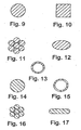
- the dimensions and shape of the flexible framework elements can vary from device to device or from framework element to framework element These dimensions include the length, thickness, or cross-sectional shape of the framework element ( e.g ., Figures 9-13 ). While the overall shape of the flexible framework elements follows a pattern having an alternating series of oppositely oriented apices, or vertices, along most or all of the length of the framework element ( Figures 3-7 ), the angle at which adjacent portions of the framework elements form the apexes, or vertices, is variable. Furthermore, the sections of framework element located between apices can be curved, straight, or other suitable shape ( e.g. , Figure 25 ).
- angles of the apices, or vertices are selected so an additional helically disposed flexible framework element can be placed next to a first flexible helically disposed framework element in such a way that apices of the first flexible framework element are adjacent apices of the additional flexible framework element ( e.g. , Figure 3 ).
- the apices, or vertices, of the flexible framework elements can have a variety of shapes.
- the shapes can be simple reverse-direction curves, angled turns in the pattern, or combinations thereof.
- eyelets and other shapes incorporating an open circular configuration can form an apex or vertex in the flexible framework elements of the present invention.
- Each flexible linkage element is threaded through the first and second flexible framework elements on a pathway, or course, separate and distinct from other flexible linkage elements along all or part of the length of the invention ( Figures 4 and 5 ).
- the flexible linkage elements can have a variety of cross-sectional shapes and areas ( e.g. , Figures 14-17 ).
- a length of a first flexible linkage element (16) is attached to a first flexible framework element (12).
- the first flexible linkage element is threaded over (or under) a portion of the first flexible framework element adjacent to, or forming part of, an apex in the first framework element ( Figure 4 ).
- the first flexible linkage element is then threaded under (or over, respectively) a nearby portion of a second flexible framework element adjacent to, or forming part of, an apex in the second flexible framework element ( Figure 4 ).
- the first flexible linkage element is threaded in this "over-and-under” process along all or part of the length of the invention to form a first course.
- a second flexible linkage element-(18) is similarly threaded from a second flexible framework element (14) through the first flexible framework along a second course separate and distinct from the first course ( Figure 5 ).
- the first flexible linkage element may need to be threaded through several "apex-forming portions" of the first flexible framework elements, as well.
- a similar arrangement for a second course is often employed.
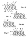
- first flexible framework elements and second flexible framework elements are both attached to a common flexible framework element (22) located at one or both ends of the invention ( Figures 18 - 21 and 25 - 27 ).
- first flexible framework element and the second flexible framework element each have terminal ends.
- the first and second flexible framework elements each have terminal ends that are individually attached to the common framework element.
- the common framework element is incorporated into, or otherwise continuous with, the flexible framework elements ( Figure 18 ).
- the common framework element eliminates some or all of the free ends of the flexible framework elements.
- Common framework elements can be made of any suitable non-bioabsorbable material and/or bioabsorbable material, including those materials listed herein.
- the cross-section, shape, configuration, and/or conformation of a common framework element can be similar to those of the flexible framework elements or they can be of another design. Inclusion of at least one common framework element with at least two flexible framework elements is readily accomplished by cutting an appropriate material according to a pattern.
- a first flexible framework element is attached directly to a second flexible framework element, without the use of a common framework element ( Figures 22 - 24 ).
- a first flexible linkage element (16) is attached to junction (30) of the first flexible framework element and the second flexible framework element
- the first flexible linkage element is then threaded through the most proximate apex-forming portion of the first flexible framework element (12).
- the first flexible linkage element is then threaded over, or under, the most proximate apex-forming portion of the second flexible framework element to begin a first course.
- the first flexible linkage element is alternately passed through the apices of the first flexible framework element and the second flexible framework element to form a first course.
- the first course is terminated by attaching the first flexible linkage element to junction (30a) of the first flexible framework element and the second flexible framework element.
- a second flexible linkage element (18) is attached to junction (32) of the second flexible framework element and the first flexible framework element.
- the second flexible linkage element is then threaded through the most proximate apex-forming portion of the second flexible framework element (14).
- the second flexible linkage element is then threaded over, or under, the most proximate apex-forming portion of the first flexible framework element to begin a second course.
- the second flexible linkage element is alternately passed through the apices of the second flexible framework element and the first flexible framework element to form a second course.
- the second course is terminated by attaching the second flexible linkage element to a junction of the second flexible framework element and the first flexible framework element.
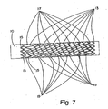
- first flexible linkage element and the second flexible linkage element tend to be located in the respective apices of the first flexible framework element and the second flexible framework element ( Figure 7 ).
- Connecting adjacent apices of separate flexible framework elements with flexible linkage elements following distinct courses imparts a high degree of mechanical flexibility, stability, and material variability to the invention. If desired, additional flexible framework elements and flexible linkage elements are included in the same fashion.
- the flexible elements of the present invention can be covered or coated with materials or substances that enhance biocompatibility, mechanical interaction of the elements, and/or resistance to thrombogenesis.
- the coating material or coating substance can also alter the absorption rate(s) of the bioabsorbable portion(s) of the invention.
- Materials suitable for covering the flexible elements are listed herein above. These materials can be applied In the form of extruded tubes, film wraps, powder coatings, and spray coatings. Suitable materials for coating flexible elements of the present invention included the compounds listed herein above.
- a preferred covering material (21) for constructing a stent-graft of the present invention ( Figure 8 ) is porous expanded polytetrafluoroethylene (ePTFE).
- Coverings and/or coatings placed on all or part of the flexible elements of the present invention can contain biologically active substances or entities.
- Preferred biologically active substances reduce or inhibit thrombus formation on the invention.
- Heparin, heparin analogs and derivatives are particularly preferred anti-thrombotic agents for use in the present invention.
- Other preferred biologically active substances reduce undesirable cellular growth in and around tissue in which the present invention is deployed and implanted.
- a preferred anti-proliferative agent for use in the present invention is dexamethasone.
- biologically active substances suitable for use in the present invention include enzymes, organic catalysts, ribozymes, organometallics, proteins, glycoproteins, peptides, polyamino acids, antibodies, nucleic acids, steroidal molecules, antibiotics, anti-inflammatories, antimycotics, cytokines, carbohydrates, oleophobics, lipids, extracellular matrix material and/or its individual components, pharmaceuticals, and therapeutics.
- Biological entities suitable for use in the present invention include mammalian cells, including genetically engineered cells, viruses, virenos, prions, and organelles, such as mitochondria.
- a delivery system as described in U.S. Patent Nos. 6, 827,731 and 6,899,727 are preferably used to deliver and deploy the present invention.
- This example describes the construction of a device of the present invention using a superelastic nitinol metal alloy.
- a length of superelastic (SE) nitinol wire having a diameter of 0.178mm (0.007inches) was obtained from Nitinol Devices and Components (Freemont, CA) and used to construct both framework elements.
- a first framework element was made by helically winding a first nitinol wire around a stainless steel "stent-jig" (10) having a central axis running the length of the jig.
- the jig also had a series of pins, approximately 0.5mm in diameter, projecting from the surface of the jig.
- the jig had a diameter of approximately 7mm.
- the pins were laid out so the finished helically disposed stent (12) had a pitch angle great enough to nest a second helically disposed stent therewithin ( Figure 1 ).
- the combined jig and helically disposed stent were subjected to a thermal cycle for 10 minutes in a convection oven (Carbolite, Watertown, WI) set at 450°C. Heating was followed by quenching the combination in distilled water at ambient temperature. Alternatively, the construction was subjected to a thermal cycle sufficient to set the austenite finish temperature to approximately 37°C.
- a second framework element was made by helically winding a second nitinol wire around a stainless steel "stent-jig" (10) having a central axis running the length of the jig.
- the jig also had a series of pins (not shown) projecting from the surface thereof.
- the pins had a diameter of approximately 6.7mm.
- the pins were laid out so the finished helically disposed stent (14) had a pitch angle sufficient to permit the second helical winding to nest within the first framework element.
- the combined jig and helically disposed stent were subjected to a thermal cycle for 10 minutes in a convection oven (Carbolite, Watertown, WI) set at 450°C. Heating was followed by quenching the combination in distilled water at ambient temperature.
- a convection oven Carbolite, Watertown, WI
- first framework element and the second framework element were both helically disposed around a stainless steel mandrel (10) having a common central axis.
- the diameter of the mandrel was approximately 7mm (0.275inch).
- the framework elements were rotated with respect to one another on the mandrel until apices from the first framework element (12) were aligned adjacent to apices from the second framework element (14).
- a first flexible linkage element (16) was formed from an ePTFE fiber (CV-5 Suture, W.L. Gore & Associates, Inc., Flagstaff, AZ) by tying the first-flexible linkage element to one terminus of the first framework element and weaving the first flexible linkage element between adjacent apices of the first framework element and the second framework element in a helical fashion to form a first course ( Figure 4 ). At the end of the first course, the first flexible linkage element was tied to the first framework element at the opposite terminus of the first framework element.
- ePTFE fiber CV-5 Suture, W.L. Gore & Associates, Inc., Flagstaff, AZ
- a second flexible linkage element (18) was formed from an ePTFE fiber (CV-5 Suture, W.L. Gore & Associates, Inc., Flagstaff, AZ) by tying the second flexible linkage element to one terminus of the second framework element and weaving the second flexible linkage element between adjacent apices of the first framework element and the second framework element in a helical fashion to form a second course distinct for the first course ( Figure 5 ).
- the first flexible linkage element has been deleted for clarity.
- the second flexible linkage element was tied to the second framework element at the opposite terminus of the second framework element. The finished device was then removed from the mandrel.
- FIG. 6 A side view of the completed device is illustrated in Figure 6 .
- This example describes the construction of an embodiment of the present invention having two framework elements made of a bioabsorbable material.
- the two flexible linkage elements were also made of a bioabsorbable material.
- a first framework element (13) was made of a polyglycolic acid - trimethylene carbonate (PGA:TMC) co-polymeric material.
- the PGA:TMC material was obtained in the form of an extruded monofilament from U.S. Surgical (Norwalk, CT) having a diameter of 0.38mm (0.015 inches). The monofilament had been stored under refrigeration.
- the polymeric mono-filament was wound onto a first stainless steel "stent-jig" made of a stainless steel mandrel (10) and having pins projecting outwardly from the surface of the mandrel.
- the pins had a diameter of approximately 6.7mm.
- the pins (not shown) were arranged in a pattern on the mandrel so the resulting first framework element had a pitch angle great enough to permit nesting of a second framework element within the first framework element ( Figure 7 ).
- the PGA:TMC mono-filamentous material was subjected to a heating and cooling cycle in a convection oven set at 150°C for ten minutes and allowed to cool to room temperature in air.
- the heating and cooling cycle set the first framework element in the shape of a helix disposed around a central axis that will be in common with a second framework element.
- the helical shape of the first framework element was retained after the framework element was removed from the stent-jig.
- Another polymeric PGA:TMC monofilament of similar dimensions was wound around a second stainless steel "stent-jig.”
- the second stent-jig was similar to the first stent-jig except for the placement of the pins on the mandrel portion of the jig.
- the pins were arranged in a pattern that complemented the pattern and pitch angle of the pins on the first stent-jig so the resulting second framework element (15) would wind around the same central axis as the first framework element so that apices of the first framework element and apices of the second framework element are located adjacent to one another.
- This second PGA:TMC mono-filamentous material was subjected to the same heating and cooling cycle as the first framework element.
- the resulting helically disposed second framework element was removed from the stent-jig and placed on a stainless steel mandrel (diameter 7mm) along with the first framework element.
- the two framework elements were rotated with respect to one another on the mandrel until the apices of the first framework element and apices of the second framework element were located adjacent to one another.
- the "nested" framework elements were connected with two separate flexible linkage elements ( Figure 7 ).
- the first flexible linkage element (17) was in the form of a fiber made of a polymeric bioabsorbable PGA:TMC material.
- the fiber obtained for this example was a Maxon Suture (Davis & Geck, Inc.).
- the first flexible linkage element was initially tied to one terminus of the first framework element and threaded over a portion of a linkage element forming an apex and under a portion of the linkage element forming the same apex.
- the first flexible linkage element was threaded through adjacent apices of the first framework element in the same manner until an apex of the second framework element was encountered.
- the first flexible linkage element was threaded from the first framework element over (or under) a portion of the second framework element forming the apex, through an space defined by the apex, and under (or over) the opposite portion of the second framework element forming the apex.
- the first flexible linkage element was threaded through adjacent apices of the "nested" first framework element and the second framework element in a helical fashion to form a first course ( Figure 7 ).
- the first course of the first flexible linkage continued past the opposite terminus of the second framework element through a series of adjacent apices of the first framework element.
- the first flexible linkage element was tied to the first framework element at the opposite terminus of the first framework element.
- a second flexible linkage element (19) was formed from a mono-filamentous bioabsorbable PGA:TMC Maxon Suture by tying the second flexible linkage element to one terminus of the second framework element and weaving the second flexible linkage over and under portions of the first framework element and the second framework element forming adjacent apices.
- the second flexible linkage element was threaded through the first framework element and the second framework element in a helical fashion to form a second course distinct for the first course ( Figure 7 ).
- the second flexible linkage element was tied to the second framework element at the opposite terminus of the second framework element. The finished device was then removed from the mandrel.
- FIG. 7 A side view of the completed device is illustrated in Figure 7 .
- This example describes construction of an embodiment of the present invention having a first framework element made of a metallic material and a second framework element made of a polymeric bioabsorbable material.
- the first flexible linkage element and the second flexible linkage element were made of a polymeric bioabsorbable material.
- a first framework element made of a superelastic (SE) nitinol wire was constructed as described in Example 1, supra .
- a second framework element made of a polymeric bioabsorbable material was constructed as described in Example 2, supra. The two finished framework elements were placed on a 7mm diameter mandrel and rotated with respect to one another on the mandrel until the apices of the first framework element and apices of the second framework element were located adjacent to one another.
- SE superelastic
- the “nested" framework elements were connected with a first flexible linkage element and a second flexible linkage element as described in Examples 1 and 2, supra.
- the flexible linkage elements were each made of a polymeric bioabsorbable PGA:TMC material in the form a Maxon Suture.
- This example describes covering at least one metallic framework element with a fluoropolymeric material prior to construction of a device of the present invention.
- a length of superelastic (SE) nitinol wire having a diameter of 0.178mm (0.007 inches) was obtained from Nitinol Devices and Components (Freemont, CA) and formed into a framework element as described in Example 1, supra.
- the formed wire was then attached to a machine having rotating chucks that permitted the formed wire to be carefully manipulated into a more straightened wire. This process was conducted in a refrigerated chamber to further manipulate the shape of the formed wire.
- the framework element retained its "shape-memory" throughout this process.
- a thin film of expanded porous polytetrafluoroethylene (W.L Gore & Associates, Inc., Flagstaff, AZ) was helically wrapped around the framework elements. After one pass of helical wrap around the extended metallic framework element, the chamber was warmed and the film-wrapped wire was allowed to reorder itself into the serpentine configuration. During this process, the film-wrapped flexible framework element was combined with another flexible framework element to form a tubular stent by rotating both framework elements in the same direction.
- This example describes covering at least one metallic framework element with a fluoropolymeric material prior to construction of a device of the present invention.
- a framework element was prepared and extended as described in Examples 1 and 4, respectively.
- an extruded tube of expanded porous polytetrafluoroethylene material having an inner diameter (I.D.) of 0.178 mm (0.007 inches) and an outer diameter (O.D.) of 0.254 mm (0.010 inches) was slid over the framework element.
- the covered framework element was then combined with another flexible framework element to construct a device of the present invention as described herein elsewhere.
- This example describes coating at least one framework element or flexible linkage element with a bioabsorbable material.
- a co-polymeric polyglycolic acid - trimethylene carbonate (PGA:TMC) material was dissolved in acetone and sprayed onto the flexible framework or flexible linkage element. Once the acetone solvent had evaporated, the element was used to construct a device of the present invention.
- PGA:TMC co-polymeric polyglycolic acid - trimethylene carbonate
- This example describes coating at least one framework element with a bioabsorbable material having at least one biologically active substance releasably incorporated therein.
- dexamethasone was added to the PGA:TMC solution described in Example 6 and sprayed onto a flexible element of the present invention.
- a device of the present invention was constructed using this coated element.
- a generally tubular stent construction having two helically would flexible framework elements was constructed as described herein, supra .
- the generally tubular flexible framework was inserted inside a generally tubular graft member (21) having an inner diameter sufficient to contact outer surfaces of at least one of the flexible framework elements.
- the tubular graft member was made of an expanded polytetrafluoroethylene material.
- a coupling member was used to attach the at least one flexible framework element to the graft member.
- the coupling member was in the form of a ribbon and covered only a portion of each flexible framework element. With this construction, regions of the flexible framework elements did not contact the coupling member.
- This example describes construction of an embodiment of the present invention in a tubular configuration having a common framework element incorporated at each end of the construction.
- the framework elements were metallic and the linkage elements were fluoropolymeric In composition.
- the metallic elements were formed by laser cutting a tubular piece of stainless steel according to a pattern. An uncut cylindrical piece of stainless steel was placed on a mandrel (10) for laser cutting.
- Figures 41 and 44 are representative examples of flexible framework elements of the present invention that can be formed with patterned laser cutting.
- Figures 18 - 21 are schematic representations showing one end of a tubular construction that had been cut open longitudinally and flattened. Although only one common end is shown in these figures, both ends of the tubular construction of this example had a common framework element.
- first flexible framework element (12) was attached to common framework element (22) at site (23) and one end of the second flexible framework element (14) was attached to common framework element at site (25).
- second flexible framework element (14) was attached to common framework element (22) at site (25).
- a common framework element was also placed at the opposite end of the construction in the same fashion.
- a first flexible linkage element (16) was attached to the construction at site (23) and threaded through an apex of the first flexible framework element (12) most proximate to the attachment site (23).
- the first flexible linkage element (16) was threaded through an apex of the common framework element adjacent the attachment site (23).
- the first flexible linkage element (16) was then threaded through the next available apex of the first framework element (12).
- the first flexible linkage element (16) was threaded through the apex of the second flexible framework element (14) most proximate to the previous apex of the first flexible framework element to form the beginning of a first course.
- the first flexible linkage element (16) was alternately threaded through apices of the first flexible framework element and the second flexible framework element as described elsewhere herein to complete the first course.
- the first course was terminated by attaching the first flexible linkage to a common framework element at the opposite end of the construction in a similar manner.
- a second flexible linkage element (18) was attached to the construction at site (25) and threaded through an apex of the second flexible framework element (14) most proximate to the attachment site (25).
- the second flexible linkage element (18) was threaded through an apex of the common framework element adjacent the attachment site (25).
- the second flexible linkage element (16) was then threaded through the next available apex of the second framework element (14).
- the second flexible linkage element (18) was threaded through the apex of the first flexible framework element (12) most proximate to the previous apex of the second flexible framework element to form the beginning of a second course.
- the second flexible linkage element (18) was alternately threaded through apices of the second flexible framework element and the first flexible framework element as described elsewhere herein to complete the second course.
- the second course was terminated by attaching the second flexible linkage to a common framework element at the opposite end of the construction in a similar manner.
- Figure 21 illustrates each of the elements of this embodiment in relation to one another.
- FIGS 25 - 27 illustrate tubular embodiments of the present invention having a common framework element (22) at both ends of the tubular construction.
- the framework elements (12, 14) in these embodiments are characterized by the absence of any sections that are straight. Every section of every framework element (12, 14, 22) was curved.
- Figure 25 illustrates a stent of the present invention placed on a mandrel (10).
- Figure 26 illustrates the stent of Figure 25 partially withdrawn from a mandrel and flexible linkage elements (16, 18) added.
- Figure 27 illustrates a stent-graft of the present invention having covering (21) placed over the flexible framework elements and flexible linkage elements illustrated in Figure 26 .
- This example describes construction of a stent-graft of the present invention.
- a tubular stent as described in Example 9, supra was obtained.
- a porous expanded polytetrafluoroethylene (ePTFE) material in a tubular form of was obtained from W.L. Gore & Associates, Inc., Flagstaff, AZ and slid over the outside of the stent as a covering (21).
- the covering was attached to the framework elements (12, 14) of the stent with a series of ribbon-like fluoropolymeric materials (not shown).
- the ribbon-like materials were wrapped around the stent-graft such that apices of the stent were trapped between the ribbon-like material and the covering.
- the ribbon-like material was attached to the covering though the localized application of heat.
- the tubular ePTFE material was placed inside the stent as a liner and the framework apices trapped between the liner and an externally applied fluoropolymeric ribbon-like material. The liner and ribbon-like material were attached through the localized application of heat.
- FIG. 22 This example describes construction of an embodiment of the present invention in which a first flexible framework element (12) was attached to a second flexible framework element (14) without the use of a common framework element ( Figures 22 - 24).
- Figure 22 has second flexible linkage element (18) omitted for clarity.
- Figure 23 has first flexible linkage element (16) omitted for clarity.
- the framework elements were metallic and the linkage elements were fluoropolymeric in composition.
- the metallic elements were formed by laser cutting a tubular piece of stainless steel according to a pattern. An uncut cylindrical piece of stainless steel was placed on a mandrel (10) for laser cutting.
- first flexible framework element (12) was attached to second framework element (14) at site (30).
- second flexible framework element (14) is shown attached to first flexible framework element (12) at site (32).
- the first flexible linkage element (16) was attached to the invention at site (30) and threaded through the apex of the first flexible framework element immediately adjacent to attachment site (30). The first flexible framework element was then threaded through the apex of the second flexible framework element immediately adjacent the aforementioned threaded apex of the first flexible framework element to form the beginnings of a first course. The first flexible linkage element was threaded through adjacent apices of the first flexible framework elements and the second flexible framework elements to form the first course. The first course was terminated by attaching the first flexible linkage element to site (30a) at the opposite end of the tubular construction.
- the second flexible linkage element (18) was attached to the invention at site (32) and threaded through the apex of the second flexible framework element immediately adjacent to attachment site (32).
- the second flexible framework element was then threaded through the apex of the first flexible framework element immediately adjacent the aforementioned threaded apex of the second flexible framework element to form the beginnings of a second course.
- the second flexible linkage element was threaded through adjacent apices of the second flexible framework elements and the first flexible framework elements to form the second course.
- the second course was terminated by attaching the second flexible linkage element to an attachment site at the opposite end of the tubular construction.
- This example describes construction of a stent-graft of the present invention ( Figure 24 ).
- a tubular stent as described in Example 11, supra was obtained.
- a porous expanded polytetrafluoroethylene (ePTFE) material in a tubular form of was obtained from W.L. Gore & Associates, Inc., Flagstaff, AZ and slid over the outside of the stent as a covering (21).
- the covering was attached to the framework elements (12, 14) of the stent with a series of ribbon-like fluoropolymeric materials (not shown).
- the ribbon-like materials were wrapped around the stent-graft such that apices of the stent were trapped between the ribbon-like material and the covering.
- the ribbon-like material was attached to the covering though the localized application of heat.
- the tubular ePTFE material was placed inside the stent as a liner and the framework apices trapped between the liner and an externally applied fluoropolymeric ribbon-like material. The liner and ribbon-like material were attached through the localized application of heat.
Landscapes
- Health & Medical Sciences (AREA)
- Engineering & Computer Science (AREA)
- Biomedical Technology (AREA)
- Cardiology (AREA)
- Oral & Maxillofacial Surgery (AREA)
- Transplantation (AREA)
- Heart & Thoracic Surgery (AREA)
- Vascular Medicine (AREA)
- Life Sciences & Earth Sciences (AREA)
- Animal Behavior & Ethology (AREA)
- General Health & Medical Sciences (AREA)
- Public Health (AREA)
- Veterinary Medicine (AREA)
- Prostheses (AREA)
Applications Claiming Priority (2)
| Application Number | Priority Date | Filing Date | Title |
|---|---|---|---|
| US11/378,048 US20070219618A1 (en) | 2006-03-17 | 2006-03-17 | Endoprosthesis having multiple helically wound flexible framework elements |
| PCT/US2007/006252 WO2007109007A1 (en) | 2006-03-17 | 2007-03-12 | Endoprosthesis having multiple helically wound flexible framework elements |
Publications (2)
| Publication Number | Publication Date |
|---|---|
| EP1996132A1 EP1996132A1 (en) | 2008-12-03 |
| EP1996132B1 true EP1996132B1 (en) | 2011-10-26 |
Family
ID=38179786
Family Applications (1)
| Application Number | Title | Priority Date | Filing Date |
|---|---|---|---|
| EP07752917A Not-in-force EP1996132B1 (en) | 2006-03-17 | 2007-03-12 | Endoprosthesis having multiple helically wound flexible framework elements |
Country Status (8)
| Country | Link |
|---|---|
| US (1) | US20070219618A1 (enExample) |
| EP (1) | EP1996132B1 (enExample) |
| JP (1) | JP5185249B2 (enExample) |
| AT (1) | ATE530151T1 (enExample) |
| AU (1) | AU2007227658B2 (enExample) |
| CA (1) | CA2645947C (enExample) |
| ES (1) | ES2373583T3 (enExample) |
| WO (1) | WO2007109007A1 (enExample) |
Families Citing this family (36)
| Publication number | Priority date | Publication date | Assignee | Title |
|---|---|---|---|---|
| US8382821B2 (en) | 1998-12-03 | 2013-02-26 | Medinol Ltd. | Helical hybrid stent |
| US20040267349A1 (en) | 2003-06-27 | 2004-12-30 | Kobi Richter | Amorphous metal alloy medical devices |
| US9039755B2 (en) * | 2003-06-27 | 2015-05-26 | Medinol Ltd. | Helical hybrid stent |
| US9155639B2 (en) * | 2009-04-22 | 2015-10-13 | Medinol Ltd. | Helical hybrid stent |
| US7637939B2 (en) * | 2005-06-30 | 2009-12-29 | Boston Scientific Scimed, Inc. | Hybrid stent |
| KR100633020B1 (ko) * | 2005-07-15 | 2006-10-11 | 주식회사 스텐다드싸이텍 | 스텐트 및 그의 제작 방법 |
| US20100070043A1 (en) * | 2005-08-04 | 2010-03-18 | Kitchen Michael S | Shape memory orthopedic joint |
| US8636791B1 (en) * | 2006-11-21 | 2014-01-28 | Seshadri Raju | Venous stent |
| US9539124B1 (en) | 2006-11-21 | 2017-01-10 | Seshadri Raju | Venous stent |
| WO2009041664A1 (ja) | 2007-09-27 | 2009-04-02 | Terumo Kabushiki Kaisha | ステントおよび生体器官拡張器具 |
| WO2009103789A1 (en) * | 2008-02-22 | 2009-08-27 | Hanssen Investment & Consultancy B.V. | Coiled assembly for supporting the wall of a lumen |
| WO2010111666A1 (en) | 2009-03-26 | 2010-09-30 | Taheri Laduca Llc | Vascular implants and methods |
| AU2016213923B9 (en) * | 2009-04-22 | 2017-11-16 | Medinol Ltd. | Helical hybrid stent |
| US20110071617A1 (en) * | 2009-09-18 | 2011-03-24 | Medtronic Vascular, Inc. | Stent With Improved Flexibility |
| WO2011056981A2 (en) | 2009-11-04 | 2011-05-12 | Nitinol Devices And Components, Inc. | Alternating circumferential bridge stent design and methods for use thereof |
| JP2011156094A (ja) * | 2010-01-29 | 2011-08-18 | Nipro Corp | ステント |
| US8206434B2 (en) * | 2010-03-02 | 2012-06-26 | Medtronic Vascular, Inc. | Stent with sinusoidal wave form and orthogonal end and method for making same |
| US9301864B2 (en) | 2010-06-08 | 2016-04-05 | Veniti, Inc. | Bi-directional stent delivery system |
| US8864811B2 (en) | 2010-06-08 | 2014-10-21 | Veniti, Inc. | Bi-directional stent delivery system |
| US9233014B2 (en) | 2010-09-24 | 2016-01-12 | Veniti, Inc. | Stent with support braces |
| WO2012047308A1 (en) | 2010-10-08 | 2012-04-12 | Nitinol Devices And Components, Inc. | Alternating circumferential bridge stent design and methods for use thereof |
| GB201021263D0 (en) | 2010-12-15 | 2011-01-26 | Ge Healthcare Ltd | Solid phase extraction method |
| AU2012203620B9 (en) * | 2011-06-24 | 2014-10-02 | Cook Medical Technologies Llc | Helical Stent |
| US8903506B2 (en) | 2011-08-12 | 2014-12-02 | Cardiac Pacemakers | Method for coating devices using electrospinning and melt blowing |
| US20130138219A1 (en) * | 2011-11-28 | 2013-05-30 | Cook Medical Technologies Llc | Biodegradable stents having one or more coverings |
| US8894701B2 (en) * | 2011-12-23 | 2014-11-25 | Cook Medical Technologies Llc | Hybrid balloon-expandable/self-expanding prosthesis for deployment in a body vessel and method of making |
| US9629735B2 (en) * | 2012-11-16 | 2017-04-25 | W. L. Gore & Associates, Inc. | Flexible endoluminal device |
| US20150025608A1 (en) | 2013-07-22 | 2015-01-22 | Cardiac Pacemakers, Inc. | Lubricious, biocompatible hydrophilic thermoset coating using interpenetrating hydrogel networks |
| US9403657B2 (en) | 2014-07-07 | 2016-08-02 | Precision, Inc. | Angular winding |
| US9855415B2 (en) | 2015-07-25 | 2018-01-02 | Cardiac Pacemakers, Inc. | Medical electrical lead with biostable PVDF-based materials |
| US10273114B2 (en) | 2016-07-01 | 2019-04-30 | Precision, Inc. | Multi-sided winding |
| US10465318B2 (en) | 2016-12-27 | 2019-11-05 | Boston Scientific Scimed Inc | Degradable scaffolding for electrospinning |
| US10441446B2 (en) * | 2017-08-31 | 2019-10-15 | Medtronic Vascular, Inc. | Endoluminal prostheses including multiple helical wires |
| JP7379766B2 (ja) * | 2018-02-28 | 2023-11-15 | Sbカワスミ株式会社 | ステント |
| US11291570B2 (en) | 2018-04-27 | 2022-04-05 | Cook Medical Technologies Llc | Hybrid stent and delivery system |
| US12478488B2 (en) | 2020-02-19 | 2025-11-25 | Medinol Ltd. | Helical stent with enhanced crimping |
Family Cites Families (105)
| Publication number | Priority date | Publication date | Assignee | Title |
|---|---|---|---|---|
| US3174851A (en) * | 1961-12-01 | 1965-03-23 | William J Buehler | Nickel-base alloys |
| AT261800B (de) * | 1966-08-22 | 1968-05-10 | Braun Internat Gmbh B | Verfahren zur Herstellung von röhrenförmigen, glatten bzw. mit einem Gewinde versehenen Gewebe-Blutgefäß-Prothesen |
| US3514791A (en) * | 1967-07-25 | 1970-06-02 | Charles H Sparks | Tissue grafts |
| US3657744A (en) * | 1970-05-08 | 1972-04-25 | Univ Minnesota | Method for fixing prosthetic implants in a living body |
| CA962021A (en) * | 1970-05-21 | 1975-02-04 | Robert W. Gore | Porous products and process therefor |
| US3753700A (en) * | 1970-07-02 | 1973-08-21 | Raychem Corp | Heat recoverable alloy |
| US3710777A (en) * | 1970-12-23 | 1973-01-16 | C Sparks | Method and apparatus for growing graft tubes in place |
| US3866609A (en) * | 1972-04-05 | 1975-02-18 | Charles Howard Sparks | Apparatus for growing graft tubes in place |
| US3866247A (en) * | 1972-04-05 | 1975-02-18 | Charles Howard Sparks | Graft tubes |
| US3868956A (en) * | 1972-06-05 | 1975-03-04 | Ralph J Alfidi | Vessel implantable appliance and method of implanting it |
| US3974526A (en) * | 1973-07-06 | 1976-08-17 | Dardik Irving I | Vascular prostheses and process for producing the same |
| US3949073A (en) * | 1974-11-18 | 1976-04-06 | The Board Of Trustees Of Leland Stanford Junior University | Process for augmenting connective mammalian tissue with in situ polymerizable native collagen solution |
| US4164045A (en) * | 1977-08-03 | 1979-08-14 | Carbomedics, Inc. | Artificial vascular and patch grafts |
| AU516741B2 (en) * | 1978-05-23 | 1981-06-18 | Bio Nova Neo Technics Pty. Ltd. | Vascular prostheses |
| WO1980000007A1 (en) * | 1978-06-02 | 1980-01-10 | A Rockey | Medical sleeve |
| US4425908A (en) * | 1981-10-22 | 1984-01-17 | Beth Israel Hospital | Blood clot filter |
| US4424208A (en) * | 1982-01-11 | 1984-01-03 | Collagen Corporation | Collagen implant material and method for augmenting soft tissue |
| US4582640A (en) * | 1982-03-08 | 1986-04-15 | Collagen Corporation | Injectable cross-linked collagen implant material |
| SE445884B (sv) * | 1982-04-30 | 1986-07-28 | Medinvent Sa | Anordning for implantation av en rorformig protes |
| US4494531A (en) * | 1982-12-06 | 1985-01-22 | Cook, Incorporated | Expandable blood clot filter |
| US4512338A (en) * | 1983-01-25 | 1985-04-23 | Balko Alexander B | Process for restoring patency to body vessels |
| US4503569A (en) * | 1983-03-03 | 1985-03-12 | Dotter Charles T | Transluminally placed expandable graft prosthesis |
| US4647416A (en) * | 1983-08-03 | 1987-03-03 | Shiley Incorporated | Method of preparing a vascular graft prosthesis |
| US4665906A (en) * | 1983-10-14 | 1987-05-19 | Raychem Corporation | Medical devices incorporating sim alloy elements |
| US4842575A (en) * | 1984-01-30 | 1989-06-27 | Meadox Medicals, Inc. | Method for forming impregnated synthetic vascular grafts |
| US4580568A (en) * | 1984-10-01 | 1986-04-08 | Cook, Incorporated | Percutaneous endovascular stent and method for insertion thereof |
| US4798606A (en) * | 1985-02-26 | 1989-01-17 | Corvita Corporation | Reinforcing structure for cardiovascular graft |
| US4642117A (en) * | 1985-03-22 | 1987-02-10 | Collagen Corporation | Mechanically sheared collagen implant material and method |
| US4738666A (en) * | 1985-06-11 | 1988-04-19 | Genus Catheter Technologies, Inc. | Variable diameter catheter |
| US5102417A (en) * | 1985-11-07 | 1992-04-07 | Expandable Grafts Partnership | Expandable intraluminal graft, and method and apparatus for implanting an expandable intraluminal graft |
| US4733665C2 (en) * | 1985-11-07 | 2002-01-29 | Expandable Grafts Partnership | Expandable intraluminal graft and method and apparatus for implanting an expandable intraluminal graft |
| US4665918A (en) * | 1986-01-06 | 1987-05-19 | Garza Gilbert A | Prosthesis system and method |
| US4649922A (en) * | 1986-01-23 | 1987-03-17 | Wiktor Donimik M | Catheter arrangement having a variable diameter tip and spring prosthesis |
| US4740207A (en) * | 1986-09-10 | 1988-04-26 | Kreamer Jeffry W | Intralumenal graft |
| US4800882A (en) * | 1987-03-13 | 1989-01-31 | Cook Incorporated | Endovascular stent and delivery system |
| US4816339A (en) * | 1987-04-28 | 1989-03-28 | Baxter International Inc. | Multi-layered poly(tetrafluoroethylene)/elastomer materials useful for in vivo implantation |
| US5133732A (en) * | 1987-10-19 | 1992-07-28 | Medtronic, Inc. | Intravascular stent |
| US4820298A (en) * | 1987-11-20 | 1989-04-11 | Leveen Eric G | Internal vascular prosthesis |
| US5192307A (en) * | 1987-12-08 | 1993-03-09 | Wall W Henry | Angioplasty stent |
| US4830003A (en) * | 1988-06-17 | 1989-05-16 | Wolff Rodney G | Compressive stent and delivery system |
| US5213580A (en) * | 1988-08-24 | 1993-05-25 | Endoluminal Therapeutics, Inc. | Biodegradable polymeric endoluminal sealing process |
| US5019090A (en) * | 1988-09-01 | 1991-05-28 | Corvita Corporation | Radially expandable endoprosthesis and the like |
| US5092877A (en) * | 1988-09-01 | 1992-03-03 | Corvita Corporation | Radially expandable endoprosthesis |
| SE8803444D0 (sv) * | 1988-09-28 | 1988-09-28 | Medinvent Sa | A device for transluminal implantation or extraction |
| CA1322628C (en) * | 1988-10-04 | 1993-10-05 | Richard A. Schatz | Expandable intraluminal graft |
| US5019085A (en) * | 1988-10-25 | 1991-05-28 | Cordis Corporation | Apparatus and method for placement of a stent within a subject vessel |
| US4913141A (en) * | 1988-10-25 | 1990-04-03 | Cordis Corporation | Apparatus and method for placement of a stent within a subject vessel |
| US5209735A (en) * | 1988-11-07 | 1993-05-11 | Lazarus Harrison M | External guide wire and enlargement means |
| US5100429A (en) * | 1989-04-28 | 1992-03-31 | C. R. Bard, Inc. | Endovascular stent and delivery system |
| US4990155A (en) * | 1989-05-19 | 1991-02-05 | Wilkoff Howard M | Surgical stent method and apparatus |
| US4994071A (en) * | 1989-05-22 | 1991-02-19 | Cordis Corporation | Bifurcating stent apparatus and method |
| US5015253A (en) * | 1989-06-15 | 1991-05-14 | Cordis Corporation | Non-woven endoprosthesis |
| DE9010130U1 (de) * | 1989-07-13 | 1990-09-13 | American Medical Systems, Inc., Minnetonka, Minn. | Instrument zum Anbringen eines Aufweitimplantats |
| CA2026604A1 (en) * | 1989-10-02 | 1991-04-03 | Rodney G. Wolff | Articulated stent |
| US5035706A (en) * | 1989-10-17 | 1991-07-30 | Cook Incorporated | Percutaneous stent and method for retrieval thereof |
| US5221261A (en) * | 1990-04-12 | 1993-06-22 | Schneider (Usa) Inc. | Radially expandable fixation member |
| US5123917A (en) * | 1990-04-27 | 1992-06-23 | Lee Peter Y | Expandable intraluminal vascular graft |
| US5122154A (en) * | 1990-08-15 | 1992-06-16 | Rhodes Valentine J | Endovascular bypass graft |
| ES2085435T3 (es) * | 1990-10-09 | 1996-06-01 | Cook Inc | Dispositivo dilatador percutaneo. |
| US5217483A (en) * | 1990-11-28 | 1993-06-08 | Numed, Inc. | Intravascular radially expandable stent |
| US5282847A (en) * | 1991-02-28 | 1994-02-01 | Medtronic, Inc. | Prosthetic vascular grafts with a pleated structure |
| US5290305A (en) * | 1991-10-11 | 1994-03-01 | Kanji Inoue | Appliance collapsible for insertion into human organs and capable of resilient restoration |
| CA2380683C (en) * | 1991-10-28 | 2006-08-08 | Advanced Cardiovascular Systems, Inc. | Expandable stents and method for making same |
| US5211658A (en) * | 1991-11-05 | 1993-05-18 | New England Deaconess Hospital Corporation | Method and device for performing endovascular repair of aneurysms |
| US5507767A (en) * | 1992-01-15 | 1996-04-16 | Cook Incorporated | Spiral stent |
| US5201757A (en) * | 1992-04-03 | 1993-04-13 | Schneider (Usa) Inc. | Medial region deployment of radially self-expanding stents |
| US5540712A (en) * | 1992-05-01 | 1996-07-30 | Nitinol Medical Technologies, Inc. | Stent and method and apparatus for forming and delivering the same |
| US5405378A (en) * | 1992-05-20 | 1995-04-11 | Strecker; Ernst P. | Device with a prosthesis implantable in the body of a patient |
| US5383928A (en) * | 1992-06-10 | 1995-01-24 | Emory University | Stent sheath for local drug delivery |
| US5324304A (en) * | 1992-06-18 | 1994-06-28 | William Cook Europe A/S | Introduction catheter set for a collapsible self-expandable implant |
| US5496365A (en) * | 1992-07-02 | 1996-03-05 | Sgro; Jean-Claude | Autoexpandable vascular endoprosthesis |
| US5306294A (en) * | 1992-08-05 | 1994-04-26 | Ultrasonic Sensing And Monitoring Systems, Inc. | Stent construction of rolled configuration |
| US5382261A (en) * | 1992-09-01 | 1995-01-17 | Expandable Grafts Partnership | Method and apparatus for occluding vessels |
| ES2089342T3 (es) * | 1992-10-31 | 1996-10-01 | Schneider Europ Ag | Disposicion de introduccion de una endoprotesis autoexpansible. |
| US5423849A (en) * | 1993-01-15 | 1995-06-13 | Target Therapeutics, Inc. | Vasoocclusion device containing radiopaque fibers |
| US5306261A (en) * | 1993-01-22 | 1994-04-26 | Misonix, Inc. | Catheter with collapsible wire guide |
| US5480423A (en) * | 1993-05-20 | 1996-01-02 | Boston Scientific Corporation | Prosthesis delivery |
| ATE252872T1 (de) * | 1994-04-01 | 2003-11-15 | Prograft Medical Inc | Selbstausdehnbarer stent bzw. stenttransplantat und verfahren zu ihrer vorbereitung |
| US6165210A (en) * | 1994-04-01 | 2000-12-26 | Gore Enterprise Holdings, Inc. | Self-expandable helical intravascular stent and stent-graft |
| US5540701A (en) * | 1994-05-20 | 1996-07-30 | Hugh Sharkey | Passive fixation anastomosis method and device |
| DE69528216T2 (de) * | 1994-06-17 | 2003-04-17 | Terumo K.K., Tokio/Tokyo | Verfahren zur Herstellung eines Dauerstents |
| US5522881A (en) * | 1994-06-28 | 1996-06-04 | Meadox Medicals, Inc. | Implantable tubular prosthesis having integral cuffs |
| US5509902A (en) * | 1994-07-25 | 1996-04-23 | Raulerson; J. Daniel | Subcutaneous catheter stabilizing devices and methods for securing a catheter using the same |
| US6015429A (en) * | 1994-09-08 | 2000-01-18 | Gore Enterprise Holdings, Inc. | Procedures for introducing stents and stent-grafts |
| US5591197A (en) * | 1995-03-14 | 1997-01-07 | Advanced Cardiovascular Systems, Inc. | Expandable stent forming projecting barbs and method for deploying |
| US5613981A (en) * | 1995-04-21 | 1997-03-25 | Medtronic, Inc. | Bidirectional dual sinusoidal helix stent |
| US5607442A (en) * | 1995-11-13 | 1997-03-04 | Isostent, Inc. | Stent with improved radiopacity and appearance characteristics |
| US6042605A (en) * | 1995-12-14 | 2000-03-28 | Gore Enterprose Holdings, Inc. | Kink resistant stent-graft |
| US6551350B1 (en) * | 1996-12-23 | 2003-04-22 | Gore Enterprise Holdings, Inc. | Kink resistant bifurcated prosthesis |
| FR2760351B1 (fr) * | 1997-03-04 | 1999-05-28 | Bernard Glatt | Dispositif formant endoprothese helicoidale et son procede de fabrication |
| US5911732A (en) * | 1997-03-10 | 1999-06-15 | Johnson & Johnson Interventional Systems, Co. | Articulated expandable intraluminal stent |
| EP1137373A4 (en) * | 1998-12-04 | 2004-05-19 | Chandrashekhar P Pathak | BIOCOMPATIBLE, CROSSLINKED POLYMERS |
| US6340366B2 (en) * | 1998-12-08 | 2002-01-22 | Bandula Wijay | Stent with nested or overlapping rings |
| EP1073385A2 (en) * | 1999-01-22 | 2001-02-07 | Gore Enterprise Holdings, Inc. | A biliary stent-graft |
| US6287333B1 (en) * | 1999-03-15 | 2001-09-11 | Angiodynamics, Inc. | Flexible stent |
| US6302907B1 (en) * | 1999-10-05 | 2001-10-16 | Scimed Life Systems, Inc. | Flexible endoluminal stent and process of manufacture |
| US6312458B1 (en) * | 2000-01-19 | 2001-11-06 | Scimed Life Systems, Inc. | Tubular structure/stent/stent securement member |
| US20020007215A1 (en) * | 2000-05-19 | 2002-01-17 | Robert Falotico | Drug/drug delivery systems for the prevention and treatment of vascular disease |
| US6648911B1 (en) * | 2000-11-20 | 2003-11-18 | Avantec Vascular Corporation | Method and device for the treatment of vulnerable tissue site |
| US20040249443A1 (en) * | 2001-08-20 | 2004-12-09 | Shanley John F. | Expandable medical device for treating cardiac arrhythmias |
| JP2003102849A (ja) * | 2001-09-28 | 2003-04-08 | Terumo Corp | 生体内留置用ステント |
| US6899729B1 (en) * | 2002-12-18 | 2005-05-31 | Advanced Cardiovascular Systems, Inc. | Stent for treating vulnerable plaque |
| US7458985B2 (en) * | 2003-01-27 | 2008-12-02 | Frank Madda | Spiral stent assembly |
| US20050131515A1 (en) * | 2003-12-16 | 2005-06-16 | Cully Edward H. | Removable stent-graft |
| US20050278017A1 (en) * | 2004-06-09 | 2005-12-15 | Scimed Life Systems, Inc. | Overlapped stents for scaffolding, flexibility and MRI compatibility |
-
2006
- 2006-03-17 US US11/378,048 patent/US20070219618A1/en not_active Abandoned
-
2007
- 2007-03-12 JP JP2009501452A patent/JP5185249B2/ja not_active Expired - Fee Related
- 2007-03-12 WO PCT/US2007/006252 patent/WO2007109007A1/en not_active Ceased
- 2007-03-12 ES ES07752917T patent/ES2373583T3/es active Active
- 2007-03-12 EP EP07752917A patent/EP1996132B1/en not_active Not-in-force
- 2007-03-12 CA CA2645947A patent/CA2645947C/en not_active Expired - Fee Related
- 2007-03-12 AT AT07752917T patent/ATE530151T1/de not_active IP Right Cessation
- 2007-03-12 AU AU2007227658A patent/AU2007227658B2/en not_active Ceased
Also Published As
| Publication number | Publication date |
|---|---|
| ATE530151T1 (de) | 2011-11-15 |
| CA2645947C (en) | 2011-05-24 |
| AU2007227658B2 (en) | 2011-07-21 |
| CA2645947A1 (en) | 2007-09-27 |
| AU2007227658A1 (en) | 2007-09-27 |
| US20070219618A1 (en) | 2007-09-20 |
| EP1996132A1 (en) | 2008-12-03 |
| WO2007109007A1 (en) | 2007-09-27 |
| JP2009530025A (ja) | 2009-08-27 |
| ES2373583T3 (es) | 2012-02-06 |
| JP5185249B2 (ja) | 2013-04-17 |
Similar Documents
| Publication | Publication Date | Title |
|---|---|---|
| EP1996132B1 (en) | Endoprosthesis having multiple helically wound flexible framework elements | |
| US6613077B2 (en) | Stent with controlled expansion | |
| CA1239755A (en) | Prosthesis comprising an expansible or contractile tubular body | |
| US5549663A (en) | Endoprosthesis having graft member and exposed welded end junctions, method and procedure | |
| AU729170B2 (en) | Three-dimensional braided covered stent | |
| US7534256B2 (en) | Intraluminal stent and graft | |
| US6517570B1 (en) | Exterior supported self-expanding stent-graft | |
| US8083790B2 (en) | ePTFE graft-stent composite device | |
| EP0866678B1 (en) | Kink-resistant stent graft | |
| AU783826B2 (en) | Spider silk covered stent | |
| CA2691064C (en) | Helical and segmented stent-graft | |
| US20080009934A1 (en) | Endoprosthesis delivery system with stent holder | |
| EP1029517A2 (en) | Staggered endoluminal stent | |
| JP2003520103A (ja) | 螺旋配置された固定部材を備えたステントグラフト | |
| US20020156523A1 (en) | Exterior supported self-expanding stent-graft | |
| WO2003092547A1 (en) | Hypotube endoluminal device | |
| JP2013059643A (ja) | 放射線不透過性ビーディングを有する移植片及びステント植皮 | |
| WO1997021403A9 (en) | Kink-resistant stent graft | |
| WO1996021404A1 (en) | Kink-resistant stent-graft | |
| US20050149081A1 (en) | Endovascular graft and graft trimmer | |
| CN110461382A (zh) | 腔内装置 | |
| WO2019111270A1 (en) | Braided scaffold and method of manufacturing thereof | |
| AU2002228982A1 (en) | Stent with controlled expansion |
Legal Events
| Date | Code | Title | Description |
|---|---|---|---|
| PUAI | Public reference made under article 153(3) epc to a published international application that has entered the european phase |
Free format text: ORIGINAL CODE: 0009012 |
|
| 17P | Request for examination filed |
Effective date: 20080919 |
|
| AK | Designated contracting states |
Kind code of ref document: A1 Designated state(s): AT BE BG CH CY CZ DE DK EE ES FI FR GB GR HU IE IS IT LI LT LU LV MC MT NL PL PT RO SE SI SK TR |
|
| GRAP | Despatch of communication of intention to grant a patent |
Free format text: ORIGINAL CODE: EPIDOSNIGR1 |
|
| GRAS | Grant fee paid |
Free format text: ORIGINAL CODE: EPIDOSNIGR3 |
|
| GRAA | (expected) grant |
Free format text: ORIGINAL CODE: 0009210 |
|
| DAX | Request for extension of the european patent (deleted) | ||
| AK | Designated contracting states |
Kind code of ref document: B1 Designated state(s): AT BE BG CH CY CZ DE DK EE ES FI FR GB GR HU IE IS IT LI LT LU LV MC MT NL PL PT RO SE SI SK TR |
|
| REG | Reference to a national code |
Ref country code: GB Ref legal event code: FG4D |
|
| REG | Reference to a national code |
Ref country code: CH Ref legal event code: EP |
|
| REG | Reference to a national code |
Ref country code: IE Ref legal event code: FG4D |
|
| REG | Reference to a national code |
Ref country code: DE Ref legal event code: R096 Ref document number: 602007018252 Country of ref document: DE Effective date: 20111222 |
|
| REG | Reference to a national code |
Ref country code: ES Ref legal event code: FG2A Ref document number: 2373583 Country of ref document: ES Kind code of ref document: T3 Effective date: 20120206 |
|
| REG | Reference to a national code |
Ref country code: NL Ref legal event code: VDEP Effective date: 20111026 |
|
| LTIE | Lt: invalidation of european patent or patent extension |
Effective date: 20111026 |
|
| REG | Reference to a national code |
Ref country code: AT Ref legal event code: MK05 Ref document number: 530151 Country of ref document: AT Kind code of ref document: T Effective date: 20111026 |
|
| PG25 | Lapsed in a contracting state [announced via postgrant information from national office to epo] |
Ref country code: LT Free format text: LAPSE BECAUSE OF FAILURE TO SUBMIT A TRANSLATION OF THE DESCRIPTION OR TO PAY THE FEE WITHIN THE PRESCRIBED TIME-LIMIT Effective date: 20111026 Ref country code: IS Free format text: LAPSE BECAUSE OF FAILURE TO SUBMIT A TRANSLATION OF THE DESCRIPTION OR TO PAY THE FEE WITHIN THE PRESCRIBED TIME-LIMIT Effective date: 20120226 Ref country code: BE Free format text: LAPSE BECAUSE OF FAILURE TO SUBMIT A TRANSLATION OF THE DESCRIPTION OR TO PAY THE FEE WITHIN THE PRESCRIBED TIME-LIMIT Effective date: 20111026 |
|
| PG25 | Lapsed in a contracting state [announced via postgrant information from national office to epo] |
Ref country code: SI Free format text: LAPSE BECAUSE OF FAILURE TO SUBMIT A TRANSLATION OF THE DESCRIPTION OR TO PAY THE FEE WITHIN THE PRESCRIBED TIME-LIMIT Effective date: 20111026 Ref country code: PL Free format text: LAPSE BECAUSE OF FAILURE TO SUBMIT A TRANSLATION OF THE DESCRIPTION OR TO PAY THE FEE WITHIN THE PRESCRIBED TIME-LIMIT Effective date: 20111026 Ref country code: NL Free format text: LAPSE BECAUSE OF FAILURE TO SUBMIT A TRANSLATION OF THE DESCRIPTION OR TO PAY THE FEE WITHIN THE PRESCRIBED TIME-LIMIT Effective date: 20111026 Ref country code: SE Free format text: LAPSE BECAUSE OF FAILURE TO SUBMIT A TRANSLATION OF THE DESCRIPTION OR TO PAY THE FEE WITHIN THE PRESCRIBED TIME-LIMIT Effective date: 20111026 Ref country code: LV Free format text: LAPSE BECAUSE OF FAILURE TO SUBMIT A TRANSLATION OF THE DESCRIPTION OR TO PAY THE FEE WITHIN THE PRESCRIBED TIME-LIMIT Effective date: 20111026 Ref country code: PT Free format text: LAPSE BECAUSE OF FAILURE TO SUBMIT A TRANSLATION OF THE DESCRIPTION OR TO PAY THE FEE WITHIN THE PRESCRIBED TIME-LIMIT Effective date: 20120227 Ref country code: GR Free format text: LAPSE BECAUSE OF FAILURE TO SUBMIT A TRANSLATION OF THE DESCRIPTION OR TO PAY THE FEE WITHIN THE PRESCRIBED TIME-LIMIT Effective date: 20120127 |
|
| PG25 | Lapsed in a contracting state [announced via postgrant information from national office to epo] |
Ref country code: CY Free format text: LAPSE BECAUSE OF FAILURE TO SUBMIT A TRANSLATION OF THE DESCRIPTION OR TO PAY THE FEE WITHIN THE PRESCRIBED TIME-LIMIT Effective date: 20111026 |
|
| PG25 | Lapsed in a contracting state [announced via postgrant information from national office to epo] |
Ref country code: DK Free format text: LAPSE BECAUSE OF FAILURE TO SUBMIT A TRANSLATION OF THE DESCRIPTION OR TO PAY THE FEE WITHIN THE PRESCRIBED TIME-LIMIT Effective date: 20111026 Ref country code: CZ Free format text: LAPSE BECAUSE OF FAILURE TO SUBMIT A TRANSLATION OF THE DESCRIPTION OR TO PAY THE FEE WITHIN THE PRESCRIBED TIME-LIMIT Effective date: 20111026 Ref country code: SK Free format text: LAPSE BECAUSE OF FAILURE TO SUBMIT A TRANSLATION OF THE DESCRIPTION OR TO PAY THE FEE WITHIN THE PRESCRIBED TIME-LIMIT Effective date: 20111026 Ref country code: BG Free format text: LAPSE BECAUSE OF FAILURE TO SUBMIT A TRANSLATION OF THE DESCRIPTION OR TO PAY THE FEE WITHIN THE PRESCRIBED TIME-LIMIT Effective date: 20120126 Ref country code: EE Free format text: LAPSE BECAUSE OF FAILURE TO SUBMIT A TRANSLATION OF THE DESCRIPTION OR TO PAY THE FEE WITHIN THE PRESCRIBED TIME-LIMIT Effective date: 20111026 |
|
| PG25 | Lapsed in a contracting state [announced via postgrant information from national office to epo] |
Ref country code: RO Free format text: LAPSE BECAUSE OF FAILURE TO SUBMIT A TRANSLATION OF THE DESCRIPTION OR TO PAY THE FEE WITHIN THE PRESCRIBED TIME-LIMIT Effective date: 20111026 |
|
| PLBE | No opposition filed within time limit |
Free format text: ORIGINAL CODE: 0009261 |
|
| STAA | Information on the status of an ep patent application or granted ep patent |
Free format text: STATUS: NO OPPOSITION FILED WITHIN TIME LIMIT |
|
| 26N | No opposition filed |
Effective date: 20120727 |
|
| PG25 | Lapsed in a contracting state [announced via postgrant information from national office to epo] |
Ref country code: MC Free format text: LAPSE BECAUSE OF NON-PAYMENT OF DUE FEES Effective date: 20120331 |
|
| REG | Reference to a national code |
Ref country code: CH Ref legal event code: PL |
|
| REG | Reference to a national code |
Ref country code: DE Ref legal event code: R097 Ref document number: 602007018252 Country of ref document: DE Effective date: 20120727 |
|
| PG25 | Lapsed in a contracting state [announced via postgrant information from national office to epo] |
Ref country code: CH Free format text: LAPSE BECAUSE OF NON-PAYMENT OF DUE FEES Effective date: 20120331 Ref country code: LI Free format text: LAPSE BECAUSE OF NON-PAYMENT OF DUE FEES Effective date: 20120331 Ref country code: AT Free format text: LAPSE BECAUSE OF FAILURE TO SUBMIT A TRANSLATION OF THE DESCRIPTION OR TO PAY THE FEE WITHIN THE PRESCRIBED TIME-LIMIT Effective date: 20111026 |
|
| PG25 | Lapsed in a contracting state [announced via postgrant information from national office to epo] |
Ref country code: FI Free format text: LAPSE BECAUSE OF FAILURE TO SUBMIT A TRANSLATION OF THE DESCRIPTION OR TO PAY THE FEE WITHIN THE PRESCRIBED TIME-LIMIT Effective date: 20111026 |
|
| PG25 | Lapsed in a contracting state [announced via postgrant information from national office to epo] |
Ref country code: MT Free format text: LAPSE BECAUSE OF FAILURE TO SUBMIT A TRANSLATION OF THE DESCRIPTION OR TO PAY THE FEE WITHIN THE PRESCRIBED TIME-LIMIT Effective date: 20111026 |
|
| PG25 | Lapsed in a contracting state [announced via postgrant information from national office to epo] |
Ref country code: TR Free format text: LAPSE BECAUSE OF FAILURE TO SUBMIT A TRANSLATION OF THE DESCRIPTION OR TO PAY THE FEE WITHIN THE PRESCRIBED TIME-LIMIT Effective date: 20111026 |
|
| PG25 | Lapsed in a contracting state [announced via postgrant information from national office to epo] |
Ref country code: LU Free format text: LAPSE BECAUSE OF NON-PAYMENT OF DUE FEES Effective date: 20120312 |
|
| PG25 | Lapsed in a contracting state [announced via postgrant information from national office to epo] |
Ref country code: HU Free format text: LAPSE BECAUSE OF FAILURE TO SUBMIT A TRANSLATION OF THE DESCRIPTION OR TO PAY THE FEE WITHIN THE PRESCRIBED TIME-LIMIT Effective date: 20070312 |
|
| REG | Reference to a national code |
Ref country code: GB Ref legal event code: 732E Free format text: REGISTERED BETWEEN 20150723 AND 20150729 |
|
| REG | Reference to a national code |
Ref country code: DE Ref legal event code: R082 Ref document number: 602007018252 Country of ref document: DE Representative=s name: MARKS & CLERK (LUXEMBOURG) LLP, LU Ref country code: DE Ref legal event code: R081 Ref document number: 602007018252 Country of ref document: DE Owner name: W.L. GORE & ASSOCIATES, INC., NEWARK, US Free format text: FORMER OWNER: GORE ENTERPRISE HOLDINGS, INC., NEWARK, DEL., US |
|
| REG | Reference to a national code |
Ref country code: FR Ref legal event code: PLFP Year of fee payment: 10 |
|
| REG | Reference to a national code |
Ref country code: FR Ref legal event code: TP Owner name: W.L. GORE & ASSOCIATES, INC., US Effective date: 20160510 |
|
| REG | Reference to a national code |
Ref country code: FR Ref legal event code: PLFP Year of fee payment: 11 |
|
| REG | Reference to a national code |
Ref country code: FR Ref legal event code: PLFP Year of fee payment: 12 |
|
| PGFP | Annual fee paid to national office [announced via postgrant information from national office to epo] |
Ref country code: IE Payment date: 20200227 Year of fee payment: 14 Ref country code: IT Payment date: 20200218 Year of fee payment: 14 Ref country code: GB Payment date: 20200221 Year of fee payment: 14 Ref country code: DE Payment date: 20200218 Year of fee payment: 14 |
|
| PGFP | Annual fee paid to national office [announced via postgrant information from national office to epo] |
Ref country code: FR Payment date: 20200220 Year of fee payment: 14 |
|
| PGFP | Annual fee paid to national office [announced via postgrant information from national office to epo] |
Ref country code: ES Payment date: 20200401 Year of fee payment: 14 |
|
| REG | Reference to a national code |
Ref country code: DE Ref legal event code: R119 Ref document number: 602007018252 Country of ref document: DE |
|
| GBPC | Gb: european patent ceased through non-payment of renewal fee |
Effective date: 20210312 |
|
| PG25 | Lapsed in a contracting state [announced via postgrant information from national office to epo] |
Ref country code: IE Free format text: LAPSE BECAUSE OF NON-PAYMENT OF DUE FEES Effective date: 20210312 Ref country code: FR Free format text: LAPSE BECAUSE OF NON-PAYMENT OF DUE FEES Effective date: 20210331 Ref country code: GB Free format text: LAPSE BECAUSE OF NON-PAYMENT OF DUE FEES Effective date: 20210312 Ref country code: DE Free format text: LAPSE BECAUSE OF NON-PAYMENT OF DUE FEES Effective date: 20211001 |
|
| PG25 | Lapsed in a contracting state [announced via postgrant information from national office to epo] |
Ref country code: IT Free format text: LAPSE BECAUSE OF NON-PAYMENT OF DUE FEES Effective date: 20210312 |
|
| REG | Reference to a national code |
Ref country code: ES Ref legal event code: FD2A Effective date: 20220523 |
|
| PG25 | Lapsed in a contracting state [announced via postgrant information from national office to epo] |
Ref country code: ES Free format text: LAPSE BECAUSE OF NON-PAYMENT OF DUE FEES Effective date: 20210313 |