EP1995353A1 - PROCEDE D'EXTRACTION / DE CONCENTRATION DE METAL FORMANT UN BROUILLARD METALLIQUE PRESENT DANS UN SEL FONDU, APPAREIL CORRESPONDANT, PROCEDE ET APPAREIL DE PRODUCTION DE Ti OU D'ALLIAGE DE Ti AU MOYEN DE CEUX-CI - Google Patents
PROCEDE D'EXTRACTION / DE CONCENTRATION DE METAL FORMANT UN BROUILLARD METALLIQUE PRESENT DANS UN SEL FONDU, APPAREIL CORRESPONDANT, PROCEDE ET APPAREIL DE PRODUCTION DE Ti OU D'ALLIAGE DE Ti AU MOYEN DE CEUX-CI Download PDFInfo
- Publication number
- EP1995353A1 EP1995353A1 EP07738118A EP07738118A EP1995353A1 EP 1995353 A1 EP1995353 A1 EP 1995353A1 EP 07738118 A EP07738118 A EP 07738118A EP 07738118 A EP07738118 A EP 07738118A EP 1995353 A1 EP1995353 A1 EP 1995353A1
- Authority
- EP
- European Patent Office
- Prior art keywords
- molten salt
- metal
- fog
- alloy
- molten
- Prior art date
- Legal status (The legal status is an assumption and is not a legal conclusion. Google has not performed a legal analysis and makes no representation as to the accuracy of the status listed.)
- Withdrawn
Links
Images


Classifications
-
- C—CHEMISTRY; METALLURGY
- C22—METALLURGY; FERROUS OR NON-FERROUS ALLOYS; TREATMENT OF ALLOYS OR NON-FERROUS METALS
- C22B—PRODUCTION AND REFINING OF METALS; PRETREATMENT OF RAW MATERIALS
- C22B34/00—Obtaining refractory metals
- C22B34/10—Obtaining titanium, zirconium or hafnium
- C22B34/12—Obtaining titanium or titanium compounds from ores or scrap by metallurgical processing; preparation of titanium compounds from other titanium compounds see C01G23/00 - C01G23/08
- C22B34/129—Obtaining titanium or titanium compounds from ores or scrap by metallurgical processing; preparation of titanium compounds from other titanium compounds see C01G23/00 - C01G23/08 obtaining metallic titanium from titanium compounds by dissociation, e.g. thermic dissociation of titanium tetraiodide, or by electrolysis or with the use of an electric arc
-
- C—CHEMISTRY; METALLURGY
- C22—METALLURGY; FERROUS OR NON-FERROUS ALLOYS; TREATMENT OF ALLOYS OR NON-FERROUS METALS
- C22B—PRODUCTION AND REFINING OF METALS; PRETREATMENT OF RAW MATERIALS
- C22B34/00—Obtaining refractory metals
- C22B34/10—Obtaining titanium, zirconium or hafnium
- C22B34/12—Obtaining titanium or titanium compounds from ores or scrap by metallurgical processing; preparation of titanium compounds from other titanium compounds see C01G23/00 - C01G23/08
- C22B34/1263—Obtaining titanium or titanium compounds from ores or scrap by metallurgical processing; preparation of titanium compounds from other titanium compounds see C01G23/00 - C01G23/08 obtaining metallic titanium from titanium compounds, e.g. by reduction
- C22B34/1268—Obtaining titanium or titanium compounds from ores or scrap by metallurgical processing; preparation of titanium compounds from other titanium compounds see C01G23/00 - C01G23/08 obtaining metallic titanium from titanium compounds, e.g. by reduction using alkali or alkaline-earth metals or amalgams
- C22B34/1272—Obtaining titanium or titanium compounds from ores or scrap by metallurgical processing; preparation of titanium compounds from other titanium compounds see C01G23/00 - C01G23/08 obtaining metallic titanium from titanium compounds, e.g. by reduction using alkali or alkaline-earth metals or amalgams reduction of titanium halides, e.g. Kroll process
-
- C—CHEMISTRY; METALLURGY
- C25—ELECTROLYTIC OR ELECTROPHORETIC PROCESSES; APPARATUS THEREFOR
- C25C—PROCESSES FOR THE ELECTROLYTIC PRODUCTION, RECOVERY OR REFINING OF METALS; APPARATUS THEREFOR
- C25C3/00—Electrolytic production, recovery or refining of metals by electrolysis of melts
- C25C3/02—Electrolytic production, recovery or refining of metals by electrolysis of melts of alkali or alkaline earth metals
-
- C—CHEMISTRY; METALLURGY
- C25—ELECTROLYTIC OR ELECTROPHORETIC PROCESSES; APPARATUS THEREFOR
- C25C—PROCESSES FOR THE ELECTROLYTIC PRODUCTION, RECOVERY OR REFINING OF METALS; APPARATUS THEREFOR
- C25C3/00—Electrolytic production, recovery or refining of metals by electrolysis of melts
- C25C3/26—Electrolytic production, recovery or refining of metals by electrolysis of melts of titanium, zirconium, hafnium, tantalum or vanadium
- C25C3/28—Electrolytic production, recovery or refining of metals by electrolysis of melts of titanium, zirconium, hafnium, tantalum or vanadium of titanium
-
- C—CHEMISTRY; METALLURGY
- C22—METALLURGY; FERROUS OR NON-FERROUS ALLOYS; TREATMENT OF ALLOYS OR NON-FERROUS METALS
- C22B—PRODUCTION AND REFINING OF METALS; PRETREATMENT OF RAW MATERIALS
- C22B26/00—Obtaining alkali, alkaline earth metals or magnesium
- C22B26/20—Obtaining alkaline earth metals or magnesium
Definitions
- the present invention relates to a method of removing/concentrating a metal-fog-forming metal, for example Ca or Na, dissolved in a molten salt containing such a metal-fog-forming metal as a constituent thereof, the method comprising removing the metal-fog-forming metal from the molten salt and transferring the same to other metal-fog-forming metal containing molten salt to increase the concentration thereof, and to an apparatus therefor, as well as to a process for producing Ti or a Ti alloy by use of the above method in carrying out the reduction treatment of a TiCl 4 -based metal chloride mixture with Ca to produce Ti or a Ti alloy, and to an apparatus therefor.
- a metal-fog-forming metal for example Ca or Na
- Such metals as Ti, Zr, Ta, Hf and V are useful metals respectively having desirable characteristics but can be hardly refined using such a conventional reducing agent as C or Al. It is necessary to separate those metals from co-existent congeners and from impurities and, therefore, they are generally produced by refining through a number of steps such as solvent extraction, roasting and chlorination, followed by conversion to oxides or chlorides, further followed by reduction thereof with a strong reducing agent such as Mg, Al, Na or Ca.
- Reducing agents such as Ca, Na and Al and, further, Li, by nature, are themselves soluble in metal chlorides (e.g. Ca is soluble in CaCl 2 ) and, on the occasion of dissolution, they produce a foggy matter called "metal fog".
- metals are referred to herein as "metal-fog-forming metals”.
- metal-fog-forming metals are refined from raw material ores through various refining treatments to give their respective pure forms for use in various fields of application, including the use of such reducing agents as mentioned above.
- the chlorides and fluorides, among others, of these metals are often used also in the form of molten salts either alone or in multi-component systems containing another salt or other salts and, in particular, they are widely used as industrial electrolytic baths in molten salt electrolysis.
- metallic titanium is produced via a reduction step and a vacuum separation step.
- the reduction step TiCl 4 in liquid form, fed to a reaction vessel from above, is reduced by molten Mg to form particles of metallic Ti, which successively move downward to give spongy metallic Ti.
- the vacuum separation step the unreacted portion of Mg and the by-product MgCl 2 are removed from the spongy metallic Ti occurring in the reaction vessel.
- the Ti powder formed moves downward in an aggregated state due to wettability (viscosity) of the molten Mg and, during moving downward, grains thereof are sintered and grown due to the heat which the high-temperature melt harbors, making it difficult to recover them out of the reaction vessel. Therefore, the metallic Ti production cannot be performed in a continuous manner; hence productivity is impaired.
- United States Patent No. 2, 205, 854 describes that Ca, for example, can be used instead of Mg as an agent for reducing TiCl 4 .
- United States Patent No. 4,820,339 describes a process for producing Ti by utilizing reduction reaction with Ca which comprises maintaining a CaCl 2 -based molten salt in a reaction vessel, feeding a metallic Ca powder to the molten salt from above to allow the Ca to be dissolved in the molten salt while feeding TiCl 4 gas from below to thereby cause the molten Ca to react with the TiCl 4 in the CaCl 2 -based molten salt.
- the process described in the above-cited Japanese Patent Application Publication No. 2005-133195 comprises introducing a Ca-rich molten CaCl 2 supplemented with Ca formed by electrolysis into a reaction vessel for use in formation of Ti particles by reduction with Ca, and the process described in Japanese Patent Application Publication No. 2005-133196 further comprises using an alloy electrode (e.g. Mg-Ca alloy electrode) as the cathode for effectively suppressing the back reaction in association with the electrolysis.
- an alloy electrode e.g. Mg-Ca alloy electrode
- the present inventors attempted to develop a metallic Ti or Ti alloy production process whose basic constitution is based on the OYIK process and which can be carried out efficiently and stably on a commercial scale and made investigations on all the production steps in that process.
- CaCl 2 containing a metal-fog-forming metal such as Ca or Na as a constituent thereof, with the metal-fog-forming metal (Ca) dissolved therein, and, at the same time, the thus-removed metal-fog-forming metal can be transferred to another molten salt composition (molten salt composition containing the metal-fog-forming metal as a constituent thereof), as well as an apparatus for use in carrying out such method.
- the present invention has been made to accomplish the obj ects mentioned above and is now described in its three aspects, namely" 1. method of removing/concentrating a metal-fog-forming metal in a molten salt, and apparatus therefor", "2.process for producing Ti or a Ti alloy which includes a Ca recovery step, and apparatus therefor” and "3.process for producing Ti or a Ti alloy which includes a Ca removing/concentrating step, and apparatus therefor".
- the present inventors made investigations concerning the case that the metal-fog-forming metal is Ca. As a result, it was found that when the molten salt (CaCl 2 ) is held in a treatment vessel (hereinafter, referred to as "vessel A") and a Ca-containingmoltenalloy(amoltenMg-Caalloy) isheldthereon in contact with the molten salt and a voltage below the decomposition voltage for CaCl 2 is applied so that the electrode plate on the molten alloy side may serve as a negative (-) electrode and the electrode plate on the molten salt side as a positive (+) electrode, the Ca dissolved in the molten salt can be rapidly absorbed into the molten alloy, thus being removed.
- a treatment vessel hereinafter, referred to as "vessel A”
- a Ca-containingmoltenalloy(amoltenMg-Caalloy) isheldthereon in contact with the molten salt and a voltage below the decomposition voltage for Ca
- the Ca is transferred from the molten alloy side to the molten salt side.
- metal-fog-forming metal so referred to herein is a metal strong in reducing power, soluble itself in corresponding metal chloride (e.g. Ca being soluble in CaCl 2 ) and capable of forming a fog called a metal fog on the occasion of dissolution, such as Ca, Li, Na or Al.
- a metal-fog-forming-metal containing molten salt refers to the molten salt in which a metal-fog-forming metal is contained as a constituent thereof, for example a molten CaCl 2 or a molten NaCl.
- a molten salt mixture consisted of one or more of metal-fog-forming metal containing molten salts should mean, in the case of the metal-fog-forming metal being Ca, for instance, either a molten CaCl 2 alone or a molten salt mixture comprising a molten CaCl 2 and CaF 2 or the like that is added for lowering the melting point and adjusting the viscosity, for instance.
- a metal-fog-forming metal containing molten alloy is an alloy in a molten state with the metal-fog-forming metal being contained therein as a constituent thereof and, in the case of the metal-fog-forming metal being Ca, for instance, it indicates a molten Mg-Ca alloy, a molten Pb-Ca alloy or the like.
- the electrodes between which a voltage is to be applied are designated as "negative (-) electrode” and “positive (+) electrode”, as so referred to hereinabove, for avoiding the confusion thereof with the terms “anode” and “cathode”, which are used on the premise that a salt bath (herein, molten salt) is electrolyzed.
- a salt bath herein, molten salt
- the method ofremoving/concentrating a metal-fog-forming metal according to the present invention as described above under (1) can be carried out in a mode of embodiment in which the metal-fog-forming metal is Ca and the metal-fog-forming metal containing molten salt is a Ca-containing molten salt and, further, in a desirable mode of embodiment in which the metal-fog-forming metal is Ca and the metal-fog-forming metal containing molten salt is CaCl 2 .
- the "Ca-containing molten salt" just mentioned above refers to CaCl 2 or CaF 2 , for instance.
- the applied voltage is lower than 3.2 V, it is possible to cause Ca to be dissolved in molten alloy without causing decomposition of CaCl 2 while controlling the voltage to be applied at specific numerical value levels.
- metal-fog-forming metal removing/concentrating apparatus in the metal-fog-forming metal removing/concentrating apparatus according to the present invention as described above under (2), a mode of embodiment is possible in which the metal-fog-forming metal is Ca and the metal-fog-forming-metal containing molten salt is a Ca-containing molten salt and, further, a mode of embodiment is possible in which the metal-fog-forming metal is Ca and the metal-fog-forming metal containing molten salt is CaCl 2 , in the apparatus as described above under (2).
- the method of removing/concentrating a metal-fog-forming metal in a molten salt according to the present invention makes it possible to remove the metal-fog-forming metal, for example Ca or Na, that is dissolved in one portion of a molten salt mixture consisted of one or more of metal-fog-forming metal containing molten salts therefrom and transfer the same to the othe portion of molten salt mixture to increase the concentration of the metal-fog-forming metal therein, both portions of molten salt mixture being respectively in contact with a metal-fog-forming metal containing alloy.
- This method can be carried out easily and properly using the apparatus according to the present invention.
- a so-called back reaction namely the reaction of the Ca in the molten salt with the chlorine formed by electrolysis, may occur and lower the current efficiency; the higher the Ca concentration in the molten salt is, the more significant the decrease in current efficiency is.
- the temperature uniformity in the molten salt (salt bath) within the electrolytic cell will be disturbed by the heat of reaction as resulting from the back reaction, possibly causing troubles in salt bath temperature control.
- the present inventors made various investigations in an attempt to inhibit the Ca concentration in the molten salt to be fed to the reaction vessel from fluctuating, to maintain that concentration at high levels, and further to suppress the back reaction by rapidly recovering Ca, namely removing Ca, in the molten salt to be fed to the electrolytic cell.
- the present inventors made detailed investigations concerning the configuration of an electrolytic cell vessel of a main electrolytic cell, the configuration of electrodes, electrolysis conditions, and a distance between the electrodes, among others, and, as a result, found that when the molten salt is electrolyzed while causing the same to flow in one direction in the vicinity of the cathode surface and the molten salt enhanced in Ca concentration is recovered on the outlet side of the electrolytic cell, it is possible to suppress the back reaction and maintain the current efficiency at a high level and, at the same time, effectively take out the Ca-enriched molten salt alone and, further, continuously treat the CaCl 2 -containing molten salt in large quantity and increase the feeding rate of Ca to the reaction vessel.
- the Ti or Ti alloy production process including the Ca recovery step according to the present invention and the apparatus therefor have been developed based on the above findings and have constitutions/features as shown in (3) and (4), respectively.
- a process for producing Ti or a Ti alloy comprising: a reduction step in which a CaCl 2 -containing molten salt with Ca dissolved therein is held in a reaction vessel and the Ca in the molten salt is allowed to react with a TiCl 4 -based metal chloride to form Ti particles or Ti alloy particles in said molten salt; a separation step in which said Ti particles or Ti alloy particles are separated from the molten salt within said reaction vessel or outside the reaction vessel; an electrolysis step in which the molten salt taken out of said reaction vessel is electrolyzed to form Ca to thereby increase the Ca concentration in the molten salt; a return step in which the Ca formed by said electrolysis is introduced, either alone or together with the molten salt, into said reaction vessel; and a Ca recovery step in which while the molten salt separated in said separation step and to be sent to said electrolysis step is kept in contact with a Ca- and Mg-containing molten alloy, a voltage below the decomposition voltage for CaCl 2 is applied so that
- the "CaCl 2 -containing molten salt” so referred to herein is either molten CaCl 2 alone or a molten salt mixture consisted of a molten CaCl 2 and CaF 2 etc to be added for lowering a melting point and adjusting viscosity thereof, among others. It is sometimes referred to as a "molten salt” or a “molten CaCl 2 " for short.
- TiCl 4 -based metal chloride refers to TiCl 2 alone or a mixture of TiCl 4 and other metal chlorides, the metals as constituent being intended for alloy elements in a Ti alloy, for example V, Al and/or Cr. Since the other metal chlorides are also reduced by Ca simultaneously with the reduction of TiCl 4 , a Ti alloy can be produced by using such a TiCl 4 -based mixed metal chloride as raw material.
- the applied voltage is lower than 3.2 V, it is possible to control its applied voltage at specific numerical value levels and thereby cause the Ca dissolved in CaCl 2 to be rapidly absorbed into the molten alloy without allowing the decomposition of CaCl 2 .
- the molten salt increased in Ca concentration in an electrolysis step is introduced into a regulating vessel provided with a Ca supply source and the molten salt is thus brought into contact with the Ca supply source and thereby rendered constant in Ca concentration and thereafter sent to the reduction step, it becomes possible to maintain the Ca concentration in the molten salt introduced into the reaction vessel always at a constant high level to thereby allow the reduction reaction to proceed efficiently.
- the molten alloy increased in Ca concentration as a result of absorption of Ca in the Ca recovery step is used as the Ca supply source or part of it for the regulating vessel, it becomes possible to effectively utilize the portion of Ca that has been removed for suppressing the back reaction, which is desirable.
- An apparatus for producing Ti or a Ti alloy comprising: a reaction vessel for holding a CaCl 2 -containing molten salt with Ca being dissolved therein and reacting a metal chloride containing TiCl 4 , the TiCl 4 being to be fed into said molten salt, with the Ca to cause the formation of Ti particles or Ti alloy particles therein; separation means for separating the Ti particles or Ti alloy particles formed in said molten salt therefrom; an electrolytic cell which holds a left molten salt after separation of said Ti particles or Ti alloy particles and is equipped with an anode and a cathode for carrying out electrolysis in the left molten salt to form Ca on the cathode side; return means for introducing the Ca formed by said electrolysis, either alone or together with an electrolyte molten salt, into the reaction vessel; and Ca recovery means for applying, while keeping the left molten salt separated by the separation means and to be fed to the electrolytic cell in contact with a Ca- and Mg-containing molten alloy, a
- the Ti or Ti alloy production apparatus described above under (4) further comprises a regulating vessel provided with a Ca supply source and intended for introducing molten salt in an electrolytic cell thereinto and bringing the same into contact with the Ca supply source to thereby render the Ca concentration in the molten salt constant and, thereafter, feeding that molten salt into the reaction vessel, the apparatus can be suitably used for carrying out the production process described above under (3).
- the Ti or Ti alloy production process comprising the Ca recovery step of the present invention, it is possible to rapidly recover the Ca dissolved in molten salt and thus suppress back reaction on the occasion of electrolysis of the molten salt to thereby enhance the efficiency of Ca formation. Furthermore, the process can contribute not only to increase the Ca concentration in the molten salt to be sent to the reduction step, simultaneously with the Ca recovery, and to enhance the efficiency of Ca formation, but also to enhance the efficiency of the TiCl 4 reduction reaction.
- the process makes it possible to inhibit the fluctuation of and to maintain at a high level the Ca concentration in the molten salt to be fed to the reaction vessel by using the regulating vessel provided with a Ca supply source and thus carry out the TiCl 4 reduction reaction efficiently and, further, continuously treat the CaCl 2 -containing molten salt in large quantity in the electrolysis step and thereby increase the feeding rate of Ca to the reaction vessel.
- the present inventors made various investigations to inhibit the fluctuation of and maintain at a high level the Ca concentration in the molten salt to be fed into the reaction vessel, at the same time, to rapidly recover and remove the Ca in the molten salt to be fed to the electrolytic cell therefrom to thereby suppress the back reaction so that the operation can be carried out in an efficient and stable manner on a commercial scale.
- the molten alloy increased in Ca concentration as a result of Ca absorption caused by voltage application to the molten salt can be used as the Ca supply source for the regulating vessel.
- the present inventors found that by electrolyzing the molten salt while causing the same to flow in one direction in the vicinity of the cathode surface and by recovering the molten salt increased in Ca concentration on the outlet side of the electrolytic cell, it becomes possible to suppress the back reaction and maintain the current efficiency at a high level and, at the same time, it becomes possible to effectively take out the Ca-enriched molten salt alone and, further, continuously treat the CaCl 2 -containing molten salt in large quantity and thereby increase the feeding rate of Ca to the reaction vessel.
- the Ti or Ti alloy production process comprising the Ca removing/concentrating step according to the present invention and the apparatus therefor have been developed based on such findings and have constitutions/features shown in (5) and (6) below.
- CaCl 2 -containing molten salt and "TiCl 4 -based metal chloride” are as exactly as defined in the above “2: Ti or Ti alloy production process comprising a Ca recovery step”.
- the applied voltage is lower than 3.2 V, it is possible to control the applied voltage at a specific numerical value level and cause rapid absorption of the Ca dissolved in CaCl 2 into the molten alloy without allowing decomposition of CaCl 2 .
- the molten salt increased in Ca concentration in the electrolysis step is introduced into the regulating vessel provided with a Ca supply source and brought into contact with the Ca supply source to render the Ca concentration in the molten salt constant and, thereafter, the resulting molten salt is sent to the reduction step, it enables the Ca concentration in the molten salt to be introduced into the reaction vessel to be maintained always at a constant high level, thus allowing the reduction reaction to proceed efficiently.
- the Ti or Ti alloy production apparatus described above under (6) further comprises a regulating vessel provided with a Ca supply source and intended for introducing molten salt in the electrolytic cell thereinto and bringing the same into contact with the Ca supply source to thereby render the Ca concentration in the molten salt constant and, thereafter, feeding that molten salt into the reaction vessel
- the apparatus can be suitably used for carrying out the production process described above under (5).
- the Ti or Ti alloy production process comprising a Ca removing/concentrating step according to the present invention, it is possible to rapidly remove the Ca dissolved in the molten salt therefrom and thus suppress the back reaction on the occasion of electrolysis of the molten salt to thereby enhance the efficiency of Ca formation. Furthermore, the process can contribute not only to increase the Ca concentration in the molten salt to be sent to the reduction step, simultaneously with the Ca removal, and enhance the efficiency of Ca formation but also to enhance the efficiency of the TiCl 4 reduction reaction.
- the process makes it possible to inhibit the fluctuation of and maintain at a high level the Ca concentration in the molten salt to be fed to the reaction vessel by using the regulating vessel provided with a Ca supply source and thus carry out the TiCl 4 reduction reaction efficiently and, further, continuously treat the CaCl 2 -containing molten salt in large quantity in the electrolysis step to thereby increase the feeding rate of Ca to the reaction vessel.
- Fig. 1 is a schematic representation of an example of the principal constitution/feature of an apparatus to be used in carrying out the method of removing/concentrating a metal-fog-forming metal in molten salt according to the present invention.
- the constitution/feature shown is the same as that of a Ca removing/concentrating unit 28 in Fig. 6 or Fig. 7 , which is to be hereinafter referred to and in which the same reference numerals are used. Further, in Fig.
- Ca denotes a metal-fog-forming metal
- a molten CaCl 2 denotes a molten salt mixture consisted of one or more of metal-fog-forming metal containing molten salts
- a molten Mg-Ca alloy denotes a metal-fog-forming metal containing molten alloy
- this apparatus has a Ca removing/concentration vessel 28a, and a molten CaCl 2 is held in this vessel 28a in a condition separated into a Ca-concentrating region 29 and a Ca-removing region 30 by a partition wall 31, and a molten Mg-Ca alloy 8 is held thereon in contact with each portion of the molten salt held in the Ca-concentrating region 29 and Ca-removing region 30.
- an electrode plate 33 for applying a voltage below a decomposition voltage for CaCl 2 so that the molten salt side in the Ca-removing region 30 may be on the positive (+) electrode side against the molten salt side in the Ca-concentrating region 29.
- an electrode plate 34 is disposed so that the electrode plate on the molten salt side in the Ca-concentrating region 29 may serve as a negative (-) electrode, as shown in the figure.
- the Ca-concentrating region 29 and Ca-removing region 30 are separated from each other by the partition wall 31 but the invention is not limited to this constitution/feature.
- a constitution/feature such that both regions are apart from each other by the use of two independent, detachable cells may also be employed.
- a molten CaCl 2 as molten salt with Ca dissolved therein is first held in the Ca-concentrating region 29 in the Ca removing/concentrating vessel 28a as well as in the Ca-removing region 30 separated from the concentrating region 29 by the partition wall 31. Further, a molten Mg-Ca alloy 8 is held onto the molten salt in both regions 29 and 30 in contact with both portions of the molten salt.
- the electrode plate 33 on the molten salt side in the Ca-removing region 30 may serve as a positive (+) electrode against the electrode plate 34 on the molten salt side in the Ca-concentrating region 29.
- the molten Mg-Ca alloy 8 existing in the adjacent surface of contact with the molten salt in the Ca-removing region 30 functions as a negative (-) electrode relative to the molten salt side (+ electrode side) in the Ca-removing region 30 and, therefore, the dissolved Ca transfers to the molten Mg-Ca alloy 8 side and is absorbed thereinto, as shown by the arrows in Fig. 1 .
- the dissolved Ca in the Ca-removing region 30 is removed therefrom and the Ca concentration in the Mg-Ca alloy 8 increases.
- the molten Mg-Ca alloy in the adjacent surface of contact with the molten salt in the Ca-concentrating region 29 functions as a positive (+) electrode relative to the molten salt side (- electrode side) in the Ca-concentrating region 29. Therefore, the Ca in the molten Mg-Ca alloy 8 transfers to the molten salt side in the Ca-concentrating region 29 and the Ca concentration in the Ca-concentrating region 29 rises, namely that concentration is increased.
- the voltage to be applied should be lower than the decomposition voltage for CaCl 2 is to avoid the formation of Ca in case of the decomposition of CaCl 2 .
- the electrodes for the voltage application mentioned above it is recommended that iron or like metals be used as the negative (-) electrode and a graphite electrode or like insoluble electrodes as the positive (+) electrode.
- Fig. 2 is a schematic representation of the relation between applied voltage and flowing current, the voltage being applied between molten Mg-Ca alloy and molten CaCl 2 , the current flowing between both electrodes, which is obtained based on the results of an experimental investigation made by the present inventors.
- Fig. 2 (a) is for the case where Ca is not dissolved in CaCl 2 (before addition of Ca)
- Fig. 2 (b) is for the case where Ca is dissolved therein (after addition of Ca).
- the limiting current mentioned above is observed as a result of the transfer of Ca from the molten salt side (+(positive) electrode side) to the molten alloy side (-(negative) electrode side) (i.e. absorption of the Ca, dissolved in CaCl 2 , into the molten alloy), and the intensity thereof depends on the concentration of Ca dissolved in CaCl 2 and the limiting current value decreases with the decrease in Ca concentration.
- the Ca concentration was about 0.01 % by mass when the limiting current value was 0.14 A/cm 2 .
- the operation in such a manner that the voltage to be applied be set at a level below the decomposition voltage for CaCl 2 and the treatment be finished at the time that the limiting current value, which gradually decreases, reaches a predetermined current density, although the mode of operation may vary depending on the intended use of the molten salt obtained by the method of removing/concentration a metal-fog-forming metal in a molten salt as mentioned above.
- the contact area between molten salt and molten alloy in the Ca-removing region be broadened. Since the same amount of electric current as that flowing in the Ca-removing region flows also in the Ca-concentrating region, it is desirable that the above-mentioned contact area in the Ca-concentrating region be also widened in the same manner as above to lower the resistance.
- the metal-fog-forming metal is Ca and the metal-fog-forming metal containing molten salt is a Ca-containing molten salt
- the case where "the metal-fog-forming metal is Ca and the metal-fog-forming metal containing molten salt is CaCl 2" are desirable modes of embodiment of the process according to the present invention.
- the metal-fog-forming metal is limited to Ca because the production of metallic Ti by Ca reduction of TiCl 4 through an intermediary molten salt is thought to be one of the promising fields from the viewpoint of metal-fog-forming metal utilization; further, the molten salt can also be restricted to CaCl 2 which is relatively inexpensive and easy to handle.
- Ca can be removed while "the applied voltage is maintained at a level lower than 3.2 V (namely, voltage below the decomposition voltage for CaCl 2 )".
- the applied voltage is maintained at a level lower than 3.2 V (namely, voltage below the decomposition voltage for CaCl 2 )".
- the applied voltage is not lower than 0.01 V.
- the apparatus for removing/concentrating a metal-fog-formingmetal in amolten salt according to the present invention has such main structural elements as shown in Fig. 1 as above and makes it possible to carry out the above-mentioned method of removing/concentrating a metal-fog-forming metal according to the present invention in an easy and proper manner.
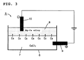
- Fig. 3 is a schematic representation of an example of the principal constitution/feature of an apparatus to be used in carrying out the method of recovering (i.e. method of removing) a metal-fog-forming metal in molten salt according to the present invention.
- the constitution/feature shown in Fig. 3 is the same as that of Ca recovery means 5 shown in Fig. 4 and Fig. 5 , which is to be hereinafter referred to and in which the same reference numerals are used.
- Fig. 3 like in the above-mentioned case shown in Fig.
- the metal-fog-forming metal is represented by Ca, so is the molten salt mixture consisted of one or more of metal-fog-forming metal containing molten salts by a molten CaCl 2 , and the metal-fog-forming metal containing molten alloy by a molten Mg-Ca alloy, and these designations are used in the description which follows.
- the Ca recovery means 5 comprises a Ca recovery vessel 6 and, within this recovery vessel 6, there is held a molten CaCl 2 7 and, thereupon, a molten Mg-Ca alloy 8 is held in contact with the molten salt 7.
- An electrode bar 9 inserted in the molten salt 7 constitutes a positive (+) electrode and an electrode bar 10 inserted in the molten Mg-Ca alloy 8 constitutes a negative (-) electrode.
- a molten CaCl 2 with Ca dissolved therein is first held in a Ca recovery vessel 6. Further, the molten Mg-Ca alloy 8 is held onto the thus-held molten salt 7 to be in contact with the molten salt 7.
- a voltage below the decomposition voltage for CaCl 2 is applied so that the electrode bar 10 inserted in the molten Mg-Ca alloy 8 may serve as a negative (-) electrode and the electrode bar 9 inserted in the molten salt 7 as a positive (+) electrode.
- that portion of the molten Mg-Ca alloy 8 present in the adjacent surface of contact with the molten salt 7 within the Ca recovery vessel 6 functions as a negative (-) electrode relative to the molten salt side (+ electrode side) within the Ca-removing vessel 6 and, therefore, the Ca dissolved therein transfers to the molten Mg-Ca alloy 8 side, as indicated by the arrows in Fig. 3 , and is absorbed thereinto.
- the dissolved Ca in the Ca-removing vessel 6 is recovered (removed).
- FIG. 1 An application example of the method of removing/concentrating a metal-fog-forming metal according to the present invention as shown hereinabove in Fig. 1 is described below under "3: Ti or Ti alloy production process including a Ca removing/concentrating step, and apparatus therefor".
- An application example of the method of removing a metal-fog-forming metal according to the present invention as shown hereinabove in Fig. 3 is described below under "2: Ti or Ti alloy production process including a Ca recovery step, and apparatus therefor".
- Ti or Ti alloy production process including a Ca recovery step, and apparatus therefor
- Fig. 4 is a schematic representation of an example of the constitution/feature of an apparatus to be used in carrying out the Ti or Ti alloy production process including a Ca recovery step according to the present invention.
- the figure shows the case where TiCl 4 alone is used as the raw material.
- this apparatus comprises: a reaction vessel 1 for holding a CaCl 2 -containing molten salt with Ca dissolved therein and for reacting TiCl 4 fed into said molten salt with Ca to form Ti particles; a separation means 2 for separating said Ti particles formed in the molten salt therefrom; an electrolytic cell 3 for electrolyzing the molten salt after separation of said Ti particles therefrom to form Ca on the cathode side; a return means 4 for introducing the Ca formed upon electrolysis into the reaction vessel 1; and a Ca recovery means 5 for removing the Ca dissolved in the molten salt separated in the separation means and to be fed to the electrolytic cell.
- the Ca recovery means 5 shown by way of example in Fig. 4 comprises its essential constituents as shown, and the molten salt 7 separated in the above-mentioned separation means 2 is introduced into the Ca recovery vessel 6. Thereon is held a Ca- and Mg-containing molten alloy 8 (also referred to as "molten Mg-Ca alloy” or as "molten alloy” for short).
- the electrode bar 9 inserted in the molten salt 7 constitutes a positive (+) electrode and the electrode bar 10 inserted in the molten Mg-Ca alloy 8 constitutes a negative (-) electrode.
- the electrolytic cell 3 comprises a piping-like (cylindrical) electrolytic cell vessel 3a elongated in one direction and intended for holding a CaCl 2 -containing molten salt, and likewise, cylindrical anode 11 and a round column-shaped cathode 12, each disposed within the electrolytic cell vessel 3a along the length-wise direction of the vessel 3a.
- One end (bottom plate 13), in a lengthwise direction, of the electrolytic cell vessel 3a is equipped with a molten salt supply port 14, and the other end (cover plate 15) is equipped with a molten salt extraction port 16.
- the surface of the anode 11 and the surface of the cathode 12 are disposed substantially vertically in a facing relation with each other and, further, a partition wall 17 is disposed between the anode 11 and cathode 12 so as to inhibit the Ca formed by electrolysis of the molten salt from passing therethrough.
- a cooling device 18 is provided surrounding the outside surface of the anode 11.
- a decanter type centrifuge (high-temperature decanter) 19 and a separating vessel 20 are used as a separation means 2.
- the molten salt fed from the electrolytic cell 3 via a return means 4 is first held in a reaction vessel 1 and the TiCl 4 fed through a TiCl 4 supply port 21 is caused to react with the Ca in the molten salt to form Ti particles in the molten salt.
- the "reduction step" is carried out.
- the molten salt held in the reaction vessel 1 is not at rest but is gradually moving downward from the upper part of the reaction vessel 1 toward the bottom and, during the downward movement, TiCl 4 as raw material is reduced by the Ca in the molten salt to form Ti particles.
- TiCl 4 as raw material
- the other metal chlorides are also reduced by Ca, as mentioned above, and, therefore, by preliminarily adding predetermined amounts of such metal chlorides to TiCl 4 , it becomes possible to formTi alloy particles and finally produce a Ti alloy.
- the Ti particles formed in the reduction step are separated from the molten salt in the "separation step".
- the separation of the Ti particles from the molten salt can be realized also within the reaction vessel but, in this case, the process is carried out batch-wise. Therefore, for enhancing productivity, it is recommended, for example, that the molten salt with Ca dissolved therein be continuously fed using a reaction vessel of the type shown in Fig. 4 and the formed Ti particles be extracted out of the reaction vessel and separated from the molten salt outside the vessel.
- the Ti particles are first separated and recovered in the high-temperature decanter 19 and then the molten salt adhering to the Ti particles is removed in the separating vessel 20.
- the decanter type centrifuge is a centrifuge of the type such that a suspended substance is caused to settle by centrifugation by rotating a rotary cylinder at a high speed and enables high-speed treatment and has high dehydration performance.
- a type allowing high-temperature treatment has also already been developed and can be used as the high-temperature decanter 19 in this separation step.
- the Ti particles taken out of the high-temperature decanter 19 are heated and melted by plasma emitted from a plasma torch 22 in the separation vessel 20, and the melt is cast into a mold 23 to give a Ti ingot 24.
- the molten salt separated from Ti particles may possibly contain Ti particles. Therefore, returning of this adherent molten salt to the electrolysis step may possibly cause problems; it is therefore desirable that it be returned to the reaction vessel 1, as indicated in Fig. 4 .
- a certain amount of Ca remains in the adherent molten salt, so that it is reasonable to return it to the reaction vessel 1 from the viewpoint of effective Ca utilization as well.
- the molten salt reduced in Ca concentration as separated in said high-temperature decanter 19 is sent to the "Ca recovery step". Namely, said molten salt is introduced into the Ca recovery vessel 6 and kept in contact with the molten Mg-Ca alloy 8 and a voltage is applied so that the electrode bar on the molten alloy side may serve as a negative (-) electrode and the electrode bar on the molten salt side as a positive (+) electrode.
- the applied voltage on that occasion is lower than the decomposition voltage for CaCl 2 . It becomes possible thereby to cause the Ca dissolved in CaCl 2 to be rapidly absorbed into the molten alloy without allowing decomposition of CaCl 2 and rapidly send the molten salt decreased in Ca concentration to the electrolysis step. Since the Ca concentration in the molten salt is reasonably lowered, the back reaction is suppressed.
- iron or a like metal be used as the negative (-) electrode and a graphite electrode or a like insoluble electrode as the positive (+) electrode.
- the limiting current results from the transfer of Ca from the molten salt side (+ electrode side) to the molten alloy side (- electrode side) and the intensity thereof depends on the concentration of Ca dissolved in CaCl 2 , and the limiting current decreases as the Ca concentration decreases.
- the Ca concentration was about 0.01% by mass when the limiting current density was 0.14 A/cm 2 .
- the voltage applied at a level lower than 3.2 V namely, voltage below the decomposition voltage for CaCl 2
- the lower limit to the applied voltage is not particularly specified. For effective Ca removal, however, it is desirable that the applied voltage be not lower than 0.01 V.
- the molten salt reduced in Ca concentration in the Ca recovery step is sent to the "electrolysis step” and electrolyzed to form Ca, whereupon the Ca concentration in the molten salt is increased.
- the molten salt is first fed into and held in the space between the cathode 12 and partition wall 17 in the electrolytic cell 3. Since the electrolytic cell 3 has a shape elongated in one direction (in the example shown, a piping-like (cylindrical) shape elongated in a vertical direction), it is possible to provide the molten salt in the vicinity of the surface of the cathode 12 with a flow rate in one direction and cause the molten salt to flow in one direction in the vicinity of the surface of the cathode 12 by continuously or intermittently feeding the molten salt from one end of the electrolytic cell 3 to the space between the anode 11 and cathode 12.
- the feeding of the molten salt is generally carried out continuously. Depending on the subsequent step and/or other factors, the feeding may be carried out intermittently, namely the feeding of the molten salt may be temporarily halted and then resumed.
- the molten salt is electrolyzed. While the molten salt is allowed to flow in one direction in the vicinity of the surface of the cathode 12, the molten salt is electrolyzed to form Ca on the cathode surface. Since the electrolytic cell 3 has a shape elongated in one direction and, further, in the example shown in Fig.
- the distance between the anode 11 and cathode 12 is set to be relatively short so that the electrolysis voltage may be suppressed to a low level, it is possible to effectively draw out only the molten salt enriched in Ca while inhibiting the mixing of the Ca-rarified molten salt in the vicinity of the molten salt supply port 14 with the Ca-enriched molten salt in the vicinity of the molten salt extraction port 16 by electrolysis.
- the anode surface and cathode surface are disposed substantially vertically in a facing relation with each other while the molten salt in the vicinity of the cathode surface is given a flow rate in one direction and, therefore, the direction of flow of the molten salt is vertical and the chlorine gas generated on the anode side readily floats up to the surface and can be recovered with ease.
- a large amount of the molten salt is treated continuously, so that it is preferable to effectively carry out heat removal in the electrolytic cell. More specifically, it is desirable, for example, that a cooling device be disposed in the central portion of the cathode for removing the heat of reaction from inside the cathode.
- a tube-type heat exchanger for instance, is suited for use as the cooling device.
- cooling device heat exchanger
- the heat removal efficiency is further enhanced.
- the cooling device 18 disposed so as to surround the anode 11 is an example of such cooling device.
- the Ca formed upon electrolysis in the electrolysis step is introduced, either alone or together with the molten salt, into the reaction vessel via the "return step".
- the molten salt increased in Ca concentration in the electrolytic cell is obtained and the Ca is introduced, together with the molten salt, into the reaction vessel via the return step.
- an electrolytic cell having a constitution/feature such that the Ca formed upon electrolyzing the molten salt can be recovered as such, namely as Ca alone (including, however, the condition such that a slight amount of the molten salt is admixed in the Ca) it is possible to employ, in the Ti or Ti production process according to the present invention, a mode of embodiment such that the Ca formed by electrolysis is introduced, while being dissolved in a molten salt, into the reaction vessel.
- the molten salt is not utilized as a transfer medium for Ca in the return step but the Ca formed is transferred as such to a site in the vicinity of the reaction vessel and dissolved there in a separately prepared molten salt and then introduced into the reaction vessel; a reduction in transfer cost can be then expected.
- Fig. 5 is a schematic representation of another example of the constitution/feature of an apparatus to be used in carrying out the Ti or Ti alloy production process including a Ca recovery step according to the present invention.
- This apparatus is a modification to the apparatus shown in Fig. 4 that is made by further providing a regulating vessel 25 for introducing the molten salt in the electrolytic cell 3 thereinto and bringing the same into contact with a Ca supply source to render the Ca concentration in the molten salt constant and, thereafter, feeding the resulting molten salt to the reaction vessel 1.
- the production process shown in Fig. 5 is a modification of the Ti or Ti alloy production process according to the present invention and includes the step of "introducing the molten salt increased in Ca concentration in the electrolysis step into a regulating vessel provided with a Ca supply source and bringing the molten salt with the Ca supply source to thereby render the Ca concentration in the molten salt constant and feeding the resulting molten salt to the reduction step".
- the Ca concentration in the molten salt enriched in Ca in the electrolysis step varies with certain changes in electrolysis conditions in the electrolytic cell 3. Therefore, when the molten salt subjected to electrolysis treatment in the electrolytic cell 3 is directly introduced into the reaction vessel 1, the Ca concentration is not always maintained at a constant level and, therefore, the formation of titanium subchlorides and decreases in current efficiency due to the back reaction, among others, may occur, as mentioned hereinabove, and, in some instances, the TiCl 4 reduction reaction efficiency may be lowered and/or the operation may become difficult to carry out stably.
- the molten salt increased in Ca concentration by using the electrolytic cell 3 in the electrolysis step is introduced into the regulating vessel 25 provided with a Ca supply source 26 and brought into contact with the Ca supply source 26 and thereby rendered constant in Ca concentration; the resulting molten salt can be used for reducing TiCl 4 in the reduction step.
- the flow rate of the adherent molten salt separated from Ti particles in the separation vessel 20 is very low as compared with the flow rate of the molten salt introduced from the electrolytic cell 3 into the reaction vessel 1 via the regulating vessel 25, so that the adherent molten salt may be returned directly to the reaction vessel 1, as mentioned above. It is preferable, however, to once introduce it into the regulating vessel 25 and, after rendering the Ca concentration constant, introduce the same into the reaction vessel 1, as shown in Fig. 3 .
- molten metallic Ca and molten alloys containing Ca at relatively high content levels such as molten Mg-Ca alloy.
- molten metallic Ca or a molten Mg-Ca alloy for instance, is caused to float on the molten salt 27 increased in Ca concentration and introduced into the regulating vessel 25 and such Ca supply source 26 and the molten salt 27 are kept in contact with each other.
- Ca concentration in the molten salt 27 is lower than the saturation solubility thereof, Ca is supplied from the Ca supply source 26 to the molten salt 27 and, in this manner, the Ca concentration can be maintained at a level in the vicinity of the saturation solubility.
- the metallic Ca floats up to the surface and is separated in the regulating vessel 25 owing to the specific gravity difference and, thus, the Ca concentration can be maintained at a level in the vicinity of the saturation solubility. Furthermore, by controlling the temperature of the molten salt 27 on the occasion of extraction from the regulating vessel 25 to a constant level, it becomes possible to control the Ca concentration at a constant level in the vicinity of the saturation solubility at that temperature.
- the electrolysis in the electrolytic cell 3 is carried out to an extent such that the Ca concentration exceeds the saturation solubility, metallic Ca may precipitate out within the electrolytic cell 3, possibly causing such a trouble as electrolytic cell obstruction. Therefore, in increasing the Ca concentration in the electrolytic cell 3, it is preferable to carry out the operation in a manner such that the electrolysis is carried out under control so that the Ca concentration may be reasonably high but just short of the saturation solubility, and the molten salt high in Ca concentration but lower than the saturation solubility is introduced into the regulating vessel 25 and brought into contact with the Ca supply source 26 to thereby adjust the Ca concentration to a constant level in the vicinity of the saturation solubility.
- the production process according to the present invention is preferably one in which the Ca supply source in the regulating vessel shown in Fig. 5 is specified in manner such that "the molten alloy increased in Ca concentration as a result of absorption of Ca in the Ca recovery step is used as the whole Ca supply source or part of it in the regulating vessel".
- the molten alloy 8 increased in Ca concentration as a result of absorption of Ca in the Ca recovery step (a Ca recovery means 5) is transferred to the regulating vessel 25 for use as the Ca supply source 26.
- the whole Ca supply source 26 may be covered by the molten alloy transferred from the Ca recovery step or the molten alloy may be used as part of the Ca supply source 26 when insufficient in quantity.
- the Ca removed from the molten salt separated in the high-temperature decanter 19 and to be sent to the electrolysis step so as to suppress the back reaction can be utilized efficiently.
- the Ti or Ti alloy production apparatus is an apparatus to be used in carrying out the Ti or Ti alloy production process including such a Ca recovery step as mentioned above and the constitution/feature thereof is as schematically shown in Fig. 4 .
- the functions of the respective structural elements are the same as mentioned above and, when this apparatus is used, the Ti or Ti alloy production process (including the mode of embodiment 1a) according to the present invention can be properly carried out.
- Fig. 6 is a schematic representation of the constitution/feature of an apparatus to be used in carrying out the Ti or Ti alloy production process including a Ca removing/concentrating step according to the present invention.
- a Ca removing/concentrating step according to the present invention.
- the apparatus comprises: a reaction vessel 1 for holding a CaCl 2 -containing molten salt with Ca dissolved therein and allowing TiCl 4 fed into the molten salt to react with the Ca to form Ti particles; a separation means 2 for separating the Ti particles formed in the molten salt from the molten salt; an electrolytic cell 3 for electrolyzing the molten salt after separation of the Ti particles to form Ca on the cathode side; a return means 4 for introducing the Ca formed by electrolysis into the reaction vessel 1; and a Ca removing/concentrating unit 28 for removing the Ca dissolved in the molten salt that is separated by the separation means (high-temperature decanter) and is to be fed to the electrolytic cell 3, and for simultaneously increasing the concentration of Ca dissolved in the molten salt separated
- the Ca removing/concentrating unit 28 whose main parts are shown in the figure comprises a Ca removing/concentrating vessel 28a, wherein a molten CaCl 2 is held in the vessel 28a in a condition separated into a Ca-concentrating region 29 and a Ca-removing region 30 by a partition wall 31 and, thereon, a molten Mg-Ca alloy 8 is held in contact with either portion of the molten salt that are present in the Ca-concentrating region 29 and Ca-removing region 30.
- an electrode plate 33 for applying a voltage below the decomposition voltage for CaCl 2 so that it may serve as a positive (+) electrode against an electrode plate 34 on the molten salt side in the Ca-concentrating region 29.
- the Ca-concentrating region 29 and Ca-removing region 30 are separated from each other by the partition wall 31, the constitution/feature thereof is not limited to this. Thus, for example, both regions may be separated from each other by use of two independent, detachable vessels.
- the difference from the use of the apparatus shown in. Fig. 4 lies in the destination of transfer of the molten salt separated from Ti particles in the separation step and the treatment at that destination.
- the molten salt decreased in Ca concentration as being separated in the high-temperature decanter 19 is sent to the Ca-removing region 30 in the Ca removing/concentrating vessel 28a provided in the Ca removing/concentrating unit 28 via Route La, as shown in Fig. 6 , while the adherent molten salt separated from Ti particles in the separation vessel 22 is sent to the Ca-concentrating region 29 in the Ca removing/concentrating vessel 28a via Route Lb.
- a voltage below the decomposition voltage for CaCl 2 is applied via the electrode plate 33 and electrode plate 34 so that the electrode plate disposed on the molten salt side in the Ca-removing region 30 may serve as a positive (+) electrode against the electrode plate 34 disposed on the molten salt side in the Ca-concentrating region 29.
- This voltage application causes a molten Mg-Ca alloy 32 existing in the vicinity of the contact surface with the molten salt in the Ca-removing region 30 to function as a negative (-) electrode relative to the molten salt side (+ electrode side) in the Ca-removing region 30, so that the dissolved Ca transfers to the molten Mg-Ca alloy 32 side, as indicated by the arrows given in the Ca removing/concentrating vessel 28a in Fig. 6 , and absorbed into the alloy.
- the dissolved Ca in the Ca-removing region 30 is removed and the Ca concentration in the Mg-Ca alloy 32 increases.
- the molten Mg-Ca alloy 32 in the vicinity of the contact surface with the molten salt in the Ca-concentrating region 29 functions as a positive (+) electrode relative to the molten salt side (- electrode side) in the Ca-concentrating region 29. Therefore, the Ca in the molten Mg-Ca alloy 32 transfers to the molten salt side in the Ca-concentrating region 29, so that the Ca concentration in the Ca-concentrating region 29 increases.
- That the voltage to be applied is selected at a level lower than the decomposition voltage for CaCl 2 is to avoid the formation of Ca in case of decomposition of CaCl 2 .
- the electrodes for the voltage application mentioned above it is recommended that iron or a like metal be used as the negative (-) electrode and a graphite electrode or a like insoluble electrode as the positive (+) electrode, like in the case of the electrode bars to be mounted on the above-mentioned Ca recovery vessel 6 (shown in Fig. 4 and Fig. 5 ).
- the Ca removal and concentration treatments are carried out simultaneously in the manner mentioned above, and the Ca dissolved in the molten salt in the Ca-removing region 30 is removed and the Ca concentration in the molten salt in the Ca-concentrating region 29 increases.
- Route Lc disposed between Route La and Route Lb is the route for taking a balance of the amounts of the portion of the molten salt in the Ca-removing region 30 and those in the Ca-concentrating region 29.
- Route La and Route Lb themselves are not able to take a balance of the amounts of the molten salt in the Ca-removing region 30 and those in the Ca-concentrating region 29, with a result that it is not possible anymore to continuously carry out the Ca removal and concentration treatments in the Ca removing/concentrating unit 28. Therefore, part of the molten salt separated in the high-temperature decanter 19 is sent, via Route Lc, to the Ca-concentrating region 29 so that the treatments mentioned above may be carried out continuously.
- the molten salt deprived of Ca in the Ca removing/concentrating unit 28 is sent to the "electrolysis step". Since that molten salt has been deprived of Ca, a so-called back reaction, namely the reaction of Ca in the molten salt with chlorine formed by electrolysis, is suppressed and the Ca formation by electrolysis can be executed efficiently.
- the molten salt in the Ca-concentrating region 29 is returned to the reduction step. Since the remaining Ca in the adherent molten salt has been concentrated and has an increased Ca concentration, it is effective in enhancing the efficiency of the TiCl 4 reduction reaction.
- the Ca formed by electrolysis in the electrolysis step is introduced, either alone or together with the molten salt, into the reaction vessel via the "return step".
- the dissolved Ca in the Ca-removing region 30 be removed and, at the same time, the concentration of the dissolved Ca in the Ca-concentrating region 29 be increased at an "applied voltage lower than 3.2 V (namely, voltage below the decomposition voltage for CaCl 2 )".
- the lower limit to the applied voltage is not particularly specified.
- the applied voltage be not lower than 0.01 V.
- Fig. 7 is a schematic representation of another example of the constitution/feature of an apparatus to be used in carrying out the Ti or Ti alloy production process including a Ca removing/concentrating step according to the present invention.
- This apparatus is a modification to the above-mentioned apparatus shown in Fig. 6 that is made by further providing a regulating vessel 25 for introducing thereinto the molten salt in the electrolytic cell 3 and bringing the same into contact with a Ca supply source to thereby render the Ca concentration in that molten salt constant, and for thereafter feeding the resulting molten salt into the reaction vessel 1.
- the Ti or Ti alloy production process according to the present invention is desirably one in which "the molten salt increased in Ca concentration in the electrolysis step is introduced into a regulating vessel provided with a Ca supply source and the molten salt is brought into contact with the Ca supply source to render the Ca concentration in the molten salt constant, and thereafter, the resulting molten salt is sent to the reduction step".
- the Ti or Ti alloy production apparatus is an apparatus to be used in carrying out the above-mentioned Ti or Ti alloy production process including such a Ca removing/concentrating step, and the constitution/feature thereof and the functions of the respective structural elements are as schematically shown in Fig. 6 .
- this apparatus is used, the Ti or Ti alloy production process including such a Ca removing/concentrating step according to the present invention can be properly carried out.
- chlorine (Cl 2 ) is generated as byproduct on the anode side upon electrolysis of the molten salt in the above-mentioned electrolysis step, and this Cl 2 , when allowed to react with titanium oxide (TiO 2 ), gives TiCl 4 . Therefore, the Cl 2 formed on the anode side with the progress of electrolysis of the molten salt is caused to react with a titanium ore to form TiCl 4 and this TiCl 4 , after purification by distillation, is used as the raw material in the production of Ti or a Ti alloy.
- the Cl 2 formed on the anode side is caused to react with a mixture of TiO 2 and metal oxide (s) because at least one metal is added as an alloy element, to give a metal chloride mixture including TiCl 4 , which can be used as the raw material.
- the method ofremoving/concentrating a metal-fog-forming metal in a molten salt according to the present invention can remove the metal-fog-forming metal dissolved in a molten salt mixture consisted of one or more of metal-fog-forming metal containing molten salts from one portion of the molten salt mixture and transfer the same to the other portion of the molten salt mixture for increasing the concentration thereof in that mixture.
- This method can be carried out easily and properly using the apparatus according to the present invention.
- the method of removing/concentrating a metal-fog-forming metal in a molten salt and the apparatus therefor can be expected to be utilized as one of means for treating a molten salt in various industrial fields in which metal-fog-forming metal containing molten salts, the metal-fog-forming metal being such as Ca or Na, are handled. Inparticular, they can be effectively utilized in the production of Ti by Ca reduction.
- the Ti or Ti alloy production process according to the present invention makes it possible to remove (recovery) the Ca dissolved in the molten salt to be fed to the electrolytic cell and thereby aim at enhancing the Ca formation efficiency in electrolyzing the molten salt. Further, the process can contribute not only to increase the Ca concentration in the molten salt to be fed to the reaction vessel, simultaneously with the Ca removal (recovery), while allowing to enhance the efficiency of the Ca formation, but also to enhance the efficiency of the TiCl 4 reduction reaction and, when a regulating vessel is used, the process can make it possible to inhibit the fluctuation of and maintain at a high level the Ca concentration in the molten salt to be fed into the reaction vessel.
- the process makes it possible to continuously treat a large quantity of a CaCl 2 -containing molten salt and increase the feeding rate of Ca to the reaction vessel and thereby it becomes possible to efficiently carry out the Ca formation in electrolysis of the molten salt and the reduction of TiCl 4 and carry out the operation stably on a commercial scale.
- the Ti or Ti alloy production process according to the present invention and the production apparatus according to the present invention which makes it possible to carry out that process easily and properly can be effectively utilized in the production of Ti or a Ti alloy by reduction with Ca.
Landscapes
- Chemical & Material Sciences (AREA)
- Engineering & Computer Science (AREA)
- Metallurgy (AREA)
- Materials Engineering (AREA)
- Organic Chemistry (AREA)
- Geology (AREA)
- General Life Sciences & Earth Sciences (AREA)
- Environmental & Geological Engineering (AREA)
- Life Sciences & Earth Sciences (AREA)
- Manufacturing & Machinery (AREA)
- Mechanical Engineering (AREA)
- Chemical Kinetics & Catalysis (AREA)
- Electrochemistry (AREA)
- Electrolytic Production Of Metals (AREA)
- Manufacture And Refinement Of Metals (AREA)
Applications Claiming Priority (3)
| Application Number | Priority Date | Filing Date | Title |
|---|---|---|---|
| JP2006066132A JP2007239073A (ja) | 2006-03-10 | 2006-03-10 | 溶融塩中メタルフォグ形成金属の除去及び高濃度化方法と装置 |
| JP2006065838A JP4510769B2 (ja) | 2006-03-10 | 2006-03-10 | Ti又はTi合金の製造方法及び装置 |
| PCT/JP2007/054633 WO2007105616A1 (fr) | 2006-03-10 | 2007-03-09 | PROCEDE D'EXTRACTION / DE CONCENTRATION DE METAL FORMANT UN BROUILLARD METALLIQUE PRESENT DANS UN SEL FONDU, APPAREIL CORRESPONDANT, PROCEDE ET APPAREIL DE PRODUCTION DE Ti OU D'ALLIAGE DE Ti AU MOYEN DE CEUX-CI |
Publications (1)
| Publication Number | Publication Date |
|---|---|
| EP1995353A1 true EP1995353A1 (fr) | 2008-11-26 |
Family
ID=38509439
Family Applications (1)
| Application Number | Title | Priority Date | Filing Date |
|---|---|---|---|
| EP07738118A Withdrawn EP1995353A1 (fr) | 2006-03-10 | 2007-03-09 | PROCEDE D'EXTRACTION / DE CONCENTRATION DE METAL FORMANT UN BROUILLARD METALLIQUE PRESENT DANS UN SEL FONDU, APPAREIL CORRESPONDANT, PROCEDE ET APPAREIL DE PRODUCTION DE Ti OU D'ALLIAGE DE Ti AU MOYEN DE CEUX-CI |
Country Status (7)
| Country | Link |
|---|---|
| US (1) | US20090114546A1 (fr) |
| EP (1) | EP1995353A1 (fr) |
| AU (1) | AU2007225815A1 (fr) |
| CA (1) | CA2645103A1 (fr) |
| EA (1) | EA200870343A1 (fr) |
| NO (1) | NO20083515L (fr) |
| WO (1) | WO2007105616A1 (fr) |
Families Citing this family (4)
| Publication number | Priority date | Publication date | Assignee | Title |
|---|---|---|---|---|
| JP2007084847A (ja) * | 2005-09-20 | 2007-04-05 | Sumitomo Titanium Corp | Tiの製造方法および装置 |
| JP4940109B2 (ja) * | 2007-11-12 | 2012-05-30 | 株式会社大阪チタニウムテクノロジーズ | 溶融物中のTi粉濃縮方法および濃縮装置 |
| RU2504591C2 (ru) * | 2011-08-12 | 2014-01-20 | Федеральное государственное автономное образовательное учреждение высшего профессионального образования Уральский федеральный университет им. первого Президента России Б.Н. Ельцина | ЭЛЕКТРОЛИЗЕР ДЛЯ НАСЫЩЕНИЯ РАСПЛАВА CaCl2 КАЛЬЦИЕМ |
| CN113430578B (zh) * | 2021-07-15 | 2022-10-04 | 浙江睿曦绿业新材料科技有限公司 | 一种铝电解电解质脱钠脱锂装置与方法 |
Family Cites Families (6)
| Publication number | Priority date | Publication date | Assignee | Title |
|---|---|---|---|---|
| US2205854A (en) * | 1937-07-10 | 1940-06-25 | Kroll Wilhelm | Method for manufacturing titanium and alloys thereof |
| US2845386A (en) * | 1954-03-16 | 1958-07-29 | Du Pont | Production of metals |
| US2835567A (en) * | 1954-11-22 | 1958-05-20 | Du Pont | Method of producing granular refractory metal |
| FR2582019B1 (fr) | 1985-05-17 | 1987-06-26 | Extramet Sa | Procede pour la production de metaux par reduction de sels metalliques, metaux ainsi obtenus et dispositif pour sa mise en oeuvre |
| JP4395386B2 (ja) | 2003-10-10 | 2010-01-06 | 株式会社大阪チタニウムテクノロジーズ | Ca源の循環によるTi又はTi合金の製造方法 |
| JP2005133196A (ja) | 2003-10-10 | 2005-05-26 | Sumitomo Titanium Corp | 溶融塩の循環によるTi又はTi合金の製造方法 |
-
2007
- 2007-03-09 US US12/224,843 patent/US20090114546A1/en not_active Abandoned
- 2007-03-09 WO PCT/JP2007/054633 patent/WO2007105616A1/fr active Application Filing
- 2007-03-09 AU AU2007225815A patent/AU2007225815A1/en not_active Abandoned
- 2007-03-09 EA EA200870343A patent/EA200870343A1/ru unknown
- 2007-03-09 CA CA002645103A patent/CA2645103A1/fr not_active Abandoned
- 2007-03-09 EP EP07738118A patent/EP1995353A1/fr not_active Withdrawn
-
2008
- 2008-08-13 NO NO20083515A patent/NO20083515L/no not_active Application Discontinuation
Non-Patent Citations (1)
| Title |
|---|
| See references of WO2007105616A1 * |
Also Published As
| Publication number | Publication date |
|---|---|
| US20090114546A1 (en) | 2009-05-07 |
| AU2007225815A1 (en) | 2007-09-20 |
| NO20083515L (no) | 2008-10-06 |
| WO2007105616A1 (fr) | 2007-09-20 |
| EA200870343A1 (ru) | 2009-02-27 |
| CA2645103A1 (fr) | 2007-09-20 |
Similar Documents
| Publication | Publication Date | Title |
|---|---|---|
| Suzuki | Direct reduction processes for titanium oxide in molten salt | |
| NZ527658A (en) | Removal of oxygen from metal oxides and solid solutions by electrolysis in a fused salt | |
| CN108138343B (zh) | 利用电解还原和电解精炼工序的金属精炼方法 | |
| JP5183498B2 (ja) | ケイ素の電解製造及び精練方法 | |
| EP1942210A1 (fr) | PROCÉDÉ D ÉLECTROLYSE DE SEL FONDU, PILE ÉLECTROLYTIQUE, ET PROCÉDÉ DE PRODUCTION DE Ti À L AIDE DUDIT PROCÉDÉ | |
| WO2005103338A1 (fr) | Production d'alliages de fer/titane | |
| EP1995353A1 (fr) | PROCEDE D'EXTRACTION / DE CONCENTRATION DE METAL FORMANT UN BROUILLARD METALLIQUE PRESENT DANS UN SEL FONDU, APPAREIL CORRESPONDANT, PROCEDE ET APPAREIL DE PRODUCTION DE Ti OU D'ALLIAGE DE Ti AU MOYEN DE CEUX-CI | |
| AU2006224012B2 (en) | Method of high-melting-point metal separation and recovery | |
| EP1944383A1 (fr) | Procédé de production de titane et appareil correspondant | |
| JP4510769B2 (ja) | Ti又はTi合金の製造方法及び装置 | |
| JPH10176296A (ja) | 廃ガス中に過フッ化炭素化合物をともなわないネオジムの電解生成 | |
| EP1876248A1 (fr) | PROCEDE DE PRODUCTION DE Ti OU D'UN ALLIAGE DE Ti ET METHODE D'ELECTROLYSE PAR TRACTION VERS LE HAUT DE LA CATHODE APPLICABLE AUDIT PROCEDE | |
| JP2006274340A (ja) | Ti又はTi合金の製造方法 | |
| JPH02259092A (ja) | カルシウムの製造方法 | |
| WO2010003906A1 (fr) | Procédé de production de cuivre à partir de composés sulfureux | |
| Murphy et al. | Recovery of Lead from Galena by a Leach Electrolysis Procedure | |
| JP2006063359A (ja) | 金属の製造方法および装置 | |
| JP4227113B2 (ja) | 引上げ電解方法 | |
| Sokhanvaran et al. | Advances in Electrometallurgy for Sustainable Metal Production | |
| JP2007239073A (ja) | 溶融塩中メタルフォグ形成金属の除去及び高濃度化方法と装置 | |
| CN115652370A (zh) | 一种利用铝灰渣回收制备铝硅合金的方法 | |
| JPH02503695A (ja) | 塩をベースとする融解方法 |
Legal Events
| Date | Code | Title | Description |
|---|---|---|---|
| PUAI | Public reference made under article 153(3) epc to a published international application that has entered the european phase |
Free format text: ORIGINAL CODE: 0009012 |
|
| 17P | Request for examination filed |
Effective date: 20080808 |
|
| AK | Designated contracting states |
Kind code of ref document: A1 Designated state(s): AT BE BG CH CY CZ DE DK EE ES FI FR GB GR HU IE IS IT LI LT LU LV MC MT NL PL PT RO SE SI SK TR |
|
| STAA | Information on the status of an ep patent application or granted ep patent |
Free format text: STATUS: THE APPLICATION HAS BEEN WITHDRAWN |
|
| 18W | Application withdrawn |
Effective date: 20090204 |