EP1995145B1 - Carriage lateral movement-limiting system - Google Patents
Carriage lateral movement-limiting system Download PDFInfo
- Publication number
- EP1995145B1 EP1995145B1 EP07738256.2A EP07738256A EP1995145B1 EP 1995145 B1 EP1995145 B1 EP 1995145B1 EP 07738256 A EP07738256 A EP 07738256A EP 1995145 B1 EP1995145 B1 EP 1995145B1
- Authority
- EP
- European Patent Office
- Prior art keywords
- bogie
- stopper
- lateral movement
- derailment
- attached
- Prior art date
- Legal status (The legal status is an assumption and is not a legal conclusion. Google has not performed a legal analysis and makes no representation as to the accuracy of the status listed.)
- Expired - Fee Related
Links
Images


Classifications
-
- E—FIXED CONSTRUCTIONS
- E01—CONSTRUCTION OF ROADS, RAILWAYS, OR BRIDGES
- E01B—PERMANENT WAY; PERMANENT-WAY TOOLS; MACHINES FOR MAKING RAILWAYS OF ALL KINDS
- E01B5/00—Rails; Guard rails; Distance-keeping means for them
- E01B5/18—Guard rails; Connecting, fastening or adjusting means therefor
-
- B—PERFORMING OPERATIONS; TRANSPORTING
- B61—RAILWAYS
- B61F—RAIL VEHICLE SUSPENSIONS, e.g. UNDERFRAMES, BOGIES OR ARRANGEMENTS OF WHEEL AXLES; RAIL VEHICLES FOR USE ON TRACKS OF DIFFERENT WIDTH; PREVENTING DERAILING OF RAIL VEHICLES; WHEEL GUARDS, OBSTRUCTION REMOVERS OR THE LIKE FOR RAIL VEHICLES
- B61F9/00—Rail vehicles characterised by means for preventing derailing, e.g. by use of guide wheels
Definitions
- the present invention relates to a bogie lateral movement-limiting system, and particularly relates to a bogie lateral movement-limiting system capable of preventing an occurrence of a second disaster by restricting lateral movements of bogies in case of a derailment due to an earthquake or a gust, etc.
- An overturn prevention system which provides at a lower part of an axle box with a stopper device for restraining a vehicle in case of a derailment so that the vehicle is not brought to contact with tracks (rails) and is not displaced in the lateral direction; as a device for preventing a vehicle from overturning in case of derailment due to a natural disaster, such as an earthquake and a gust, by guiding the vehicle to travel on ballast with sleepers or on roadbed, etc.
- a natural disaster such as an earthquake and a gust
- the turnover prevention system requires the high strength for the axle box to be attached with the stopper device, therefore, the overall weight of the bogie increases; the riding comfort may be adversely affected as the unsprung weight increases; and, furthermore, the rails may be damaged when passing through a point or a turnout.
- FR 2 755 658 A1 discloses a lateral movement-limiting device, which is formed by three runners (patins) in the form of cross beams, which are fixed under the chassis of each vehicle.
- the runners are fixed at each end of the vehicle and in the center.
- Each end of the runners is fitted with stoppers or rollers and the center of each runner is fitted with another stopper or roller.
- the rollers are designed to come into contact with the flanges of the rail, in case of the vehicle being derailed and the runners rest on the rails to support the weight of the vehicle.
- JP 11-036201 A discloses a derailment prevention guard member, which is mounted to the right and left side of sleepers so as to form a pair of right and left derailment prevention guard devices.
- Guard members thereof are L-shaped, wherein the horizontal arms of the L facing each other, i.e. both point to the center of the paired rails The heights of the guard members are set to be the same or slightly higher than the top of the rails.
- the present invention has an object thereof to provide a bogie lateral movement-limiting system capable of effectively restricting lateral movements of a derailed bogie with a simple structure and, particularly, capable of preventing a second disaster by limiting a lateral movement amount of the vehicle body to be within a range of being able to prevent a collision with the opposite train on the double track.
- a bogie lateral movement-limiting system is a system for restricting lateral movements of a bogie when a vehicle traveling on paired right and left rails is derailed.
- the system comprises a derailment prevention guard device laid inside of the paired rails and a lateral movement-limiting device attached to a lower part of the bogie.
- the lateral movement-limiting device has a stopper which extends downward from a position inside of wheels of the bogie and is brought to a slide-contact with an inner surface of the derailment prevention device in case of derailment.
- the stopper is provided within a clearance limit for rolling stock and the derailment prevention guard is provided within a construction gauge.
- the stopper is adjustable to the downward direction.
- a bogie lateral movement-limiting device is the device for restricting lateral movements of a bogie by slidingly contacting with a derailment prevention guards laid inside of paired rails in case of a vehicle derailment.
- the lateral movement-limiting device comprises a stopper which is attached to a lower part of the bogie and has a projection extended downward from a position inside wheels of the bogie, and the projection is brought to a slide-contact with an inner surface of the derailment prevention guard device in case of derailment.
- the bogie lateral movement-limiting device comprises an attachment for the stopper provided to a lower part of the bogie and the stopper provided to the attachment, and the stopper is adjustable to the downward direction of the projection thereof. Furthermore, in the bogie lateral movement-limiting device, the stopper is attached to a lower part of the bogie to be able to adjust the vertical position of the projection thereof.
- a derailment prevention guard device is a pair of right and left derailment prevention guard devices laid respectively along inside of paired rails for restricting lateral movements of a bogie by slidingly contacting with a stopper of a lateral movement-limiting device attached to a lower part of the bogie in case of the vehicle derailment.
- the derailment prevention guard device comprises a fixing member to be attached to the right and left side of sleepers and a T-shaped guard member attached to an upper part of each fixing member. Heights of the guard members are set to be same or slightly higher than the top of the rails.
- the bogie lateral movement-limiting system of the present invention it is easy to provide the stopper within the clearance limit for rolling stock and to provide the derailment prevention guard device within the construction gauge.
- the derailment prevention guard functions to prevent wheels from being derailed, and, when the wheels are derailed by climbing over the derailment prevention guard, the stopper slidingly contacts with the inner side of the derailment prevention guard and lateral movements can be restricted without interfering traveling of the vehicle.
- these stoppers and guards do not interfere the normal traveling of the vehicle.
- a downward projection amount of the stopper adjustable it is also possible to compensate the wheel wear easily.
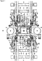
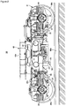
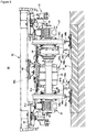
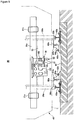
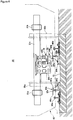
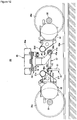
- FIG. 1 to FIG. 3 show an embodiment of a driving bogie used in the bogie lateral movement-limiting system of the present invention: wherein FIG. 1 is a plan view, FIG. 2 is a side view and FIG. 3 is a front view.
- a bogie 30 shown in the present embodiment is a bolsterless bogie for motor car.
- two side beams 31a and 31b being in parallel with right and left rails 60a and 60b and two cross beams 31 c and 31 d being in parallel with sleepers 61 compose a bogie frame 31 having a general H shape in a plan view.
- a traction motor 32 is fixed to each of the cross beams 31c and 31d.
- a rotation force of each of the traction motors 32 is transferred to a wheelset 35 and right and left wheels 36a and 36b via a flexible coupling 33 and a gear unit 34.
- axle boxes are provided to support both end portions of the wheelset 35.
- Axle springs 39 are provided between each axle box 37 and the side beams 31a and 31b.
- the cross beams 31 c and 31 d are provided with disc brake devices 40 in accordance with the respective wheels 36a and 36b.
- Each of the disc brake devices 40 is provided with a wheel tread cleaning device 41 to clean the tread of each of the wheels 36a and 36b.
- a car body 43 is mounted via bolster springs 42 and 42, and the bogie 30 and the car body 43 are connected together by a means of traction device 44 for transmitting a driving force and a braking force.
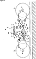
- the traction device 44 is, as shown in FIG. 4 , a single-link type, wherein one link 47 connects between a link bracket on car body 45 attached to a bottom of the underframe 43a of the car body 43 and a link bracket on bogie side 46 attached to a bracket 31f on cross beam 31c. Both end portions 47a and 47b of the link 47 are formed to be ring shapes. In the ring portion of one end portion 47a, a rubber bush 49a provided to a pin 48a in the horizontal direction is force-fitted. The pin 48a is firmly fixed to a lower end of the link bracket on carbody 45 with bolts 50a to be in parallel with the sleepers 61.
- a rubber bush 49b provided to the pin 48b in the horizontal direction is force-fitted.
- the pin 48b is firmly fixed to the end 46a of the link bracket on bogie 46 by bolts 50b to be in parallel with the sleepers 61.
- the link bracket on bogie 46 is attached with a lateral movement-limiting device 52 having a stopper 51 extended downward.
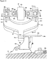
- derailment prevention guards 62a and 62b are provided along inside of the right and left rails 60a and 60b.
- the derailment prevention guards 62a and 62b can be provided to the whole length of the railway, however, particularly, it is preferable that they are provided in a high-speed traveling section.
- the derailment prevention guards 62a and 62b comprise fixing members 64a and 64b attached to right and left of a concrete roadbed on a slab track or the sleepers 61 on a ballasted track and T-shaped guard members 65a and 65b attached to upper parts of the fixing members 64a and 64b. Heights of the guard members 65a and 65b are set to be same or slightly higher than the top of the rails 60a and 60b.
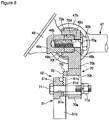
- the first embodiment of the bogie lateral movement-limiting device of the present invention is explained with reference to FIG. 4 to FIG. 9 .
- the lateral movement-limiting device 52 of the first embodiment comprises an attachment for the stopper 70 firmly fixed to the link bracket on bogie 46 and the stopper 51 attached to the lower part of the attachment 70.
- the attachment 70 extends arms 70b and 70b to both sides from the upper part of the base 70a, formed by a square-shaped plate. The distance between the two arms 70b and 70b is slightly longer than a width of the rubber bush 49b.
- a concave groove 70d is provided on the side of the link bracket of the bogie of upper side of the two arms 70b and 70b.
- a concave groove 70d is provided on each of the attachments for mounting on the link bracket 70c to fit the entire pin 48b on the part of the tip 46a of the link bracket on bogie 46.
- the concave groove 70d has a rotation stopper on upper side 70e and another rotation stopper on lower side 70f so that the entire pin 48b and a part of the tip 46a of the link bracket on bogie 46 are fit therein.
- a bolt hole 70g is formed for the bolt 50b to insert.
- the entire pin 48b and a part of the tip 46a of the link bracket on bogie 46, fitted in the concave groove 70d, are firmly fixed to the two arms 70b by the bolt 50b inserted to the bolt hole 70g.
- bolt holes 70h and 70h being long in the vertical direction are formed.
- square-shaped stopper fixing portions 70j and 70j, having an engagement portion 70i having lateral serrations (grooves and ridges) are provided. Between the stopper fixing portions 70j and 70j, a guide groove 70k is formed in vertical direction.
- the stopper 51 is formed to have a T-shape by a square-shaped base portion 51a and projections 51b extended downward from the center of the base portion 51a.
- a sliding-contact portion 51c guided to the guide groove 70k, is provided to extend to the direction of the attachment.
- mounting faces 51d and 51 d having lateral serrations are formed to be engaged with the engagement portion 70i.
- bolt holes 51e and 51 e for bolts 71 and 71 to mount the stopper 51 to the attachment 70 are formed corresponding to the bolt holes 70h and 70h.
- the stopper 51 is integrated by inserting the bolt 71 through the bolt holes 51e and 70h and tightening it with a nut 71a.
- the integrated stopper 51 is attached to the link bracket on bogie 46 by fitting the end portion of the pin 48b and a part of the tip 46a of the link bracket on bogie 46 respectively in the concave groove 70d, inserting the bolt 50b in the bolt holes 70g and 48c of the pin 48b, and tightening with a female screw hole 46b provided to the link bracket on bogie 46.
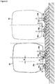
- a side face of the stopper 51 slidingly contacts with the track inner portion 67b of the guard member 65b and the bogie 30 is restricted not to move to the derailment direction any more without interfering traveling of the vehicle.
- a distance between the track inner portion 67b and the side face of the stopper 51 is set to be about 1/2 of an interval of car bodies 43 of trains running on a double track section.
- an actual width of the car body is about 3380mm; therefore, an interval between car bodies in the train coming from the opposite direction becomes about 820mm. Accordingly, by setting the lateral movement limiting width M to 410mm or narrower, a collision between the trains running in the opposite directions can be prevented even if both of the vehicles passing each other on double track are derailed to the inner direction, furthermore, even if the derailed car bodies slightly tilt inside; so that a second disaster caused by a collision of the derailed car bodies can be prevented.
- the lateral movement-limiting device 52 has bolt holes 70h on the attachment 70, a vertical position of the stopper 51 can be easily adjusted. Also, when a wheel diameter becomes smaller due to the wheel turning, by changing the attaching position of the stopper 51 to be higher with respect to the attachment 70, the stopper 51 can be prevented from projecting downward to be lower than the clearance limit for rolling stock L.
- the projection 51b of the stopper 51 can be easily provided at the center position between the wheels; so that one lateral movement-limiting device 52 is effective for derailment in both directions to the right and to the left.
- the same lateral movement-limiting device can be installed to both the driving bogies and trailing bogies because the same shapes of link bracket are provided to trailing bogies without traction motors; so that the number of parts can be reduced and maintainability can be improved.
- the lateral movement-limiting device having the configuration as explained above can be installed easily to the existing bogies without additional member for attaching the stopper device because the existing bogies also have the same attaching structure for the link bracket on bogie and the pin. Also, by fitting the pin 48b and a part of the tip 46a of the link bracket on bogie 46 in the concave groove 70d of the attachment 70 and tightening together by using bolts 50b, a load when lateral movements of the bogie are limited can be received by the pin 48b and the link bracket on bogie 46.
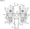
- FIG. 10 A second embodiment of the lateral movement-limiting device of the present invention is explained with reference to FIG. 10 and FIG 11 . Note that, in the following explanations, identical components as those shown in the above first embodiment are given identical reference numbers and detailed explanations thereon are omitted.
- the arm 70b is fixed between the tip 46a and the pin 48b by using the bolts 50b by placing the arm 70b of the attachment 70 between tip 46a of the link bracket on bogie 46 and the pin 48b.
- An upper side rotation stopper 70e and a lower side rotation stopper 70f are provided above and beneath the mounting portion of the tip 46a of the arms 70b.
- Liner 80 inserted between the lower side rotation stopper 70f and the bottom surface of the tip 46a is fixed to a bracket 70m hanging laterally from the lower side rotation stopper 70f.
- the engagement portion 70i on the base portion 70a of the attachment 70 and the engagement face 51 d of the base portion 51a of the stopper 51 is connected by means of serrations.
- Other configurations are almost the same as those in the first embodiment. Note that a means of fixing the tip 46a of the link bracket on bogie 46 and the pin 48b to the attaching arm 70b can be made more compact in the second embodiment comparing with that in the first one.
- FIG. 12 to FIG. 16 show an example of applying to a driving bogie and FIG. 17 and FIG. 18 show an example of applying to a trailing bogie.
- this lateral movement-limiting device 52 fixes the stopper 51 to stopper attaching portions 46c and 46c by bolts 71 and 71, wherein tips 46a and 46a of the link bracket on bogie 46 are extended and both of the extended portions are used as the stopper attaching portions 46c and 46c.
- the pins 48b and 48b are fixed by bolts 50b and 50b.
- an engagement portion 46b and a female screw hole 46e for tightening the bolt 71 are provided on the stopper device attaching face.
- the stopper 51 is formed to be a Y-shape by a pair of attaching arms 51f and 51f extended upward to be attached respectively to both of the stopper attaching portions 46c and 46c and a projection 51b extended downward.
- a bolt hole 51 g being long in the vertical direction is provided for a bolt 71 to be inserted therein, and a face on the side of the stopper attaching portion has an engagement face 51h formed thereon.
- the number of bolts for fixing the stopper 51 can be reduced comparing with that in the first example by attaching the stopper 51 to the stopper attaching portion 46c formed by extending both side portions of the link bracket on bogie46. Furthermore, space between the attaching arms 51f and 51f can be widened , so that strength and stability of the stopper 51 can be improved.
- the lateral movement-limiting device 52 is provided to a bracket 31g of a cross beam 31c of the trailing bogie.
- the reference number 31h indicates a bracket for braking gear of trailing bogie.
- the shape and configuration, etc. of the lateral movement-limiting device 52 are the same as those in the third embodiment shown in FIG. 12 to FIG. 16 .
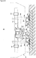
- a lateral movement-limiting device of a fourth embodiment is explained with reference to FIG.19 and FIG.20 .
- the lateral movement-limiting device 52 in this embodiment is made by dividing the stopper in the third embodiment into two members structure: An attachment for the stopper 70 and the stopper 51.
- the attachment 70 comprises a base portion 70a and attaching arms 70b and 70b.
- the stopper 51 comprises a base portion 51a and a projection 51b.
- the attachment 70 is mounted by fixing the attaching arms 70b and 70b using bolts 72 and 72 with tip portions of the stopper attaching portions 46c and 46c fitted in the concave grooves 70d and 70d,.
- the base portion 70a of the attachment 70 has bolt holes 70h and 70h being long in the vertical direction for the bolts 71 and 71 to be inserted, and an engagement portion 70i is formed around each of the bolt hole 70h.
- the engagement portion 70i connects with the engagement face 51d of the stopper 51, and the stopper 51 is fixed to the attachment 70 by bolts 71. Since the stopper 51 and the attachment 70 are in serration engagement, vertical position is easily adjusted.
- a lateral movement-limiting device of a fifth embodiment is explained with reference to FIG. 21 and FIG. 22 .
- the lateral movement-limiting device 52 is mounted to a stopper attaching portion 31e provided to the bracket 31f by bolts 71. Note that the traction motor 32 is supported by the cross beam 31c via the attaching bracket 31f.
- a stopper 90 of the lateral movement-limiting device 52 is formed to be an L-shape and comprises a longitudinal attaching arm 90a corresponding to the stopper attaching portion 31e and a projection 90b extended downward from one end of the attaching arm 90a.
- the stopper 90 is fixed to the stopper attaching portion 31 e by bolts 71 so that the projection 90b is arranged at the center portion in lateral direction.
- a stopper can be attached to the traction motor 32 or an attaching frame thereof, etc. Note that, while a detailed illustration is omitted, by providing an engagement portion on contact faces of the stopper attaching portion 31e and the attaching arm 90a, respectively, in the same way as explained above, positional deviation of the stopper 90 can be prevented. A position of the stopper 90 in the vertical direction can be adjusted by providing long bolt holes on the attaching arm 90a or the stopper attaching portion 31e.
- any type of structure of the bogie may be applied, the stopper may be shaped according to the structure of each type of bogies, and similar stoppers may be provided at several positions.
Description
- The present invention relates to a bogie lateral movement-limiting system, and particularly relates to a bogie lateral movement-limiting system capable of preventing an occurrence of a second disaster by restricting lateral movements of bogies in case of a derailment due to an earthquake or a gust, etc.
- An overturn prevention system has been proposed, which provides at a lower part of an axle box with a stopper device for restraining a vehicle in case of a derailment so that the vehicle is not brought to contact with tracks (rails) and is not displaced in the lateral direction; as a device for preventing a vehicle from overturning in case of derailment due to a natural disaster, such as an earthquake and a gust, by guiding the vehicle to travel on ballast with sleepers or on roadbed, etc. (For example, refer to the
Patent Article 1, i.e. theJapanese Publication Patent No. 3393032B, published on April 7th, 2004 - However, the turnover prevention system as explained above requires the high strength for the axle box to be attached with the stopper device, therefore, the overall weight of the bogie increases; the riding comfort may be adversely affected as the unsprung weight increases; and, furthermore, the rails may be damaged when passing through a point or a turnout.
-
FR 2 755 658 A1 -
JP 11-036201 A - In consideration of the above circumstances, the present invention has an object thereof to provide a bogie lateral movement-limiting system capable of effectively restricting lateral movements of a derailed bogie with a simple structure and, particularly, capable of preventing a second disaster by limiting a lateral movement amount of the vehicle body to be within a range of being able to prevent a collision with the opposite train on the double track.
- The above object is achieved by the subject-matter of the independent claims. A bogie lateral movement-limiting system is a system for restricting lateral movements of a bogie when a vehicle traveling on paired right and left rails is derailed. The system comprises a derailment prevention guard device laid inside of the paired rails and a lateral movement-limiting device attached to a lower part of the bogie. The lateral movement-limiting device has a stopper which extends downward from a position inside of wheels of the bogie and is brought to a slide-contact with an inner surface of the derailment prevention device in case of derailment. The stopper is provided within a clearance limit for rolling stock and the derailment prevention guard is provided within a construction gauge. The stopper is adjustable to the downward direction.
- A bogie lateral movement-limiting device is the device for restricting lateral movements of a bogie by slidingly contacting with a derailment prevention guards laid inside of paired rails in case of a vehicle derailment. The lateral movement-limiting device comprises a stopper which is attached to a lower part of the bogie and has a projection extended downward from a position inside wheels of the bogie, and the projection is brought to a slide-contact with an inner surface of the derailment prevention guard device in case of derailment. The bogie lateral movement-limiting device comprises an attachment for the stopper provided to a lower part of the bogie and the stopper provided to the attachment, and the stopper is adjustable to the downward direction of the projection thereof. Furthermore, in the bogie lateral movement-limiting device, the stopper is attached to a lower part of the bogie to be able to adjust the vertical position of the projection thereof.
- A derailment prevention guard device is a pair of right and left derailment prevention guard devices laid respectively along inside of paired rails for restricting lateral movements of a bogie by slidingly contacting with a stopper of a lateral movement-limiting device attached to a lower part of the bogie in case of the vehicle derailment. The derailment prevention guard device comprises a fixing member to be attached to the right and left side of sleepers and a T-shaped guard member attached to an upper part of each fixing member. Heights of the guard members are set to be same or slightly higher than the top of the rails.
- According to the bogie lateral movement-limiting system of the present invention, it is easy to provide the stopper within the clearance limit for rolling stock and to provide the derailment prevention guard device within the construction gauge. Also, the derailment prevention guard functions to prevent wheels from being derailed, and, when the wheels are derailed by climbing over the derailment prevention guard, the stopper slidingly contacts with the inner side of the derailment prevention guard and lateral movements can be restricted without interfering traveling of the vehicle. Furthermore, by providing the stopper within the clearance limit for rolling stock gauge and providing the derailment guard within the construction gauge, these stoppers and guards do not interfere the normal traveling of the vehicle. Moreover, by setting a downward projection amount of the stopper adjustable, it is also possible to compensate the wheel wear easily.
-
- [
FIG. 1 ] A plan view showing an embodiment of a driving bogie used in the bogie lateral movement-limiting system of the present invention. - [
FIG. 2 ] A side view ofFIG. 1 . - [
FIG. 3 ] A front view ofFIG. 1 . - [
FIG. 4 ] A side view showing a schematic illustration of a driving bogie wherein the first embodiment of the bogie lateral movement-limiting device of the present invention is applied. - [
FIG. 5 ] A front view showing the first embodiment. - [
FIG. 6 ] A front view showing the first embodiment when derailed. - [
FIG. 7 ] A front view showing a key part of the first embodiment. - [
FIG. 8 ] A sectional view along the line 8-8 inFIG. 7 . - [
FIG. 9 ] An explanatory view showing a derailed vehicle and a not-derailed vehicle traveling on the opposite directions on a double track. - [
FIG. 10 ] A front view showing a key part of a second embodiment. - [
FIG. 11 ] A sectional view along the line 11-11 inFIG. 10 . - [
FIG. 12 ] A side view showing a schematic illustration of a driving bogie wherein a third embodiment is applied. - [
FIG. 13 ] A front view of the third embodiment. - [
FIG. 14 ] A front view showing a key part of the third embodiment. - [
FIG. 15 ] A sectional view along the line 15-15 inFIG. 14 . - [
FIG. 16 ] A sectional view along the line 16-16 inFIG. 14 . - [
FIG. 17 ] A side view showing a schematic illustration when the third embodiment is applied to a trailing bogie. - [
FIG. 18 ] A front view ofFIG. 17 . - [
FIG. 19 ] A front view showing a key part of a fourth embodiment. - [
FIG. 20 ] A sectional view along the line 20-20 inFIG. 19 . - [
FIG. 21 ] A side view showing a schematic illustration of a driving bogie wherein a fifth embodiment is applied. - [
FIG. 22 ] A front view of the fifth embodiment. -
- 30...
- bogie
- 31...
- bogie frame
- 31a, 31b...
- side beam
- 31c, 31d...
- cross beam
- 32...
- traction motor
- 35...
- wheelset
- 36a, 36b...
- wheel
- 43...
- car body
- 43a...
- underframe
- 44...
- traction device
- 45...
- link bracket on car body
- 46...
- link bracket on bogie
- 47...
- link
- 48a, 48b...
- pin
- 49a, 49b...
- rubber bush
- 50a, 50b...
- bolt
- 51...
- stopper
- 52...
- lateral movement-limiting device
- 51a...
- base portion
- 51b...
- projection
- 51 c...
- sliding-contact portion
- 51d...
- serration face
- L...
- clearance limit for rolling stock
- M...
- lateral movement-limiting width
-
FIG. 1 to FIG. 3 show an embodiment of a driving bogie used in the bogie lateral movement-limiting system of the present invention: whereinFIG. 1 is a plan view,FIG. 2 is a side view andFIG. 3 is a front view. Abogie 30 shown in the present embodiment is a bolsterless bogie for motor car. In thebogie 30, twoside beams rails cross beams sleepers 61 compose abogie frame 31 having a general H shape in a plan view. Atraction motor 32 is fixed to each of the cross beams 31c and 31d. A rotation force of each of thetraction motors 32 is transferred to awheelset 35 and right and leftwheels flexible coupling 33 and agear unit 34. On both end portions of theside beams wheelset 35. Axle springs 39 are provided between eachaxle box 37 and theside beams disc brake devices 40 in accordance with therespective wheels disc brake devices 40 is provided with a wheeltread cleaning device 41 to clean the tread of each of thewheels bogie frame 31, acar body 43 is mounted via bolstersprings bogie 30 and thecar body 43 are connected together by a means oftraction device 44 for transmitting a driving force and a braking force. - The
traction device 44 is, as shown inFIG. 4 , a single-link type, wherein onelink 47 connects between a link bracket oncar body 45 attached to a bottom of theunderframe 43a of thecar body 43 and a link bracket onbogie side 46 attached to abracket 31f oncross beam 31c. Bothend portions link 47 are formed to be ring shapes. In the ring portion of oneend portion 47a, arubber bush 49a provided to apin 48a in the horizontal direction is force-fitted. Thepin 48a is firmly fixed to a lower end of the link bracket oncarbody 45 withbolts 50a to be in parallel with thesleepers 61. In the ring portion of theother end 47b, arubber bush 49b provided to thepin 48b in the horizontal direction is force-fitted. Thepin 48b is firmly fixed to theend 46a of the link bracket onbogie 46 bybolts 50b to be in parallel with thesleepers 61. The link bracket onbogie 46 is attached with a lateral movement-limitingdevice 52 having astopper 51 extended downward. - Along inside of the right and left
rails derailment prevention guards derailment prevention guards derailment prevention guards members sleepers 61 on a ballasted track and T-shapedguard members members guard members rails - In case the
wheel 36b on one side floats and a flange of thewheel 36b is about to climb over therail 60b due to shakes by an earthquake, etc., as a result that the inner surface of theother wheel 36a slidingly contacts with the rail-side portion 66a of theguard member 65a, derailment of thewheel 36a to the inner side of the track is prevented and the flange of thewheel 36b is prevented from going over therail 60b. As a result, thewheels rails - In case the flange of one
wheel 36b goes over therail 60b and theother wheel 36a goes over thederailment prevention guard 62a to the derailment due to a big shake, it is formed that a side surface of thestopper 51 slidingly contacts with ainner portion 67b of theguard member 65b to restrict further movement of thebogie 30 in the derailment direction without interfering with the vehicle running. Accordingly, lateral movements of the derailedbogie 30 are limited, and derailment to be out of the track outside and an overturn of the vehicle can be prevented, and as a result a second disaster caused by the derailment can be prevented. - The first embodiment of the bogie lateral movement-limiting device of the present invention is explained with reference to
FIG. 4 to FIG. 9 . Note that identical components as those shown inFIG. 1 to FIG. 3 are given identical reference numbers respectively and detailed explanations thereon are omitted in the following description. The lateral movement-limitingdevice 52 of the first embodiment comprises an attachment for thestopper 70 firmly fixed to the link bracket onbogie 46 and thestopper 51 attached to the lower part of theattachment 70. Theattachment 70 extendsarms base 70a, formed by a square-shaped plate. The distance between the twoarms rubber bush 49b. On the side of the link bracket of the bogie of upper side of the twoarms bogie link bracket 70c, aconcave groove 70d is provided to fit theentire pin 48b on the part of thetip 46a of the link bracket onbogie 46. Theconcave groove 70d has a rotation stopper onupper side 70e and another rotation stopper onlower side 70f so that theentire pin 48b and a part of thetip 46a of the link bracket onbogie 46 are fit therein. - On a back of the
concave groove 70d, abolt hole 70g is formed for thebolt 50b to insert. Theentire pin 48b and a part of thetip 46a of the link bracket onbogie 46, fitted in theconcave groove 70d, are firmly fixed to the twoarms 70b by thebolt 50b inserted to thebolt hole 70g. On both sides of thebase portion 70a,bolt holes base portion 70a, square-shapedstopper fixing portions engagement portion 70i having lateral serrations (grooves and ridges) are provided. Between thestopper fixing portions guide groove 70k is formed in vertical direction. - The
stopper 51 is formed to have a T-shape by a square-shapedbase portion 51a andprojections 51b extended downward from the center of thebase portion 51a. At the center of thebase portion 51a, a sliding-contact portion 51c, guided to theguide groove 70k, is provided to extend to the direction of the attachment. On both sides of the sliding-contact portion 51 c, mountingfaces engagement portion 70i. On the mounting faces 51d and 51 d of thebase portion 51a,bolt holes bolts stopper 51 to theattachment 70 are formed corresponding to the bolt holes 70h and 70h. - In the state where the mounting
face 51 d is engaged with a preset position of theengagement portion 70i and theprojection 51b is brought to protrude downward with a preset amount, thestopper 51 is integrated by inserting thebolt 71 through the bolt holes 51e and 70h and tightening it with anut 71a. Theintegrated stopper 51 is attached to the link bracket onbogie 46 by fitting the end portion of thepin 48b and a part of thetip 46a of the link bracket onbogie 46 respectively in theconcave groove 70d, inserting thebolt 50b in the bolt holes 70g and 48c of thepin 48b, and tightening with afemale screw hole 46b provided to the link bracket onbogie 46. - For example, in case that one
wheel 36b goes over therail 60b and theother wheel 36a goes over thederailment prevention guard 62a to result in derailment due to a big quake, a side face of thestopper 51 slidingly contacts with the trackinner portion 67b of theguard member 65b and thebogie 30 is restricted not to move to the derailment direction any more without interfering traveling of the vehicle. - An explanation will be made, with reference to
FIG. 9 , on states of the derailed vehicle in the case where thestopper 51 slidingly contacts with theguard member 65b to restrict thebogie 30 not to move to the derailment direction any more without interfering traveling of the vehicle as explained above and a not-derailed vehicle. Since the lateral movement limiting width M can be set based on a relationship of a position of the trackinner portion 67b of theguard member 65b and a position of the side face of thestopper 51, it is preferable that a distance between the trackinner portion 67b and the side face of thestopper 51 is set to be about 1/2 of an interval ofcar bodies 43 of trains running on a double track section. For example, when a distance between centers of tracks of the double track is 4200mm at minimum in a straight section and a width of the clearance limit for rolling stock is 3400mm, an actual width of the car body is about 3380mm; therefore, an interval between car bodies in the train coming from the opposite direction becomes about 820mm. Accordingly, by setting the lateral movement limiting width M to 410mm or narrower, a collision between the trains running in the opposite directions can be prevented even if both of the vehicles passing each other on double track are derailed to the inner direction, furthermore, even if the derailed car bodies slightly tilt inside; so that a second disaster caused by a collision of the derailed car bodies can be prevented. - Since the lateral movement-limiting
device 52 hasbolt holes 70h on theattachment 70, a vertical position of thestopper 51 can be easily adjusted. Also, when a wheel diameter becomes smaller due to the wheel turning, by changing the attaching position of thestopper 51 to be higher with respect to theattachment 70, thestopper 51 can be prevented from projecting downward to be lower than the clearance limit for rolling stock L. - Furthermore, since the
attachment 70 and thestopper 51 are connected by means of theengagement portion 70i and theserration face 51d and the sliding-contact portion 51c is guided to thegroove 70k, positional deviation of thestopper 51 due to vibration during running etc. can be surely prevented. In addition, when thestopper 51 slidingly contacts with the derailment prevention guard in case of derailment, a load imposed on thestopper 51 can be surely reacted on the engagement faces between theengagement portion 70i and theserration face 51d and on the contact faces between the sliding-contact portion 51c and theguide groove 70k. - Also, by attaching the lateral movement-limiting
device 52 to the link bracket onbogie 46 used for the single-link type traction link, theprojection 51b of thestopper 51 can be easily provided at the center position between the wheels; so that one lateral movement-limitingdevice 52 is effective for derailment in both directions to the right and to the left. Furthermore, as far as the same type bogies are used, the same lateral movement-limiting device can be installed to both the driving bogies and trailing bogies because the same shapes of link bracket are provided to trailing bogies without traction motors; so that the number of parts can be reduced and maintainability can be improved. - Particularly, as far as a single-link type traction link is used on the bogies, the lateral movement-limiting device having the configuration as explained above can be installed easily to the existing bogies without additional member for attaching the stopper device because the existing bogies also have the same attaching structure for the link bracket on bogie and the pin. Also, by fitting the
pin 48b and a part of thetip 46a of the link bracket onbogie 46 in theconcave groove 70d of theattachment 70 and tightening together by usingbolts 50b, a load when lateral movements of the bogie are limited can be received by thepin 48b and the link bracket onbogie 46. - A second embodiment of the lateral movement-limiting device of the present invention is explained with reference to
FIG. 10 andFIG 11 . Note that, in the following explanations, identical components as those shown in the above first embodiment are given identical reference numbers and detailed explanations thereon are omitted. - In the lateral movement-limiting
device 52 of the second embodiment, thearm 70b is fixed between thetip 46a and thepin 48b by using thebolts 50b by placing thearm 70b of theattachment 70 betweentip 46a of the link bracket onbogie 46 and thepin 48b. An upperside rotation stopper 70e and a lowerside rotation stopper 70f are provided above and beneath the mounting portion of thetip 46a of thearms 70b.Liner 80 inserted between the lowerside rotation stopper 70f and the bottom surface of thetip 46a is fixed to abracket 70m hanging laterally from the lowerside rotation stopper 70f. Theengagement portion 70i on thebase portion 70a of theattachment 70 and theengagement face 51 d of thebase portion 51a of thestopper 51 is connected by means of serrations. Other configurations are almost the same as those in the first embodiment. Note that a means of fixing thetip 46a of the link bracket onbogie 46 and thepin 48b to the attachingarm 70b can be made more compact in the second embodiment comparing with that in the first one. - A lateral movement-limiting device in a third embodiment is explained with reference to
FIG. 12 to FIG. 18 .FIG. 12 to FIG. 16 show an example of applying to a driving bogie andFIG. 17 andFIG. 18 show an example of applying to a trailing bogie. InFIG. 12 to FIG. 16 , this lateral movement-limitingdevice 52 fixes thestopper 51 tostopper attaching portions bolts tips bogie 46 are extended and both of the extended portions are used as thestopper attaching portions tip portions pins bolts stopper attaching portion 46c, anengagement portion 46b and afemale screw hole 46e for tightening thebolt 71 are provided on the stopper device attaching face. - The
stopper 51 is formed to be a Y-shape by a pair of attachingarms stopper attaching portions projection 51b extended downward. At an upper part of each of the attachingarms 51f, abolt hole 51 g being long in the vertical direction is provided for abolt 71 to be inserted therein, and a face on the side of the stopper attaching portion has anengagement face 51h formed thereon. - As explained above, the number of bolts for fixing the
stopper 51 can be reduced comparing with that in the first example by attaching thestopper 51 to thestopper attaching portion 46c formed by extending both side portions of the link bracket on bogie46. Furthermore, space between the attachingarms stopper 51 can be improved. - In the same way as in both of the embodiments explained above, positional deviation between the
stopper attaching portion 46c and thestopper 51 is prevented by the engagement, and a vertical position of thestopper 51 can be adjusted by thebolt hole 51g. - An example of applying the lateral movement-limiting device of the third embodiment to a trailing bogie is explained with reference to
FIG. 17 andFIG. 18 . The lateral movement-limitingdevice 52 is provided to abracket 31g of across beam 31c of the trailing bogie. Thereference number 31h indicates a bracket for braking gear of trailing bogie. The shape and configuration, etc. of the lateral movement-limitingdevice 52 are the same as those in the third embodiment shown inFIG. 12 to FIG. 16 . - A lateral movement-limiting device of a fourth embodiment is explained with reference to
FIG.19 andFIG.20 . The lateral movement-limitingdevice 52 in this embodiment is made by dividing the stopper in the third embodiment into two members structure: An attachment for thestopper 70 and thestopper 51. Theattachment 70 comprises abase portion 70a and attachingarms stopper 51 comprises abase portion 51a and aprojection 51b. Theattachment 70 is mounted by fixing the attachingarms 70b using bolts stopper attaching portions concave grooves base portion 70a of theattachment 70 hasbolt holes bolts engagement portion 70i is formed around each of thebolt hole 70h. Theengagement portion 70i connects with theengagement face 51d of thestopper 51, and thestopper 51 is fixed to theattachment 70 bybolts 71. Since thestopper 51 and theattachment 70 are in serration engagement, vertical position is easily adjusted. - A lateral movement-limiting device of a fifth embodiment is explained with reference to
FIG. 21 andFIG. 22 .The lateral movement-limitingdevice 52 is mounted to astopper attaching portion 31e provided to thebracket 31f bybolts 71. Note that thetraction motor 32 is supported by thecross beam 31c via the attachingbracket 31f. - A
stopper 90 of the lateral movement-limitingdevice 52 is formed to be an L-shape and comprises a longitudinal attachingarm 90a corresponding to thestopper attaching portion 31e and aprojection 90b extended downward from one end of the attachingarm 90a. Thestopper 90 is fixed to thestopper attaching portion 31 e bybolts 71 so that theprojection 90b is arranged at the center portion in lateral direction. - As explained above, in the case of a driving bogie provided with a
traction motor 32, a stopper can be attached to thetraction motor 32 or an attaching frame thereof, etc. Note that, while a detailed illustration is omitted, by providing an engagement portion on contact faces of thestopper attaching portion 31e and the attachingarm 90a, respectively, in the same way as explained above, positional deviation of thestopper 90 can be prevented. A position of thestopper 90 in the vertical direction can be adjusted by providing long bolt holes on the attachingarm 90a or thestopper attaching portion 31e. - Note that, in each embodiment, even though it is possible to provide a derailment prevention guard for preventing derailment of a wheel and a derailment prevention guard for the stopper separately and to install them on the different positions, required cost such as construction and installation can be reduced by giving both of the functions to one derailment prevention guard as explained above. Also, any type of structure of the bogie may be applied, the stopper may be shaped according to the structure of each type of bogies, and similar stoppers may be provided at several positions.
Claims (6)
- A bogie lateral movement-limiting system for restricting lateral movements of a bogie (30) in case of a derailment of a vehicle traveling on paired rails (60a, 60b) whereby the system comprises a derailment prevention guard device (62a, 62b) to be laid along inside of the paired rails (60a, 60b);- and a lateral movement-limiting device (52) adapted to be attached to a cross beam (31c) of a bogie frame (31);- wherein the lateral movement-limiting device (52) has a stopper (51) which is to be extended downward from a proximate center position between wheels (36a, 36b) of the bogie (30) in width direction and which slidingly contacts with an inner surface of the derailment prevention guard device (62a, 62b) in case of derailment.
- The bogie lateral movement-limiting system as set forth in claim 1, wherein the stopper (51) is provided within clearance limit for rolling stock and the derailment prevention guard (62a, 62b) is provided within construction gauge.
- The bogie lateral movement-limiting system as set forth in claim 1, wherein the stopper (51) is provided to be adjustable in a downward projection amount thereof.
- A bogie lateral movement-limiting device (52) for use in a bogie lateral movement-limiting system according to anyone of the foregoing claims, for restricting lateral movements of a bogie (30) by slidingly contacting with a derailment prevention guard (62a, 62b) to be laid along inside of paired rails (60a, 60b) in case of a derailment of vehicle traveling on the paired rails (60a, 60b); wherein the lateral movement-limiting device (52) comprises a stopper (51) which is adapted to be attached to a cross beam (31c) of a bogie frame (31) and which has a projection (51b) to be extended downward from a proximate center position between the wheels (36a, 36b) of the bogie (30) in a width direction; whereby the projection (51 b) contacts slidingly with an inner surface of the derailment prevention guard device (62a, 62b) in case of derailment,wherein the stopper (51) is mounted on an attachment (70) to be attached to the cross beam (31c) of the bogie frame (31); and wherein the stopper (51) is adjustable in a downward projection amount.
- The bogie lateral movement-limiting device (52) as set forth in claim 4, wherein the stopper (51) is adapted to be attached to the cross beam (31c) of the bogie frame (31) of the bogie (30) to be adjustable in a downward projection amount.
- A derailment prevention guard device (62a, 62b) fur use in a bogie lateral movement-limiting system according to anyone of claims 1 to 3, being a pair of right and left derailment prevention guards (62a, 62b) to be laid respectively along inside of paired right and left rails (60a, 60b) for restricting lateral movements of a bogie (30) by slidingly contacting with a stopper (51) of a lateral movement-limiting device (52) adapted to be attached to a cross beam (31c) of a bogie frame (31) in case of a derailment of a vehicle traveling on the rails (60a, 60b): wherein each of the derailment prevention guards (62a, 62b) comprises fixing members (64a, 64b) to be attached to the right and left side of sleepers (61) and a T-shaped guard member (65a, 65b) attached to the upper part of each of the fixing member (64a, 64b); and heights of the guard members (65a, 65b) are set to be same or slightly higher than the top of the rails (60a, 60b).
Applications Claiming Priority (2)
| Application Number | Priority Date | Filing Date | Title |
|---|---|---|---|
| JP2006066974 | 2006-03-13 | ||
| PCT/JP2007/054784 WO2007105672A1 (en) | 2006-03-13 | 2007-03-12 | Carriage lateral movement-limiting system |
Publications (3)
| Publication Number | Publication Date |
|---|---|
| EP1995145A1 EP1995145A1 (en) | 2008-11-26 |
| EP1995145A4 EP1995145A4 (en) | 2012-07-11 |
| EP1995145B1 true EP1995145B1 (en) | 2017-01-11 |
Family
ID=38509493
Family Applications (1)
| Application Number | Title | Priority Date | Filing Date |
|---|---|---|---|
| EP07738256.2A Expired - Fee Related EP1995145B1 (en) | 2006-03-13 | 2007-03-12 | Carriage lateral movement-limiting system |
Country Status (8)
| Country | Link |
|---|---|
| US (1) | US8261671B2 (en) |
| EP (1) | EP1995145B1 (en) |
| JP (1) | JP5133237B2 (en) |
| KR (1) | KR101375993B1 (en) |
| CN (1) | CN101400559B (en) |
| ES (1) | ES2622513T3 (en) |
| TW (1) | TWI418479B (en) |
| WO (1) | WO2007105672A1 (en) |
Families Citing this family (14)
| Publication number | Priority date | Publication date | Assignee | Title |
|---|---|---|---|---|
| JP5203686B2 (en) * | 2007-12-06 | 2013-06-05 | 東海旅客鉄道株式会社 | Wheel guard device |
| JP4892015B2 (en) * | 2009-01-13 | 2012-03-07 | 西日本旅客鉄道株式会社 | Wheel runaway prevention device |
| DE102009002678B4 (en) * | 2009-04-27 | 2012-04-26 | AGG Anlagen- und Gerätebau GmbH | Test method for bogies as well as test and assembly stand |
| JP5430216B2 (en) | 2009-04-30 | 2014-02-26 | 東海旅客鉄道株式会社 | Cart side movement restriction device |
| PL2459427T3 (en) * | 2009-07-28 | 2013-11-29 | Siemens Sas | Method and device for detecting the derailment of a guided vehicle |
| JP5410188B2 (en) * | 2009-07-28 | 2014-02-05 | 東海旅客鉄道株式会社 | Wheel guard device |
| JP5422546B2 (en) * | 2010-12-20 | 2014-02-19 | 三菱重工業株式会社 | Tracked vehicle |
| CN103802860A (en) * | 2012-11-11 | 2014-05-21 | 赵彦杰 | Secure mechanism of high speed train |
| JP6166932B2 (en) * | 2013-04-03 | 2017-07-19 | 株式会社オムテック | Road-rail pile driver |
| JP6202668B2 (en) * | 2013-04-17 | 2017-09-27 | 九州旅客鉄道株式会社 | Wheel guard device for frame type slab track |
| US10471975B2 (en) | 2015-02-05 | 2019-11-12 | Crrc Qingdao Sifang Co., Ltd. | Railway vehicle and derailment safety device thereof |
| CN104627195B (en) * | 2015-02-05 | 2017-05-24 | 中车青岛四方机车车辆股份有限公司 | Railway vehicle and derailment safety protective device thereof |
| CN205440382U (en) * | 2015-10-16 | 2016-08-10 | 中南大学 | Rail vehicle bogie anti -derailment device and rail vehicle bogie |
| CN107700287B (en) * | 2017-08-29 | 2024-02-27 | 中国铁建重工集团股份有限公司 | Magnetic levitation turnout trolley limiting device |
Family Cites Families (21)
| Publication number | Priority date | Publication date | Assignee | Title |
|---|---|---|---|---|
| US604513A (en) * | 1898-05-24 | Means for preventing derailment of railroad-cars | ||
| US1626610A (en) * | 1927-05-03 | Frank horkqtjist | ||
| US187761A (en) * | 1877-02-27 | Improvement in safety-cars | ||
| US735239A (en) * | 1902-10-30 | 1903-08-04 | Friedrich Gehricke | Safety device for railway-vehicles in case of derailment. |
| US1093157A (en) * | 1912-10-26 | 1914-04-14 | Nat Malleable Castings Co | Rail-support. |
| US1490781A (en) * | 1923-12-13 | 1924-04-15 | Dredson D Marshall | Wheel-retaining brake |
| US1939560A (en) * | 1931-09-14 | 1933-12-12 | Maney Thomas | Guard rail fastener |
| JPS4837930Y1 (en) * | 1968-07-11 | 1973-11-10 | ||
| JPS4835843Y1 (en) * | 1968-09-19 | 1973-10-27 | ||
| JPH03119047U (en) * | 1990-03-20 | 1991-12-09 | ||
| JP3119047B2 (en) | 1993-09-03 | 2000-12-18 | ミノルタ株式会社 | Image forming device |
| KR100221715B1 (en) * | 1995-06-06 | 1999-10-01 | 오제키 마사노리 | Gauge varible bogie and gauge change device for rolling stock |
| FR2755658B1 (en) | 1996-11-14 | 1998-12-18 | Dahan Felix Georges | ANTI-SCALING DEVICE FOR RAIL VEHICLES |
| JP3393032B2 (en) * | 1997-03-13 | 2003-04-07 | 財団法人鉄道総合技術研究所 | Rollover prevention device at derailment of vehicle |
| CN2287637Y (en) * | 1997-03-28 | 1998-08-12 | 李仲才 | Novel wheel guard rail device |
| JP3280607B2 (en) * | 1997-07-16 | 2002-05-13 | 日本軌道工業株式会社 | Mounting device for guard member for derailment prevention |
| JP2003138501A (en) | 2001-11-05 | 2003-05-14 | Railway Technical Res Inst | Derailment prevention guard attachment |
| JP4723282B2 (en) * | 2004-07-27 | 2011-07-13 | 東海旅客鉄道株式会社 | Derailment prevention guard |
| JP2006316552A (en) * | 2005-05-13 | 2006-11-24 | East Japan Railway Co | Derailment prevention rail |
| JP3119047U (en) * | 2005-10-26 | 2006-02-16 | 守弘 斎藤 | Rail vehicle sideways prevention structure |
| JP4910083B2 (en) * | 2006-11-10 | 2012-04-04 | 東日本旅客鉄道株式会社 | Guard rail mounting device for preventing derailment and method of handling the guard rail |
-
2007
- 2007-03-12 KR KR1020087022687A patent/KR101375993B1/en not_active IP Right Cessation
- 2007-03-12 JP JP2008505128A patent/JP5133237B2/en active Active
- 2007-03-12 CN CN2007800089244A patent/CN101400559B/en not_active Expired - Fee Related
- 2007-03-12 US US12/225,102 patent/US8261671B2/en not_active Expired - Fee Related
- 2007-03-12 EP EP07738256.2A patent/EP1995145B1/en not_active Expired - Fee Related
- 2007-03-12 ES ES07738256.2T patent/ES2622513T3/en active Active
- 2007-03-12 WO PCT/JP2007/054784 patent/WO2007105672A1/en active Application Filing
- 2007-03-13 TW TW096108520A patent/TWI418479B/en active
Non-Patent Citations (1)
| Title |
|---|
| None * |
Also Published As
| Publication number | Publication date |
|---|---|
| US8261671B2 (en) | 2012-09-11 |
| KR20080104152A (en) | 2008-12-01 |
| JP5133237B2 (en) | 2013-01-30 |
| US20090301343A1 (en) | 2009-12-10 |
| JPWO2007105672A1 (en) | 2009-07-30 |
| WO2007105672A1 (en) | 2007-09-20 |
| EP1995145A4 (en) | 2012-07-11 |
| CN101400559A (en) | 2009-04-01 |
| TWI418479B (en) | 2013-12-11 |
| TW200800698A (en) | 2008-01-01 |
| ES2622513T3 (en) | 2017-07-06 |
| EP1995145A1 (en) | 2008-11-26 |
| CN101400559B (en) | 2012-06-06 |
| KR101375993B1 (en) | 2014-03-19 |
Similar Documents
| Publication | Publication Date | Title |
|---|---|---|
| EP1995145B1 (en) | Carriage lateral movement-limiting system | |
| JP3393032B2 (en) | Rollover prevention device at derailment of vehicle | |
| US4938152A (en) | Flexible railway car truck | |
| KR890002738B1 (en) | Primary suspension for railway vehicle truck | |
| CN205440382U (en) | Rail vehicle bogie anti -derailment device and rail vehicle bogie | |
| KR101417978B1 (en) | wheel derailment prevention structure for railway vehicle | |
| KR101685725B1 (en) | Traverse control unit of truck | |
| KR20120047916A (en) | Railway truck | |
| JP2006315518A (en) | Derailment and deviation prevention device for vehicle | |
| US4015805A (en) | Railway switch or railway crossing | |
| JP4464267B2 (en) | Vehicle crash overturn prevention device | |
| US3756508A (en) | Combined running and guard rail | |
| CN210216025U (en) | Guard rail device and track system with same | |
| RU2294295C1 (en) | Railway car four-wheel bogie | |
| JP4099613B2 (en) | Rail wear measuring ruler and method of construction of rail joint structure using the same | |
| RU208064U1 (en) | Toy railroad car | |
| RU2760372C1 (en) | Eight-axle rail road carriage | |
| KR102511718B1 (en) | Tongue rail rigidity reinforcement apparatus | |
| KR102479239B1 (en) | LIM truck for railway vehicles | |
| CN219044333U (en) | Rail car joint positioning device | |
| JPH05246329A (en) | Gauge changing device for railway rolling stock | |
| RU2374108C1 (en) | Coupling between body and bogie of track vehicle | |
| KR200149963Y1 (en) | Anti-bending device | |
| RU2194639C2 (en) | Rail-and-wheel mechanism | |
| Chai et al. | Study on the reason and influence of rail alternate uneven side abrasion in tangent track of rapid line. |
Legal Events
| Date | Code | Title | Description |
|---|---|---|---|
| PUAI | Public reference made under article 153(3) epc to a published international application that has entered the european phase |
Free format text: ORIGINAL CODE: 0009012 |
|
| 17P | Request for examination filed |
Effective date: 20080911 |
|
| AK | Designated contracting states |
Kind code of ref document: A1 Designated state(s): DE ES FR IT |
|
| DAX | Request for extension of the european patent (deleted) | ||
| RBV | Designated contracting states (corrected) |
Designated state(s): DE ES FR IT |
|
| A4 | Supplementary search report drawn up and despatched |
Effective date: 20120611 |
|
| RIC1 | Information provided on ipc code assigned before grant |
Ipc: B61F 9/00 20060101AFI20120604BHEP Ipc: E01B 5/18 20060101ALI20120604BHEP |
|
| 17Q | First examination report despatched |
Effective date: 20150519 |
|
| GRAP | Despatch of communication of intention to grant a patent |
Free format text: ORIGINAL CODE: EPIDOSNIGR1 |
|
| INTG | Intention to grant announced |
Effective date: 20160728 |
|
| GRAJ | Information related to disapproval of communication of intention to grant by the applicant or resumption of examination proceedings by the epo deleted |
Free format text: ORIGINAL CODE: EPIDOSDIGR1 |
|
| GRAR | Information related to intention to grant a patent recorded |
Free format text: ORIGINAL CODE: EPIDOSNIGR71 |
|
| GRAS | Grant fee paid |
Free format text: ORIGINAL CODE: EPIDOSNIGR3 |
|
| GRAA | (expected) grant |
Free format text: ORIGINAL CODE: 0009210 |
|
| INTG | Intention to grant announced |
Effective date: 20161201 |
|
| RAP1 | Party data changed (applicant data changed or rights of an application transferred) |
Owner name: CENTRAL JAPAN RAILWAY COMPANY Owner name: NIPPON SHARYO LTD. |
|
| AK | Designated contracting states |
Kind code of ref document: B1 Designated state(s): DE ES FR IT |
|
| REG | Reference to a national code |
Ref country code: DE Ref legal event code: R096 Ref document number: 602007049487 Country of ref document: DE |
|
| REG | Reference to a national code |
Ref country code: FR Ref legal event code: PLFP Year of fee payment: 11 |
|
| PGFP | Annual fee paid to national office [announced via postgrant information from national office to epo] |
Ref country code: DE Payment date: 20170321 Year of fee payment: 11 Ref country code: FR Payment date: 20170323 Year of fee payment: 11 |
|
| RAP2 | Party data changed (patent owner data changed or rights of a patent transferred) |
Owner name: NIPPON SHARYO LTD. |
|
| REG | Reference to a national code |
Ref country code: ES Ref legal event code: FG2A Ref document number: 2622513 Country of ref document: ES Kind code of ref document: T3 Effective date: 20170706 |
|
| PGFP | Annual fee paid to national office [announced via postgrant information from national office to epo] |
Ref country code: IT Payment date: 20170426 Year of fee payment: 11 Ref country code: ES Payment date: 20170323 Year of fee payment: 11 |
|
| REG | Reference to a national code |
Ref country code: DE Ref legal event code: R097 Ref document number: 602007049487 Country of ref document: DE |
|
| PLBE | No opposition filed within time limit |
Free format text: ORIGINAL CODE: 0009261 |
|
| STAA | Information on the status of an ep patent application or granted ep patent |
Free format text: STATUS: NO OPPOSITION FILED WITHIN TIME LIMIT |
|
| 26N | No opposition filed |
Effective date: 20171012 |
|
| REG | Reference to a national code |
Ref country code: DE Ref legal event code: R082 Ref document number: 602007049487 Country of ref document: DE Representative=s name: TER MEER STEINMEISTER & PARTNER PATENTANWAELTE, DE Ref country code: DE Ref legal event code: R081 Ref document number: 602007049487 Country of ref document: DE Owner name: NIPPON SHARYO LTD., NAGOYA-SHI, JP Free format text: FORMER OWNERS: CENTRAL JAPAN RAILWAY COMPANY, NAGOYA-SHI, AICHI, JP; NIPPON SHARYO LTD., NAGOYA-SHI, AICHI, JP |
|
| REG | Reference to a national code |
Ref country code: DE Ref legal event code: R119 Ref document number: 602007049487 Country of ref document: DE |
|
| PG25 | Lapsed in a contracting state [announced via postgrant information from national office to epo] |
Ref country code: DE Free format text: LAPSE BECAUSE OF NON-PAYMENT OF DUE FEES Effective date: 20181002 |
|
| PG25 | Lapsed in a contracting state [announced via postgrant information from national office to epo] |
Ref country code: IT Free format text: LAPSE BECAUSE OF NON-PAYMENT OF DUE FEES Effective date: 20180312 |
|
| PG25 | Lapsed in a contracting state [announced via postgrant information from national office to epo] |
Ref country code: FR Free format text: LAPSE BECAUSE OF NON-PAYMENT OF DUE FEES Effective date: 20180331 |
|
| REG | Reference to a national code |
Ref country code: ES Ref legal event code: FD2A Effective date: 20190911 |
|
| PG25 | Lapsed in a contracting state [announced via postgrant information from national office to epo] |
Ref country code: ES Free format text: LAPSE BECAUSE OF NON-PAYMENT OF DUE FEES Effective date: 20180313 |