EP1994281B1 - Procédé et système de commande destinés à réduire les charges de fatigue dans les éléments d'une éolienne soumise à une charge asymétrique du plan du rotor - Google Patents
Procédé et système de commande destinés à réduire les charges de fatigue dans les éléments d'une éolienne soumise à une charge asymétrique du plan du rotor Download PDFInfo
- Publication number
- EP1994281B1 EP1994281B1 EP06706123.4A EP06706123A EP1994281B1 EP 1994281 B1 EP1994281 B1 EP 1994281B1 EP 06706123 A EP06706123 A EP 06706123A EP 1994281 B1 EP1994281 B1 EP 1994281B1
- Authority
- EP
- European Patent Office
- Prior art keywords
- wind turbine
- rotor
- control system
- periodic functions
- wind
- Prior art date
- Legal status (The legal status is an assumption and is not a legal conclusion. Google has not performed a legal analysis and makes no representation as to the accuracy of the status listed.)
- Revoked
Links
- 238000000034 method Methods 0.000 title claims description 23
- 238000011068 loading method Methods 0.000 title claims description 8
- 230000000737 periodic effect Effects 0.000 claims description 31
- 238000005315 distribution function Methods 0.000 claims description 10
- 230000009471 action Effects 0.000 claims description 8
- 238000005452 bending Methods 0.000 claims description 8
- 238000012545 processing Methods 0.000 claims description 8
- 238000012937 correction Methods 0.000 description 11
- 230000001276 controlling effect Effects 0.000 description 10
- 238000005259 measurement Methods 0.000 description 7
- 230000008859 change Effects 0.000 description 4
- 230000007246 mechanism Effects 0.000 description 4
- 125000004122 cyclic group Chemical group 0.000 description 3
- 101100042630 Caenorhabditis elegans sin-3 gene Proteins 0.000 description 2
- 230000003044 adaptive effect Effects 0.000 description 2
- 238000005094 computer simulation Methods 0.000 description 2
- 238000013461 design Methods 0.000 description 2
- 239000011159 matrix material Substances 0.000 description 2
- 238000005457 optimization Methods 0.000 description 2
- 230000008569 process Effects 0.000 description 2
- 238000004088 simulation Methods 0.000 description 2
- 230000001131 transforming effect Effects 0.000 description 2
- 230000008901 benefit Effects 0.000 description 1
- 230000005540 biological transmission Effects 0.000 description 1
- 230000015556 catabolic process Effects 0.000 description 1
- 238000006243 chemical reaction Methods 0.000 description 1
- 238000011217 control strategy Methods 0.000 description 1
- 238000013500 data storage Methods 0.000 description 1
- 230000001419 dependent effect Effects 0.000 description 1
- 238000010586 diagram Methods 0.000 description 1
- 238000001914 filtration Methods 0.000 description 1
- 238000011065 in-situ storage Methods 0.000 description 1
- 230000002035 prolonged effect Effects 0.000 description 1
- 230000009467 reduction Effects 0.000 description 1
- 230000001105 regulatory effect Effects 0.000 description 1
- 230000004044 response Effects 0.000 description 1
- 238000010008 shearing Methods 0.000 description 1
- 238000003860 storage Methods 0.000 description 1
- 238000012546 transfer Methods 0.000 description 1
- 230000009466 transformation Effects 0.000 description 1
Images


Classifications
-
- F—MECHANICAL ENGINEERING; LIGHTING; HEATING; WEAPONS; BLASTING
- F03—MACHINES OR ENGINES FOR LIQUIDS; WIND, SPRING, OR WEIGHT MOTORS; PRODUCING MECHANICAL POWER OR A REACTIVE PROPULSIVE THRUST, NOT OTHERWISE PROVIDED FOR
- F03D—WIND MOTORS
- F03D7/00—Controlling wind motors
- F03D7/02—Controlling wind motors the wind motors having rotation axis substantially parallel to the air flow entering the rotor
- F03D7/028—Controlling wind motors the wind motors having rotation axis substantially parallel to the air flow entering the rotor controlling wind motor output power
- F03D7/0292—Controlling wind motors the wind motors having rotation axis substantially parallel to the air flow entering the rotor controlling wind motor output power to reduce fatigue
-
- F—MECHANICAL ENGINEERING; LIGHTING; HEATING; WEAPONS; BLASTING
- F03—MACHINES OR ENGINES FOR LIQUIDS; WIND, SPRING, OR WEIGHT MOTORS; PRODUCING MECHANICAL POWER OR A REACTIVE PROPULSIVE THRUST, NOT OTHERWISE PROVIDED FOR
- F03D—WIND MOTORS
- F03D7/00—Controlling wind motors
- F03D7/02—Controlling wind motors the wind motors having rotation axis substantially parallel to the air flow entering the rotor
- F03D7/022—Adjusting aerodynamic properties of the blades
- F03D7/0224—Adjusting blade pitch
-
- F—MECHANICAL ENGINEERING; LIGHTING; HEATING; WEAPONS; BLASTING
- F03—MACHINES OR ENGINES FOR LIQUIDS; WIND, SPRING, OR WEIGHT MOTORS; PRODUCING MECHANICAL POWER OR A REACTIVE PROPULSIVE THRUST, NOT OTHERWISE PROVIDED FOR
- F03D—WIND MOTORS
- F03D7/00—Controlling wind motors
- F03D7/02—Controlling wind motors the wind motors having rotation axis substantially parallel to the air flow entering the rotor
- F03D7/04—Automatic control; Regulation
- F03D7/042—Automatic control; Regulation by means of an electrical or electronic controller
-
- F—MECHANICAL ENGINEERING; LIGHTING; HEATING; WEAPONS; BLASTING
- F03—MACHINES OR ENGINES FOR LIQUIDS; WIND, SPRING, OR WEIGHT MOTORS; PRODUCING MECHANICAL POWER OR A REACTIVE PROPULSIVE THRUST, NOT OTHERWISE PROVIDED FOR
- F03D—WIND MOTORS
- F03D7/00—Controlling wind motors
- F03D7/02—Controlling wind motors the wind motors having rotation axis substantially parallel to the air flow entering the rotor
- F03D7/022—Adjusting aerodynamic properties of the blades
- F03D7/0232—Adjusting aerodynamic properties of the blades with flaps or slats
-
- F—MECHANICAL ENGINEERING; LIGHTING; HEATING; WEAPONS; BLASTING
- F05—INDEXING SCHEMES RELATING TO ENGINES OR PUMPS IN VARIOUS SUBCLASSES OF CLASSES F01-F04
- F05B—INDEXING SCHEME RELATING TO WIND, SPRING, WEIGHT, INERTIA OR LIKE MOTORS, TO MACHINES OR ENGINES FOR LIQUIDS COVERED BY SUBCLASSES F03B, F03D AND F03G
- F05B2270/00—Control
- F05B2270/10—Purpose of the control system
- F05B2270/109—Purpose of the control system to prolong engine life
- F05B2270/1095—Purpose of the control system to prolong engine life by limiting mechanical stresses
-
- F—MECHANICAL ENGINEERING; LIGHTING; HEATING; WEAPONS; BLASTING
- F05—INDEXING SCHEMES RELATING TO ENGINES OR PUMPS IN VARIOUS SUBCLASSES OF CLASSES F01-F04
- F05B—INDEXING SCHEME RELATING TO WIND, SPRING, WEIGHT, INERTIA OR LIKE MOTORS, TO MACHINES OR ENGINES FOR LIQUIDS COVERED BY SUBCLASSES F03B, F03D AND F03G
- F05B2270/00—Control
- F05B2270/30—Control parameters, e.g. input parameters
- F05B2270/332—Maximum loads or fatigue criteria
-
- Y—GENERAL TAGGING OF NEW TECHNOLOGICAL DEVELOPMENTS; GENERAL TAGGING OF CROSS-SECTIONAL TECHNOLOGIES SPANNING OVER SEVERAL SECTIONS OF THE IPC; TECHNICAL SUBJECTS COVERED BY FORMER USPC CROSS-REFERENCE ART COLLECTIONS [XRACs] AND DIGESTS
- Y02—TECHNOLOGIES OR APPLICATIONS FOR MITIGATION OR ADAPTATION AGAINST CLIMATE CHANGE
- Y02E—REDUCTION OF GREENHOUSE GAS [GHG] EMISSIONS, RELATED TO ENERGY GENERATION, TRANSMISSION OR DISTRIBUTION
- Y02E10/00—Energy generation through renewable energy sources
- Y02E10/70—Wind energy
- Y02E10/72—Wind turbines with rotation axis in wind direction
Definitions
- the present invention relates to a method for reducing fatigue loads in the components of a wind turbine, a control system for reducing the fatigue loads in the components of the wind turbine subjected to asymmetrical loading of the rotor plane, a wind turbine and a wind park.
- a control system and a respective wind turbine are the subject of P. Caselite et al "Reduction of fatigue loads on wind energy converters by advanced control methods", (1997-10 ).
- Wind turbine controllers have been deployed in wind turbines for years with the purpose of controlling the overall power output.
- the power output from a modern wind turbine can be controlled by means of a control system for regulating the pitch angle of the rotor blades.
- the rotor rotation speed and power output of the wind turbine can hereby be initially controlled e.g. before a transfer to a utility grid through power converting means.
- An advantage of this control is a protection of the rotor from rotating at an excessive speed at high wind speeds and save the rotor blades from excessive loads.
- the distribution of the wind inflow profile can be non-uniform over the area of the rotor, resulting in a non-uniform load to each rotor blade as a function of one full rotation, as well as asymmetrical out of plane loadings for the drive train of the wind turbine.
- the wind shear distribution is approximately linear and the said load as a function of rotation is of nearly sinusoidal behavior with a frequency equal to the rotor rotation frequency.
- pitch control functions have been applied to wind turbine pitch controllers, where a rotor-cyclic correction with a frequency equal to the rotor rotation has been added to the overall pitch angle setting of the individual rotor blades.
- Any obstacles within certain up wind distance of a wind turbine create a wake for the wind turbine and consequently eliminate the free wind inflow situation.
- An example of an obstacle may be other wind turbines, as a wind turbine always cast a wake in the downwind direction.
- this fact may significantly influence the inflow on wind turbines situated in the down wind direction.
- the said complex wind distribution profile can result in wind turbulence and in turn fluctuating fatigue loads on the wind turbine components. So in order to avoid too much wind turbulence around the turbines, downstream wind turbines are spaced relative far apart resulting in very area consuming wind parks.
- the invention provides a method for reducing fatigue loads in the components of a wind turbine subjected to asymmetrical loading of its rotor, comprising the steps of:
- said derived plurality of periodic functions is sinusoidal and/or cosinusoidal functions.
- the frequencies of said plurality of periodic functions is limited series of different integer multiples of the rotor frequency e.g. up to four times the rotor frequency such as any of first, second, third and fourth multiply of the rotor frequency or combinations of at least two of said multiplies.
- At least an amplitude component and a phase component are determined for each of said derived periodic functions. Determining said amplitude and phase components facilitates the overall data processing in the computing means and facilitates the link in time and azimuth location between the asymmetrical rotor load and the corrective pitch action.
- said plurality of periodic functions includes at least one function with a frequency equal to the rotor frequency.
- said plurality of periodic functions includes at least one function with a frequency equal to four times the rotor frequency.
- said plurality of periodic functions are derived by means of a Discrete Fourier Transform applied to the load distribution function.
- Discrete Fourier Transformation By using Discrete Fourier Transformation to derive said plurality of periodic functions, it possible to use well known, fast and liable programming techniques to implement the program code on the computing means.
- said plurality of periodic functions are derived by means of inverse relations between first periodic harmonic and measured blade modal amplitudes.
- said plurality of periodic functions are derived by means of successive band-pass filtering applied to the load distribution function.
- said plurality of periodic functions are derived by means of a Recursive Least Square estimator applied to the load distribution function.
- said load data are collected by measuring the blade root bending moments whereby a representative measurement can be obtained preferable with already existing sensor means.
- said bending moments are measured for at least one blade.
- said bending moments art measured for more than one blade e.g. two blades of the wind turbine.
- optimal individual pitch correction can be applied to each individual blade.
- said bending moments are measured in two substantially perpendicular directions.
- said load data are collected by measuring the angle of attack for the blades whereby a representative measurement can be obtained preferable with existing measuring means.
- said load data are collected by measuring the forces on a wind turbine main shaft such as a low or high speed shaft.
- said load forces on said shaft are measured in two substantially perpendicular directions.
- said wind turbine control means comprises a blade pitch control mechanism in order to be able to implement said determined actions.
- said load forces are measured continuous or for a predetermined period of time, depending on the degree and speed of variations in the wind inflow situation and on the necessity for measurement and control.
- said predetermined period of time equals 0.01 to 0.5 full rotations of the rotor, preferably in the range from 0.1 to 0.3 full rotations of the rotor depending on necessity here for.
- said predetermined period of time equals 0.5 to 6 full rotations of the rotor, preferably in the range from 0.75 to 3 full rotations of the rotor depending on necessity here for.
- the invention also relates to a control system as well as a wind turbine and wind park.
- Fig. 1 illustrates a modern wind turbine 1 with a tower 2 and a wind turbine nacelle 3 positioned on top of the tower.
- the wind turbine rotor comprising at least one blade such as three wind turbine blades 5 as illustrated, is connected to the hub 4 through pitch mechanisms 16.
- Each pitch mechanism includes a blade bearing and pitch actuating means which allows the blade to pitch in relation to the wind.
- the pitch process is controlled by a pitch controller as will be further explained below.
- the blades 5 of the wind turbine rotor are connected to the nacelle through the low speed shaft 4 which extends out of the nacelle front.
- wind over a certain level will activate the rotor and allow it to rotate in a perpendicular direction to the wind.
- the rotation movement is converted to electric power which usually is supplied to the transmission grid as will be known by skilled persons within the area.
- Fig. 2 illustrates how the Azimuth angle ⁇ is measured as the angle between a virtual vertical line thru the centre of the low speed shaft 4 and a virtual line defined by the two endpoints: a - the centre of the low speed shaft 4a, and b - the tip point of the rotor blade 7.
- the Azimuth angle is measured for one reference rotor blade e.g. blade 1 as a function of time and position.
- Fig. 3a illustrates one rotor blade 5 of a wind turbine connected to the nacelle 3 trough the low speed shaft 4 which extends out of the nacelle front.
- the rotor blade is loaded by a wind force F load (t) dependent of e.g. the wind direction relative to the rotor blade, the area of the rotor blade, the pitch of the rotor blade etc.
- F load t
- the said wind force which literally tries to break off the nacelle from the tower or the foundation produces a load bending moment m x in the low speed shaft 4 and in the root of rotor blade 10 around its centerline 8.
- Fig. 3b illustrates a formalized diagram of the in situ forces acting on one rotor blade illustrates the center point of the low speed shaft 4a, the horizontal centerline of the low speed shaft 8a, the vertical centerline of the rotor blade through the center point of the low speed shaft 9, a summarized wind force F load ( t ) and the direction of the load bending moment (or out of plane moment) m x of blade number x.
- Fig. 4 illustrates schematically a preferred embodiment of a control system for controlling the pitch angles of the wind turbine blades
- Data of the wind turbine 1 are measured with sensor means 11 such as pitch position sensors, blade load sensors, azimuth sensors etc.
- the measured sensor data are supplied to computing means 12 in order to convert the data to a feedback signal.
- the feedback signal is used in the pitch control system 13 for controlling the pitch angle by establishing control values for controlling said at least one wind turbine blade 5.
- the computing means 12 preferably includes a microprocessor and computer storage means for continuous control of the said feedback signal.
- Fig. 5a illustrates a typical picture of said moments for free inflow conditions.
- a technique to partly compensate for these altering loads on the rotor blades can therefore be to individually control the rotor blades during a full rotation of a blade in order to level the distribution of wind forces i.e. a rotor blade is pitched less into the wind at the top than at the bottom of the rotating movement performed by the rotor including the blades.
- the desired pitch control signal is also a function of the Azimuth angle i.e. a sinusoidal function on a frequency equal to the rotor-rotation frequency.
- This technique is called cyclic or rotor-cyclic pitch of the wind turbine blades i.e. a cyclic change of the pitch angle during a full rotation of a blade.
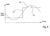
- Fig. 6 This is illustrated in Fig. 6 for said idealized half-wake situation.
- the curve 14 illustrates a desired abrupt change in pitch angle control and the curve 15 illustrates an actual corrective pitch angle control applied by the said rotor-cyclic pitch technique. Due to the difference between the two curves, an angle error 16 is introduced still resulting in a possibility of increased fatigue loads on the rotor blades.
- Fig. 7 illustrates for the present invention a preferred embodiment of the said control system for controlling the pitch angles of the wind turbine blades.
- M R [m 1 m 2 m 3 ] T on the rotor blades and the azimuth angle ⁇ is measured by the sensor means and feed to the computer means.
- M R is transformed into a coordinate system defined by the tilt, yaw and thrust equivalent direction
- T cos ⁇ cos ⁇ + 4 3 ⁇ ⁇ cos ⁇ + 2 3 ⁇ ⁇ - sin ⁇ - sin ⁇ + 4 3 ⁇ ⁇ - sin ⁇ + 2 3 ⁇ ⁇ 1 1 1
- M F is data processed by a filter (H) to M F h , deriving and processing a plurality of harmonic functions on different multiple integers of the rotor frequency ( ⁇ nom ) in order to adapt the pitch angle control system to minimize the fluctuations on measured load data in such a way, that the loads on the rotor blades are kept constant or nearly constant.
- a preferred embodiment of said data processing filter (H) is a Recursive Least Square (RLS) Estimator with exponential forgetting. This is a mathematical optimization technique that attempts to find a best fit to a set of data by attempting to minimize the sum of the squares of deviation between a set of observed data and a set of expected data.
- RLS Recursive Least Square
- the RLS processing algorithm is based on a few key-operators and can in a computer simulation be implemented after the following algorithm:
- the said RLS filter is adaptive which yields that the output of the filter changes as a response to a change on the input.
- a practical applied version of the data processing comprises computing means for digital data acquisition, harmonic analysis, RLS filter computation, data storage and D/A converting, continuously or for a predetermined period of time.
- the corrective pitch angle control signal is time shifted in relation to the measured blade loads M R .
- Q i t cos ⁇ i ⁇ ⁇ sin ⁇ i ⁇ T
- m tilt , m yaw are illustrated in fig. 8b as a function of one full rotation of the rotor.
- a i 1 ⁇ ⁇ 0 2 ⁇ ⁇ m ⁇ ⁇ cos i ⁇ ⁇ d ⁇
- the Fourier series consists of a non-alternating component, components that alternate according to the basic parameter ⁇ and a plurality of periodic functions of different integer multiples of the basic frequency.
- the weighted Fourier coefficients a i , b i determine the amplitude of each harmonic frequency in the original signal.
- the said RLS estimator data processes a truncated number of periodic functions derived by the harmonic analysis e.g. the first four multiple harmonics of the basic rotor frequency.
- the purpose of the RLS estimator is to produce an output signal that is feed to the pitch control system in order to minimize the energy in the load signal M R i.e. to minimize the fluctuating loads on the rotor blades.
- the input signals 17, 19 representing the loads moments m tilt , and m yaw of M F respectively are illustrated in figure 9 .
- the output signals m tilt h and m yaw h of M F h are represented by 18, 20 respectively.
- the said RLS filter has processed the first four multiple harmonics of the basic frequency.
- filtered signal M R h is gain adjusted ⁇ dem h and added to an overall pitch angle control signal ⁇ dem c defined by a wind turbine speed controller and the summarized control signal ⁇ dem is feed to the pitch controller that effectuates the desired actions.
- Fig. 10 illustrates a data processed pitch control signal, e.g. m l h of M R h , from the example above, corresponding to an idealized half-wake situation.
- the curve 14 illustrates a desired abrupt change in pitch angle control and the curve 22 illustrates an actual corrective pitch angle control applied by the said rotor-cyclic pitch technique. The difference between the two curves is illustrated by 21.
Landscapes
- Engineering & Computer Science (AREA)
- Life Sciences & Earth Sciences (AREA)
- Sustainable Development (AREA)
- Sustainable Energy (AREA)
- Chemical & Material Sciences (AREA)
- Combustion & Propulsion (AREA)
- Mechanical Engineering (AREA)
- General Engineering & Computer Science (AREA)
- Physics & Mathematics (AREA)
- Fluid Mechanics (AREA)
- Wind Motors (AREA)
Claims (15)
- Procédé destiné à réduire les charges de fatigue dans les éléments d'une éolienne (1) soumise à une charge asymétrique de son rotor (6), comprenant les étapes consistant à :collecter à plusieurs reprises et stocker des données de charge du rotor (6),définir une fonction de répartition des charges pour le rotor à partir desdites données stockées,dériver plusieurs fonctions périodiques de ladite fonction de répartition des charges,définir des actions pour un moyen de commande (12) d'éolienne destiné à réduire la charge de fatigue sur les éléments de l'éolienne à partir desdites plusieurs fonctions périodiques dérivées, etmettre en oeuvre lesdites actions définies dans le moyen de commande (12) de l'éolienne.
- Procédé selon la revendication 1, dans lequel lesdites plusieurs fonctions périodiques dérivées sont des fonctions sinusoïdales et/ou cosinusoïdales.
- Procédé selon l'une quelconque des revendications 1 ou 2, dans lequel les fréquences desdites plusieurs fonctions périodiques sont différents multiples entiers de la fréquence du rotor, par exemple jusqu'à 4 fois la fréquence du rotor tel que l'un quelconque du premier, deuxième, troisième et quatrième multiple de la fréquence du rotor ou une combinaison d'au moins deux desdits multiples.
- Procédé selon l'une quelconque des revendications précédentes, dans lequel au moins une composante d'amplitude et une composante de phase sont définies pour chaque fonction périodique dérivée.
- Procédé selon l'une quelconque des revendications précédentes, dans lequel lesdites plusieurs fonctions périodiques comprennent au moins une fonction de fréquence égale à la fréquence du rotor.
- Procédé selon l'une quelconque des revendications précédentes, dans lequel lesdites plusieurs fonctions périodiques comprennent au moins une fonction dont fréquence est égale à quatre fois la fréquence du rotor.
- Procédé selon l'une quelconque des revendications précédentes, dans lequel lesdites plusieurs fonctions périodiques sont dérivées par application d'une transformée de Fourier discrète à la fonction de répartition des charges.
- Procédé selon l'une quelconque des revendications précédentes, dans lequel lesdites plusieurs fonctions périodiques sont dérivées par application d'un estimateur des moindres carrés récursif à la fonction de répartition des charges.
- Système de commande (12) destiné à exécuter la méthode de réduction des charges de fatigue dans les éléments d'une éolienne (1) soumise à une charge asymétrique de son rotor selon l'une quelconque des revendications 1 à 8, ledit système de commande comprenant :- des moyens de collecte et de stockage de données pour collecter à plusieurs reprises et stocker des données de charge (MR) du rotor,- un moyen de commande d'éolienne pour commander la puissance captée par l'éolienne (1), et- un moyen de traitement de données pour traiter lesdites données de charge du rotor (6) de l'éolienne (1) collectées et produire une sortie de commande correspondante,où ledit moyen de traitement de données est adapté pour définir une fonction de répartition des charges (MF) du rotor à partir desdites données de charge stockées, en dérivant plusieurs fonctions périodiques (MF {h}) de ladite fonction de répartition des charges (MF), en définissant, sur la base desdites plusieurs fonctions périodiques (MF {h}), des actions pour ledit moyen de commande d'éolienne destiné à réduire les charges de fatigue sur les éléments de l'éolienne, et en produisant une sortie de commande correspondante destinée au moyen de commande d'éolienne.
- Système de commande selon la revendication 9, comprenant un moyen pour dériver de ladite fonction de répartition des charges plusieurs fonctions périodiques dont les fréquences correspondent à différents multiples entiers de la fréquence du rotor.
- Système de commande selon l'une quelconque des revendications 9 ou 10, comprenant des moyens transducteurs disposés pour mesurer les moments de flexion des pales, par exemple à proximité du pied d'au moins une des pales de l'éolienne, et produire une sortie correspondante destinée au moyen de collecte de données.
- Système de commande selon la revendication 11, dans lequel lesdits moyens transducteurs sont disposés pour mesurer les moments de flexion au niveau du pied de pale d'au moins deux des pales dudit rotor.
- Système de commande selon l'une quelconque des revendications 11 à 12, comprenant des moyens transducteurs disposés pour mesurer les forces exercées sur l'arbre principal de l'éolienne.
- Éolienne comprenant un système de commande selon l'une quelconque des revendications 9 à 13 destiné à réduire les charges de fatigue dans les éléments de l'éolienne soumise à une charge asymétrique du plan du rotor.
- Parc éolien comprenant au moins deux éoliennes dans lequel au moins une éolienne est commandée par un système de commande selon l'une quelconque des revendications 9 à 13 destiné à réduire les charges de fatigue dans les éléments de l'éolienne soumise à une charge asymétrique du plan du rotor.
Applications Claiming Priority (1)
| Application Number | Priority Date | Filing Date | Title |
|---|---|---|---|
| PCT/DK2006/000153 WO2007104306A1 (fr) | 2006-03-16 | 2006-03-16 | Procédé et système de commande destinés à réduire les charges de fatigue dans les éléments d'une éolienne soumise à une charge asymétrique du plan du rotor |
Publications (2)
| Publication Number | Publication Date |
|---|---|
| EP1994281A1 EP1994281A1 (fr) | 2008-11-26 |
| EP1994281B1 true EP1994281B1 (fr) | 2013-05-22 |
Family
ID=37304041
Family Applications (1)
| Application Number | Title | Priority Date | Filing Date |
|---|---|---|---|
| EP06706123.4A Revoked EP1994281B1 (fr) | 2006-03-16 | 2006-03-16 | Procédé et système de commande destinés à réduire les charges de fatigue dans les éléments d'une éolienne soumise à une charge asymétrique du plan du rotor |
Country Status (9)
| Country | Link |
|---|---|
| US (1) | US7569945B2 (fr) |
| EP (1) | EP1994281B1 (fr) |
| CN (1) | CN101400892B (fr) |
| AU (1) | AU2006339899B2 (fr) |
| BR (1) | BRPI0621442A2 (fr) |
| CA (1) | CA2645108C (fr) |
| ES (1) | ES2414093T3 (fr) |
| MX (1) | MX2008011751A (fr) |
| WO (1) | WO2007104306A1 (fr) |
Families Citing this family (66)
| Publication number | Priority date | Publication date | Assignee | Title |
|---|---|---|---|---|
| AU2004316333B2 (en) * | 2004-02-27 | 2010-09-02 | Mitsubishi Heavy Industries, Ltd. | Wind turbine generator, active damping method thereof, and windmill tower |
| ES2414093T3 (es) * | 2006-03-16 | 2013-07-18 | Vestas Wind Systems A/S | Un procedimiento y un sistema de control para la reducción de las cargas de fatiga en los componentes de una turbina eólica sometida a una carga asimétrica del plano de rotor |
| US7437264B2 (en) | 2006-06-19 | 2008-10-14 | General Electric Company | Methods and apparatus for balancing a rotor |
| DE102006054667B4 (de) | 2006-11-17 | 2011-02-17 | Windcomp Gmbh | Kollisionswarnsystem für eine Windenergieanlage |
| EP2132437B2 (fr) | 2007-03-30 | 2018-10-03 | Vestas Wind Systems A/S | Eolienne avec commande de pas |
| EP1978246A1 (fr) | 2007-04-04 | 2008-10-08 | Siemens Aktiengesellschaft | Procédé pour réduire un déséquilibre dans un rotor d'éolienne et dispositif pour réaliser le procédé |
| EP2000667B1 (fr) * | 2007-06-04 | 2011-08-10 | Siemens Aktiengesellschaft | Procédé et dispositif pour le contrôle de la réduction de charge pour un rotor d'éolienne |
| DE102007026995C5 (de) | 2007-06-07 | 2017-03-30 | Senvion Gmbh | Drehzahlbestimmung |
| WO2009033484A2 (fr) * | 2007-09-13 | 2009-03-19 | Vestas Wind Systems A/S | Procédé de commande d'une éolienne, éolienne et utilisation du procédé |
| CN101874158A (zh) * | 2007-10-29 | 2010-10-27 | 维斯塔斯风力系统有限公司 | 风轮机叶片以及用于控制叶片上的载荷的方法 |
| WO2009068036A2 (fr) * | 2007-11-30 | 2009-06-04 | Vestas Wind Systems A/S | Éolienne, procédé pour commander une éolienne et utilisation de celle-ci |
| CN101878365B (zh) | 2007-11-30 | 2012-06-27 | 维斯塔斯风力系统有限公司 | 风力涡轮机、控制风力涡轮机的方法及其用途 |
| DE102007063082B4 (de) * | 2007-12-21 | 2010-12-09 | Repower Systems Ag | Verfahren zum Betreiben einer Windenergieanlage |
| US8805595B2 (en) * | 2008-01-17 | 2014-08-12 | General Electric Company | Wind turbine arranged for independent operation of its components and related method and computer program |
| DE102008009740A1 (de) | 2008-02-18 | 2009-08-20 | Imo Holding Gmbh | Windkraftanlage sowie Verfahren zum Betrieb derselben |
| CN101983325B (zh) | 2008-03-31 | 2013-04-24 | 维斯塔斯风力系统集团公司 | 用于风力涡轮机的光透射应变传感器 |
| DK2110551T4 (da) | 2008-04-15 | 2019-05-13 | Siemens Ag | Fremgangsmåde og indretning til prognose-baseret vindmøllestyring |
| EP2112374B2 (fr) | 2008-04-21 | 2018-10-17 | Siemens Aktiengesellschaft | Système de détection de fissures |
| DE102008031816A1 (de) * | 2008-06-25 | 2009-12-31 | Lange, Wilhelm, Dr. | Verfahren zum Betreiben einer Windkraftanlage |
| GB2461532A (en) | 2008-07-01 | 2010-01-06 | Vestas Wind Sys As | Sensor system and method for detecting deformation in a wind turbine component |
| GB2461566A (en) | 2008-07-03 | 2010-01-06 | Vestas Wind Sys As | Embedded fibre optic sensor for mounting on wind turbine components and method of producing the same. |
| JP5244502B2 (ja) | 2008-08-25 | 2013-07-24 | 三菱重工業株式会社 | 風車の運転制限調整装置及び方法並びにプログラム |
| GB2463696A (en) | 2008-09-22 | 2010-03-24 | Vestas Wind Sys As | Edge-wise bending insensitive strain sensor system |
| US20100092292A1 (en) * | 2008-10-10 | 2010-04-15 | Jacob Johannes Nies | Apparatus and method for continuous pitching of a wind turbine |
| US7988414B2 (en) * | 2008-10-20 | 2011-08-02 | General Electric Company | Method and system for operating a wind turbine generator |
| GB2466433B (en) | 2008-12-16 | 2011-05-25 | Vestas Wind Sys As | Turbulence sensor and blade condition sensor system |
| WO2010086688A1 (fr) | 2009-01-28 | 2010-08-05 | Clipper Windpower, Inc. | Atténuation de charge dans une éolienne |
| WO2010098813A1 (fr) * | 2009-02-28 | 2010-09-02 | Ener2 Llc | Dispositif à énergie éolienne |
| SE534957C2 (sv) * | 2009-05-20 | 2012-02-28 | Ge Wind Energy Norway As | Metod för att bestämma ett balanserat läge hos en vindturbin |
| US8222757B2 (en) | 2009-06-05 | 2012-07-17 | General Electric Company | Load identification system and method of assembling the same |
| US7763989B2 (en) * | 2009-07-07 | 2010-07-27 | General Electric Company | Method and apparatus for controlling the tip speed of a blade of a wind turbine |
| GB2472437A (en) | 2009-08-06 | 2011-02-09 | Vestas Wind Sys As | Wind turbine rotor blade control based on detecting turbulence |
| US7772713B2 (en) * | 2009-09-30 | 2010-08-10 | General Electric Company | Method and system for controlling a wind turbine |
| WO2011057633A2 (fr) * | 2009-11-11 | 2011-05-19 | Vestas Wind Systems A/S | Commande améliorée de moyen de régulation de levage de pales de turbine éolienne |
| US20110229300A1 (en) * | 2010-03-16 | 2011-09-22 | Stichting Energieonderzoek Centrum Nederland | Apparatus and method for individual pitch control in wind turbines |
| US8035241B2 (en) * | 2010-07-09 | 2011-10-11 | General Electric Company | Wind turbine, control system, and method for optimizing wind turbine power production |
| US20110182730A1 (en) * | 2010-07-27 | 2011-07-28 | Vestas Wind Systems A/S | Wind turbine blade with damping element for edgewise vibrations |
| WO2012083958A2 (fr) | 2010-12-21 | 2012-06-28 | Vestas Wind Systems A/S | Procédé de commande d'une éolienne |
| GB2484156A (en) * | 2010-12-24 | 2012-04-04 | Moog Insensys Ltd | Method of reducing stress load in a wind turbine rotor |
| EP2497946A1 (fr) * | 2011-03-09 | 2012-09-12 | Siemens Aktiengesellschaft | Procédé et agencement permettant de détecter un désalignement d'angle de calage de pale du rotor d'éolienne |
| JP2013011233A (ja) | 2011-06-29 | 2013-01-17 | Mitsubishi Heavy Ind Ltd | 風力発電装置保守装置および風力発電装置保守方法 |
| WO2013037374A1 (fr) * | 2011-09-13 | 2013-03-21 | Vestas Wind Systems A/S | Procédé permettant d'améliorer la performance de la puissance d'un parc éolien à réseau de grande taille par la manipulation active du sillage pour réduire les effets d'ombre |
| DK201170539A (en) * | 2011-09-30 | 2013-03-31 | Vestas Wind Sys As | Control of wind turbines |
| WO2013097860A1 (fr) * | 2011-12-30 | 2013-07-04 | Vestas Wind Systems A/S | Estimation et controle de la charge supportee par une structure |
| JP5626256B2 (ja) * | 2012-04-12 | 2014-11-19 | 株式会社安川電機 | 発電装置 |
| JP2013221404A (ja) * | 2012-04-12 | 2013-10-28 | Yaskawa Electric Corp | 発電装置および発電システム |
| US20130302161A1 (en) * | 2012-05-08 | 2013-11-14 | Arne Koerber | Controller of wind turbine and wind turbine |
| US9835137B2 (en) * | 2012-06-08 | 2017-12-05 | Vestas Wind Systems A/S | Compensation for asymmetric load moment experienced by wind turbine rotor |
| ES2442452B1 (es) * | 2012-07-11 | 2014-12-22 | Acciona Windpower, S.A. | Método de control de aerogenerador |
| US9261077B2 (en) * | 2013-03-19 | 2016-02-16 | General Electric Company | System and method for real-time load control of a wind turbine |
| US9593668B2 (en) | 2013-09-10 | 2017-03-14 | General Electric Company | Methods and systems for reducing amplitude modulation in wind turbines |
| JP5984791B2 (ja) * | 2013-12-20 | 2016-09-06 | 三菱重工業株式会社 | 風力発電装置のモニタリングシステム及びモニタリング方法 |
| ES2937262T3 (es) * | 2014-06-20 | 2023-03-27 | Mita Teknik As | Sistema de control dinámico de inclinación |
| EP2995813B1 (fr) * | 2014-09-12 | 2017-08-09 | LM WP Patent Holding A/S | Systèmes et procédés permettant de déterminer la déviation d'un arbre d'éolienne |
| CN107429663A (zh) * | 2015-03-27 | 2017-12-01 | 西门子公司 | 风力涡轮机的控制 |
| ES2784942T3 (es) | 2016-02-12 | 2020-10-02 | Vestas Wind Sys As | Mejoras referentes al control del desgaste de cojinetes |
| CN107676223B (zh) * | 2016-08-02 | 2018-12-21 | 北京金风科创风电设备有限公司 | 风力发电机组变桨控制方法及装置 |
| US10544700B2 (en) * | 2016-08-31 | 2020-01-28 | General Electric Technology Gmbh | Advanced startup counter module for a valve and actuator monitoring system |
| WO2018059641A1 (fr) * | 2016-09-29 | 2018-04-05 | Vestas Wind Systems A/S | Procédé de commande pour éolienne |
| US10781792B2 (en) | 2017-05-18 | 2020-09-22 | General Electric Company | System and method for controlling a pitch angle of a wind turbine rotor blade |
| ES2716774A1 (es) * | 2017-12-14 | 2019-06-14 | Siemens Gamesa Renewable Energy Innovation & Technology SL | Método de control de un aerogenerador y un aerogenerador que comprende unos medios de control configurados para llevar a cabo el método de control |
| ES2942017T3 (es) * | 2018-01-09 | 2023-05-29 | Vestas Wind Sys As | Un método para controlar un parque de energía eólica teniendo en cuenta efectos de estela |
| US11635062B2 (en) | 2018-11-07 | 2023-04-25 | General Electric Renovables Espana, S.L. | Wind turbine and method to determine modal characteristics of the wind turbine in a continuous manner |
| CN112555102B (zh) * | 2019-09-26 | 2022-07-19 | 北京金风科创风电设备有限公司 | 识别叶片桨距角偏差及控制风力发电机组的方法及装置 |
| CN113494418A (zh) | 2020-04-08 | 2021-10-12 | 通用电气可再生能源西班牙有限公司 | 用于减轻作用于风力涡轮的转子叶片的负载的系统和方法 |
| WO2021230817A1 (fr) * | 2020-05-12 | 2021-11-18 | Singapore University Of Technology And Design | Dispositif aérien autorotatif, procédé de formation du dispositif aérien autorotatif et système aérien autorotatif |
Family Cites Families (30)
| Publication number | Priority date | Publication date | Assignee | Title |
|---|---|---|---|---|
| US4161658A (en) * | 1978-06-15 | 1979-07-17 | United Technologies Corporation | Wind turbine generator having integrator tracking |
| US4348155A (en) * | 1980-03-17 | 1982-09-07 | United Technologies Corporation | Wind turbine blade pitch control system |
| US4435647A (en) * | 1982-04-02 | 1984-03-06 | United Technologies Corporation | Predicted motion wind turbine tower damping |
| US4584486A (en) * | 1984-04-09 | 1986-04-22 | The Boeing Company | Blade pitch control of a wind turbine |
| US5584655A (en) * | 1994-12-21 | 1996-12-17 | The Wind Turbine Company | Rotor device and control for wind turbine |
| US5660527A (en) * | 1995-10-05 | 1997-08-26 | The Wind Turbine Company | Wind turbine rotor blade root end |
| EP0995904A3 (fr) * | 1998-10-20 | 2002-02-06 | Tacke Windenergie GmbH | Eolienne |
| JP3978186B2 (ja) * | 2001-12-28 | 2007-09-19 | 三菱重工業株式会社 | アップウィンド型風車及びその運転方法 |
| US7071578B1 (en) * | 2002-01-10 | 2006-07-04 | Mitsubishi Heavy Industries, Ltd. | Wind turbine provided with a controller for adjusting active annular plane area and the operating method thereof |
| US6888262B2 (en) * | 2003-02-03 | 2005-05-03 | General Electric Company | Method and apparatus for wind turbine rotor load control |
| WO2004074681A1 (fr) * | 2003-02-18 | 2004-09-02 | Forskningscenter Risø | Methode de commande de la charge aerodynamique d'une eolienne en fonction de la mesure de l'ecoulement local au niveau des pales |
| US6940185B2 (en) * | 2003-04-10 | 2005-09-06 | Advantek Llc | Advanced aerodynamic control system for a high output wind turbine |
| NO20041208L (no) * | 2004-03-22 | 2005-09-23 | Sway As | Fremgangsmate for reduskjon av aksialkraftvariasjoner for rotor samt retningskontroll for vindkraft med aktiv pitchregulering |
| US7095129B2 (en) * | 2004-06-30 | 2006-08-22 | General Electric Company | Methods and apparatus for rotor load control in wind turbines |
| US7175389B2 (en) * | 2004-06-30 | 2007-02-13 | General Electric Company | Methods and apparatus for reducing peak wind turbine loads |
| US7121795B2 (en) * | 2004-06-30 | 2006-10-17 | General Electric Company | Method and apparatus for reducing rotor blade deflections, loads, and/or peak rotational speed |
| US7118339B2 (en) * | 2004-06-30 | 2006-10-10 | General Electric Company | Methods and apparatus for reduction of asymmetric rotor loads in wind turbines |
| US7153090B2 (en) * | 2004-12-17 | 2006-12-26 | General Electric Company | System and method for passive load attenuation in a wind turbine |
| US7822560B2 (en) * | 2004-12-23 | 2010-10-26 | General Electric Company | Methods and apparatuses for wind turbine fatigue load measurement and assessment |
| US7387491B2 (en) * | 2004-12-23 | 2008-06-17 | General Electric Company | Active flow modifications on wind turbine blades |
| DE102005029000B4 (de) * | 2005-06-21 | 2007-04-12 | Repower Systems Ag | Verfahren und System zur Regelung der Drehzahl eines Rotors einer Windenergieanlage |
| US7476985B2 (en) * | 2005-07-22 | 2009-01-13 | Gamesa Innovation & Technology, S.L. | Method of operating a wind turbine |
| US7802968B2 (en) * | 2005-07-29 | 2010-09-28 | General Electric Company | Methods and apparatus for reducing load in a rotor blade |
| US7342323B2 (en) * | 2005-09-30 | 2008-03-11 | General Electric Company | System and method for upwind speed based control of a wind turbine |
| CA2625070A1 (fr) * | 2005-10-17 | 2007-04-26 | Vestas Wind Systems A/S | Pale d'aerogenerateur a profil aerodynamique variable |
| NO325856B1 (no) * | 2005-11-01 | 2008-08-04 | Hywind As | Fremgangsmåte for demping av ustabile frie stivlegeme egensvingninger ved en flytende vindturbininstallasjon |
| US7276807B2 (en) * | 2006-01-19 | 2007-10-02 | General Electric Company | Wind turbine dump load system and method |
| ES2414093T3 (es) * | 2006-03-16 | 2013-07-18 | Vestas Wind Systems A/S | Un procedimiento y un sistema de control para la reducción de las cargas de fatiga en los componentes de una turbina eólica sometida a una carga asimétrica del plano de rotor |
| WO2007114698A2 (fr) * | 2006-04-02 | 2007-10-11 | Gustave Paul Corten | Éolienne à pales éffilées |
| EP2017468A1 (fr) * | 2007-07-20 | 2009-01-21 | Siemens Aktiengesellschaft | Procédé pour le contrôle de lacet d'éolienne |
-
2006
- 2006-03-16 ES ES06706123T patent/ES2414093T3/es active Active
- 2006-03-16 BR BRPI0621442-8A patent/BRPI0621442A2/pt not_active IP Right Cessation
- 2006-03-16 AU AU2006339899A patent/AU2006339899B2/en not_active Ceased
- 2006-03-16 MX MX2008011751A patent/MX2008011751A/es active IP Right Grant
- 2006-03-16 EP EP06706123.4A patent/EP1994281B1/fr not_active Revoked
- 2006-03-16 CN CN2006800538643A patent/CN101400892B/zh not_active Expired - Fee Related
- 2006-03-16 WO PCT/DK2006/000153 patent/WO2007104306A1/fr active Application Filing
- 2006-03-16 CA CA2645108A patent/CA2645108C/fr not_active Expired - Fee Related
-
2008
- 2008-09-15 US US12/210,730 patent/US7569945B2/en not_active Expired - Fee Related
Also Published As
| Publication number | Publication date |
|---|---|
| AU2006339899B2 (en) | 2010-04-01 |
| BRPI0621442A2 (pt) | 2011-12-13 |
| CN101400892A (zh) | 2009-04-01 |
| ES2414093T3 (es) | 2013-07-18 |
| CA2645108C (fr) | 2014-03-11 |
| CN101400892B (zh) | 2013-04-17 |
| EP1994281A1 (fr) | 2008-11-26 |
| MX2008011751A (es) | 2008-11-12 |
| US7569945B2 (en) | 2009-08-04 |
| CA2645108A1 (fr) | 2007-09-20 |
| AU2006339899A1 (en) | 2007-09-20 |
| US20090021015A1 (en) | 2009-01-22 |
| WO2007104306A1 (fr) | 2007-09-20 |
Similar Documents
| Publication | Publication Date | Title |
|---|---|---|
| EP1994281B1 (fr) | Procédé et système de commande destinés à réduire les charges de fatigue dans les éléments d'une éolienne soumise à une charge asymétrique du plan du rotor | |
| EP2132437B1 (fr) | Eolienne avec commande de pas | |
| Bossanyi et al. | Validation of individual pitch control by field tests on two-and three-bladed wind turbines | |
| EP3613982B1 (fr) | Procédé de commande de fonctionnement d'une éolienne | |
| EP3274584B1 (fr) | Commande d'un système d'éolienne à rotors multiples utilisant un dispositif de commande central pour calculer des objectifs de commande locaux | |
| US10683844B2 (en) | Control of a wind turbine taking fatigue measure into account | |
| EP3821125B1 (fr) | Procédé et système permettant de commander une éolienne afin de réduire les vibrations de la nacelle | |
| EP2859225B1 (fr) | Procédé de fonctionnement d'une éolienne et système approprié | |
| US10107259B2 (en) | Control method for a wind turbine, and wind turbine | |
| EP2481921B1 (fr) | Procédés améliorés de contrôle d'éolienne et systèmes | |
| EP2249030A2 (fr) | Éolienne | |
| US9719494B2 (en) | Methods of operating a wind turbine, wind turbines and wind parks | |
| EP3682110B1 (fr) | Contrôle à calage variable de pale individuelle pour éoliennes | |
| EP3705716B9 (fr) | Limites de poussée pour éoliennes | |
| EP2881581A1 (fr) | Système et procédé de commande d'éolienne | |
| EP4115079B1 (fr) | Procédé et dispositif de commande d'un parc éolien | |
| Nam | Control system design | |
| EP3867520B1 (fr) | Modification de la stratégie de commande pour la commande d'une éolienne en utilisant la probabilité de charge et la limite de charge nominale | |
| CN113825903A (zh) | 用于基于变化元件来控制风力涡轮机的装置和方法 | |
| EP4050207A1 (fr) | Procédé de configuration d'un organe de commande de pas d'éolienne | |
| Merz et al. | Supervisory Wind Farm Control |
Legal Events
| Date | Code | Title | Description |
|---|---|---|---|
| PUAI | Public reference made under article 153(3) epc to a published international application that has entered the european phase |
Free format text: ORIGINAL CODE: 0009012 |
|
| 17P | Request for examination filed |
Effective date: 20080915 |
|
| AK | Designated contracting states |
Kind code of ref document: A1 Designated state(s): AT BE BG CH CY CZ DE DK EE ES FI FR GB GR HU IE IS IT LI LT LU LV MC NL PL PT RO SE SI SK TR |
|
| RAP1 | Party data changed (applicant data changed or rights of an application transferred) |
Owner name: VESTAS WIND SYSTEMS A/S |
|
| DAX | Request for extension of the european patent (deleted) | ||
| GRAP | Despatch of communication of intention to grant a patent |
Free format text: ORIGINAL CODE: EPIDOSNIGR1 |
|
| GRAS | Grant fee paid |
Free format text: ORIGINAL CODE: EPIDOSNIGR3 |
|
| GRAA | (expected) grant |
Free format text: ORIGINAL CODE: 0009210 |
|
| STAA | Information on the status of an ep patent application or granted ep patent |
Free format text: STATUS: THE PATENT HAS BEEN GRANTED |
|
| AK | Designated contracting states |
Kind code of ref document: B1 Designated state(s): AT BE BG CH CY CZ DE DK EE ES FI FR GB GR HU IE IS IT LI LT LU LV MC NL PL PT RO SE SI SK TR |
|
| REG | Reference to a national code |
Ref country code: GB Ref legal event code: FG4D |
|
| REG | Reference to a national code |
Ref country code: CH Ref legal event code: EP |
|
| REG | Reference to a national code |
Ref country code: AT Ref legal event code: REF Ref document number: 613373 Country of ref document: AT Kind code of ref document: T Effective date: 20130615 |
|
| REG | Reference to a national code |
Ref country code: IE Ref legal event code: FG4D |
|
| REG | Reference to a national code |
Ref country code: ES Ref legal event code: FG2A Ref document number: 2414093 Country of ref document: ES Kind code of ref document: T3 Effective date: 20130718 Ref country code: DE Ref legal event code: R096 Ref document number: 602006036396 Country of ref document: DE Effective date: 20130718 |
|
| REG | Reference to a national code |
Ref country code: AT Ref legal event code: MK05 Ref document number: 613373 Country of ref document: AT Kind code of ref document: T Effective date: 20130522 |
|
| REG | Reference to a national code |
Ref country code: LT Ref legal event code: MG4D |
|
| PG25 | Lapsed in a contracting state [announced via postgrant information from national office to epo] |
Ref country code: FI Free format text: LAPSE BECAUSE OF FAILURE TO SUBMIT A TRANSLATION OF THE DESCRIPTION OR TO PAY THE FEE WITHIN THE PRESCRIBED TIME-LIMIT Effective date: 20130522 Ref country code: PT Free format text: LAPSE BECAUSE OF FAILURE TO SUBMIT A TRANSLATION OF THE DESCRIPTION OR TO PAY THE FEE WITHIN THE PRESCRIBED TIME-LIMIT Effective date: 20130923 Ref country code: AT Free format text: LAPSE BECAUSE OF FAILURE TO SUBMIT A TRANSLATION OF THE DESCRIPTION OR TO PAY THE FEE WITHIN THE PRESCRIBED TIME-LIMIT Effective date: 20130522 Ref country code: SI Free format text: LAPSE BECAUSE OF FAILURE TO SUBMIT A TRANSLATION OF THE DESCRIPTION OR TO PAY THE FEE WITHIN THE PRESCRIBED TIME-LIMIT Effective date: 20130522 Ref country code: IS Free format text: LAPSE BECAUSE OF FAILURE TO SUBMIT A TRANSLATION OF THE DESCRIPTION OR TO PAY THE FEE WITHIN THE PRESCRIBED TIME-LIMIT Effective date: 20130922 Ref country code: GR Free format text: LAPSE BECAUSE OF FAILURE TO SUBMIT A TRANSLATION OF THE DESCRIPTION OR TO PAY THE FEE WITHIN THE PRESCRIBED TIME-LIMIT Effective date: 20130823 Ref country code: LT Free format text: LAPSE BECAUSE OF FAILURE TO SUBMIT A TRANSLATION OF THE DESCRIPTION OR TO PAY THE FEE WITHIN THE PRESCRIBED TIME-LIMIT Effective date: 20130522 Ref country code: SE Free format text: LAPSE BECAUSE OF FAILURE TO SUBMIT A TRANSLATION OF THE DESCRIPTION OR TO PAY THE FEE WITHIN THE PRESCRIBED TIME-LIMIT Effective date: 20130522 |
|
| REG | Reference to a national code |
Ref country code: NL Ref legal event code: VDEP Effective date: 20130522 |
|
| PG25 | Lapsed in a contracting state [announced via postgrant information from national office to epo] |
Ref country code: PL Free format text: LAPSE BECAUSE OF FAILURE TO SUBMIT A TRANSLATION OF THE DESCRIPTION OR TO PAY THE FEE WITHIN THE PRESCRIBED TIME-LIMIT Effective date: 20130522 Ref country code: BG Free format text: LAPSE BECAUSE OF FAILURE TO SUBMIT A TRANSLATION OF THE DESCRIPTION OR TO PAY THE FEE WITHIN THE PRESCRIBED TIME-LIMIT Effective date: 20130822 |
|
| PLBI | Opposition filed |
Free format text: ORIGINAL CODE: 0009260 |
|
| PG25 | Lapsed in a contracting state [announced via postgrant information from national office to epo] |
Ref country code: LV Free format text: LAPSE BECAUSE OF FAILURE TO SUBMIT A TRANSLATION OF THE DESCRIPTION OR TO PAY THE FEE WITHIN THE PRESCRIBED TIME-LIMIT Effective date: 20130522 |
|
| 26 | Opposition filed |
Opponent name: SIEMENS AKTIENGESELLSCHAFT Effective date: 20131216 |
|
| PG25 | Lapsed in a contracting state [announced via postgrant information from national office to epo] |
Ref country code: SK Free format text: LAPSE BECAUSE OF FAILURE TO SUBMIT A TRANSLATION OF THE DESCRIPTION OR TO PAY THE FEE WITHIN THE PRESCRIBED TIME-LIMIT Effective date: 20130522 Ref country code: DK Free format text: LAPSE BECAUSE OF FAILURE TO SUBMIT A TRANSLATION OF THE DESCRIPTION OR TO PAY THE FEE WITHIN THE PRESCRIBED TIME-LIMIT Effective date: 20130522 Ref country code: CZ Free format text: LAPSE BECAUSE OF FAILURE TO SUBMIT A TRANSLATION OF THE DESCRIPTION OR TO PAY THE FEE WITHIN THE PRESCRIBED TIME-LIMIT Effective date: 20130522 Ref country code: BE Free format text: LAPSE BECAUSE OF FAILURE TO SUBMIT A TRANSLATION OF THE DESCRIPTION OR TO PAY THE FEE WITHIN THE PRESCRIBED TIME-LIMIT Effective date: 20130522 Ref country code: EE Free format text: LAPSE BECAUSE OF FAILURE TO SUBMIT A TRANSLATION OF THE DESCRIPTION OR TO PAY THE FEE WITHIN THE PRESCRIBED TIME-LIMIT Effective date: 20130522 |
|
| REG | Reference to a national code |
Ref country code: DE Ref legal event code: R026 Ref document number: 602006036396 Country of ref document: DE Effective date: 20131216 |
|
| PG25 | Lapsed in a contracting state [announced via postgrant information from national office to epo] |
Ref country code: NL Free format text: LAPSE BECAUSE OF FAILURE TO SUBMIT A TRANSLATION OF THE DESCRIPTION OR TO PAY THE FEE WITHIN THE PRESCRIBED TIME-LIMIT Effective date: 20130522 Ref country code: IT Free format text: LAPSE BECAUSE OF FAILURE TO SUBMIT A TRANSLATION OF THE DESCRIPTION OR TO PAY THE FEE WITHIN THE PRESCRIBED TIME-LIMIT Effective date: 20130522 Ref country code: RO Free format text: LAPSE BECAUSE OF FAILURE TO SUBMIT A TRANSLATION OF THE DESCRIPTION OR TO PAY THE FEE WITHIN THE PRESCRIBED TIME-LIMIT Effective date: 20130522 |
|
| PLBI | Opposition filed |
Free format text: ORIGINAL CODE: 0009260 |
|
| PLAX | Notice of opposition and request to file observation + time limit sent |
Free format text: ORIGINAL CODE: EPIDOSNOBS2 |
|
| 26 | Opposition filed |
Opponent name: ENERCON GMBH Effective date: 20140220 |
|
| PLAF | Information modified related to communication of a notice of opposition and request to file observations + time limit |
Free format text: ORIGINAL CODE: EPIDOSCOBS2 |
|
| PLBB | Reply of patent proprietor to notice(s) of opposition received |
Free format text: ORIGINAL CODE: EPIDOSNOBS3 |
|
| PG25 | Lapsed in a contracting state [announced via postgrant information from national office to epo] |
Ref country code: LU Free format text: LAPSE BECAUSE OF FAILURE TO SUBMIT A TRANSLATION OF THE DESCRIPTION OR TO PAY THE FEE WITHIN THE PRESCRIBED TIME-LIMIT Effective date: 20140316 |
|
| REG | Reference to a national code |
Ref country code: CH Ref legal event code: PL |
|
| REG | Reference to a national code |
Ref country code: IE Ref legal event code: MM4A |
|
| PG25 | Lapsed in a contracting state [announced via postgrant information from national office to epo] |
Ref country code: IE Free format text: LAPSE BECAUSE OF NON-PAYMENT OF DUE FEES Effective date: 20140316 Ref country code: CH Free format text: LAPSE BECAUSE OF NON-PAYMENT OF DUE FEES Effective date: 20140331 Ref country code: LI Free format text: LAPSE BECAUSE OF NON-PAYMENT OF DUE FEES Effective date: 20140331 |
|
| RAP2 | Party data changed (patent owner data changed or rights of a patent transferred) |
Owner name: VESTAS WIND SYSTEMS A/S |
|
| REG | Reference to a national code |
Ref country code: FR Ref legal event code: PLFP Year of fee payment: 11 |
|
| PG25 | Lapsed in a contracting state [announced via postgrant information from national office to epo] |
Ref country code: MC Free format text: LAPSE BECAUSE OF FAILURE TO SUBMIT A TRANSLATION OF THE DESCRIPTION OR TO PAY THE FEE WITHIN THE PRESCRIBED TIME-LIMIT Effective date: 20130522 |
|
| PG25 | Lapsed in a contracting state [announced via postgrant information from national office to epo] |
Ref country code: CY Free format text: LAPSE BECAUSE OF FAILURE TO SUBMIT A TRANSLATION OF THE DESCRIPTION OR TO PAY THE FEE WITHIN THE PRESCRIBED TIME-LIMIT Effective date: 20130522 |
|
| PG25 | Lapsed in a contracting state [announced via postgrant information from national office to epo] |
Ref country code: HU Free format text: LAPSE BECAUSE OF FAILURE TO SUBMIT A TRANSLATION OF THE DESCRIPTION OR TO PAY THE FEE WITHIN THE PRESCRIBED TIME-LIMIT; INVALID AB INITIO Effective date: 20060316 Ref country code: TR Free format text: LAPSE BECAUSE OF FAILURE TO SUBMIT A TRANSLATION OF THE DESCRIPTION OR TO PAY THE FEE WITHIN THE PRESCRIBED TIME-LIMIT Effective date: 20130522 |
|
| PLBP | Opposition withdrawn |
Free format text: ORIGINAL CODE: 0009264 |
|
| REG | Reference to a national code |
Ref country code: FR Ref legal event code: PLFP Year of fee payment: 12 |
|
| PLCK | Communication despatched that opposition was rejected |
Free format text: ORIGINAL CODE: EPIDOSNREJ1 |
|
| STAA | Information on the status of an ep patent application or granted ep patent |
Free format text: STATUS: THE PATENT HAS BEEN GRANTED |
|
| APBM | Appeal reference recorded |
Free format text: ORIGINAL CODE: EPIDOSNREFNO |
|
| APBP | Date of receipt of notice of appeal recorded |
Free format text: ORIGINAL CODE: EPIDOSNNOA2O |
|
| APAH | Appeal reference modified |
Free format text: ORIGINAL CODE: EPIDOSCREFNO |
|
| PLAB | Opposition data, opponent's data or that of the opponent's representative modified |
Free format text: ORIGINAL CODE: 0009299OPPO |
|
| APBQ | Date of receipt of statement of grounds of appeal recorded |
Free format text: ORIGINAL CODE: EPIDOSNNOA3O |
|
| R26 | Opposition filed (corrected) |
Opponent name: SIEMENS AKTIENGESELLSCHAFT Effective date: 20131216 |
|
| REG | Reference to a national code |
Ref country code: FR Ref legal event code: PLFP Year of fee payment: 13 |
|
| PGFP | Annual fee paid to national office [announced via postgrant information from national office to epo] |
Ref country code: GB Payment date: 20200327 Year of fee payment: 15 |
|
| PGFP | Annual fee paid to national office [announced via postgrant information from national office to epo] |
Ref country code: FR Payment date: 20200326 Year of fee payment: 15 |
|
| PGFP | Annual fee paid to national office [announced via postgrant information from national office to epo] |
Ref country code: ES Payment date: 20200427 Year of fee payment: 15 Ref country code: DE Payment date: 20200528 Year of fee payment: 15 |
|
| REG | Reference to a national code |
Ref country code: DE Ref legal event code: R064 Ref document number: 602006036396 Country of ref document: DE Ref country code: DE Ref legal event code: R103 Ref document number: 602006036396 Country of ref document: DE |
|
| APBU | Appeal procedure closed |
Free format text: ORIGINAL CODE: EPIDOSNNOA9O |
|
| RDAF | Communication despatched that patent is revoked |
Free format text: ORIGINAL CODE: EPIDOSNREV1 |
|
| STAA | Information on the status of an ep patent application or granted ep patent |
Free format text: STATUS: PATENT REVOKED |
|
| RDAG | Patent revoked |
Free format text: ORIGINAL CODE: 0009271 |
|
| STAA | Information on the status of an ep patent application or granted ep patent |
Free format text: STATUS: PATENT REVOKED |
|
| 27W | Patent revoked |
Effective date: 20201007 |
|
| GBPR | Gb: patent revoked under art. 102 of the ep convention designating the uk as contracting state |
Effective date: 20201007 |
|
| REG | Reference to a national code |
Ref country code: FI Ref legal event code: MGE |