EP3613982B1 - Procédé de commande de fonctionnement d'une éolienne - Google Patents
Procédé de commande de fonctionnement d'une éolienne Download PDFInfo
- Publication number
- EP3613982B1 EP3613982B1 EP19192617.9A EP19192617A EP3613982B1 EP 3613982 B1 EP3613982 B1 EP 3613982B1 EP 19192617 A EP19192617 A EP 19192617A EP 3613982 B1 EP3613982 B1 EP 3613982B1
- Authority
- EP
- European Patent Office
- Prior art keywords
- wind turbine
- wind
- power
- pitch
- data
- Prior art date
- Legal status (The legal status is an assumption and is not a legal conclusion. Google has not performed a legal analysis and makes no representation as to the accuracy of the status listed.)
- Active
Links
- 238000000034 method Methods 0.000 title claims description 44
- 238000010801 machine learning Methods 0.000 claims description 26
- 238000012549 training Methods 0.000 claims description 22
- 238000004422 calculation algorithm Methods 0.000 claims description 8
- 238000007637 random forest analysis Methods 0.000 claims description 7
- 230000008569 process Effects 0.000 claims description 6
- 238000012706 support-vector machine Methods 0.000 claims description 2
- 238000005259 measurement Methods 0.000 description 23
- 238000010248 power generation Methods 0.000 description 15
- 230000006870 function Effects 0.000 description 13
- 230000001276 controlling effect Effects 0.000 description 10
- 230000007613 environmental effect Effects 0.000 description 10
- 238000004891 communication Methods 0.000 description 8
- 238000004519 manufacturing process Methods 0.000 description 8
- 230000007246 mechanism Effects 0.000 description 8
- 238000003860 storage Methods 0.000 description 7
- 230000008859 change Effects 0.000 description 6
- 238000012546 transfer Methods 0.000 description 6
- 230000033228 biological regulation Effects 0.000 description 5
- 230000001965 increasing effect Effects 0.000 description 5
- 230000008878 coupling Effects 0.000 description 4
- 238000010168 coupling process Methods 0.000 description 4
- 238000005859 coupling reaction Methods 0.000 description 4
- 238000010586 diagram Methods 0.000 description 4
- 230000000694 effects Effects 0.000 description 4
- 238000012544 monitoring process Methods 0.000 description 4
- 238000012545 processing Methods 0.000 description 4
- 230000001105 regulatory effect Effects 0.000 description 3
- 238000013528 artificial neural network Methods 0.000 description 2
- 238000003066 decision tree Methods 0.000 description 2
- 238000009826 distribution Methods 0.000 description 2
- 230000002708 enhancing effect Effects 0.000 description 2
- 238000012417 linear regression Methods 0.000 description 2
- 238000005457 optimization Methods 0.000 description 2
- 230000002093 peripheral effect Effects 0.000 description 2
- 230000001681 protective effect Effects 0.000 description 2
- 238000013024 troubleshooting Methods 0.000 description 2
- 229910000831 Steel Inorganic materials 0.000 description 1
- 238000004458 analytical method Methods 0.000 description 1
- 238000005452 bending Methods 0.000 description 1
- 230000005540 biological transmission Effects 0.000 description 1
- 238000004590 computer program Methods 0.000 description 1
- 238000011109 contamination Methods 0.000 description 1
- 238000011217 control strategy Methods 0.000 description 1
- 230000007423 decrease Effects 0.000 description 1
- SDIXRDNYIMOKSG-UHFFFAOYSA-L disodium methyl arsenate Chemical compound [Na+].[Na+].C[As]([O-])([O-])=O SDIXRDNYIMOKSG-UHFFFAOYSA-L 0.000 description 1
- 230000009977 dual effect Effects 0.000 description 1
- 238000005516 engineering process Methods 0.000 description 1
- 230000003628 erosive effect Effects 0.000 description 1
- 230000007774 longterm Effects 0.000 description 1
- 238000012423 maintenance Methods 0.000 description 1
- 230000003287 optical effect Effects 0.000 description 1
- 230000001902 propagating effect Effects 0.000 description 1
- 238000012887 quadratic function Methods 0.000 description 1
- 230000002829 reductive effect Effects 0.000 description 1
- 230000004044 response Effects 0.000 description 1
- 230000001932 seasonal effect Effects 0.000 description 1
- 230000003068 static effect Effects 0.000 description 1
- 239000010959 steel Substances 0.000 description 1
- 238000013106 supervised machine learning method Methods 0.000 description 1
- 230000036962 time dependent Effects 0.000 description 1
Images


Classifications
-
- F—MECHANICAL ENGINEERING; LIGHTING; HEATING; WEAPONS; BLASTING
- F03—MACHINES OR ENGINES FOR LIQUIDS; WIND, SPRING, OR WEIGHT MOTORS; PRODUCING MECHANICAL POWER OR A REACTIVE PROPULSIVE THRUST, NOT OTHERWISE PROVIDED FOR
- F03D—WIND MOTORS
- F03D7/00—Controlling wind motors
- F03D7/02—Controlling wind motors the wind motors having rotation axis substantially parallel to the air flow entering the rotor
- F03D7/04—Automatic control; Regulation
- F03D7/042—Automatic control; Regulation by means of an electrical or electronic controller
- F03D7/043—Automatic control; Regulation by means of an electrical or electronic controller characterised by the type of control logic
- F03D7/046—Automatic control; Regulation by means of an electrical or electronic controller characterised by the type of control logic with learning or adaptive control, e.g. self-tuning, fuzzy logic or neural network
-
- F—MECHANICAL ENGINEERING; LIGHTING; HEATING; WEAPONS; BLASTING
- F03—MACHINES OR ENGINES FOR LIQUIDS; WIND, SPRING, OR WEIGHT MOTORS; PRODUCING MECHANICAL POWER OR A REACTIVE PROPULSIVE THRUST, NOT OTHERWISE PROVIDED FOR
- F03D—WIND MOTORS
- F03D7/00—Controlling wind motors
- F03D7/02—Controlling wind motors the wind motors having rotation axis substantially parallel to the air flow entering the rotor
- F03D7/028—Controlling wind motors the wind motors having rotation axis substantially parallel to the air flow entering the rotor controlling wind motor output power
-
- F—MECHANICAL ENGINEERING; LIGHTING; HEATING; WEAPONS; BLASTING
- F03—MACHINES OR ENGINES FOR LIQUIDS; WIND, SPRING, OR WEIGHT MOTORS; PRODUCING MECHANICAL POWER OR A REACTIVE PROPULSIVE THRUST, NOT OTHERWISE PROVIDED FOR
- F03D—WIND MOTORS
- F03D7/00—Controlling wind motors
- F03D7/02—Controlling wind motors the wind motors having rotation axis substantially parallel to the air flow entering the rotor
- F03D7/04—Automatic control; Regulation
- F03D7/042—Automatic control; Regulation by means of an electrical or electronic controller
- F03D7/043—Automatic control; Regulation by means of an electrical or electronic controller characterised by the type of control logic
- F03D7/045—Automatic control; Regulation by means of an electrical or electronic controller characterised by the type of control logic with model-based controls
-
- F—MECHANICAL ENGINEERING; LIGHTING; HEATING; WEAPONS; BLASTING
- F03—MACHINES OR ENGINES FOR LIQUIDS; WIND, SPRING, OR WEIGHT MOTORS; PRODUCING MECHANICAL POWER OR A REACTIVE PROPULSIVE THRUST, NOT OTHERWISE PROVIDED FOR
- F03D—WIND MOTORS
- F03D7/00—Controlling wind motors
- F03D7/02—Controlling wind motors the wind motors having rotation axis substantially parallel to the air flow entering the rotor
- F03D7/04—Automatic control; Regulation
- F03D7/042—Automatic control; Regulation by means of an electrical or electronic controller
- F03D7/047—Automatic control; Regulation by means of an electrical or electronic controller characterised by the controller architecture, e.g. multiple processors or data communications
-
- F—MECHANICAL ENGINEERING; LIGHTING; HEATING; WEAPONS; BLASTING
- F03—MACHINES OR ENGINES FOR LIQUIDS; WIND, SPRING, OR WEIGHT MOTORS; PRODUCING MECHANICAL POWER OR A REACTIVE PROPULSIVE THRUST, NOT OTHERWISE PROVIDED FOR
- F03D—WIND MOTORS
- F03D7/00—Controlling wind motors
- F03D7/02—Controlling wind motors the wind motors having rotation axis substantially parallel to the air flow entering the rotor
- F03D7/04—Automatic control; Regulation
- F03D7/042—Automatic control; Regulation by means of an electrical or electronic controller
- F03D7/048—Automatic control; Regulation by means of an electrical or electronic controller controlling wind farms
-
- F—MECHANICAL ENGINEERING; LIGHTING; HEATING; WEAPONS; BLASTING
- F05—INDEXING SCHEMES RELATING TO ENGINES OR PUMPS IN VARIOUS SUBCLASSES OF CLASSES F01-F04
- F05B—INDEXING SCHEME RELATING TO WIND, SPRING, WEIGHT, INERTIA OR LIKE MOTORS, TO MACHINES OR ENGINES FOR LIQUIDS COVERED BY SUBCLASSES F03B, F03D AND F03G
- F05B2270/00—Control
- F05B2270/10—Purpose of the control system
- F05B2270/103—Purpose of the control system to affect the output of the engine
- F05B2270/1033—Power (if explicitly mentioned)
-
- F—MECHANICAL ENGINEERING; LIGHTING; HEATING; WEAPONS; BLASTING
- F05—INDEXING SCHEMES RELATING TO ENGINES OR PUMPS IN VARIOUS SUBCLASSES OF CLASSES F01-F04
- F05B—INDEXING SCHEME RELATING TO WIND, SPRING, WEIGHT, INERTIA OR LIKE MOTORS, TO MACHINES OR ENGINES FOR LIQUIDS COVERED BY SUBCLASSES F03B, F03D AND F03G
- F05B2270/00—Control
- F05B2270/30—Control parameters, e.g. input parameters
- F05B2270/32—Wind speeds
-
- F—MECHANICAL ENGINEERING; LIGHTING; HEATING; WEAPONS; BLASTING
- F05—INDEXING SCHEMES RELATING TO ENGINES OR PUMPS IN VARIOUS SUBCLASSES OF CLASSES F01-F04
- F05B—INDEXING SCHEME RELATING TO WIND, SPRING, WEIGHT, INERTIA OR LIKE MOTORS, TO MACHINES OR ENGINES FOR LIQUIDS COVERED BY SUBCLASSES F03B, F03D AND F03G
- F05B2270/00—Control
- F05B2270/30—Control parameters, e.g. input parameters
- F05B2270/321—Wind directions
-
- F—MECHANICAL ENGINEERING; LIGHTING; HEATING; WEAPONS; BLASTING
- F05—INDEXING SCHEMES RELATING TO ENGINES OR PUMPS IN VARIOUS SUBCLASSES OF CLASSES F01-F04
- F05B—INDEXING SCHEME RELATING TO WIND, SPRING, WEIGHT, INERTIA OR LIKE MOTORS, TO MACHINES OR ENGINES FOR LIQUIDS COVERED BY SUBCLASSES F03B, F03D AND F03G
- F05B2270/00—Control
- F05B2270/30—Control parameters, e.g. input parameters
- F05B2270/325—Air temperature
-
- F—MECHANICAL ENGINEERING; LIGHTING; HEATING; WEAPONS; BLASTING
- F05—INDEXING SCHEMES RELATING TO ENGINES OR PUMPS IN VARIOUS SUBCLASSES OF CLASSES F01-F04
- F05B—INDEXING SCHEME RELATING TO WIND, SPRING, WEIGHT, INERTIA OR LIKE MOTORS, TO MACHINES OR ENGINES FOR LIQUIDS COVERED BY SUBCLASSES F03B, F03D AND F03G
- F05B2270/00—Control
- F05B2270/30—Control parameters, e.g. input parameters
- F05B2270/327—Rotor or generator speeds
-
- F—MECHANICAL ENGINEERING; LIGHTING; HEATING; WEAPONS; BLASTING
- F05—INDEXING SCHEMES RELATING TO ENGINES OR PUMPS IN VARIOUS SUBCLASSES OF CLASSES F01-F04
- F05B—INDEXING SCHEME RELATING TO WIND, SPRING, WEIGHT, INERTIA OR LIKE MOTORS, TO MACHINES OR ENGINES FOR LIQUIDS COVERED BY SUBCLASSES F03B, F03D AND F03G
- F05B2270/00—Control
- F05B2270/30—Control parameters, e.g. input parameters
- F05B2270/329—Azimuth or yaw angle
-
- F—MECHANICAL ENGINEERING; LIGHTING; HEATING; WEAPONS; BLASTING
- F05—INDEXING SCHEMES RELATING TO ENGINES OR PUMPS IN VARIOUS SUBCLASSES OF CLASSES F01-F04
- F05B—INDEXING SCHEME RELATING TO WIND, SPRING, WEIGHT, INERTIA OR LIKE MOTORS, TO MACHINES OR ENGINES FOR LIQUIDS COVERED BY SUBCLASSES F03B, F03D AND F03G
- F05B2270/00—Control
- F05B2270/70—Type of control algorithm
- F05B2270/709—Type of control algorithm with neural networks
-
- Y—GENERAL TAGGING OF NEW TECHNOLOGICAL DEVELOPMENTS; GENERAL TAGGING OF CROSS-SECTIONAL TECHNOLOGIES SPANNING OVER SEVERAL SECTIONS OF THE IPC; TECHNICAL SUBJECTS COVERED BY FORMER USPC CROSS-REFERENCE ART COLLECTIONS [XRACs] AND DIGESTS
- Y02—TECHNOLOGIES OR APPLICATIONS FOR MITIGATION OR ADAPTATION AGAINST CLIMATE CHANGE
- Y02E—REDUCTION OF GREENHOUSE GAS [GHG] EMISSIONS, RELATED TO ENERGY GENERATION, TRANSMISSION OR DISTRIBUTION
- Y02E10/00—Energy generation through renewable energy sources
- Y02E10/70—Wind energy
- Y02E10/72—Wind turbines with rotation axis in wind direction
Definitions
- the field of the disclosure relates to controlling power generation systems, and more particularly to a method for controlling the power output of a wind turbine based upon current machine operating conditions and environmental conditions.
- One known dynamic system includes wind inflow acting on a wind turbine.
- Most known wind turbines include a rotor having multiple blades.
- the rotor is sometimes coupled to a housing, or nacelle, that is positioned on top of a base, for example, a tubular tower.
- At least some known utility grade wind turbines i.e., wind turbines designed to provide electrical power to a utility grid, include rotor blades having predetermined shapes and dimensions.
- the rotor blades transform kinetic wind energy into induced blade aerodynamic forces that further induce a mechanical rotational torque that drives one or more generators that generate electric power.
- a plurality of wind turbine generators in a localized geographic array is typically referred to as a wind farm or a wind park.
- Wind turbines are exposed to large variations in wind inflow, which exerts varying loads to the wind turbine structure, particularly the wind turbine rotor and shaft. In some cases, wind turbine settings may be changed twice per year, once in the summer and once in the winter. However, wind characteristics vary greatly during both of these seasons and a single setting does not optimize annual energy production.
- a prior art wind turbine control method is known e.g. from EP 1 873 396 A2 .
- a method for controlling operation of a wind turbine includes a collecting training data step.
- the training data includes pitch setpoints, tip speed ratio setpoints, and historical data regarding one or more operational conditions of the wind turbine including a power output or power differential of the wind turbine.
- a training step trains a machine learning model by applying the training data to the machine learning model.
- An output of the machine learning model is an estimated power or estimated power differential of the wind turbine based on the training data.
- the machine learning model is then stored.
- An obtaining step obtains recent data regarding one or more operational conditions of the wind turbine.
- An applying step applies the machine learning model to the recent data to output a reference power or reference power differential corresponding to the recent data.
- a second applying step applies the machine learning model to the recent data to output at least one estimated power or estimated power differential corresponding to values of the pitch setpoints and the tip speed ratio setpoints which differ from the recent data.
- a determining step determines a turbine setting by comparing the estimated power or estimated power differential to the reference power or reference power differential, and applying the turbine setting to the wind turbine if the estimated power or estimated power differential is greater than or equal to a threshold amount above the reference power or reference power differential.
- the estimated power is compared to the reference power, and/or the estimated power differential is compared to the reference power differential.
- the obtaining, applying and determining steps are repeated at a predetermined time interval.
- a method for controlling operation of a power generation system includes a collecting training data step.
- the training data includes historical data regarding one or more operational conditions of the power generation system including a power output or a power differential of the power generation system.
- a training step trains a machine learning model by applying the training data to the machine learning model.
- An output of the machine learning model is an estimated power or estimated power differential of the power generation system based on the training data.
- the machine learning model is stored.
- An obtaining step obtains recent data regarding one or more operational conditions of the power generation system.
- An applying step applies the machine learning model to the recent data to output a reference power or reference power differential corresponding to the recent data.
- a second applying step applies the machine learning model to the recent data to output at least one estimated power or estimated power differential which differ from the recent data.
- a determining step determines a power generation system setting by comparing the estimated power or estimated power differential to the reference power or reference power differential, and applying the power generation system setting to the power generation system if the estimated power or estimated power differential is greater than or equal to a threshold amount above the reference power or reference power differential.
- the estimated power is compared to the reference power, and/or the estimated power differential is compared to the reference power differential.
- the obtaining, applying and determining steps are repeated at a predetermined time interval.
- Approximating language may be applied to modify any quantitative representation that could permissibly vary without resulting in a change in the basic function to which it is related. Accordingly, a value modified by a term or terms, such as “about”, “approximately”, and “substantially”, are not to be limited to the precise value specified. In at least some instances, the approximating language may correspond to the precision of an instrument for measuring the value.
- range limitations may be combined and/or interchanged, such ranges are identified and include all the sub-ranges contained therein unless context or language indicates otherwise.
- processor and “computer” and related terms, e.g., “processing device”, “computing device”, and “controller” are not limited to just those integrated circuits referred to in the art as a computer, but broadly refers to a microcontroller, a microcomputer, a programmable logic controller (PLC), an application specific integrated circuit, and other programmable circuits, and these terms are used interchangeably herein.
- memory may include, but is not limited to, a computer-readable medium, such as a random access memory (RAM), and a computer-readable nonvolatile medium, such as flash memory.
- additional input channels may be, but are not limited to, computer peripherals associated with an operator interface such as a mouse and a keyboard.
- computer peripherals may also be used that may include, for example, but not be limited to, a scanner.
- additional output channels may include, but not be limited to, an operator interface monitor.
- non-transitory computer-readable media is intended to be representative of any tangible computer-based device implemented in any method or technology for short-term and longterm storage of information, such as, computer-readable instructions, data structures, program modules and sub-modules, or other data in any device. Therefore, the methods described herein may be encoded as executable instructions embodied in a tangible, non-transitory, computer readable medium, including, without limitation, a storage device and/or a memory device.
- non-transitory computer-readable media includes all tangible, computer-readable media, including, without limitation, non-transitory computer storage devices, including, without limitation, volatile and nonvolatile media, and removable and non-removable media such as a firmware, physical and virtual storage, CD-ROMs, DVDs, and any other digital source such as a network or the Internet, as well as yet to be developed digital means, with the sole exception being a transitory, propagating signal.
- the term "real-time” refers to at least one of the time of occurrence of the associated events, the time of measurement and collection of predetermined data, the time to process the data, and the time of a system response to the events and the environment. In the embodiments described herein, these activities and events occur substantially instantaneously.
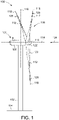
- FIG. 1 is a schematic view of an exemplary wind turbine 100 that is monitored and controlled through a wind turbine control system 200 (shown in FIG. 2 ).
- wind turbine 100 is a horizontal axis wind turbine.
- a power generation system may be substituted for wind turbine 100, and a power generation system includes a gas turbine, steam turbine, hydroelectric turbine, compressor, generator, wind turbine, or any other system that produces power.
- Wind turbine 100 includes a tower 102 extending from a supporting surface 104, a nacelle 106 coupled to tower 102, and a rotor 108 coupled to nacelle 106.
- Rotor 108 has a rotatable hub 110 and a plurality of rotor blades 112 coupled to hub 110.
- rotor 108 has three rotor blades 112.
- rotor 108 has any number of rotor blades 112 that enables wind turbine 100 to function as described herein.
- tower 102 is fabricated from tubular steel and has a cavity (not shown in FIG. 1 ) extending between supporting surface 104 and nacelle 106.
- tower 102 is any tower that enables wind turbine 100 to function as described herein including, but not limited to, a lattice tower.
- the height of tower 102 is any value that enables wind turbine 100 to function as described herein.
- Blades 112 are positioned about rotor hub 110 to facilitate rotating rotor 108, thereby transferring kinetic energy from wind 124 into usable mechanical energy, and subsequently, electrical energy.
- Rotor 108 and nacelle 106 are rotated about tower 102 on a yaw axis 116 to control the perspective of blades 112 with respect to the direction of wind 124.
- Blades 112 are mated to hub 110 by coupling a blade root portion 120 to hub 110 at a plurality of load transfer regions 122.
- Load transfer regions 122 have a hub load transfer region and a blade load transfer region (both not shown in FIG. 1 ). Loads induced in blades 112 are transferred to hub 110 via load transfer regions 122.
- Each of blades 112 also includes a blade tip portion 125.
- blades 112 have a length between 50 meters (m) (164 feet (ft)) and 100 m (328 ft), however these characteristics form no limitations to the instant disclosure.
- blades 112 have any length that enable wind turbine to function as described herein.
- aerodynamic forces (not shown) are induced on each of blades 112 and rotation of rotor 108 about rotation axis 114 is induced as blade tip portions 125 are accelerated.
- reference numeral 124 is generally representative of wind. Since wind 124 is distributed spatially and temporally, wind speed varies significantly at different points over the area swept by wind turbine blades 112. Therefore, different portions of wind turbine 100 experience different wind speeds.
- the pitch angles of blades 112 are adjusted about a pitch axis 118 for each of blades 112. In the exemplary embodiment, the pitch angles of blades 112 are controlled individually. Alternatively, blade 112 pitch is controlled as a group. Still further alternatively, the pitch of the blades are modulated.
- FIG. 2 is a schematic view of an exemplary wind turbine control system 200.
- system 200 includes sensors 240 located proximate to, in, within, on, or otherwise attached to, at least one component of at least one wind turbine 100 in a wind farm 202.
- wind turbine control system 200 includes wind farm controller 204 and a plurality of wind turbine controllers 250 coupled to wind farm controller 404.
- Sensors 240 are coupled to computing device 205 through a network 206 or data transmission cable 206.
- Wind farm controller 204 primarily controls each wind turbine 100 in wind farm 202 through wind turbine controllers 250 as a function of an inferred, detected or calculated or estimated wind characteristic/condition, such as wind shear, based on analyses by computing device 105, or by other operational or environmental characteristics/conditions (e.g., wind turbine load data, wind speed, wind shear, wind turbulence, generator speed, and air temperature). This may include regulating the angular rotor speed (revolutions per minute, i.e., rpm) and pitch angles of blades 112 about pitch axis 118 (both shown in FIG. 1 ).
- Computing device 205 is configured to generate and transmit at least one wind turbine command signal to wind farm controller 204.
- Wind farm controller 204 transmits the command signal to wind turbine controllers 250 to regulate operation of wind turbines 100 in wind farm 202.
- computing device 205 can transmit command signals directly to individual wind turbine controllers 250.
- wind farm control system 200 does not include wind farm controller 204 and computing device 205 communicates directly with wind turbine controllers 250.
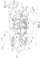
- FIG. 3 is a cross-sectional schematic view of nacelle 106 of exemplary wind turbine 100.
- Various components of wind turbine 100 are housed in nacelle 106 atop tower 102 of wind turbine 100.
- Nacelle 106 includes one pitch drive mechanism (or pitch system) 330 that is coupled to one blade 112 (shown in FIG. 1 ), where mechanism 330 modulates the pitch of associated blade 112 along pitch axis 118.
- the pitch drive mechanism 330 includes at least one pitch drive motor 331.
- Nacelle 106 also includes a rotor 108 that is rotatably coupled to an electric generator 332 positioned within nacelle 106 via rotor shaft 334, a gearbox 336, a high speed shaft 338, and a coupling 340.
- Rotation of shaft 334 rotatably drives gearbox 336 that subsequently rotatably drives shaft 338.
- Shaft 338 rotatably drives generator 332 via coupling 340 and shaft 338 rotation facilitates generator 332 production of electrical power.
- Gearbox 336 and generator 332 are supported by supports 342 and 344, respectively.
- gearbox 336 utilizes a dual path geometry to drive high speed shaft 338.
- main rotor shaft 334 is coupled directly to generator 332 via coupling 340.
- Nacelle 106 further includes a yaw adjustment mechanism 346 that is used to rotate nacelle 106 and rotor 108 on an axis to control the perspective of blades 112 with respect to the direction of the wind.
- Nacelle 106 also includes at least one meteorological mast 348, where mast 348 includes a wind vane and anemometer. Mast 348 provides information to a turbine control system (not shown) that includes wind direction and/or wind speed.
- Nacelle 106 further includes forward and aft support bearings 352 and 354, respectively, where bearings 352 and 354 facilitate radial support and alignment of shaft 334.
- Wind turbine 100 includes a pitch control system 360, where at least a portion of pitch control system 360 is positioned in nacelle 106, or alternatively, outside nacelle 106.
- pitch control system 360 described herein includes at least one wind turbine regulation device, i.e., processor 362 and a memory device (not shown), and at least one input/output (I/O) conduit 364, where conduit 364 includes at least one I/O channel (not shown). More specifically, processor 362 is positioned within control panel 350.
- Processor 362 and other processors (not shown) as described herein process information transmitted from a plurality of electrical and electronic devices that includes, but not be limited to, blade pitch position feedback devices 366 (described further below) and electric power generation feedback devices (not shown).
- RAM and storage devices store and transfer information and instructions to be executed by processor 362.
- RAM and storage devices can also be used to store and provide temporary variables, static (i.e., non-changing) information and instructions, or other intermediate information to processor 362 during execution of instructions by processor 362. Instructions that are executed include, but are not limited to, resident blade pitch system control commands. The execution of sequences of instructions is not limited to any specific combination of hardware circuitry and software instructions.
- pitch control system 360 including, but not limited to, processor 362 is positioned within control panel 350. Moreover, processor 362 is coupled to blade pitch drive motors 331 via at least one I/O conduit 364. I/O conduit 364 includes any number of channels having any architecture including, but not limited to, Cat 5/6 cable, twisted pair wiring, and wireless communication features. Pitch control system 360 includes distributed and/or centralized control architectures, or any combination thereof.
- Pitch control system 360 also includes a plurality of independent blade pitch position feedback devices 366 coupled with processor 362 via at least one I/O conduit 364.
- each pitch drive mechanism 330 is associated with a single blade pitch position feedback device 366 (also known as a blade pitch position device or a position feedback device).
- any number of blade pitch position feedback devices 366 are associated with each mechanism 330. Therefore, in the exemplary embodiment, mechanism 330 and associated drive motor 331, as well as device 366, are included in system 360 as described herein.
- Each blade pitch position feedback device 366 measures a pitch position of each blade 112 with respect to rotor hub 110.
- Blade pitch position feedback device 366 is any suitable sensor having any suitable location within or remote to wind turbine 100, such as, but not limited to, optical angle encoders, magnetic rotary encoders, and incremental encoders, or some combination thereof. Moreover, blade pitch position feedback device 366 transmits pitch measurement signals (not shown) that are substantially representative of associated blade 112 pitch position to processor 362 for processing thereof.
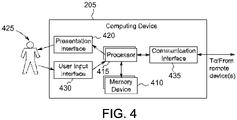
- FIG. 4 is a block diagram of an exemplary computing device 205 used to infer, estimate, calculate or obtain one or more characteristics/conditions based on sensor measurements received from one or more sensors.
- computing device 205 is used to infer one or more environmental characteristics/conditions or operating conditions based on sensor measurements received from one or more sensors in or on a wind turbine.
- computing device 205 is further used to facilitate operation of a wind turbine through a wind turbine control system.
- Computing device 205 controls the operation of the wind turbine at least partially using the one or more environmental characteristics or operating conditions.
- Computing device 205 includes a memory device 410 and a processor 415 operatively coupled to memory device 410 for executing instructions.
- executable instructions are stored in memory device 410.
- Computing device 205 is configurable to perform one or more operations described herein by programming processor 415.
- processor 415 may be programmed by encoding an operation as one or more executable instructions and providing the executable instructions in memory device 410.
- memory device 410 is one or more devices that enable storage and retrieval of information such as executable instructions and/or other data.
- Memory device 410 may include one or more computer readable media.
- Memory device 410 is configured to store sensor data.
- memory device 410 stores, without limitation, atmospheric condition measurements, wind turbine operational data, mechanical load measurements, blade pitch angle measurements, and/or any other type data.
- memory device 410 includes, without limitation, sufficient data, algorithms, and commands to facilitate (i) generating data-driven classifications of a profile from the sensor data to determine an appropriate physics-based model from which the one or more characteristics are inferred, (ii) inferring the one or more characteristics from the model, and (iii) using the one or more characteristics to regulate a dynamic system.
- memory device 410 includes, without limitation, sufficient data, algorithms, and commands to facilitate (a) generating data-driven classifications of a wind profile from the sensor data to determine an appropriate model from which the one or more wind characteristics are inferred, (b) inferring the one or more wind characteristics from the model, and (c) using the one or more wind characteristics to regulate the wind turbine.
- computing device 205 includes a presentation interface 420 coupled to processor 415.
- Presentation interface 420 presents information to a user 425.
- presentation interface 420 includes one or more display devices and presents, for example, sensor data and/or characteristics to user 425 using a human machine interface (HMI) (not shown in FIG. 4 ).
- computing device 205 includes a user input interface 430.
- user input interface 430 is coupled to processor 415 and receives input from user 425.
- a communication interface 435 is coupled to processor 415 and is configured to be coupled in communication with one or more other devices, such as one or more sensors, a wind turbine control device, or another computing device 205, and to perform input and output operations with respect to such devices while performing as an input channel.
- Communication interface 435 receives data from and/or transmits data to one or more remote devices.
- a communication interface 435 of computing device 205 transmits a signal to the communication interface 435 of another computing device 205.
- communication interface 435 is a wireless interface.
- computing device 205 is used to facilitate operation of a plurality of wind turbines through a wind farm controller.
- computing device 205 includes sufficient computer-readable/executable instructions, data structures, program modules, and program sub-modules, to receive other data associated with measured values from other wind turbines and wind turbine systems to facilitate overall operation of the wind turbine park.
- FIG. 5 is an exemplary block diagram of a portion of a wind turbine control system 500 that infers, estimates, calculates or detects one or more wind characteristics and operating conditions using one or more monitoring sensors 240 (also known as measurement sensors) on a wind turbine 100.
- Wind turbine control system 500 is further used to control at least a portion of wind turbine 100.
- wind turbine control system 500 obtains at least one of, wind turbine load data, wind speed, wind shear, wind turbulence, generator speed, and air temperature, as described below.
- wind turbine control system 500 includes sufficient computer-readable/executable instructions, data structures, program modules, and program sub-modules, to receive other data associated with measured values from other wind turbine systems to facilitate overall operation of wind turbine 100.
- wind turbine control system 500 is a stand-alone system.
- wind turbine control system 500 is any computer-based system that monitors portions of, and infers one or more wind and operating characteristics/conditions for wind turbine 100.
- wind turbine control system 500 includes computing device 205 configured to execute monitoring algorithms and monitoring logic.
- Computing device 205 is coupled to other devices 520 via a network 525.
- network 525 is a wireless network.
- computing device 205 is coupled to network 525 via communication interface 535. In an alternative embodiment, computing device 205 is integrated with other devices 520.
- wind turbine 100 includes one or more monitoring sensors 240 coupled to computing device 205 through at least one input channel 206.
- Sensors 240 include one or more mechanical load sensors 542 for obtaining load measurements.
- Sensors 240 may also include one or more blade pitch angle sensors 544 for obtaining blade pitch angle measurements, one or more atmospheric condition sensors 546 for obtaining atmospheric condition measurements, and/or one or more operational data sensors 548 for obtaining operational data measurements.
- Sensors 240 collect measurements including, without limitation, yaw, nod, pitch, multi-blade coordinate (MBC) estimated wind speed, electric output, bending moments, torsional moments, and rotations per minute (RPM) emanating from portions of wind turbine 100.
- MPC multi-blade coordinate
- Sensors 240 produce measurement sensorsignals of wind turbine 100 that are transmitted to computing device 205. Such data is transmitted across network 525 and is accessed by any device capable of accessing network 525 including, without limitation, desktop computers, laptop computers, and personal digital assistants (PDAs) (neither shown).
- PDAs personal digital assistants
- Sensors 240 repeatedly, e.g., periodically, continuously, and/or upon request, transmit measurement readings at the time of measurement.
- any number of measurements, any interval time, and any time window are established that enable operation of wind turbine 100 and wind turbine control system 500 as described above.
- computing device 205 is configured to obtain a wind shear characteristic.
- Computing device 205 classifies a shear profile derived from one or more sensor measurements. Based on the shear profile, computing device 205 determines an appropriate model from which the shear characteristic should be estimated. Computing device 205 then estimates the shear characteristic from the model.
- computing device 205 uses a supervised machine learning method, such as a random forest algorithm, on the sensor measurement data to classify whether the shear profile behaves according to a wind shear power law profile (as is normally assumed) or whether the profile is low level jet (where lower speed is experienced at higher elevation) or flat speed distribution (where higher elevation speed exceeds a power law prediction).
- a supervised machine learning method such as a random forest algorithm
- the shear profile is classified using a random forests model that has been previously trained on historical data where sensors at, in one embodiment, five different elevations are configured to record prime standard wind speeds (for example, from a multi sensor Metmast or Lidar/Sodar).
- the random forest algorithm grows multiple decision trees. These multiple decision trees are sometimes referred to as an ensemble of trees or a random forest.
- real time loads information is then applied to the ensemble of trees to obtain a classification about whether the shear profile behaves according to a power law or if a different shear profile is in effect.
- the characteristics of the shear model can be determined from the data. If the profile is a power law profile, a single characteristic ⁇ (alpha) characterizes the shear profile.
- the wind shear exponent ⁇ can be determined from the data by minimizing a fitting error metric, eg., mean squared error, between the training data and the power law shear profile.
- ⁇ varies with such characteristics as elevation, time of day, season, temperature, terrain, and atmospheric stability.
- a larger exponent means a larger vertical gradient in the wind speed. If computing device 205 determines that the shear profile is consistent with the power law, the wind shear exponent ⁇ is inferred as the wind shear characteristic.
- computing device 205 determines that the shear profile does not behave according to the wind profile power law, computing device 205 uses a fitted quadratic model with a and b characteristics in a quadratic fit.
- the fitted quadratic model represents a low level jet (LLJ) stream or a flat (near linear) speed distribution.
- the fitted quadratic model fits one quadratic function (a i , b i ) of shear to five different elevations of wind speed, where i represents the elevation.
- Characteristics a i and b i are the coefficients of the quadratic model, where a represents curvature and b represents the slope.
- the characteristic b is close to ⁇ (alpha) when the wind profile is close to the power law.
- characteristics a i and b i are determined by minimizing mean squared error between actual velocity measurements determined by sensors 240 over a range of altitudes and predicted velocities over the range of altitudes.
- the curvature coefficient a will be small for a flat profile and larger for a low level jet profile.
- computing device 105 is configured to identify ⁇ or the quadratic characteristics independent of the type of profile.
- the step of identifying the type of profile (for example, power law, LLJ, or flat) is not performed after inferring the characteristic(s).
- the shear profiles are driven by different power differentials.
- a power differential is defined as the difference in power from that which is expected given some objective reference.
- wind turbines are generally described by wind power curves that provide the expectation of power given a wind speed as input. Power differential in this context would be ((P actual - P expected )
- Other objective references can be used to generate power differential, such as control turbine power, etc.
- the method described herein can use any power differential metric driven by any objective source.
- the power law describes normal shear.
- the low-level jet stream profile has lower energy than the corresponding power law based on measurement up to hub height (wind speed decreases with height).
- the flat jet stream describes a flatter shear curve than the power law, resulting in higher energy in the wind profile (wind speed increases with height at a sharper rate than normal shear).
- the operation of the wind turbine can be enhanced depending on the wind conditions described by the shear profile.
- Computing device 205 is further configured to generate at least one wind turbine regulation device command signal based upon the inferred wind shear characteristic. Computing device 205 is also further configured to transmit the at least one wind turbine command signal to wind turbine regulation device 250.
- Wind turbine controller 250 is configured to receive the at least one wind turbine command signal to regulate operation of wind turbine 100.
- Wind turbine controller 250 includes, but is not limited to, a pitch regulator to adjust blade pitch, a torque regulator to modulate torque in a drive train, a yaw regulator to modify a yaw position of wind turbine 100, and a mechanical brake regulator to engage a braking device for the drive train.
- Regulating the operation of wind turbine 100 includes, but is not limited to, controlling the yaw of wind turbine 100, controlling the pitch of at least one of the turbine blades, controlling the power electronic converters connected to the turbine generator, controlling the power generated by wind turbine 100, controlling the rotational speed of the turbine rotor, and controlling the torque of wind turbine 100.
- the wind turbine regulation device command signal commands the wind turbine regulation device to change the pitch of one or more rotor blade to enhance the torque or lower the loads given a particular wind shear profile.
- the technical effects of using an inferred wind characteristic to at least partially control the wind turbine includes, without limitation, increasing energy production, improving life of wind turbine components, validating performance, improving fine pitch control, troubleshooting issues, and providing general information capabilities.
- the inferred wind shear characteristic is used to increase energy production by fine pitch control or other turbine control methods, provide insight to reduce unnecessary protective tripping or curtailment that are not appropriate for the given shear profile, and/or for farm level optimization.
- wind turbine control system 500 described herein facilitates enhanced control of wind turbine 100 and/or a plurality of wind turbines 100 in a wind farm.
- the embodiments described herein facilitate enhanced control of the wind turbine through determinations of real-time, day-to-day, and seasonal estimates of wind flow in a wind turbine site.
- the embodiments described herein facilitate enhancing power generation performance and increasing annual energy production (AEP) by taking into account the time-dependent inflow variables such as wind turbine configuration changes including turbine outages and blade contamination and erosion.
- AEP annual energy production
- a wind characteristic could also be inferred for, but not limited to, directional variations, wind speed at various heights, veer, turbulence intensity, yaw misalignment, upflow, horizontal shear, waked state, and non-waked state.
- These wind characteristics could have one or more profiles that could be described by one or more models, including, but not limited to, a power law model.
- one or more wind characteristics are inferred using a known single parameter model, such as a linear model or a power law.
- shear is generally described using a single characteristic model and the classification step identifies when the model is inadequate.
- other characteristics may be characterized as well by models.
- the systems and methods described herein use a single characteristic model to infer at least one characteristic.
- the at least one characteristic includes, but is not limited to, a wind shear characteristic.
- the method is generalizable and scalable beyond shear.
- profile classification e.g. power law, low level jet, or flat jet
- turbine underperformance may be emphasized, without a need to accurately model the exact shear profile.
- profile classification is not as important as the characteristic inference.
- the described systems and methods provide flexibility for both.
- Computing device 205 interacts with a first operator 530, e.g., without limitation, via user input interface 430 and/or presentation interface 420.
- computing device 205 presents information about wind turbine 100, such as measured blade pitch positions, to operator 530.
- Other devices 520 interact with a second operator 532, e.g., without limitation, via user input interface 430 and/or presentation interface 420.
- other devices 520 present operational information to second operator 532.
- the term "operator” includes any person in any capacity associated with operating and maintaining wind turbine 100, including, without limitation, shift operations personnel, maintenance technicians, and facility supervisors.
- FIG. 6 is a schematic view of a method 600 to control operation of a wind turbine 100.
- the method 600 makes use of a function to determine the power output level or change in power output level of the wind turbine. For example, the following equation may be used.
- Y F Pitch Setpoint , TSR Setpoint , X obs
- Y is the single wind turbine power differential versus a baseline.
- F is a prediction function
- Pitch Setpoint is the pitch setting of the turbine blades
- TSR Setpoint is the tip speed ratio of the rotor
- X obs is the available environmental observation variables and/or machine operating variables.
- environmental observation variables are wind speed, wind direction, wind shear, wind turbulence, and air temperature
- machine operating variables are wind turbine load data, and generator speed.
- Method 600 collects training data for equation 3 above in step 610.
- the environmental observations and operating conditions of the wind turbine are obtained over a period of time.
- the collection may occur over a time period of about one to six months, and at intervals between measurements of about one minute to one hour.
- the training data includes pitch setpoint, tip speed ratio setpoint, and historical data regarding environmental and operational conditions of the wind turbine.
- the data regarding an operational condition of the wind turbine may be a direct measurement of or an indirect estimation of wind turbine load data, power output, wind speed, wind shear, wind turbulence, wind direction, yaw misalignment, generator speed, air density and/or air temperature.
- step 620 the function of equation 3 is trained with the data obtained in step 610.
- the training data (acquired in step 610) is applied to the function (equation 3) that determines an estimated power output or power differential of the wind turbine based on the training data and multiple wind speeds.
- Outputs of the function are stored in a machine learning model.
- the training step 620 is performed via a machine learning model/algorithm or statistical regression algorithm using one of support vector machines, gaussian processes, or random forest, neural networks, Bayesian regression, linear regression or non-linear regression.
- the value of Y is calculated for each pitch and tip speed ratio setpoint combination to optimize the maximum value of Y.
- step 630 a determination of the optimal wind turbine settings for the various X obs variables is made. For example, based on one or more of wind speed, wind shear, wind turbulence, air temperature, wind turbine loads, and generator speed, the optimal (or at least improved) settings for pitch setpoint and tip speed ratio are determined.
- the output of step 630 is a machine learning model that can be deployed on an individual turbine that provides the ability to compare output from various controllable settings given an input vector X obs .
- step 640 recent (which includes current) data regarding environmental and/or operational conditions of the wind turbine is obtained.
- a current value of the data is the value just (most recently) obtained from one or more sensors, and a recent value of the data is obtained within one hour of the present time.
- optimal turbine settings are determined by applying the recent data to the machine learning model to obtain a current estimated power output or power differential of the wind turbine for all options of controllable settings.
- the machine learning model exercised with the current X obs input enables the counterfactual question be answered, "What would the power differential be if the control settings for pitch and tip speed ratio were various different values?".
- a comparing step compares one of the current estimated power output or reference power differential to a current power output or estimated power differential of the wind turbine.
- the turbine setting is applied (in step 670) to the wind turbine if the estimated power output or estimated power differential is greater than or equal to a threshold amount above the current power output or reference power differential.
- the threshold amount may be 10% of a current value or 10 kW.
- the threshold amount may be any desired percentage or fraction of the power output or power differential, or the threshold amount may be any power value as desired in the specific application (e.g., more or less than 10 kW).
- the turbine settings may be adjustments to blade pitch and/or tip speed ratio. There is a balancing act between power output increase versus wear and tear on the wind turbine components.
- step 670 if the threshold criteria are met the optimal setting, if different from the current setting, is applied to the turbine controls. When method 600 is applied to a single wind turbine, the annual energy production of that turbine can see substantial increases.
- step 680 the method cycles back to step 640 to repeat the obtaining, determining and comparing steps at a predetermined time interval.
- the predetermined time interval may be about 10 seconds to about 1 hour.
- An exemplary technical effect of the method described herein includes at least one of: (a) increased annual energy production; (b) real-time knowledge of wind and environmental conditions on a wind turbine site is used in control strategies for one or more of the following: enhancing power generation performance, increasing annual energy production (AEP), and reducing mechanical loads; (c) increasing the accuracy in predicting the power performance and loads of wind turbines under different wind conditions; (d) improving a life span of mechanical components, including wind turbine components; (e) troubleshooting issues; (f) providing general information capabilities; (g) providing insight to reduce unnecessary protective tripping or curtailment of wind turbines that is not appropriate for a given wind profile; and (h) wind farm level optimization.
- Some embodiments involve the use of one or more electronic or computing devices.
- Such devices typically include a processor or controller, such as a general purpose central processing unit (CPU), a graphics processing unit (GPU), a microcontroller, a reduced instruction set computer (RISC) processor, an application specific integrated circuit (ASIC), a programmable logic circuit (PLC), and/or any other circuit or processor capable of executing the functions described herein.
- the methods described herein may be encoded as executable instructions embodied in a computer readable medium, including, without limitation, a storage device and/or a memory device. Such instructions, when executed by a processor, cause the processor to perform at least a portion of the methods described herein.
- the above examples are exemplary only, and thus are not intended to limit in any way the definition and/or meaning of the term processor.
Claims (11)
- Procédé (600) permettant de commander le fonctionnement d'une turbine éolienne (100), le procédé comprenant :la collecte (610) de données d'apprentissage, les données d'apprentissage comprenant des consignes de pas, des consignes de rapport de vitesse de pointe et des données historiques concernant une ou plusieurs conditions de fonctionnement de la turbine éolienne, y compris une sortie de puissance ou un différentiel de puissance de la turbine éolienne ;la formation (620) d'un modèle d'apprentissage automatique en appliquant les données d'apprentissage au modèle d'apprentissage automatique, une sortie du modèle d'apprentissage automatique est une puissance différentielle estimée ou un différentiel de puissance estimé de la turbine éolienne sur la base des données d'apprentissage, et le modèle d'apprentissage automatique est stocké ;l'obtention (640) de données récentes concernant une ou plusieurs conditions de fonctionnement de la turbine éolienne ;l'application (650) du modèle d'apprentissage automatique aux données récentes pour délivrer une puissance de référence ou un différentiel de puissance de référence correspondant aux données récentes ;l'application (650) du modèle d'apprentissage automatique aux données récentes pour délivrer au moins une puissance estimée ou un différentiel de puissance estimé correspondent à des valeurs des consignes de pas et des consignes de rapport de vitesse de pointe qui diffèrent des données récentes ;la détermination (660) d'un réglage de la turbine éolienne en comparant la puissance estimée ou la différence de puissance estimée à la puissance de référence ou à la différence de puissance de référence, et l'application (670) du réglage de la turbine éolienne à la turbine éolienne si la puissance estimée ou la différence de puissance estimée est supérieure ou égale à une quantité seuil au-dessus de la puissance de référence ou de la différence de puissance de référence ; le fait de répéter (680) les étapes d'obtention, d'application et de détermination à un intervalle de temps prédéterminé.
- Procédé selon la revendication 1, dans lequel les données concernant un état opérationnel de la turbine éolienne (100) comprennent au moins l'un parmi des données de charge de turbine éolienne, une puissance de sortie, une vitesse du vent, une estimation de vitesse du vent, un cisaillement du vent, une turbulence du vent, une direction du vent, un désalignement de lacet, une vitesse de générateur, une densité d'air et une température d'air.
- Procédé selon l'une quelconque des revendications précédentes, dans lequel l'étape de collecte (610) comprend le fonctionnement de la turbine éolienne selon une séquence de consignes de pas différentes, et des consignes de rapport de vitesse de pointe.
- Procédé selon l'une quelconque des revendications précédentes, le réglage de turbine comprenant en outre au moins l'un parmi :
un pas des pales, un couple de générateur et un rapport de vitesse de pointe. - Procédé selon l'une quelconque des revendications précédentes, dans lequel la puissance de référence ou la différence de puissance de référence de la turbine éolienne est déterminée en comparant une sortie de puissance de la turbine éolienne (100) à une ou plusieurs turbines éoliennes voisines dans un parc éolien.
- Procédé selon l'une quelconque des revendications précédentes, dans lequel la puissance de référence ou la différence de puissance de référence de la turbine éolienne (100) est déterminée en comparant une sortie de puissance actuelle de la turbine éolienne à une sortie de puissance précédente ou future de la turbine éolienne où le point de consigne de pas et de rapport de vitesse de pointe a été réglé à des valeurs de référence répétées pendant l'étape de collecte.
- Procédé selon l'une quelconque des revendications précédentes, dans lequel une consigne de décalage de lacet est utilisée en plus de la consigne de pas et de la consigne de rapport de vitesse de pointe.
- Procédé selon l'une quelconque des revendications précédentes, dans lequel l'intervalle de temps prédéterminé est d'environ 10 secondes à environ 1 heure.
- Procédé selon l'une quelconque des revendications précédentes, dans lequel la quantité seuil est de 10 %.
- Procédé selon l'une quelconque des revendications précédentes, dans lequel la quantité seuil est de 10 kw.
- Procédé selon l'une quelconque des revendications précédentes, dans lequel l'étape d'apprentissage (620) est mise en oeuvre par l'intermédiaire d'un algorithme d'apprentissage automatique comprenant l'un parmi :
des machines à vecteurs de support, des processus gaussien pour l'apprentissage automatique, une forêt d'arbres décisionnels.
Applications Claiming Priority (1)
| Application Number | Priority Date | Filing Date | Title |
|---|---|---|---|
| US16/105,076 US10605228B2 (en) | 2018-08-20 | 2018-08-20 | Method for controlling operation of a wind turbine |
Publications (2)
| Publication Number | Publication Date |
|---|---|
| EP3613982A1 EP3613982A1 (fr) | 2020-02-26 |
| EP3613982B1 true EP3613982B1 (fr) | 2023-01-25 |
Family
ID=67659501
Family Applications (1)
| Application Number | Title | Priority Date | Filing Date |
|---|---|---|---|
| EP19192617.9A Active EP3613982B1 (fr) | 2018-08-20 | 2019-08-20 | Procédé de commande de fonctionnement d'une éolienne |
Country Status (4)
| Country | Link |
|---|---|
| US (1) | US10605228B2 (fr) |
| EP (1) | EP3613982B1 (fr) |
| DK (1) | DK3613982T3 (fr) |
| ES (1) | ES2942988T3 (fr) |
Families Citing this family (12)
| Publication number | Priority date | Publication date | Assignee | Title |
|---|---|---|---|---|
| CN109973301B (zh) * | 2017-12-28 | 2020-07-24 | 新疆金风科技股份有限公司 | 在极端湍流风况下控制风力发电机组变桨的方法和装置 |
| DE102018112825A1 (de) * | 2018-05-29 | 2019-12-05 | fos4X GmbH | Sensoranordnung für eine Windkraftanlage |
| US10815972B2 (en) * | 2019-03-22 | 2020-10-27 | General Electric Company | System and method for assessing and validating wind turbine and wind farm performance |
| DE102019108244A1 (de) * | 2019-03-29 | 2020-10-01 | Wobben Properties Gmbh | Verfahren zum Ermitteln einer Leistungskurve einer Windenergieanlage |
| FR3095246B1 (fr) * | 2019-04-16 | 2022-12-09 | Ifp Energies Now | Procédé et système de contrôle d’une grandeur d’une éolienne par choix du contrôleur par un apprentissage automatique |
| DE102019119774A1 (de) * | 2019-07-22 | 2021-01-28 | fos4X GmbH | Verfahren zur Steuerung eines Windparks, Steuerungsmodul für einen Windpark und Windpark |
| US11261846B2 (en) * | 2019-11-01 | 2022-03-01 | General Electric Company | System and method for designing and operating a wind turbine power system based on statistical analysis of operational and/or grid data thereof |
| EP3842635A1 (fr) * | 2019-12-23 | 2021-06-30 | Vestas Wind Systems A/S | Fonctionnement d'une éolienne avec des capteurs mis en oeuvre à l'aide d'un modèle d'apprentissage automatique |
| EP3964708A1 (fr) * | 2020-09-03 | 2022-03-09 | Nederlandse Organisatie voor toegepast- natuurwetenschappelijk Onderzoek TNO | Procédé et agencement de commande de fonctionnement d'un parc éolien |
| CN112594125A (zh) * | 2020-11-29 | 2021-04-02 | 上海电机学院 | 一种自动收缩的风力发电叶片及其控制方法 |
| US11649804B2 (en) * | 2021-06-07 | 2023-05-16 | General Electric Renovables Espana, S.L. | Systems and methods for controlling a wind turbine |
| EP4343140A1 (fr) * | 2022-09-23 | 2024-03-27 | Consiglio Nazionale delle Ricerche | Appareil éolien pour maximiser la quantité d'énergie cinétique associée à un flux d'air capturé au fil du temps par ledit appareil éolien |
Citations (8)
| Publication number | Priority date | Publication date | Assignee | Title |
|---|---|---|---|---|
| EP1873396A2 (fr) | 2006-06-30 | 2008-01-02 | General Electric Company | Système de production d'énergie éolienne et procédé de son fonctionnement |
| EP2878811A1 (fr) | 2013-11-29 | 2015-06-03 | Alstom Renovables España, S.L. | Procédé de fonctionnement d'une éolienne et éoliennes |
| EP3088733A1 (fr) | 2015-04-27 | 2016-11-02 | Envision Energy (Jiangsu) Co., Ltd. | Procédé pour faire fonctionner une éolienne sur la base de la dégradation de la pale de turbine éolienne |
| US20170350369A1 (en) | 2016-06-07 | 2017-12-07 | General Electric Company | System and method for controlling a dynamic system |
| WO2017211367A1 (fr) | 2016-06-07 | 2017-12-14 | Vestas Wind Systems A/S | Commande adaptative d'une turbine éolienne par détection d'un changement de performances |
| EP3260700A1 (fr) | 2016-06-22 | 2017-12-27 | Siemens Aktiengesellschaft | Procédé informatisé et dispositif de prévision pour données de fonctionnement d'une éolienne |
| WO2018006849A1 (fr) | 2016-07-06 | 2018-01-11 | Envision Energy (Jiangsu) Co., Ltd. | Éolienne et procédé d'exploitation d'une éolienne |
| WO2018121668A1 (fr) | 2016-12-30 | 2018-07-05 | Envision Energy (Jiangsu) Co., Ltd. | Procédé et système d'évaluation des performances d'un générateur éolien |
Family Cites Families (13)
| Publication number | Priority date | Publication date | Assignee | Title |
|---|---|---|---|---|
| ES2656542T3 (es) | 2007-08-31 | 2018-02-27 | Vestas Wind Systems A/S | Método para el control de al menos un mecanismo de regulación de una turbina eólica, una turbina eólica y un parque eólico |
| ES2329182T3 (es) | 2007-10-12 | 2009-11-23 | Siemens Aktiengesellschaft | Procedimiento y dispositivo para proporcionar al menos una señal de sensor de entrada para una aplicacion de control y/o monitorizacion y dispositivo de control. |
| WO2010057737A2 (fr) | 2008-11-18 | 2010-05-27 | Vestas Wind Systems A/S | Procédé de régulation du fonctionnement d’une éolienne |
| EP2213873A1 (fr) | 2009-01-30 | 2010-08-04 | Siemens Aktiengesellschaft | Estimation d'une direction effective du vent pour une éolienne au moyen d'un système d'apprentissage |
| ES2589384T3 (es) | 2010-06-02 | 2016-11-14 | Vestas Wind Systems A/S | Método de operación de una turbina eólica con salida de potencia mejorada |
| EP2444659B1 (fr) | 2010-10-19 | 2016-07-06 | Siemens Aktiengesellschaft | Procédé et système pour régler un paramètre d'opération d'une éolienne |
| US20130184838A1 (en) * | 2012-01-06 | 2013-07-18 | Michigan Aerospace Corporation | Resource optimization using environmental and condition-based monitoring |
| US9551322B2 (en) | 2014-04-29 | 2017-01-24 | General Electric Company | Systems and methods for optimizing operation of a wind farm |
| WO2015192856A1 (fr) | 2014-06-19 | 2015-12-23 | Vestas Wind Systems A/S | Commande d'éoliennes en réponse au cisaillement du vent |
| US9644612B2 (en) | 2014-09-23 | 2017-05-09 | General Electric Company | Systems and methods for validating wind farm performance measurements |
| US10473088B2 (en) | 2015-03-13 | 2019-11-12 | General Electric Company | System and method for variable tip-speed-ratio control of a wind turbine |
| US10712717B2 (en) * | 2015-05-15 | 2020-07-14 | General Electric Company | Condition-based validation of performance updates |
| ES2790835T3 (es) * | 2015-06-11 | 2020-10-29 | Vestas Wind Sys As | Potencia de variación en una turbina eólica usando planificación de ganancia |
-
2018
- 2018-08-20 US US16/105,076 patent/US10605228B2/en active Active
-
2019
- 2019-08-20 ES ES19192617T patent/ES2942988T3/es active Active
- 2019-08-20 EP EP19192617.9A patent/EP3613982B1/fr active Active
- 2019-08-20 DK DK19192617.9T patent/DK3613982T3/da active
Patent Citations (8)
| Publication number | Priority date | Publication date | Assignee | Title |
|---|---|---|---|---|
| EP1873396A2 (fr) | 2006-06-30 | 2008-01-02 | General Electric Company | Système de production d'énergie éolienne et procédé de son fonctionnement |
| EP2878811A1 (fr) | 2013-11-29 | 2015-06-03 | Alstom Renovables España, S.L. | Procédé de fonctionnement d'une éolienne et éoliennes |
| EP3088733A1 (fr) | 2015-04-27 | 2016-11-02 | Envision Energy (Jiangsu) Co., Ltd. | Procédé pour faire fonctionner une éolienne sur la base de la dégradation de la pale de turbine éolienne |
| US20170350369A1 (en) | 2016-06-07 | 2017-12-07 | General Electric Company | System and method for controlling a dynamic system |
| WO2017211367A1 (fr) | 2016-06-07 | 2017-12-14 | Vestas Wind Systems A/S | Commande adaptative d'une turbine éolienne par détection d'un changement de performances |
| EP3260700A1 (fr) | 2016-06-22 | 2017-12-27 | Siemens Aktiengesellschaft | Procédé informatisé et dispositif de prévision pour données de fonctionnement d'une éolienne |
| WO2018006849A1 (fr) | 2016-07-06 | 2018-01-11 | Envision Energy (Jiangsu) Co., Ltd. | Éolienne et procédé d'exploitation d'une éolienne |
| WO2018121668A1 (fr) | 2016-12-30 | 2018-07-05 | Envision Energy (Jiangsu) Co., Ltd. | Procédé et système d'évaluation des performances d'un générateur éolien |
Also Published As
| Publication number | Publication date |
|---|---|
| US20200056589A1 (en) | 2020-02-20 |
| US10605228B2 (en) | 2020-03-31 |
| DK3613982T3 (da) | 2023-03-13 |
| EP3613982A1 (fr) | 2020-02-26 |
| ES2942988T3 (es) | 2023-06-08 |
Similar Documents
| Publication | Publication Date | Title |
|---|---|---|
| EP3613982B1 (fr) | Procédé de commande de fonctionnement d'une éolienne | |
| EP3465359B1 (fr) | Système et procédé pour commander un système dynamique | |
| EP3317526B1 (fr) | Procédés et systèmes pour génération de programmes de commande de turbines éoliennes | |
| US10422319B2 (en) | Control method and system for wind turbines | |
| EP3317523B1 (fr) | Procédés et systèmes de génération de programmes de commande d'éolienne | |
| US9606518B2 (en) | Control system and method of predicting wind turbine power generation | |
| CN112219028B (zh) | 风力涡轮机控制方法 | |
| US9784241B2 (en) | System and method for controlling a wind turbine | |
| US11022100B2 (en) | System and method for controlling wind turbines | |
| US10907611B2 (en) | Methods and systems for generating wind turbine control schedules | |
| EP3317525B1 (fr) | Procédés et systèmes de génération de programmes de commande d'éolienne | |
| CN107810323B (zh) | 用于生成风力涡轮机控制安排的方法和系统 | |
| CN107850048B (zh) | 用于生成风力涡轮机控制安排的方法以及系统 | |
| CN107709765B (zh) | 用于生成风力涡轮机控制时间表的方法和系统 |
Legal Events
| Date | Code | Title | Description |
|---|---|---|---|
| PUAI | Public reference made under article 153(3) epc to a published international application that has entered the european phase |
Free format text: ORIGINAL CODE: 0009012 |
|
| STAA | Information on the status of an ep patent application or granted ep patent |
Free format text: STATUS: THE APPLICATION HAS BEEN PUBLISHED |
|
| AK | Designated contracting states |
Kind code of ref document: A1 Designated state(s): AL AT BE BG CH CY CZ DE DK EE ES FI FR GB GR HR HU IE IS IT LI LT LU LV MC MK MT NL NO PL PT RO RS SE SI SK SM TR |
|
| AX | Request for extension of the european patent |
Extension state: BA ME |
|
| STAA | Information on the status of an ep patent application or granted ep patent |
Free format text: STATUS: REQUEST FOR EXAMINATION WAS MADE |
|
| 17P | Request for examination filed |
Effective date: 20200825 |
|
| RBV | Designated contracting states (corrected) |
Designated state(s): AL AT BE BG CH CY CZ DE DK EE ES FI FR GB GR HR HU IE IS IT LI LT LU LV MC MK MT NL NO PL PT RO RS SE SI SK SM TR |
|
| STAA | Information on the status of an ep patent application or granted ep patent |
Free format text: STATUS: EXAMINATION IS IN PROGRESS |
|
| STAA | Information on the status of an ep patent application or granted ep patent |
Free format text: STATUS: EXAMINATION IS IN PROGRESS |
|
| 17Q | First examination report despatched |
Effective date: 20201016 |
|
| GRAP | Despatch of communication of intention to grant a patent |
Free format text: ORIGINAL CODE: EPIDOSNIGR1 |
|
| STAA | Information on the status of an ep patent application or granted ep patent |
Free format text: STATUS: GRANT OF PATENT IS INTENDED |
|
| INTG | Intention to grant announced |
Effective date: 20221010 |
|
| GRAS | Grant fee paid |
Free format text: ORIGINAL CODE: EPIDOSNIGR3 |
|
| GRAA | (expected) grant |
Free format text: ORIGINAL CODE: 0009210 |
|
| STAA | Information on the status of an ep patent application or granted ep patent |
Free format text: STATUS: THE PATENT HAS BEEN GRANTED |
|
| AK | Designated contracting states |
Kind code of ref document: B1 Designated state(s): AL AT BE BG CH CY CZ DE DK EE ES FI FR GB GR HR HU IE IS IT LI LT LU LV MC MK MT NL NO PL PT RO RS SE SI SK SM TR |
|
| REG | Reference to a national code |
Ref country code: GB Ref legal event code: FG4D |
|
| REG | Reference to a national code |
Ref country code: CH Ref legal event code: EP |
|
| REG | Reference to a national code |
Ref country code: AT Ref legal event code: REF Ref document number: 1546080 Country of ref document: AT Kind code of ref document: T Effective date: 20230215 Ref country code: IE Ref legal event code: FG4D |
|
| REG | Reference to a national code |
Ref country code: DE Ref legal event code: R096 Ref document number: 602019024719 Country of ref document: DE |
|
| REG | Reference to a national code |
Ref country code: DK Ref legal event code: T3 Effective date: 20230306 |
|
| REG | Reference to a national code |
Ref country code: LT Ref legal event code: MG9D |
|
| REG | Reference to a national code |
Ref country code: NL Ref legal event code: MP Effective date: 20230125 |
|
| REG | Reference to a national code |
Ref country code: ES Ref legal event code: FG2A Ref document number: 2942988 Country of ref document: ES Kind code of ref document: T3 Effective date: 20230608 |
|
| REG | Reference to a national code |
Ref country code: AT Ref legal event code: MK05 Ref document number: 1546080 Country of ref document: AT Kind code of ref document: T Effective date: 20230125 |
|
| PG25 | Lapsed in a contracting state [announced via postgrant information from national office to epo] |
Ref country code: NL Free format text: LAPSE BECAUSE OF FAILURE TO SUBMIT A TRANSLATION OF THE DESCRIPTION OR TO PAY THE FEE WITHIN THE PRESCRIBED TIME-LIMIT Effective date: 20230125 |
|
| P01 | Opt-out of the competence of the unified patent court (upc) registered |
Effective date: 20230530 |
|
| PG25 | Lapsed in a contracting state [announced via postgrant information from national office to epo] |
Ref country code: RS Free format text: LAPSE BECAUSE OF FAILURE TO SUBMIT A TRANSLATION OF THE DESCRIPTION OR TO PAY THE FEE WITHIN THE PRESCRIBED TIME-LIMIT Effective date: 20230125 Ref country code: PT Free format text: LAPSE BECAUSE OF FAILURE TO SUBMIT A TRANSLATION OF THE DESCRIPTION OR TO PAY THE FEE WITHIN THE PRESCRIBED TIME-LIMIT Effective date: 20230525 Ref country code: NO Free format text: LAPSE BECAUSE OF FAILURE TO SUBMIT A TRANSLATION OF THE DESCRIPTION OR TO PAY THE FEE WITHIN THE PRESCRIBED TIME-LIMIT Effective date: 20230425 Ref country code: LV Free format text: LAPSE BECAUSE OF FAILURE TO SUBMIT A TRANSLATION OF THE DESCRIPTION OR TO PAY THE FEE WITHIN THE PRESCRIBED TIME-LIMIT Effective date: 20230125 Ref country code: LT Free format text: LAPSE BECAUSE OF FAILURE TO SUBMIT A TRANSLATION OF THE DESCRIPTION OR TO PAY THE FEE WITHIN THE PRESCRIBED TIME-LIMIT Effective date: 20230125 Ref country code: HR Free format text: LAPSE BECAUSE OF FAILURE TO SUBMIT A TRANSLATION OF THE DESCRIPTION OR TO PAY THE FEE WITHIN THE PRESCRIBED TIME-LIMIT Effective date: 20230125 Ref country code: AT Free format text: LAPSE BECAUSE OF FAILURE TO SUBMIT A TRANSLATION OF THE DESCRIPTION OR TO PAY THE FEE WITHIN THE PRESCRIBED TIME-LIMIT Effective date: 20230125 |
|
| PG25 | Lapsed in a contracting state [announced via postgrant information from national office to epo] |
Ref country code: SE Free format text: LAPSE BECAUSE OF FAILURE TO SUBMIT A TRANSLATION OF THE DESCRIPTION OR TO PAY THE FEE WITHIN THE PRESCRIBED TIME-LIMIT Effective date: 20230125 Ref country code: PL Free format text: LAPSE BECAUSE OF FAILURE TO SUBMIT A TRANSLATION OF THE DESCRIPTION OR TO PAY THE FEE WITHIN THE PRESCRIBED TIME-LIMIT Effective date: 20230125 Ref country code: IS Free format text: LAPSE BECAUSE OF FAILURE TO SUBMIT A TRANSLATION OF THE DESCRIPTION OR TO PAY THE FEE WITHIN THE PRESCRIBED TIME-LIMIT Effective date: 20230525 Ref country code: GR Free format text: LAPSE BECAUSE OF FAILURE TO SUBMIT A TRANSLATION OF THE DESCRIPTION OR TO PAY THE FEE WITHIN THE PRESCRIBED TIME-LIMIT Effective date: 20230426 Ref country code: FI Free format text: LAPSE BECAUSE OF FAILURE TO SUBMIT A TRANSLATION OF THE DESCRIPTION OR TO PAY THE FEE WITHIN THE PRESCRIBED TIME-LIMIT Effective date: 20230125 |
|
| REG | Reference to a national code |
Ref country code: DE Ref legal event code: R026 Ref document number: 602019024719 Country of ref document: DE |
|
| PLBI | Opposition filed |
Free format text: ORIGINAL CODE: 0009260 |
|
| PG25 | Lapsed in a contracting state [announced via postgrant information from national office to epo] |
Ref country code: SM Free format text: LAPSE BECAUSE OF FAILURE TO SUBMIT A TRANSLATION OF THE DESCRIPTION OR TO PAY THE FEE WITHIN THE PRESCRIBED TIME-LIMIT Effective date: 20230125 Ref country code: RO Free format text: LAPSE BECAUSE OF FAILURE TO SUBMIT A TRANSLATION OF THE DESCRIPTION OR TO PAY THE FEE WITHIN THE PRESCRIBED TIME-LIMIT Effective date: 20230125 Ref country code: EE Free format text: LAPSE BECAUSE OF FAILURE TO SUBMIT A TRANSLATION OF THE DESCRIPTION OR TO PAY THE FEE WITHIN THE PRESCRIBED TIME-LIMIT Effective date: 20230125 Ref country code: CZ Free format text: LAPSE BECAUSE OF FAILURE TO SUBMIT A TRANSLATION OF THE DESCRIPTION OR TO PAY THE FEE WITHIN THE PRESCRIBED TIME-LIMIT Effective date: 20230125 |
|
| PGFP | Annual fee paid to national office [announced via postgrant information from national office to epo] |
Ref country code: ES Payment date: 20230901 Year of fee payment: 5 |
|
| PLAX | Notice of opposition and request to file observation + time limit sent |
Free format text: ORIGINAL CODE: EPIDOSNOBS2 |
|
| 26 | Opposition filed |
Opponent name: WOBBEN PROPERTIES GMBH Effective date: 20231025 |
|
| PG25 | Lapsed in a contracting state [announced via postgrant information from national office to epo] |
Ref country code: SK Free format text: LAPSE BECAUSE OF FAILURE TO SUBMIT A TRANSLATION OF THE DESCRIPTION OR TO PAY THE FEE WITHIN THE PRESCRIBED TIME-LIMIT Effective date: 20230125 |
|
| PGFP | Annual fee paid to national office [announced via postgrant information from national office to epo] |
Ref country code: DK Payment date: 20230721 Year of fee payment: 5 Ref country code: DE Payment date: 20230720 Year of fee payment: 5 |
|
| REG | Reference to a national code |
Ref country code: DE Ref legal event code: R082 Ref document number: 602019024719 Country of ref document: DE Representative=s name: ZIMMERMANN & PARTNER PATENTANWAELTE MBB, DE Ref legal event code: R082 Ref document number: 602019024719 Ref country code: DE Ref legal event code: R081 Ref document number: 602019024719 Country of ref document: DE Owner name: GENERAL ELECTRIC RENOVABLES ESPANA, S.L., ES Free format text: FORMER OWNER: GENERAL ELECTRIC COMPANY, SCHENECTADY, NY, US |
|
| PG25 | Lapsed in a contracting state [announced via postgrant information from national office to epo] |
Ref country code: SI Free format text: LAPSE BECAUSE OF FAILURE TO SUBMIT A TRANSLATION OF THE DESCRIPTION OR TO PAY THE FEE WITHIN THE PRESCRIBED TIME-LIMIT Effective date: 20230125 |
|
| PLBB | Reply of patent proprietor to notice(s) of opposition received |
Free format text: ORIGINAL CODE: EPIDOSNOBS3 |
|
| PG25 | Lapsed in a contracting state [announced via postgrant information from national office to epo] |
Ref country code: MC Free format text: LAPSE BECAUSE OF FAILURE TO SUBMIT A TRANSLATION OF THE DESCRIPTION OR TO PAY THE FEE WITHIN THE PRESCRIBED TIME-LIMIT Effective date: 20230125 |
|
| REG | Reference to a national code |
Ref country code: DE Ref legal event code: R082 Ref document number: 602019024719 Country of ref document: DE Representative=s name: ZIMMERMANN & PARTNER PATENTANWAELTE MBB, DE Ref country code: CH Ref legal event code: PL |
|
| PG25 | Lapsed in a contracting state [announced via postgrant information from national office to epo] |
Ref country code: MC Free format text: LAPSE BECAUSE OF FAILURE TO SUBMIT A TRANSLATION OF THE DESCRIPTION OR TO PAY THE FEE WITHIN THE PRESCRIBED TIME-LIMIT Effective date: 20230125 |
|
| PG25 | Lapsed in a contracting state [announced via postgrant information from national office to epo] |
Ref country code: LU Free format text: LAPSE BECAUSE OF NON-PAYMENT OF DUE FEES Effective date: 20230820 |