EP1993403B1 - Siège avec une plaque d'assise et un dossier - Google Patents
Siège avec une plaque d'assise et un dossier Download PDFInfo
- Publication number
- EP1993403B1 EP1993403B1 EP07846877A EP07846877A EP1993403B1 EP 1993403 B1 EP1993403 B1 EP 1993403B1 EP 07846877 A EP07846877 A EP 07846877A EP 07846877 A EP07846877 A EP 07846877A EP 1993403 B1 EP1993403 B1 EP 1993403B1
- Authority
- EP
- European Patent Office
- Prior art keywords
- seat
- seat according
- levers
- panel
- rod
- Prior art date
- Legal status (The legal status is an assumption and is not a legal conclusion. Google has not performed a legal analysis and makes no representation as to the accuracy of the status listed.)
- Active
Links
- 238000013016 damping Methods 0.000 claims description 2
- 239000000463 material Substances 0.000 claims description 2
- 210000003127 knee Anatomy 0.000 description 3
- TVEXGJYMHHTVKP-UHFFFAOYSA-N 6-oxabicyclo[3.2.1]oct-3-en-7-one Chemical compound C1C2C(=O)OC1C=CC2 TVEXGJYMHHTVKP-UHFFFAOYSA-N 0.000 description 1
- 238000000605 extraction Methods 0.000 description 1
- 239000012858 resilient material Substances 0.000 description 1
Images


Classifications
-
- A—HUMAN NECESSITIES
- A47—FURNITURE; DOMESTIC ARTICLES OR APPLIANCES; COFFEE MILLS; SPICE MILLS; SUCTION CLEANERS IN GENERAL
- A47C—CHAIRS; SOFAS; BEDS
- A47C1/00—Chairs adapted for special purposes
- A47C1/02—Reclining or easy chairs
- A47C1/031—Reclining or easy chairs having coupled concurrently adjustable supporting parts
- A47C1/032—Reclining or easy chairs having coupled concurrently adjustable supporting parts the parts being movably-coupled seat and back-rest
- A47C1/03255—Reclining or easy chairs having coupled concurrently adjustable supporting parts the parts being movably-coupled seat and back-rest with a central column, e.g. rocking office chairs
-
- A—HUMAN NECESSITIES
- A47—FURNITURE; DOMESTIC ARTICLES OR APPLIANCES; COFFEE MILLS; SPICE MILLS; SUCTION CLEANERS IN GENERAL
- A47C—CHAIRS; SOFAS; BEDS
- A47C1/00—Chairs adapted for special purposes
- A47C1/02—Reclining or easy chairs
- A47C1/031—Reclining or easy chairs having coupled concurrently adjustable supporting parts
- A47C1/032—Reclining or easy chairs having coupled concurrently adjustable supporting parts the parts being movably-coupled seat and back-rest
- A47C1/03261—Reclining or easy chairs having coupled concurrently adjustable supporting parts the parts being movably-coupled seat and back-rest characterised by elastic means
- A47C1/03288—Reclining or easy chairs having coupled concurrently adjustable supporting parts the parts being movably-coupled seat and back-rest characterised by elastic means with resilient blocks
-
- A—HUMAN NECESSITIES
- A47—FURNITURE; DOMESTIC ARTICLES OR APPLIANCES; COFFEE MILLS; SPICE MILLS; SUCTION CLEANERS IN GENERAL
- A47C—CHAIRS; SOFAS; BEDS
- A47C1/00—Chairs adapted for special purposes
- A47C1/02—Reclining or easy chairs
- A47C1/031—Reclining or easy chairs having coupled concurrently adjustable supporting parts
- A47C1/032—Reclining or easy chairs having coupled concurrently adjustable supporting parts the parts being movably-coupled seat and back-rest
- A47C1/03294—Reclining or easy chairs having coupled concurrently adjustable supporting parts the parts being movably-coupled seat and back-rest slidingly movable in the base frame, e.g. by rollers
Definitions
- the invention relates to a seat with a seat plate and a backrest, wherein the seat plate is connected to a first connecting means with a base means and adjustable relative to the base means in height and at the same time in the inclination and in the seat longitudinal direction, wherein the backrest by means of a second connecting means the seat plate is connected and simultaneously adjustable with the seat plate in the inclination and in the height, wherein the first connection means laterally opposite a pair of front side and a pair of rear side connecting lever, wherein the front kaushebei are longer than the rear side connecting lever, and wherein the back Connection lever are each formed with an angled extension as a toggle lever.
- Such a seat is eg off DE 30 27 311 known.
- the invention has for its object to realize such a seat structurally simple design with optimal seating comfort.
- connection means laterally opposite a pair of rod members which are pivotally and linearly mounted with its front end to the seat plate, and pivotally connected to the angled extension of the rear connecting lever are.
- the two laterally opposite front side connecting lever and the two laterally opposite rear connecting lever form between the base device and the seat plate quasi a parallelogram linkage, which is achieved by the dimensions of the front and the rear link that when pivoting the connecting lever the Seat plate relative to the base device is moved from an at least approximately horizontal position in the seat longitudinal direction to the front above and with its rear part down.
- the backrest is adjusted with its lower part forward and with its shoulder portion to the rear. In this way, a good seating comfort results, at the same time the so-called "shirt extraction effect" is prevented.
- the seat plate may be formed with oblong holes and may be provided at the front end of the respective rod member guided in the associated slot guide member. In this way, a pivotable and linearly movable mounting of the front ends of the two laterally opposite rod elements on the seat plate is possible.
- seat plate guide sleeves are pivotally provided, which are formed with a blind hole and in which the front end of the respective rod member extends linearly movable into it.
- These guide sleeves are formed, for example, as sliding shoes.
- pivotable and simultaneously linear mobility of the front end of the rod elements with respect to the seat plate is that on the seat plate guide members are provided pivotally through which the front end of the rod members extending linearly therethrough.
- These pivotable guide members may od as pins, balls.
- This connecting rod is advantageously provided for a weight adjusting device.
- This weight adjuster may comprise an elastically compliant wedge member that is adjustable with respect to the connecting rod.
- the weight adjuster comprises a dimensionally stable wedge member fixed to the connecting rod and a body of resilient material which is adjustable with respect to the wedge member.
- the seat plate is formed like a trough with two longitudinal side walls and from the upper side laterally facing away from each other wegappel longitudinal edges. In this way, a desired dimensional stability results, while at the same time it is possible to easily accommodate the above-mentioned weight adjustment.
- the longitudinal edges or the longitudinal side walls may be formed with recesses for the connecting rod connecting the front-side connecting levers.
- the base device may be provided on a chair pillar element.
- This column member may be adjustable in length to realize a height-adjustable chair.
- This chair is conveniently an office chair.
- the chair pillar member may include a damper.
- This damping device is, for example, a gas spring, as used in office chairs.
- FIGS. 1 and 2 show in a side view a first embodiment of the seat 10.
- the seat 10 has a seat plate 12 and a backrest 14.
- the seat plate 12 is connected to a base device 16 of the seat 10 by means of a first connecting device 18.
- the backrest 14 is connected to the seat plate 12 by means of a second connecting device 20.
- the first connecting device 18 has a pair of front side connecting levers 22 located laterally of the seat plate 12 and a pair of rear connecting levers 24 located laterally of the seat plate 12.
- the front link levers 22 are pivotally connected to the base 16 by means of axles 26 and to the seat plate 12 by means of axles 28.
- the rear linkage levers 24 are pivotally connected to the base 16 by means of axles 30 and to the seat plate 12 by means of axles 32.
- the front link levers 22 are longer between the axles 26 and 28 than the rear link levers 24 between the axles 30 and 32.
- the rear connecting levers 24 are each formed with an angled extension 34 as a toggle lever, wherein the axis 32 is provided in the knee region of the respective rear connecting lever 24.
- the provided for connecting the backrest 14 with the seat plate 12 second connecting device 20 has two laterally of the seat plate 12 opposite rod members 36 which are mounted with its front end 38 on the seat plate 12 pivotally and limited linearly movable.
- the Rod members 36 are also pivotally connected to the angled extension 34 of the rear link 24.
- the respective rod member 36 is connected to the associated angled extension 34 by means of an axle 40.
- the trough-like with two longitudinal side walls 42 formed seat plate 12 is formed on the longitudinal side walls 42 with slots 44.
- a guide member 46 is provided which extends into the associated slot 44 and is guided in this play.
- FIGS. 1 and 2 a second embodiment of the seat 10 is shown in the upright and in a backward obliquely inclined position.
- trained as sliding shoes guide sleeves 48 are provided on the seat plate 12 which are axially aligned pivotally away from the longitudinal side walls 42 of the seat plate 12 and in which the front ends 38 of the rod members 36 of the second connection means 20 for the backrest 14 extend linearly movable into it ,
- FIGS. 1 to 4 illustrate a third embodiment of the seat 10 in an upright and in a backward obliquely inclined position, wherein like details with the same reference numerals as in FIGS. 1 to 4 are designated.
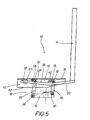
- Training according to Figures 5 and 6 differs from the embodiments of the seat 10 described above in that on the seat plate 12 from the longitudinal side walls 42 laterally wegumble guide members 50 are pivotally mounted, through which the front ends 38 of the rod members 36 of the second connecting means 20 for the backrest 14 extend linearly therethrough ,
- the guide members 50 may be formed, for example, as cylinders, as balls or the like with transversely oriented through holes for the rod members 36.
- FIGS. 7 and 8th illustrate an education of the seat 10 similar to that in the FIGS. 1 and 2 illustrated embodiment, wherein the seat 10 is formed with a weight adjusting 52.
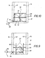
- a corresponding design of the weight adjusting device is in FIG. 10 schematically illustrates, which is a view in the direction of arrow X in FIG. 7 is.
- the front-side connecting levers 22 are each formed with an istwinkeiten extension 54 as a toggle lever, wherein the respective axis 28 is provided in the knee region of the corresponding knee lever.
- the two angled extensions 54 are connected together by means of a connecting rod 56, which forms a component of the weight adjusting device 52.
- FIG. 9 schematically illustrates an embodiment of the weight adjusting device 52 having an elastically resilient wedge member 58 which cooperates with the connecting rod 56.
- the wedge element 58 is guided linearly movably along two guide elements 60.
- the guide elements 60 are from the bottom 62 of the trough-like seat plate 12 upwards.
- a pivoting about an axis 64 adjustment handle 66 is connected to the wedge member 58 to bring the wedge member 58 along the guide members 60 with the connecting rod 56 more or less in operative connection.
- the wedge member 58 is drawn in an end position in which the compressibility of the wedge member 58 is comparatively small, so that a corresponding seat hardness is achieved.
- FIG. 10 an embodiment of the weight adjuster 52, which has a dimensionally stable wedge member 68 which is fixed to the connecting rod 56, and a cuboid body 70 made of elastically yielding material, along the bottom 62 of trough-like seat plate 12 upwardly extending guide elements 72 is guided linearly movable.
- an adjustment handle 66 which is pivotable about an axis 64.
- the axis 64 is provided on one of the two lateral, mutually remote longitudinal edges 74.
- the longitudinal edges 74 are of the longitudinal side walls 42 of the trough-like seat plate 12 materalein Glance away.
Landscapes
- Health & Medical Sciences (AREA)
- Dentistry (AREA)
- General Health & Medical Sciences (AREA)
- Chairs Characterized By Structure (AREA)
- Chairs For Special Purposes, Such As Reclining Chairs (AREA)
- Pharmaceuticals Containing Other Organic And Inorganic Compounds (AREA)
- Seats For Vehicles (AREA)
Claims (12)
- Siège comportant une plaque d'assise (12) et un dossier (14), ladite plaque d'assise (12) étant reliée au moyen d'un premier dispositif d'assemblage (18) à un dispositif de base (16) et étant réglable par rapport au dispositif de base (16) en hauteur et simultanément en inclinaison et dans le sens longitudinal du siège, ledit dossier (14) étant relié au moyen d'un deuxième dispositif d'assemblage (20) à la plaque d'assise (12) et étant réglable, simultanément avec la plaque d'assise (12), dans le sens longitudinal du siège en inclinaison et en hauteur,
le premier dispositif d'assemblage (18) comportant latéralement face à face une paire de leviers d'assemblage avant (22) et une paire de leviers d'assemblage arrière (24), les leviers d'assemblage avant (22) étant plus longs que les leviers d'assemblage arrière (24), et lesdits leviers d'assemblage arrière (24) étant réalisés sous la forme de leviers coudés, chacun avec un prolongement coudé (34),
caractérisé en ce que le deuxième dispositif d'assemblage (20) comporte latéralement face à face une paire de tiges (36), qui sont attachées par leur extrémité avant (38) à la plaque d'assise (12) de manière pivotante et mobile linéairement, et qui sont assemblées de manière pivotante avec le prolongement coudé (34) des leviers d'assemblage arrière (24). - Siège selon la revendication 1, caractérisé en ce que la plaque d'assise (12) est réalisée avec des trous oblongs (44), et en ce qu'au niveau de l'extrémité avant (38) de la tige (36) respective est prévu un élément de guidage (46) guidé dans le trou oblong (44) associé.
- Siège selon la revendication 1, caractérisé en ce que sur la plaque d'assise (12) sont prévus des manchons de guidage (48) aptes à pivoter, à l'intérieur desquels s'étend de manière mobile linéairement l'extrémité avant (38) de la tige (36) respective.
- Siège selon la revendication 1, caractérisé en ce que sur la plaque d'assise (12) sont prévus des organes de guidage (50) aptes à pivoter, à travers lesquels s'étend de manière mobile linéairement l'extrémité avant (38) des tiges (36).
- Siège selon l'une quelconque des revendications 1 à 4, caractérisé en ce que les leviers d'assemblage avant (22) sont réalisés chacun avec un prolongement coudé (54), lesdits prolongements coudés étant reliés entre eux au moyen d'une tige de liaison (56) prévue pour un dispositif de réglage du poids (52).
- Siège selon la revendication 5, caractérisé en ce que le dispositif de réglage du poids (52) comporte un élément de serrage (58) élastiquement flexible, qui est apte à être déplacé par rapport à la tige de liaison (56).
- Siège selon la revendication 5, caractérisé en ce que le dispositif de réglage du poids (52) comporte un élément de serrage (68) à forme stable, qui est fixé sur la tige de liaison (56), et un corps (70) en matériau élastiquement flexible, qui est apte à être déplacé par rapport à l'élément de serrage (68).
- Siège selon l'une quelconque des revendications 1 à 7, caractérisé en ce que la plaque d'assise (12) est réalisée en forme de cuve avec deux parois latérales longitudinales (42) et des bords longitudinaux (74), en saillie latéralement sur le dessus de celles-ci et en étant détournés l'un de l'autre.
- Siège selon la revendication 8, caractérisé en ce que les parois latérales longitudinales (42) sont réalisées avec des évidements pour la tige de liaison (56).
- Siège selon l'une quelconque des revendications 1 à 9, caractérisé en ce que le dispositif de base (16) est prévu pour le montage sur un élément formant un pied de chaise.
- Siège selon la revendication 10, caractérisé en ce que l'élément formant un pied de chaise est réglable en longueur.
- Siège selon la revendication 10 ou 11, caractérisé en ce que l'élément formant un pied de chaise comporte un dispositif d'amortissement.
Applications Claiming Priority (2)
| Application Number | Priority Date | Filing Date | Title |
|---|---|---|---|
| DE102006056928A DE102006056928B3 (de) | 2006-12-04 | 2006-12-04 | Sitz mit einer Sitzplatte und einer Rückenlehne |
| PCT/EP2007/010352 WO2008067947A1 (fr) | 2006-12-04 | 2007-11-29 | Siège avec une plaque d'assise et un dossier |
Publications (2)
| Publication Number | Publication Date |
|---|---|
| EP1993403A1 EP1993403A1 (fr) | 2008-11-26 |
| EP1993403B1 true EP1993403B1 (fr) | 2010-03-03 |
Family
ID=39182987
Family Applications (1)
| Application Number | Title | Priority Date | Filing Date |
|---|---|---|---|
| EP07846877A Active EP1993403B1 (fr) | 2006-12-04 | 2007-11-29 | Siège avec une plaque d'assise et un dossier |
Country Status (7)
| Country | Link |
|---|---|
| US (1) | US8215710B2 (fr) |
| EP (1) | EP1993403B1 (fr) |
| CN (1) | CN101573060B (fr) |
| AT (1) | ATE459265T1 (fr) |
| CA (1) | CA2671103C (fr) |
| DE (3) | DE202006018268U1 (fr) |
| WO (1) | WO2008067947A1 (fr) |
Families Citing this family (31)
| Publication number | Priority date | Publication date | Assignee | Title |
|---|---|---|---|---|
| CA2895942A1 (fr) | 2007-03-13 | 2008-09-13 | Hni Technologies Inc. | Systeme dynamique de support lombaire pour dossier |
| US8646839B2 (en) | 2008-06-17 | 2014-02-11 | Co.Fe.Mo. Industrie S.R.L. | Adjustment device for chairs |
| DE102009016968B4 (de) | 2009-04-14 | 2012-01-26 | Votteler Designpartner Gmbh | Sitzmöbel |
| WO2011104735A1 (fr) | 2010-02-26 | 2011-09-01 | Donati S.P.A. | Dispositif pour la synchronisation du siège et du dossier d'une chaise |
| AU2011250605B2 (en) | 2010-05-05 | 2016-06-16 | Allsteel Inc. | Moveable and demountable wall panel system for butt-glazed wall panels |
| TWM390712U (en) * | 2010-05-31 | 2010-10-21 | Wen-Shan Ke | Chair adjustment device |
| WO2012048863A1 (fr) * | 2010-10-15 | 2012-04-19 | Bock 1 Gmbh & Co. Kg | Mécanisme synchrone |
| ES2636488T3 (es) * | 2012-09-05 | 2017-10-05 | Godrej & Boyce Mfg Co Ltd | Silla con respaldo y asiento ajustables |
| CN102846068B (zh) * | 2012-09-18 | 2015-03-04 | 浙江永艺家具股份有限公司 | 一种转椅底盘 |
| DE202012011780U1 (de) | 2012-12-08 | 2013-01-18 | Nowy Styl Gmbh | Sitz |
| US9332851B2 (en) | 2013-03-15 | 2016-05-10 | Hni Technologies Inc. | Chair with activated back flex |
| JP6237468B2 (ja) * | 2013-06-10 | 2017-11-29 | トヨタ紡織株式会社 | 乗物用シート |
| CN106455824A (zh) | 2014-04-17 | 2017-02-22 | Hni技术公司 | 弯曲腰部支撑件 |
| USD731833S1 (en) | 2014-04-17 | 2015-06-16 | Allsteel Inc. | Chair |
| WO2015161281A1 (fr) | 2014-04-17 | 2015-10-22 | Hni Technologies Inc. | Chaise et ensembles, systèmes et procédés de commande de chaise |
| USD743180S1 (en) | 2014-10-15 | 2015-11-17 | Hni Technologies Inc. | Chair |
| US9801470B2 (en) | 2014-10-15 | 2017-10-31 | Hni Technologies Inc. | Molded chair with integrated support and method of making same |
| WO2016131485A1 (fr) * | 2015-02-19 | 2016-08-25 | Simon Desanta | Siège |
| US10194750B2 (en) | 2015-04-13 | 2019-02-05 | Steelcase Inc. | Seating arrangement |
| EP3282899B1 (fr) | 2015-04-13 | 2021-11-03 | Steelcase Inc. | Agencement de siège |
| US10966527B2 (en) | 2017-06-09 | 2021-04-06 | Steelcase Inc. | Seating arrangement and method of construction |
| US11259637B2 (en) | 2015-04-13 | 2022-03-01 | Steelcase Inc. | Seating arrangement |
| US9713381B2 (en) * | 2015-06-11 | 2017-07-25 | Davis Furniture Industries, Inc. | Chair |
| DE102015111946A1 (de) * | 2015-07-22 | 2017-01-26 | Bock 1 Gmbh & Co. Kg | Mechanik für einen Bürostuhl |
| JP6668947B2 (ja) * | 2016-05-26 | 2020-03-18 | トヨタ紡織株式会社 | 乗物用シート |
| GB2553750B (en) * | 2016-06-28 | 2019-06-05 | Posturite Ltd | Seat tilting mechanism |
| DE202018103213U1 (de) * | 2018-06-08 | 2019-09-11 | Armin Sander | Sitzmöbel |
| DE102018124512B4 (de) * | 2018-10-04 | 2020-09-03 | Grammer Ag | Fahrzeugsitz |
| US11109683B2 (en) | 2019-02-21 | 2021-09-07 | Steelcase Inc. | Body support assembly and method for the use and assembly thereof |
| US11357329B2 (en) | 2019-12-13 | 2022-06-14 | Steelcase Inc. | Body support assembly and methods for the use and assembly thereof |
| US11197548B2 (en) * | 2019-12-16 | 2021-12-14 | Allseating Corporation | Reclining control system for a chair |
Family Cites Families (28)
| Publication number | Priority date | Publication date | Assignee | Title |
|---|---|---|---|---|
| US2321385A (en) * | 1941-06-16 | 1943-06-08 | Sikes Company | Tilting chair |
| US3941417A (en) * | 1972-11-16 | 1976-03-02 | Dual Manufacturing And Engineering Incorporated | Reclining chair |
| CH645795A5 (en) * | 1979-07-23 | 1984-10-31 | Drabert Soehne | Chair, in particular visual display unit chair |
| DE3018686A1 (de) * | 1980-05-16 | 1981-11-26 | Ritter Ag, 7500 Karlsruhe | Zahnaerztlicher patientenstuhl |
| DE3139448C2 (de) * | 1981-10-03 | 1984-06-07 | Kusch & Co Sitzmöbelwerke KG, 5789 Hallenberg | Stuhl |
| JPS60117742U (ja) * | 1984-01-18 | 1985-08-09 | 株式会社岡村製作所 | 椅子のリクライニング装置 |
| GB8432094D0 (en) * | 1984-12-19 | 1985-01-30 | Flight Equipment & Eng Ltd | Reclinable vehicle seats |
| DE8515221U1 (de) * | 1985-05-23 | 1986-05-22 | VOKO - Franz Vogt & Co, 6301 Pohlheim | Sitzmöbel |
| DE3617624A1 (de) | 1986-05-26 | 1987-12-03 | Drabert Soehne | Stuhl |
| US4740031A (en) * | 1986-09-05 | 1988-04-26 | Parma Corporation | Mechanism for a reclining chair or sofa module |
| NL8602506A (nl) * | 1986-10-06 | 1988-05-02 | Ahrend Groep Nv | Stoel met beweegbare zitting en rugleuning. |
| WO1989003649A1 (fr) * | 1987-10-24 | 1989-05-05 | Kokuyo Co., Ltd. | Chaise basculante |
| DK167334B1 (da) * | 1990-01-10 | 1993-10-18 | Space International Aps | Konvertibel stol |
| US5464274A (en) * | 1994-01-13 | 1995-11-07 | Westinghouse Electric Corporation | Chair seat tilt adjustment and locking mechanism |
| US5782536A (en) * | 1995-02-17 | 1998-07-21 | Steelcase Inc. | Modular chair construction and method of assembly |
| DE19646470B4 (de) * | 1996-11-11 | 2005-06-09 | C. Rob. Hammerstein Gmbh & Co. Kg | Kraftfahrzeugsitz mit einer Lehne und einem Sitz |
| US6139103A (en) * | 1997-03-12 | 2000-10-31 | Leggett & Platt, Inc. | Synchronized chair seat and backrest tilt control mechanism |
| US5909924A (en) * | 1997-04-30 | 1999-06-08 | Haworth, Inc. | Tilt control for chair |
| US6709058B1 (en) * | 1999-04-09 | 2004-03-23 | Humanscale Corp. | Ergonomic chair |
| AU2001245735A1 (en) * | 2000-03-17 | 2001-10-03 | Herman Miller, Inc. | Tilt assembly for a chair |
| US6729688B2 (en) * | 2000-03-24 | 2004-05-04 | Giroflex-Entwicklungs-Ag | Seat and backseat assembly for seating, in particular office chairs |
| IT1320421B1 (it) * | 2000-06-09 | 2003-11-26 | Pro Cord Srl | Sedia con sedile e schienale oscillanti in modo sincronizzato. |
| GB0024840D0 (en) * | 2000-10-10 | 2000-11-22 | Rodd Engineering Ltd | Chair tilting mechanism and a chair incorporating such a mechanism |
| DE10122945A1 (de) * | 2001-05-11 | 2002-12-12 | Armin Sander | Stuhl, insbesondere Bürostuhl |
| US7165811B2 (en) * | 2002-09-12 | 2007-01-23 | Steelcase Development Corporation | Control mechanism for seating unit |
| JP4477011B2 (ja) * | 2003-05-23 | 2010-06-09 | マンプラス カンパニー リミテッド | 背受けを自動的に移動調節する椅子 |
| DE102005009419A1 (de) * | 2005-03-02 | 2006-09-07 | Recaro Aircraft Seating Gmbh & Co. Kg | Sitz |
| US7837265B2 (en) * | 2006-03-24 | 2010-11-23 | Hni Corporation | Reclining chair with enhanced adjustability |
-
2006
- 2006-12-04 DE DE202006018268U patent/DE202006018268U1/de not_active Expired - Lifetime
- 2006-12-04 DE DE102006056928A patent/DE102006056928B3/de not_active Expired - Fee Related
-
2007
- 2007-11-29 AT AT07846877T patent/ATE459265T1/de active
- 2007-11-29 CN CN200780049249.XA patent/CN101573060B/zh active Active
- 2007-11-29 EP EP07846877A patent/EP1993403B1/fr active Active
- 2007-11-29 DE DE502007003003T patent/DE502007003003D1/de active Active
- 2007-11-29 CA CA2671103A patent/CA2671103C/fr active Active
- 2007-11-29 WO PCT/EP2007/010352 patent/WO2008067947A1/fr active Application Filing
- 2007-11-29 US US12/517,401 patent/US8215710B2/en active Active
Also Published As
| Publication number | Publication date |
|---|---|
| EP1993403A1 (fr) | 2008-11-26 |
| US8215710B2 (en) | 2012-07-10 |
| CN101573060A (zh) | 2009-11-04 |
| CN101573060B (zh) | 2011-09-28 |
| WO2008067947A1 (fr) | 2008-06-12 |
| CA2671103C (fr) | 2014-08-19 |
| ATE459265T1 (de) | 2010-03-15 |
| US20100084904A1 (en) | 2010-04-08 |
| CA2671103A1 (fr) | 2008-06-12 |
| DE202006018268U1 (de) | 2007-02-08 |
| DE502007003003D1 (de) | 2010-04-15 |
| DE102006056928B3 (de) | 2008-06-05 |
Similar Documents
| Publication | Publication Date | Title |
|---|---|---|
| EP1993403B1 (fr) | Siège avec une plaque d'assise et un dossier | |
| DE19646470B4 (de) | Kraftfahrzeugsitz mit einer Lehne und einem Sitz | |
| DE102008030608B4 (de) | Sitztiefenverstellbarer Kraftfahrzeugsitz | |
| EP2243398B1 (fr) | Meubles destinés à s'asseoir | |
| DE102005017634B4 (de) | Fahrzeugsitz mit verformbarer S-förmiger Rückenlehne | |
| AT12867U1 (de) | Sitzmöbel | |
| DE102005005345A1 (de) | Sitzanordnung | |
| DE4104409C2 (de) | Sitz, insbes. Fahrzeugsitz | |
| EP2047769B1 (fr) | Siège de personnes à suspension | |
| EP2548763B1 (fr) | Siège de véhicule doté d'une déformation de dossier | |
| EP3254887B1 (fr) | Siège de véhicule présentant une combinaison de possibilités de réglage | |
| DE102009043298B4 (de) | Fahrzeugsitz mit erhöhtem Sitzkomfort | |
| DE3243747A1 (de) | Sitz mit in ihrer neigung verstellbarer sitzflaeche | |
| DE102007060327A1 (de) | Horizontal verstellbare Armlehne | |
| DE10206223B4 (de) | Scherengestell für einen Sitz | |
| EP3345507A1 (fr) | Mécanisme pour une chaise | |
| DE4236834C2 (de) | Sitzmöbel | |
| DE19701387C2 (de) | Fahrzeugsitz | |
| DE102007003642A1 (de) | Rückenlehne für einen Fahrzeugsitz | |
| DE102005035947A1 (de) | Fahrzeugsitz mit einer verformbaren Rückenlehne | |
| EP0347538A1 (fr) | Chaise, notamment chaise de bureau | |
| DE102019113581A1 (de) | Synchronmechanik | |
| DE102006056547B3 (de) | Stuhl | |
| DE19938485C2 (de) | Stuhl | |
| DE102015103644A1 (de) | Fahrzeugsitz mit wippenartigem Element in der Rückenlehne |
Legal Events
| Date | Code | Title | Description |
|---|---|---|---|
| PUAI | Public reference made under article 153(3) epc to a published international application that has entered the european phase |
Free format text: ORIGINAL CODE: 0009012 |
|
| 17P | Request for examination filed |
Effective date: 20081008 |
|
| AK | Designated contracting states |
Kind code of ref document: A1 Designated state(s): AT BE BG CH CY CZ DE DK EE ES FI FR GB GR HU IE IS IT LI LT LU LV MC MT NL PL PT RO SE SI SK TR |
|
| AX | Request for extension of the european patent |
Extension state: AL BA HR MK RS |
|
| GRAP | Despatch of communication of intention to grant a patent |
Free format text: ORIGINAL CODE: EPIDOSNIGR1 |
|
| GRAJ | Information related to disapproval of communication of intention to grant by the applicant or resumption of examination proceedings by the epo deleted |
Free format text: ORIGINAL CODE: EPIDOSDIGR1 |
|
| GRAP | Despatch of communication of intention to grant a patent |
Free format text: ORIGINAL CODE: EPIDOSNIGR1 |
|
| RIN1 | Information on inventor provided before grant (corrected) |
Inventor name: ERKER, CHRISTIAN |
|
| GRAS | Grant fee paid |
Free format text: ORIGINAL CODE: EPIDOSNIGR3 |
|
| GRAA | (expected) grant |
Free format text: ORIGINAL CODE: 0009210 |
|
| AK | Designated contracting states |
Kind code of ref document: B1 Designated state(s): AT BE BG CH CY CZ DE DK EE ES FI FR GB GR HU IE IS IT LI LT LU LV MC MT NL PL PT RO SE SI SK TR |
|
| REG | Reference to a national code |
Ref country code: GB Ref legal event code: FG4D Free format text: NOT ENGLISH |
|
| REG | Reference to a national code |
Ref country code: CH Ref legal event code: EP |
|
| REG | Reference to a national code |
Ref country code: IE Ref legal event code: FG4D |
|
| REF | Corresponds to: |
Ref document number: 502007003003 Country of ref document: DE Date of ref document: 20100415 Kind code of ref document: P |
|
| REG | Reference to a national code |
Ref country code: NL Ref legal event code: VDEP Effective date: 20100303 |
|
| PG25 | Lapsed in a contracting state [announced via postgrant information from national office to epo] |
Ref country code: LT Free format text: LAPSE BECAUSE OF FAILURE TO SUBMIT A TRANSLATION OF THE DESCRIPTION OR TO PAY THE FEE WITHIN THE PRESCRIBED TIME-LIMIT Effective date: 20100303 |
|
| LTIE | Lt: invalidation of european patent or patent extension |
Effective date: 20100303 |
|
| PG25 | Lapsed in a contracting state [announced via postgrant information from national office to epo] |
Ref country code: FI Free format text: LAPSE BECAUSE OF FAILURE TO SUBMIT A TRANSLATION OF THE DESCRIPTION OR TO PAY THE FEE WITHIN THE PRESCRIBED TIME-LIMIT Effective date: 20100303 Ref country code: LV Free format text: LAPSE BECAUSE OF FAILURE TO SUBMIT A TRANSLATION OF THE DESCRIPTION OR TO PAY THE FEE WITHIN THE PRESCRIBED TIME-LIMIT Effective date: 20100303 Ref country code: PL Free format text: LAPSE BECAUSE OF FAILURE TO SUBMIT A TRANSLATION OF THE DESCRIPTION OR TO PAY THE FEE WITHIN THE PRESCRIBED TIME-LIMIT Effective date: 20100303 Ref country code: SI Free format text: LAPSE BECAUSE OF FAILURE TO SUBMIT A TRANSLATION OF THE DESCRIPTION OR TO PAY THE FEE WITHIN THE PRESCRIBED TIME-LIMIT Effective date: 20100303 |
|
| REG | Reference to a national code |
Ref country code: IE Ref legal event code: FD4D |
|
| PG25 | Lapsed in a contracting state [announced via postgrant information from national office to epo] |
Ref country code: EE Free format text: LAPSE BECAUSE OF FAILURE TO SUBMIT A TRANSLATION OF THE DESCRIPTION OR TO PAY THE FEE WITHIN THE PRESCRIBED TIME-LIMIT Effective date: 20100303 Ref country code: SE Free format text: LAPSE BECAUSE OF FAILURE TO SUBMIT A TRANSLATION OF THE DESCRIPTION OR TO PAY THE FEE WITHIN THE PRESCRIBED TIME-LIMIT Effective date: 20100303 Ref country code: RO Free format text: LAPSE BECAUSE OF FAILURE TO SUBMIT A TRANSLATION OF THE DESCRIPTION OR TO PAY THE FEE WITHIN THE PRESCRIBED TIME-LIMIT Effective date: 20100303 Ref country code: CY Free format text: LAPSE BECAUSE OF FAILURE TO SUBMIT A TRANSLATION OF THE DESCRIPTION OR TO PAY THE FEE WITHIN THE PRESCRIBED TIME-LIMIT Effective date: 20100303 Ref country code: GR Free format text: LAPSE BECAUSE OF FAILURE TO SUBMIT A TRANSLATION OF THE DESCRIPTION OR TO PAY THE FEE WITHIN THE PRESCRIBED TIME-LIMIT Effective date: 20100604 Ref country code: IE Free format text: LAPSE BECAUSE OF FAILURE TO SUBMIT A TRANSLATION OF THE DESCRIPTION OR TO PAY THE FEE WITHIN THE PRESCRIBED TIME-LIMIT Effective date: 20100303 Ref country code: ES Free format text: LAPSE BECAUSE OF FAILURE TO SUBMIT A TRANSLATION OF THE DESCRIPTION OR TO PAY THE FEE WITHIN THE PRESCRIBED TIME-LIMIT Effective date: 20100614 Ref country code: NL Free format text: LAPSE BECAUSE OF FAILURE TO SUBMIT A TRANSLATION OF THE DESCRIPTION OR TO PAY THE FEE WITHIN THE PRESCRIBED TIME-LIMIT Effective date: 20100303 |
|
| PG25 | Lapsed in a contracting state [announced via postgrant information from national office to epo] |
Ref country code: BG Free format text: LAPSE BECAUSE OF FAILURE TO SUBMIT A TRANSLATION OF THE DESCRIPTION OR TO PAY THE FEE WITHIN THE PRESCRIBED TIME-LIMIT Effective date: 20100603 Ref country code: CZ Free format text: LAPSE BECAUSE OF FAILURE TO SUBMIT A TRANSLATION OF THE DESCRIPTION OR TO PAY THE FEE WITHIN THE PRESCRIBED TIME-LIMIT Effective date: 20100303 Ref country code: IS Free format text: LAPSE BECAUSE OF FAILURE TO SUBMIT A TRANSLATION OF THE DESCRIPTION OR TO PAY THE FEE WITHIN THE PRESCRIBED TIME-LIMIT Effective date: 20100703 Ref country code: SK Free format text: LAPSE BECAUSE OF FAILURE TO SUBMIT A TRANSLATION OF THE DESCRIPTION OR TO PAY THE FEE WITHIN THE PRESCRIBED TIME-LIMIT Effective date: 20100303 |
|
| PLBE | No opposition filed within time limit |
Free format text: ORIGINAL CODE: 0009261 |
|
| STAA | Information on the status of an ep patent application or granted ep patent |
Free format text: STATUS: NO OPPOSITION FILED WITHIN TIME LIMIT |
|
| PG25 | Lapsed in a contracting state [announced via postgrant information from national office to epo] |
Ref country code: DK Free format text: LAPSE BECAUSE OF FAILURE TO SUBMIT A TRANSLATION OF THE DESCRIPTION OR TO PAY THE FEE WITHIN THE PRESCRIBED TIME-LIMIT Effective date: 20100303 Ref country code: PT Free format text: LAPSE BECAUSE OF FAILURE TO SUBMIT A TRANSLATION OF THE DESCRIPTION OR TO PAY THE FEE WITHIN THE PRESCRIBED TIME-LIMIT Effective date: 20100705 |
|
| 26N | No opposition filed |
Effective date: 20101206 |
|
| BERE | Be: lapsed |
Owner name: SATO-OFFICE G.M.B.H. Effective date: 20101130 |
|
| PG25 | Lapsed in a contracting state [announced via postgrant information from national office to epo] |
Ref country code: MC Free format text: LAPSE BECAUSE OF NON-PAYMENT OF DUE FEES Effective date: 20101130 |
|
| PG25 | Lapsed in a contracting state [announced via postgrant information from national office to epo] |
Ref country code: BE Free format text: LAPSE BECAUSE OF NON-PAYMENT OF DUE FEES Effective date: 20101130 |
|
| PG25 | Lapsed in a contracting state [announced via postgrant information from national office to epo] |
Ref country code: MT Free format text: LAPSE BECAUSE OF FAILURE TO SUBMIT A TRANSLATION OF THE DESCRIPTION OR TO PAY THE FEE WITHIN THE PRESCRIBED TIME-LIMIT Effective date: 20100303 Ref country code: IT Free format text: LAPSE BECAUSE OF NON-PAYMENT OF DUE FEES Effective date: 20101129 |
|
| REG | Reference to a national code |
Ref country code: CH Ref legal event code: PL |
|
| PG25 | Lapsed in a contracting state [announced via postgrant information from national office to epo] |
Ref country code: LI Free format text: LAPSE BECAUSE OF NON-PAYMENT OF DUE FEES Effective date: 20111130 Ref country code: CH Free format text: LAPSE BECAUSE OF NON-PAYMENT OF DUE FEES Effective date: 20111130 |
|
| PG25 | Lapsed in a contracting state [announced via postgrant information from national office to epo] |
Ref country code: LU Free format text: LAPSE BECAUSE OF NON-PAYMENT OF DUE FEES Effective date: 20101129 Ref country code: HU Free format text: LAPSE BECAUSE OF FAILURE TO SUBMIT A TRANSLATION OF THE DESCRIPTION OR TO PAY THE FEE WITHIN THE PRESCRIBED TIME-LIMIT Effective date: 20100904 |
|
| PG25 | Lapsed in a contracting state [announced via postgrant information from national office to epo] |
Ref country code: TR Free format text: LAPSE BECAUSE OF FAILURE TO SUBMIT A TRANSLATION OF THE DESCRIPTION OR TO PAY THE FEE WITHIN THE PRESCRIBED TIME-LIMIT Effective date: 20100303 |
|
| REG | Reference to a national code |
Ref country code: DE Ref legal event code: R082 Ref document number: 502007003003 Country of ref document: DE Representative=s name: LOUIS, POEHLAU, LOHRENTZ, DE |
|
| REG | Reference to a national code |
Ref country code: DE Ref legal event code: R082 Ref document number: 502007003003 Country of ref document: DE Representative=s name: LOUIS, POEHLAU, LOHRENTZ, DE Effective date: 20121212 Ref country code: DE Ref legal event code: R081 Ref document number: 502007003003 Country of ref document: DE Owner name: NOWY STYL GMBH, DE Free format text: FORMER OWNER: SATO OFFICE GMBH, 92263 EBERMANNSDORF, DE Effective date: 20121212 |
|
| REG | Reference to a national code |
Ref country code: AT Ref legal event code: MM01 Ref document number: 459265 Country of ref document: AT Kind code of ref document: T Effective date: 20121130 |
|
| PG25 | Lapsed in a contracting state [announced via postgrant information from national office to epo] |
Ref country code: AT Free format text: LAPSE BECAUSE OF NON-PAYMENT OF DUE FEES Effective date: 20121130 |
|
| REG | Reference to a national code |
Ref country code: FR Ref legal event code: PLFP Year of fee payment: 9 |
|
| REG | Reference to a national code |
Ref country code: FR Ref legal event code: PLFP Year of fee payment: 10 |
|
| REG | Reference to a national code |
Ref country code: FR Ref legal event code: PLFP Year of fee payment: 11 |
|
| REG | Reference to a national code |
Ref country code: DE Ref legal event code: R081 Ref document number: 502007003003 Country of ref document: DE Owner name: NOWY STYL SP. Z O.O., PL Free format text: FORMER OWNER: NOWY STYL GMBH, 92263 EBERMANNSDORF, DE |
|
| PGFP | Annual fee paid to national office [announced via postgrant information from national office to epo] |
Ref country code: GB Payment date: 20231123 Year of fee payment: 17 |
|
| PGFP | Annual fee paid to national office [announced via postgrant information from national office to epo] |
Ref country code: IT Payment date: 20231130 Year of fee payment: 17 Ref country code: FR Payment date: 20231124 Year of fee payment: 17 Ref country code: DE Payment date: 20231103 Year of fee payment: 17 |