EP1993403B1 - Seat having a seat panel and a backrest - Google Patents
Seat having a seat panel and a backrest Download PDFInfo
- Publication number
- EP1993403B1 EP1993403B1 EP07846877A EP07846877A EP1993403B1 EP 1993403 B1 EP1993403 B1 EP 1993403B1 EP 07846877 A EP07846877 A EP 07846877A EP 07846877 A EP07846877 A EP 07846877A EP 1993403 B1 EP1993403 B1 EP 1993403B1
- Authority
- EP
- European Patent Office
- Prior art keywords
- seat
- seat according
- levers
- panel
- rod
- Prior art date
- Legal status (The legal status is an assumption and is not a legal conclusion. Google has not performed a legal analysis and makes no representation as to the accuracy of the status listed.)
- Active
Links
- 238000013016 damping Methods 0.000 claims description 2
- 239000000463 material Substances 0.000 claims description 2
- 210000003127 knee Anatomy 0.000 description 3
- TVEXGJYMHHTVKP-UHFFFAOYSA-N 6-oxabicyclo[3.2.1]oct-3-en-7-one Chemical compound C1C2C(=O)OC1C=CC2 TVEXGJYMHHTVKP-UHFFFAOYSA-N 0.000 description 1
- 238000000605 extraction Methods 0.000 description 1
- 239000012858 resilient material Substances 0.000 description 1
Images


Classifications
-
- A—HUMAN NECESSITIES
- A47—FURNITURE; DOMESTIC ARTICLES OR APPLIANCES; COFFEE MILLS; SPICE MILLS; SUCTION CLEANERS IN GENERAL
- A47C—CHAIRS; SOFAS; BEDS
- A47C1/00—Chairs adapted for special purposes
- A47C1/02—Reclining or easy chairs
- A47C1/031—Reclining or easy chairs having coupled concurrently adjustable supporting parts
- A47C1/032—Reclining or easy chairs having coupled concurrently adjustable supporting parts the parts being movably-coupled seat and back-rest
- A47C1/03255—Reclining or easy chairs having coupled concurrently adjustable supporting parts the parts being movably-coupled seat and back-rest with a central column, e.g. rocking office chairs
-
- A—HUMAN NECESSITIES
- A47—FURNITURE; DOMESTIC ARTICLES OR APPLIANCES; COFFEE MILLS; SPICE MILLS; SUCTION CLEANERS IN GENERAL
- A47C—CHAIRS; SOFAS; BEDS
- A47C1/00—Chairs adapted for special purposes
- A47C1/02—Reclining or easy chairs
- A47C1/031—Reclining or easy chairs having coupled concurrently adjustable supporting parts
- A47C1/032—Reclining or easy chairs having coupled concurrently adjustable supporting parts the parts being movably-coupled seat and back-rest
- A47C1/03261—Reclining or easy chairs having coupled concurrently adjustable supporting parts the parts being movably-coupled seat and back-rest characterised by elastic means
- A47C1/03288—Reclining or easy chairs having coupled concurrently adjustable supporting parts the parts being movably-coupled seat and back-rest characterised by elastic means with resilient blocks
-
- A—HUMAN NECESSITIES
- A47—FURNITURE; DOMESTIC ARTICLES OR APPLIANCES; COFFEE MILLS; SPICE MILLS; SUCTION CLEANERS IN GENERAL
- A47C—CHAIRS; SOFAS; BEDS
- A47C1/00—Chairs adapted for special purposes
- A47C1/02—Reclining or easy chairs
- A47C1/031—Reclining or easy chairs having coupled concurrently adjustable supporting parts
- A47C1/032—Reclining or easy chairs having coupled concurrently adjustable supporting parts the parts being movably-coupled seat and back-rest
- A47C1/03294—Reclining or easy chairs having coupled concurrently adjustable supporting parts the parts being movably-coupled seat and back-rest slidingly movable in the base frame, e.g. by rollers
Definitions
- the invention relates to a seat with a seat plate and a backrest, wherein the seat plate is connected to a first connecting means with a base means and adjustable relative to the base means in height and at the same time in the inclination and in the seat longitudinal direction, wherein the backrest by means of a second connecting means the seat plate is connected and simultaneously adjustable with the seat plate in the inclination and in the height, wherein the first connection means laterally opposite a pair of front side and a pair of rear side connecting lever, wherein the front kaushebei are longer than the rear side connecting lever, and wherein the back Connection lever are each formed with an angled extension as a toggle lever.
- Such a seat is eg off DE 30 27 311 known.
- the invention has for its object to realize such a seat structurally simple design with optimal seating comfort.
- connection means laterally opposite a pair of rod members which are pivotally and linearly mounted with its front end to the seat plate, and pivotally connected to the angled extension of the rear connecting lever are.
- the two laterally opposite front side connecting lever and the two laterally opposite rear connecting lever form between the base device and the seat plate quasi a parallelogram linkage, which is achieved by the dimensions of the front and the rear link that when pivoting the connecting lever the Seat plate relative to the base device is moved from an at least approximately horizontal position in the seat longitudinal direction to the front above and with its rear part down.
- the backrest is adjusted with its lower part forward and with its shoulder portion to the rear. In this way, a good seating comfort results, at the same time the so-called "shirt extraction effect" is prevented.
- the seat plate may be formed with oblong holes and may be provided at the front end of the respective rod member guided in the associated slot guide member. In this way, a pivotable and linearly movable mounting of the front ends of the two laterally opposite rod elements on the seat plate is possible.
- seat plate guide sleeves are pivotally provided, which are formed with a blind hole and in which the front end of the respective rod member extends linearly movable into it.
- These guide sleeves are formed, for example, as sliding shoes.
- pivotable and simultaneously linear mobility of the front end of the rod elements with respect to the seat plate is that on the seat plate guide members are provided pivotally through which the front end of the rod members extending linearly therethrough.
- These pivotable guide members may od as pins, balls.
- This connecting rod is advantageously provided for a weight adjusting device.
- This weight adjuster may comprise an elastically compliant wedge member that is adjustable with respect to the connecting rod.
- the weight adjuster comprises a dimensionally stable wedge member fixed to the connecting rod and a body of resilient material which is adjustable with respect to the wedge member.
- the seat plate is formed like a trough with two longitudinal side walls and from the upper side laterally facing away from each other wegappel longitudinal edges. In this way, a desired dimensional stability results, while at the same time it is possible to easily accommodate the above-mentioned weight adjustment.
- the longitudinal edges or the longitudinal side walls may be formed with recesses for the connecting rod connecting the front-side connecting levers.
- the base device may be provided on a chair pillar element.
- This column member may be adjustable in length to realize a height-adjustable chair.
- This chair is conveniently an office chair.
- the chair pillar member may include a damper.
- This damping device is, for example, a gas spring, as used in office chairs.
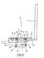
- FIGS. 1 and 2 show in a side view a first embodiment of the seat 10.
- the seat 10 has a seat plate 12 and a backrest 14.
- the seat plate 12 is connected to a base device 16 of the seat 10 by means of a first connecting device 18.
- the backrest 14 is connected to the seat plate 12 by means of a second connecting device 20.
- the first connecting device 18 has a pair of front side connecting levers 22 located laterally of the seat plate 12 and a pair of rear connecting levers 24 located laterally of the seat plate 12.
- the front link levers 22 are pivotally connected to the base 16 by means of axles 26 and to the seat plate 12 by means of axles 28.
- the rear linkage levers 24 are pivotally connected to the base 16 by means of axles 30 and to the seat plate 12 by means of axles 32.
- the front link levers 22 are longer between the axles 26 and 28 than the rear link levers 24 between the axles 30 and 32.
- the rear connecting levers 24 are each formed with an angled extension 34 as a toggle lever, wherein the axis 32 is provided in the knee region of the respective rear connecting lever 24.
- the provided for connecting the backrest 14 with the seat plate 12 second connecting device 20 has two laterally of the seat plate 12 opposite rod members 36 which are mounted with its front end 38 on the seat plate 12 pivotally and limited linearly movable.
- the Rod members 36 are also pivotally connected to the angled extension 34 of the rear link 24.
- the respective rod member 36 is connected to the associated angled extension 34 by means of an axle 40.
- the trough-like with two longitudinal side walls 42 formed seat plate 12 is formed on the longitudinal side walls 42 with slots 44.
- a guide member 46 is provided which extends into the associated slot 44 and is guided in this play.
- FIGS. 1 and 2 a second embodiment of the seat 10 is shown in the upright and in a backward obliquely inclined position.
- trained as sliding shoes guide sleeves 48 are provided on the seat plate 12 which are axially aligned pivotally away from the longitudinal side walls 42 of the seat plate 12 and in which the front ends 38 of the rod members 36 of the second connection means 20 for the backrest 14 extend linearly movable into it ,
- FIGS. 1 to 4 illustrate a third embodiment of the seat 10 in an upright and in a backward obliquely inclined position, wherein like details with the same reference numerals as in FIGS. 1 to 4 are designated.
- Training according to Figures 5 and 6 differs from the embodiments of the seat 10 described above in that on the seat plate 12 from the longitudinal side walls 42 laterally wegumble guide members 50 are pivotally mounted, through which the front ends 38 of the rod members 36 of the second connecting means 20 for the backrest 14 extend linearly therethrough ,
- the guide members 50 may be formed, for example, as cylinders, as balls or the like with transversely oriented through holes for the rod members 36.
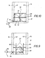
- FIGS. 7 and 8th illustrate an education of the seat 10 similar to that in the FIGS. 1 and 2 illustrated embodiment, wherein the seat 10 is formed with a weight adjusting 52.
- a corresponding design of the weight adjusting device is in FIG. 10 schematically illustrates, which is a view in the direction of arrow X in FIG. 7 is.
- the front-side connecting levers 22 are each formed with an istwinkeiten extension 54 as a toggle lever, wherein the respective axis 28 is provided in the knee region of the corresponding knee lever.
- the two angled extensions 54 are connected together by means of a connecting rod 56, which forms a component of the weight adjusting device 52.
- FIG. 9 schematically illustrates an embodiment of the weight adjusting device 52 having an elastically resilient wedge member 58 which cooperates with the connecting rod 56.
- the wedge element 58 is guided linearly movably along two guide elements 60.
- the guide elements 60 are from the bottom 62 of the trough-like seat plate 12 upwards.
- a pivoting about an axis 64 adjustment handle 66 is connected to the wedge member 58 to bring the wedge member 58 along the guide members 60 with the connecting rod 56 more or less in operative connection.
- the wedge member 58 is drawn in an end position in which the compressibility of the wedge member 58 is comparatively small, so that a corresponding seat hardness is achieved.
- FIG. 10 an embodiment of the weight adjuster 52, which has a dimensionally stable wedge member 68 which is fixed to the connecting rod 56, and a cuboid body 70 made of elastically yielding material, along the bottom 62 of trough-like seat plate 12 upwardly extending guide elements 72 is guided linearly movable.
- an adjustment handle 66 which is pivotable about an axis 64.
- the axis 64 is provided on one of the two lateral, mutually remote longitudinal edges 74.
- the longitudinal edges 74 are of the longitudinal side walls 42 of the trough-like seat plate 12 materalein Glance away.
Landscapes
- Health & Medical Sciences (AREA)
- Dentistry (AREA)
- General Health & Medical Sciences (AREA)
- Chairs For Special Purposes, Such As Reclining Chairs (AREA)
- Chairs Characterized By Structure (AREA)
- Pharmaceuticals Containing Other Organic And Inorganic Compounds (AREA)
- Seats For Vehicles (AREA)
Abstract
Description
Die Erfindung betrifft einen Sitz mit einer Sitzplatte und einer Rückenlehne, wobei die Sitzplatte mit einer ersten Verbindungseinrichtung mit einer Basiseinrichtung verbunden und in Bezug zur Basiseinrichtung in der Höhe und gleichzeitig in der Neigung und in Sitzlängsrichtung verstellbar ist, wobei die Rückenlehne mittels einer zweiten Verbindungseinrichtung mit der Sitzplatte verbunden und simultan mit der Sitzplatte in der Neigung und in der Höhe verstellbar ist, wobei die erste Verbindungseinrichtung seitlich gegenüber liegend ein Paar vorderseitige und ein Paar rückseitige Verbindungshebel aufweist, wobei die vorderseitigen Verbindungshebei länger sind als die rückseitigen Verbindungshebel, und wobei die rückseitigen Verbindungshebel jeweils mit einer abgewinkelten Verlängerung als Kniehebel ausgebildet sind.The invention relates to a seat with a seat plate and a backrest, wherein the seat plate is connected to a first connecting means with a base means and adjustable relative to the base means in height and at the same time in the inclination and in the seat longitudinal direction, wherein the backrest by means of a second connecting means the seat plate is connected and simultaneously adjustable with the seat plate in the inclination and in the height, wherein the first connection means laterally opposite a pair of front side and a pair of rear side connecting lever, wherein the front Verbindungshebei are longer than the rear side connecting lever, and wherein the back Connection lever are each formed with an angled extension as a toggle lever.
Ein solcher Sitz ist z.B. aus
Der Erfindung liegt die Aufgabe zugrunde, einen derartigen Sitz konstruktiv einfach gestaltet mit einem optimalen Sitzkomfort zu verwirklichen.The invention has for its object to realize such a seat structurally simple design with optimal seating comfort.
Diese Aufgabe wird bei einem Sitz der oben genannten Art erfindungsgemäss dadurch gelöst, dass die zweite Verbindungseinrichtung seitlich gegenüberliegend ein Paar Stangenelemente aufweist, die mit ihrem Vorderende an der Sitzplatte verschwenkbar und linear beweglich angebracht sind, und die mit der abgewinkelten Verlängerung der rückseitigen Verbindungshebel verschwenkbar verbunden sind.This object is achieved in a seat of the type mentioned above according to the invention that the second connection means laterally opposite a pair of rod members which are pivotally and linearly mounted with its front end to the seat plate, and pivotally connected to the angled extension of the rear connecting lever are.
Die beiden sich seitlich gegenüber liegenden vorderseitigen Verbindungshebel und die beiden sich seitlich gegenüber liegenden rückseitigen Verbindungshebel bilden zwischen der Basiseinrichtung und der Sitzplatte quasi ein Parallelogramm-Gestänge, wobei durch die Dimensionierungen der vorderseitigen und der rückseitigen Verbindungshebel erreicht wird, dass bei einer Verschwenkung der Verbindungshebel die Sitzplatte in Bezug zur Basiseinrichtung von einer mindestens annähernd horizontalen Stellung in Sitzlängsrichtung nach vorne oben und mit ihrem rückseitigen Teil nach unten verstellt wird. Gleichzeitig wird die Rückenlehne mit ihrem unteren Teil nach vorne und mit ihrem Schulterabschnitt nach hinten verstellt. Auf diese Weise ergibt sich ein guter Sitzkomfort, wobei gleichzeitig der sogenannte "Hemdauszieheffekt" verhindert wird.The two laterally opposite front side connecting lever and the two laterally opposite rear connecting lever form between the base device and the seat plate quasi a parallelogram linkage, which is achieved by the dimensions of the front and the rear link that when pivoting the connecting lever the Seat plate relative to the base device is moved from an at least approximately horizontal position in the seat longitudinal direction to the front above and with its rear part down. At the same time, the backrest is adjusted with its lower part forward and with its shoulder portion to the rear. In this way, a good seating comfort results, at the same time the so-called "shirt extraction effect" is prevented.
Bei dem erfindungsgemässen Sitz kann die Sitzplatte mit Langlöchern ausgebildet sein und kann am Vorderende des jeweiligen Stangenelementes ein im zugehörigen Langloch geführtes Führungselement vorgesehen sein. Auf diese Weise ist eine verschwenkbare und linear bewegliche Lagerung der Vorderenden der beiden sich seitlich gegenüber liegenden Stangenelemente an der Sitzplatte möglich.In the inventive seat, the seat plate may be formed with oblong holes and may be provided at the front end of the respective rod member guided in the associated slot guide member. In this way, a pivotable and linearly movable mounting of the front ends of the two laterally opposite rod elements on the seat plate is possible.
Eine andere Möglichkeit besteht darin, dass an der Sitzplatte Führungshülsen verschwenkbar vorgesehen sind, die mit einem Sackloch ausgebildet sind und in die sich das Vorderende des jeweiligen Stangenelementes linear beweglich hinein erstreckt. Diese Führungshülsen sind beispielsweise als Gleitschuhe ausgebildet.Another possibility is that on the seat plate guide sleeves are pivotally provided, which are formed with a blind hole and in which the front end of the respective rod member extends linearly movable into it. These guide sleeves are formed, for example, as sliding shoes.
Noch eine andere Möglichkeit der verschwenkbaren und gleichzeitig linearen Beweglichkeit des Vorderendes der Stangenelemente in Bezug zur Sitzplatte besteht darin, dass an der Sitzplatte Führungsorgane verschwenkbar vorgesehen sind, durch die sich das Vorderende der Stangenelemente linear beweglich hindurch erstreckt. Diese verschwenkbaren Führungsorgane können als Zapfen, Kugeln od. dgl. mit einem Durchgangsloch für das zugehörige Stangenelement ausgebildet sein.Yet another possibility of the pivotable and simultaneously linear mobility of the front end of the rod elements with respect to the seat plate is that on the seat plate guide members are provided pivotally through which the front end of the rod members extending linearly therethrough. These pivotable guide members may od as pins, balls. Like. Be formed with a through hole for the associated rod member.
Als zweckmässig hat es sich bei dem erfindungsgemässen Sitz erwiesen, wenn die beiden vorderseitigen Verbindungshebel an ihrem der Sitzplatte zugeordneten Endabschnitt jeweils mit einer abgewinkelten Verlängerung ausgebildet sind, wobei die beiden Verlängerungen miteinander mittels einer Verbindungsstange verbunden sind. Diese Verbindungsstange ist in vorteilhafter Weise für eine Gewichtseinstelleinrichtung vorgesehen. Diese Gewichtseinstelleinrichtung kann ein elastisch nachgiebiges Keilelement aufweisen, das in Bezug zur Verbindungsstange verstellbar ist. Eine andere Möglichkeit besteht darin, dass die Gewichtseinstelleinrichtung ein formstabiles Keilelement, das an der Verbindungsstange fixiert ist, und einen Körper aus einem elastisch nachgiebigen Material aufweist, der in Bezug zum Keilelement verstellbar ist.It has proven to be useful in the inventive seat, when the two front side connecting lever are formed at its end portion associated with the seat plate in each case with an angled extension, wherein the two extensions are connected to each other by means of a connecting rod. This connecting rod is advantageously provided for a weight adjusting device. This weight adjuster may comprise an elastically compliant wedge member that is adjustable with respect to the connecting rod. Another possibility is that the weight adjuster comprises a dimensionally stable wedge member fixed to the connecting rod and a body of resilient material which is adjustable with respect to the wedge member.
Bei dem erfindungsgemässen Sitz hat es sich als zweckmässig erwiesen, wenn die Sitzplatte wannenartig mit zwei Längsseitenwänden und von diesen oberseitig seitlich voneinander abgewandt wegstehenden Längsrändern ausgebildet ist. Auf diese Weise ergibt sich eine gewünschte Formstabilität, wobei es gleichzeitig möglich ist, die oben erwähnte Gewichtseinstelleinrichtung problemlos unterzubringen.In the inventive seat, it has proved to be expedient if the seat plate is formed like a trough with two longitudinal side walls and from the upper side laterally facing away from each other wegstehende longitudinal edges. In this way, a desired dimensional stability results, while at the same time it is possible to easily accommodate the above-mentioned weight adjustment.
Bei einer Ausbildung der zuletzt genannten Art können die Längsränder bzw. die Längsseitenwände mit Ausnehmungen für die die vorderseitigen Verbindungshebel verbindende Verbindungsstange ausgebildet sein.In an embodiment of the last-mentioned type, the longitudinal edges or the longitudinal side walls may be formed with recesses for the connecting rod connecting the front-side connecting levers.
Erfindungsgemäss kann die Basiseinrichtung an einem Stuhl-Säulenelement vorgesehen sein. Dieses Säulenelement kann in seiner Länge einstellbar sein, um einen in der Höhe verstellbaren Stuhl zu realisieren. Bei diesem Stuhl handelt es sich zweckmässigerweise um einen Bürostuhl.According to the invention, the base device may be provided on a chair pillar element. This column member may be adjustable in length to realize a height-adjustable chair. This chair is conveniently an office chair.
Das Stuhl-Säulenelement kann eine Dämpfungseinrichtung aufweisen. Bei dieser Dämpfungseinrichtung handelt es sich beispielsweise um eine Gasfeder, wie sie bei Bürostühlen zur Anwendung gelangt.The chair pillar member may include a damper. This damping device is, for example, a gas spring, as used in office chairs.
Weitere Merkmale, Einzelheiten und Vorteile ergeben sich aus der nachfolgenden Beschreibung von in der Zeichnung dargestellten Ausführungsbeispielen des erfindungsgemässen Sitzes.Further features, details and advantages will become apparent from the following description of exemplary embodiments of the inventive seat shown in the drawing.
Es zeigen.
- Figur 1
- eine erste Ausbildung des Sitzes in einer aufrechten Position,
Figur 2- den Sitz gemäss
Figur 1 in einer nach rückwärts geneigten Position, - Figur 3
- eine zweite Ausführungsform des Sitzes in einer aufrechten Sitzposition,
- Figur 4
- den Sitz gemäß
Figur 3 in einer nach rückwärts geneigten Position, - Figur 5
- eine dritte Ausführungsform des Sitzes in einer den
Figuren 1 und3 ähnlichen aufrechten Position, - Figur 6
- den Sitz gemäss
Figur 5 in einer nach rückwärts geneigten Position, - Figur 7
- eine dem Sitz gemäss den
Figuren 1 und2 ähnliche Ausführungsform eines Sitzes, der mit einer Gewichtseinstelleinrichtung ausgebildet ist, in einer aufrechten Position, - Figur 8
- den Sitz gemäss
Figur 7 in einer gewichtsbelasteten, nach rückwärts geneigten Position, - Figur 9
- eine schematische Darstellung einer Ausführungsform der Gewichtseinstelleinrichtung des Sitzes gemäss den
Figuren 7 und8 , und Figur 10- eine schematische Darstellung einer anderen Ausführungsform der Gewichtseinstelleinrichtung des Sitzes gemäss den
Figuren 7 und8 .
- FIG. 1
- a first embodiment of the seat in an upright position,
- FIG. 2
- the seat according to
FIG. 1 in a backward inclined position, - FIG. 3
- a second embodiment of the seat in an upright seating position,
- FIG. 4
- the seat according to
FIG. 3 in a backward inclined position, - FIG. 5
- a third embodiment of the seat in a
FIGS. 1 and3 similar upright position, - FIG. 6
- the seat according to
FIG. 5 in a backward inclined position, - FIG. 7
- one according to the seat
FIGS. 1 and2 similar embodiment of a seat, which is formed with a weight adjustment, in an upright position, - FIG. 8
- the seat according to
FIG. 7 in a weighted, backward inclined position, - FIG. 9
- a schematic representation of an embodiment of the weight adjustment of the seat according to the
FIGS. 7 and8th . and - FIG. 10
- a schematic representation of another embodiment of the weight adjustment of the seat according to the
FIGS. 7 and8th ,
Die
Die erste Verbindungseinrichtung 18 weist ein Paar sich seitlich der Sitzplatte 12 gegenüber liegende vorderseitige Verbindungshebel 22 und ein Paar sich seitlich der Sitzplatte 12 gegenüber liegende rückseitige Verbindungshebel 24 auf. Die vorderseitigen Verbindungshebel 22 sind mit der Basiseinrichtung 16 mittels Achsen 26 und mit der Sitzplatte 12 mittels Achsen 28 schwenkbeweglich verbunden. Die rückseitigen Verbindungshebel 24 sind mit der Basiseinrichtung 16 mittels Achsen 30 und mit der Sitzplatte 12 mittels Achsen 32 schwenkbeweglich verbunden.The first connecting
Die vorderseitigen Verbindungshebel 22 sind zwischen den Achsen 26 und 28 länger als die rückseitigen Verbindungshebel 24 zwischen den Achsen 30 und 32.The front link levers 22 are longer between the
Die rückseitigen Verbindungshebel 24 sind jeweils mit einer abgewinkelten Verlängerung 34 als Kniehebel ausgebildet, wobei die Achse 32 im Kniebereich des jeweiligen rückseitigen Verbindungshebels 24 vorgesehen ist.The rear connecting
Die zur Verbindung der Rückenlehne 14 mit der Sitzplatte 12 vorgesehene zweite Verbindungseinrichtung 20 weist zwei sich seitlich der Sitzplatte 12 gegenüber liegende Stangenelemente 36 auf, die mit ihrem Vorderende 38 an der Sitzplatte 12 verschwenkbar und begrenzt linear beweglich angebracht sind. Die Stangenelemente 36 sind ausserdem mit der abgewinkelten Verlängerung 34 der rückseitigen Verbindungshebel 24 verschwenkbar verbunden. Zu diesem Zwecke ist das jeweilige Stangenelement 36 mit der zugehörigen abgewinkelten Verlängerung 34 mittels einer Achse 40 verbunden.The provided for connecting the
Bei dem in den
Die
Die
Die
Ein um eine Achse 64 verschwenkbarer Einstellgriff 66 ist mit dem Keilelement 58 verbunden, um das Keilelement 58 entlang den Führungselementen 60 mit der Verbindungsstange 56 mehr oder weniger in Wirkverbindung zu bringen.A pivoting about an
Mit dünnen strichlierten Linien ist das Keilelement 58 in einer Endstellung gezeichnet, in der die Zusammendrückbarkeit des Keilelementes 58 vergleichsweise klein ist, so dass eine entsprechende Sitzhärte erreicht ist.With thin dashed lines, the
Im Vergleich zur
Gleiche Einzelheiten sind in den
Claims (12)
- Seat having a seat panel (12) and a backrest (14), wherein the seat panel (12) is connected to a base device (16) by means of a first connecting device (18) and can be adjusted with respect to the base device (16) in height and at the same time in inclination and in the seat longitudinal direction, wherein the backrest (14) is connected to the seat panel (12) by means of a second connecting device (20) and can be simultaneously adjusted with the seat panel (12) in inclination and in height in the seat longitudinal direction, wherein the first connecting device (18) comprises, laterally opposite one another, a pair of front connecting levers (22) and a pair of rear connecting levers (24), wherein the front connecting levers (22) are longer than the rear connecting levers (24), and wherein the rear connecting levers (24) are each designed with an angled extension (34) so as to form toggle levers, characterized in that the second connecting device (20) comprises, laterally opposite one another, a pair of rod elements (36) which are mounted in a pivotable and linearly movable manner on the seat panel (12) by way of their front end (38) and which are connected in a pivotable manner to the angled extension (34) of the rear connecting levers (24).
- Seat according to Claim 1, characterized in that the seat panel (12) is designed with slots (44), and in that a guide element (46) which is guided in the associated slot (44) is provided at the front end (38) of the respective rod element (36).
- Seat according to Claim 1, characterized in that guide sleeves (48) into which the front end (38) of the respective rod element (36) extends in a linearly movable manner are provided in a pivotable manner on the seat panel (12).
- Seat according to Claim 1, characterized in that guide members (50) through which the front end (38) of the rod elements (36) extends in a linearly movable manner are provided in a pivotable manner on the seat panel (12).
- Seat according to one of Claims 1 to 4, characterized in that the front connecting levers (22) are each designed with an angled extension (54), said extensions being connected to one another by means of a connecting rod (56) which is provided for a weight-adjustment device (52).
- Seat according to Claim 5, characterized in that the weight-adjustment device (52) comprises an elastically compliant wedge element (58) which can be adjusted with respect to the connecting rod (56).
- Seat according to Claim 5, characterized in that the weight-adjustment device (52) comprises a dimensionally stable wedge element (68), which is fastened to the connecting rod (56), and a body (70) made of an elastically compliant material which can be adjusted with respect to the wedge element (68).
- Seat according to one of Claims 1 to 7, characterized in that the seat panel (12) has a trough-like design with two longitudinal side walls (42) and longitudinal edges (74) projecting laterally away therefrom on the upper side in opposite directions from one another.
- Seat according to Claim 8, characterized in that the longitudinal side walls (42) are designed with cutouts for the connecting rod (56).
- Seat according to one of Claims 1 to 9, characterized in that the base device (16) is intended for mounting on a chair column element.
- Seat according to Claim 10, characterized in that the chair column element can be adjusted in its length.
- Seat according to Claim 10 or 11, characterized in that the chair column element comprises a damping device.
Applications Claiming Priority (2)
| Application Number | Priority Date | Filing Date | Title |
|---|---|---|---|
| DE102006056928A DE102006056928B3 (en) | 2006-12-04 | 2006-12-04 | Seat for e.g. office chair, has rod elements fitted with front ends on seat panel, in pivotable and linearly movable manner and connected to angled extension of rear connecting levers in pivotable manner |
| PCT/EP2007/010352 WO2008067947A1 (en) | 2006-12-04 | 2007-11-29 | Seat having a seat panel and a backrest |
Publications (2)
| Publication Number | Publication Date |
|---|---|
| EP1993403A1 EP1993403A1 (en) | 2008-11-26 |
| EP1993403B1 true EP1993403B1 (en) | 2010-03-03 |
Family
ID=39182987
Family Applications (1)
| Application Number | Title | Priority Date | Filing Date |
|---|---|---|---|
| EP07846877A Active EP1993403B1 (en) | 2006-12-04 | 2007-11-29 | Seat having a seat panel and a backrest |
Country Status (7)
| Country | Link |
|---|---|
| US (1) | US8215710B2 (en) |
| EP (1) | EP1993403B1 (en) |
| CN (1) | CN101573060B (en) |
| AT (1) | ATE459265T1 (en) |
| CA (1) | CA2671103C (en) |
| DE (3) | DE102006056928B3 (en) |
| WO (1) | WO2008067947A1 (en) |
Families Citing this family (31)
| Publication number | Priority date | Publication date | Assignee | Title |
|---|---|---|---|---|
| WO2008112918A1 (en) | 2007-03-13 | 2008-09-18 | Hni Technologies Inc. | Dynamic chair back lumbar support system |
| EP2288275B1 (en) | 2008-06-17 | 2011-12-14 | CO.FE.MO. Industrie S.R.L. | Adjustment device for chairs |
| DE102009016968B4 (en) | 2009-04-14 | 2012-01-26 | Votteler Designpartner Gmbh | seating |
| CN102781281B (en) * | 2010-02-26 | 2016-05-11 | 多纳蒂股份公司 | For the seat support of synchronous chair and the device of the chair back |
| CN107023096A (en) | 2010-05-05 | 2017-08-08 | 奥斯蒂尔公司 | Removable and disassembled board wall system for docking glaze facing-wall board |
| TWM390712U (en) * | 2010-05-31 | 2010-10-21 | Wen-Shan Ke | Chair adjustment device |
| WO2012048863A1 (en) * | 2010-10-15 | 2012-04-19 | Bock 1 Gmbh & Co. Kg | Synchronisation mechanism |
| WO2014036633A1 (en) * | 2012-09-05 | 2014-03-13 | Jamshed Unwalla | Chair with adjustable backrest and seat |
| CN102846068B (en) * | 2012-09-18 | 2015-03-04 | 浙江永艺家具股份有限公司 | Rotary chair chassis |
| DE202012011780U1 (en) | 2012-12-08 | 2013-01-18 | Nowy Styl Gmbh | Seat |
| WO2014144143A1 (en) | 2013-03-15 | 2014-09-18 | Hni Technologies Inc. | Chair with activated back flex |
| JP6237468B2 (en) * | 2013-06-10 | 2017-11-29 | トヨタ紡織株式会社 | Vehicle seat |
| CN106455821A (en) | 2014-04-17 | 2017-02-22 | Hni技术公司 | Chair and chair control assemblies, systems, and methods |
| USD731833S1 (en) | 2014-04-17 | 2015-06-16 | Allsteel Inc. | Chair |
| CN106455824A (en) | 2014-04-17 | 2017-02-22 | Hni技术公司 | Flex lumbar support |
| USD743180S1 (en) | 2014-10-15 | 2015-11-17 | Hni Technologies Inc. | Chair |
| US9801470B2 (en) | 2014-10-15 | 2017-10-31 | Hni Technologies Inc. | Molded chair with integrated support and method of making same |
| WO2016131485A1 (en) * | 2015-02-19 | 2016-08-25 | Simon Desanta | Chair |
| US11259637B2 (en) | 2015-04-13 | 2022-03-01 | Steelcase Inc. | Seating arrangement |
| US10966527B2 (en) | 2017-06-09 | 2021-04-06 | Steelcase Inc. | Seating arrangement and method of construction |
| US10194750B2 (en) | 2015-04-13 | 2019-02-05 | Steelcase Inc. | Seating arrangement |
| JP6826043B2 (en) | 2015-04-13 | 2021-02-03 | スティールケース インコーポレイテッド | Seating structure |
| US9713381B2 (en) * | 2015-06-11 | 2017-07-25 | Davis Furniture Industries, Inc. | Chair |
| DE102015111946A1 (en) * | 2015-07-22 | 2017-01-26 | Bock 1 Gmbh & Co. Kg | Mechanics for an office chair |
| JP6668947B2 (en) * | 2016-05-26 | 2020-03-18 | トヨタ紡織株式会社 | Vehicle seat |
| GB2553750B (en) * | 2016-06-28 | 2019-06-05 | Posturite Ltd | Seat tilting mechanism |
| DE202018103213U1 (en) * | 2018-06-08 | 2019-09-11 | Armin Sander | seating |
| DE102018124512B4 (en) * | 2018-10-04 | 2020-09-03 | Grammer Ag | Vehicle seat |
| EP3927215A4 (en) | 2019-02-21 | 2023-03-15 | Steelcase Inc. | Body support assembly and methods for the use and assembly thereof |
| US11357329B2 (en) | 2019-12-13 | 2022-06-14 | Steelcase Inc. | Body support assembly and methods for the use and assembly thereof |
| US11197548B2 (en) * | 2019-12-16 | 2021-12-14 | Allseating Corporation | Reclining control system for a chair |
Family Cites Families (28)
| Publication number | Priority date | Publication date | Assignee | Title |
|---|---|---|---|---|
| US2321385A (en) * | 1941-06-16 | 1943-06-08 | Sikes Company | Tilting chair |
| US3941417A (en) * | 1972-11-16 | 1976-03-02 | Dual Manufacturing And Engineering Incorporated | Reclining chair |
| CH645795A5 (en) * | 1979-07-23 | 1984-10-31 | Drabert Soehne | Chair, in particular visual display unit chair |
| DE3018686A1 (en) * | 1980-05-16 | 1981-11-26 | Ritter Ag, 7500 Karlsruhe | DENTAL PATIENT CHAIR |
| DE3139448C2 (en) * | 1981-10-03 | 1984-06-07 | Kusch & Co Sitzmöbelwerke KG, 5789 Hallenberg | chair |
| JPS60117742U (en) * | 1984-01-18 | 1985-08-09 | 株式会社岡村製作所 | chair recliner |
| GB8432094D0 (en) * | 1984-12-19 | 1985-01-30 | Flight Equipment & Eng Ltd | Reclinable vehicle seats |
| DE8515221U1 (en) * | 1985-05-23 | 1986-05-22 | VOKO - Franz Vogt & Co, 6301 Pohlheim | Seating |
| DE3617624A1 (en) | 1986-05-26 | 1987-12-03 | Drabert Soehne | CHAIR |
| US4740031A (en) * | 1986-09-05 | 1988-04-26 | Parma Corporation | Mechanism for a reclining chair or sofa module |
| NL8602506A (en) * | 1986-10-06 | 1988-05-02 | Ahrend Groep Nv | CHAIR WITH MOVABLE SEAT AND BACKREST. |
| DE3781282T2 (en) * | 1987-10-24 | 1992-12-17 | Kokuyo Kk | LOUNGE CHAIR. |
| DK167334B1 (en) * | 1990-01-10 | 1993-10-18 | Space International Aps | CONVERTIBLE CHAIR |
| US5464274A (en) * | 1994-01-13 | 1995-11-07 | Westinghouse Electric Corporation | Chair seat tilt adjustment and locking mechanism |
| US5782536A (en) * | 1995-02-17 | 1998-07-21 | Steelcase Inc. | Modular chair construction and method of assembly |
| DE19646470B4 (en) * | 1996-11-11 | 2005-06-09 | C. Rob. Hammerstein Gmbh & Co. Kg | Motor vehicle seat with a backrest and a seat |
| US6139103A (en) * | 1997-03-12 | 2000-10-31 | Leggett & Platt, Inc. | Synchronized chair seat and backrest tilt control mechanism |
| US5909924A (en) * | 1997-04-30 | 1999-06-08 | Haworth, Inc. | Tilt control for chair |
| US6709058B1 (en) * | 1999-04-09 | 2004-03-23 | Humanscale Corp. | Ergonomic chair |
| US6582019B2 (en) * | 2000-03-17 | 2003-06-24 | Herman Miller, Inc. | Tilt assembly for a chair |
| WO2001070074A1 (en) * | 2000-03-24 | 2001-09-27 | Giroflex-Entwicklungs-Ag | Seat and backrest assembly for seating, in particular office chairs |
| IT1320421B1 (en) * | 2000-06-09 | 2003-11-26 | Pro Cord Srl | CHAIR WITH SEAT AND BACKREST OSCILLATING IN A SYNCHRONIZED WAY. |
| GB0024840D0 (en) * | 2000-10-10 | 2000-11-22 | Rodd Engineering Ltd | Chair tilting mechanism and a chair incorporating such a mechanism |
| DE10122945A1 (en) * | 2001-05-11 | 2002-12-12 | Armin Sander | Chair, especially office chair |
| US7165811B2 (en) * | 2002-09-12 | 2007-01-23 | Steelcase Development Corporation | Control mechanism for seating unit |
| DE602004018920D1 (en) * | 2003-05-23 | 2009-02-26 | Manplus Co Ltd | CHAIR WITH AUTOMATIC ADJUSTABLE BACKREST |
| DE102005009419A1 (en) * | 2005-03-02 | 2006-09-07 | Recaro Aircraft Seating Gmbh & Co. Kg | Seat |
| US7837265B2 (en) * | 2006-03-24 | 2010-11-23 | Hni Corporation | Reclining chair with enhanced adjustability |
-
2006
- 2006-12-04 DE DE102006056928A patent/DE102006056928B3/en not_active Expired - Fee Related
- 2006-12-04 DE DE202006018268U patent/DE202006018268U1/en not_active Expired - Lifetime
-
2007
- 2007-11-29 AT AT07846877T patent/ATE459265T1/en active
- 2007-11-29 EP EP07846877A patent/EP1993403B1/en active Active
- 2007-11-29 DE DE502007003003T patent/DE502007003003D1/en active Active
- 2007-11-29 CN CN200780049249.XA patent/CN101573060B/en active Active
- 2007-11-29 CA CA2671103A patent/CA2671103C/en active Active
- 2007-11-29 WO PCT/EP2007/010352 patent/WO2008067947A1/en active Application Filing
- 2007-11-29 US US12/517,401 patent/US8215710B2/en active Active
Also Published As
| Publication number | Publication date |
|---|---|
| DE202006018268U1 (en) | 2007-02-08 |
| ATE459265T1 (en) | 2010-03-15 |
| DE502007003003D1 (en) | 2010-04-15 |
| DE102006056928B3 (en) | 2008-06-05 |
| WO2008067947A1 (en) | 2008-06-12 |
| CA2671103C (en) | 2014-08-19 |
| US8215710B2 (en) | 2012-07-10 |
| CA2671103A1 (en) | 2008-06-12 |
| EP1993403A1 (en) | 2008-11-26 |
| CN101573060A (en) | 2009-11-04 |
| CN101573060B (en) | 2011-09-28 |
| US20100084904A1 (en) | 2010-04-08 |
Similar Documents
| Publication | Publication Date | Title |
|---|---|---|
| EP1993403B1 (en) | Seat having a seat panel and a backrest | |
| DE19646470B4 (en) | Motor vehicle seat with a backrest and a seat | |
| DE102008030608B4 (en) | Seat depth-adjustable motor vehicle seat | |
| EP2243398B1 (en) | Seating | |
| DE102005017634A1 (en) | Vehicle seat with deformable S-shaped backrest | |
| AT12867U1 (en) | seating | |
| DE102005005345A1 (en) | Motor vehicle seat arrangement, has rest part with upper and lower portions, and seat part with front and back portions, where lengths of parts are changed by relative movement between portions of parts | |
| DE4104409C2 (en) | Seat, especially vehicle seat | |
| EP2047769B1 (en) | Seat with a seat spring | |
| EP2548763B1 (en) | Vehicle seat with backrest deformation | |
| EP3254887B1 (en) | Vehicle seat with combined adjustment options | |
| DE102009043298B4 (en) | Vehicle seat with increased seating comfort | |
| DE3243747A1 (en) | SEAT WITH ADJUSTABLE SEAT | |
| DE102007060327A1 (en) | Horizontally adjustable armrest | |
| EP3345507A1 (en) | Mechanism for a chair | |
| DE4236834C2 (en) | seating | |
| DE10206223A1 (en) | Scissor type frame for seat has in folded down state first end section of second scissor element lying under first connecting pivot, and second end section of first scissor element under second end section of second scissor element | |
| DE19701387C2 (en) | Vehicle seat | |
| DE102007003642A1 (en) | Backrest for seat of motor vehicle, has adjusting element co-acting with supporting element for adjusting supporting element such that location of supporting point at supporting element is unchanged during swiveling adjusting element | |
| DE20100018U1 (en) | Backrest with adjustable support | |
| DE102019113582B4 (en) | synchronous mechanism | |
| DE102005035947A1 (en) | Vehicle seat with a deformable backrest | |
| EP0347538A1 (en) | Chair, in particular an office chair | |
| DE102019113581A1 (en) | Synchronous mechanism | |
| DE102006056547B3 (en) | chair |
Legal Events
| Date | Code | Title | Description |
|---|---|---|---|
| PUAI | Public reference made under article 153(3) epc to a published international application that has entered the european phase |
Free format text: ORIGINAL CODE: 0009012 |
|
| 17P | Request for examination filed |
Effective date: 20081008 |
|
| AK | Designated contracting states |
Kind code of ref document: A1 Designated state(s): AT BE BG CH CY CZ DE DK EE ES FI FR GB GR HU IE IS IT LI LT LU LV MC MT NL PL PT RO SE SI SK TR |
|
| AX | Request for extension of the european patent |
Extension state: AL BA HR MK RS |
|
| GRAP | Despatch of communication of intention to grant a patent |
Free format text: ORIGINAL CODE: EPIDOSNIGR1 |
|
| GRAJ | Information related to disapproval of communication of intention to grant by the applicant or resumption of examination proceedings by the epo deleted |
Free format text: ORIGINAL CODE: EPIDOSDIGR1 |
|
| GRAP | Despatch of communication of intention to grant a patent |
Free format text: ORIGINAL CODE: EPIDOSNIGR1 |
|
| RIN1 | Information on inventor provided before grant (corrected) |
Inventor name: ERKER, CHRISTIAN |
|
| GRAS | Grant fee paid |
Free format text: ORIGINAL CODE: EPIDOSNIGR3 |
|
| GRAA | (expected) grant |
Free format text: ORIGINAL CODE: 0009210 |
|
| AK | Designated contracting states |
Kind code of ref document: B1 Designated state(s): AT BE BG CH CY CZ DE DK EE ES FI FR GB GR HU IE IS IT LI LT LU LV MC MT NL PL PT RO SE SI SK TR |
|
| REG | Reference to a national code |
Ref country code: GB Ref legal event code: FG4D Free format text: NOT ENGLISH |
|
| REG | Reference to a national code |
Ref country code: CH Ref legal event code: EP |
|
| REG | Reference to a national code |
Ref country code: IE Ref legal event code: FG4D |
|
| REF | Corresponds to: |
Ref document number: 502007003003 Country of ref document: DE Date of ref document: 20100415 Kind code of ref document: P |
|
| REG | Reference to a national code |
Ref country code: NL Ref legal event code: VDEP Effective date: 20100303 |
|
| PG25 | Lapsed in a contracting state [announced via postgrant information from national office to epo] |
Ref country code: LT Free format text: LAPSE BECAUSE OF FAILURE TO SUBMIT A TRANSLATION OF THE DESCRIPTION OR TO PAY THE FEE WITHIN THE PRESCRIBED TIME-LIMIT Effective date: 20100303 |
|
| LTIE | Lt: invalidation of european patent or patent extension |
Effective date: 20100303 |
|
| PG25 | Lapsed in a contracting state [announced via postgrant information from national office to epo] |
Ref country code: FI Free format text: LAPSE BECAUSE OF FAILURE TO SUBMIT A TRANSLATION OF THE DESCRIPTION OR TO PAY THE FEE WITHIN THE PRESCRIBED TIME-LIMIT Effective date: 20100303 Ref country code: LV Free format text: LAPSE BECAUSE OF FAILURE TO SUBMIT A TRANSLATION OF THE DESCRIPTION OR TO PAY THE FEE WITHIN THE PRESCRIBED TIME-LIMIT Effective date: 20100303 Ref country code: PL Free format text: LAPSE BECAUSE OF FAILURE TO SUBMIT A TRANSLATION OF THE DESCRIPTION OR TO PAY THE FEE WITHIN THE PRESCRIBED TIME-LIMIT Effective date: 20100303 Ref country code: SI Free format text: LAPSE BECAUSE OF FAILURE TO SUBMIT A TRANSLATION OF THE DESCRIPTION OR TO PAY THE FEE WITHIN THE PRESCRIBED TIME-LIMIT Effective date: 20100303 |
|
| REG | Reference to a national code |
Ref country code: IE Ref legal event code: FD4D |
|
| PG25 | Lapsed in a contracting state [announced via postgrant information from national office to epo] |
Ref country code: EE Free format text: LAPSE BECAUSE OF FAILURE TO SUBMIT A TRANSLATION OF THE DESCRIPTION OR TO PAY THE FEE WITHIN THE PRESCRIBED TIME-LIMIT Effective date: 20100303 Ref country code: SE Free format text: LAPSE BECAUSE OF FAILURE TO SUBMIT A TRANSLATION OF THE DESCRIPTION OR TO PAY THE FEE WITHIN THE PRESCRIBED TIME-LIMIT Effective date: 20100303 Ref country code: RO Free format text: LAPSE BECAUSE OF FAILURE TO SUBMIT A TRANSLATION OF THE DESCRIPTION OR TO PAY THE FEE WITHIN THE PRESCRIBED TIME-LIMIT Effective date: 20100303 Ref country code: CY Free format text: LAPSE BECAUSE OF FAILURE TO SUBMIT A TRANSLATION OF THE DESCRIPTION OR TO PAY THE FEE WITHIN THE PRESCRIBED TIME-LIMIT Effective date: 20100303 Ref country code: GR Free format text: LAPSE BECAUSE OF FAILURE TO SUBMIT A TRANSLATION OF THE DESCRIPTION OR TO PAY THE FEE WITHIN THE PRESCRIBED TIME-LIMIT Effective date: 20100604 Ref country code: IE Free format text: LAPSE BECAUSE OF FAILURE TO SUBMIT A TRANSLATION OF THE DESCRIPTION OR TO PAY THE FEE WITHIN THE PRESCRIBED TIME-LIMIT Effective date: 20100303 Ref country code: ES Free format text: LAPSE BECAUSE OF FAILURE TO SUBMIT A TRANSLATION OF THE DESCRIPTION OR TO PAY THE FEE WITHIN THE PRESCRIBED TIME-LIMIT Effective date: 20100614 Ref country code: NL Free format text: LAPSE BECAUSE OF FAILURE TO SUBMIT A TRANSLATION OF THE DESCRIPTION OR TO PAY THE FEE WITHIN THE PRESCRIBED TIME-LIMIT Effective date: 20100303 |
|
| PG25 | Lapsed in a contracting state [announced via postgrant information from national office to epo] |
Ref country code: BG Free format text: LAPSE BECAUSE OF FAILURE TO SUBMIT A TRANSLATION OF THE DESCRIPTION OR TO PAY THE FEE WITHIN THE PRESCRIBED TIME-LIMIT Effective date: 20100603 Ref country code: CZ Free format text: LAPSE BECAUSE OF FAILURE TO SUBMIT A TRANSLATION OF THE DESCRIPTION OR TO PAY THE FEE WITHIN THE PRESCRIBED TIME-LIMIT Effective date: 20100303 Ref country code: IS Free format text: LAPSE BECAUSE OF FAILURE TO SUBMIT A TRANSLATION OF THE DESCRIPTION OR TO PAY THE FEE WITHIN THE PRESCRIBED TIME-LIMIT Effective date: 20100703 Ref country code: SK Free format text: LAPSE BECAUSE OF FAILURE TO SUBMIT A TRANSLATION OF THE DESCRIPTION OR TO PAY THE FEE WITHIN THE PRESCRIBED TIME-LIMIT Effective date: 20100303 |
|
| PLBE | No opposition filed within time limit |
Free format text: ORIGINAL CODE: 0009261 |
|
| STAA | Information on the status of an ep patent application or granted ep patent |
Free format text: STATUS: NO OPPOSITION FILED WITHIN TIME LIMIT |
|
| PG25 | Lapsed in a contracting state [announced via postgrant information from national office to epo] |
Ref country code: DK Free format text: LAPSE BECAUSE OF FAILURE TO SUBMIT A TRANSLATION OF THE DESCRIPTION OR TO PAY THE FEE WITHIN THE PRESCRIBED TIME-LIMIT Effective date: 20100303 Ref country code: PT Free format text: LAPSE BECAUSE OF FAILURE TO SUBMIT A TRANSLATION OF THE DESCRIPTION OR TO PAY THE FEE WITHIN THE PRESCRIBED TIME-LIMIT Effective date: 20100705 |
|
| 26N | No opposition filed |
Effective date: 20101206 |
|
| BERE | Be: lapsed |
Owner name: SATO-OFFICE G.M.B.H. Effective date: 20101130 |
|
| PG25 | Lapsed in a contracting state [announced via postgrant information from national office to epo] |
Ref country code: MC Free format text: LAPSE BECAUSE OF NON-PAYMENT OF DUE FEES Effective date: 20101130 |
|
| PG25 | Lapsed in a contracting state [announced via postgrant information from national office to epo] |
Ref country code: BE Free format text: LAPSE BECAUSE OF NON-PAYMENT OF DUE FEES Effective date: 20101130 |
|
| PG25 | Lapsed in a contracting state [announced via postgrant information from national office to epo] |
Ref country code: MT Free format text: LAPSE BECAUSE OF FAILURE TO SUBMIT A TRANSLATION OF THE DESCRIPTION OR TO PAY THE FEE WITHIN THE PRESCRIBED TIME-LIMIT Effective date: 20100303 Ref country code: IT Free format text: LAPSE BECAUSE OF NON-PAYMENT OF DUE FEES Effective date: 20101129 |
|
| REG | Reference to a national code |
Ref country code: CH Ref legal event code: PL |
|
| PG25 | Lapsed in a contracting state [announced via postgrant information from national office to epo] |
Ref country code: LI Free format text: LAPSE BECAUSE OF NON-PAYMENT OF DUE FEES Effective date: 20111130 Ref country code: CH Free format text: LAPSE BECAUSE OF NON-PAYMENT OF DUE FEES Effective date: 20111130 |
|
| PG25 | Lapsed in a contracting state [announced via postgrant information from national office to epo] |
Ref country code: LU Free format text: LAPSE BECAUSE OF NON-PAYMENT OF DUE FEES Effective date: 20101129 Ref country code: HU Free format text: LAPSE BECAUSE OF FAILURE TO SUBMIT A TRANSLATION OF THE DESCRIPTION OR TO PAY THE FEE WITHIN THE PRESCRIBED TIME-LIMIT Effective date: 20100904 |
|
| PG25 | Lapsed in a contracting state [announced via postgrant information from national office to epo] |
Ref country code: TR Free format text: LAPSE BECAUSE OF FAILURE TO SUBMIT A TRANSLATION OF THE DESCRIPTION OR TO PAY THE FEE WITHIN THE PRESCRIBED TIME-LIMIT Effective date: 20100303 |
|
| REG | Reference to a national code |
Ref country code: DE Ref legal event code: R082 Ref document number: 502007003003 Country of ref document: DE Representative=s name: LOUIS, POEHLAU, LOHRENTZ, DE |
|
| REG | Reference to a national code |
Ref country code: DE Ref legal event code: R082 Ref document number: 502007003003 Country of ref document: DE Representative=s name: LOUIS, POEHLAU, LOHRENTZ, DE Effective date: 20121212 Ref country code: DE Ref legal event code: R081 Ref document number: 502007003003 Country of ref document: DE Owner name: NOWY STYL GMBH, DE Free format text: FORMER OWNER: SATO OFFICE GMBH, 92263 EBERMANNSDORF, DE Effective date: 20121212 |
|
| REG | Reference to a national code |
Ref country code: AT Ref legal event code: MM01 Ref document number: 459265 Country of ref document: AT Kind code of ref document: T Effective date: 20121130 |
|
| PG25 | Lapsed in a contracting state [announced via postgrant information from national office to epo] |
Ref country code: AT Free format text: LAPSE BECAUSE OF NON-PAYMENT OF DUE FEES Effective date: 20121130 |
|
| REG | Reference to a national code |
Ref country code: FR Ref legal event code: PLFP Year of fee payment: 9 |
|
| REG | Reference to a national code |
Ref country code: FR Ref legal event code: PLFP Year of fee payment: 10 |
|
| REG | Reference to a national code |
Ref country code: FR Ref legal event code: PLFP Year of fee payment: 11 |
|
| REG | Reference to a national code |
Ref country code: DE Ref legal event code: R081 Ref document number: 502007003003 Country of ref document: DE Owner name: NOWY STYL SP. Z O.O., PL Free format text: FORMER OWNER: NOWY STYL GMBH, 92263 EBERMANNSDORF, DE |
|
| PGFP | Annual fee paid to national office [announced via postgrant information from national office to epo] |
Ref country code: GB Payment date: 20231123 Year of fee payment: 17 |
|
| PGFP | Annual fee paid to national office [announced via postgrant information from national office to epo] |
Ref country code: IT Payment date: 20231130 Year of fee payment: 17 Ref country code: FR Payment date: 20231124 Year of fee payment: 17 Ref country code: DE Payment date: 20231103 Year of fee payment: 17 |