EP1992873B1 - Guide rail fitting - Google Patents
Guide rail fitting Download PDFInfo
- Publication number
- EP1992873B1 EP1992873B1 EP08102978A EP08102978A EP1992873B1 EP 1992873 B1 EP1992873 B1 EP 1992873B1 EP 08102978 A EP08102978 A EP 08102978A EP 08102978 A EP08102978 A EP 08102978A EP 1992873 B1 EP1992873 B1 EP 1992873B1
- Authority
- EP
- European Patent Office
- Prior art keywords
- guide rail
- light
- light strip
- strip
- fitting according
- Prior art date
- Legal status (The legal status is an assumption and is not a legal conclusion. Google has not performed a legal analysis and makes no representation as to the accuracy of the status listed.)
- Not-in-force
Links
- 238000005286 illumination Methods 0.000 claims abstract description 9
- 239000000463 material Substances 0.000 claims abstract description 3
- 238000009434 installation Methods 0.000 description 3
- 238000005422 blasting Methods 0.000 description 1
- 238000010276 construction Methods 0.000 description 1
- 238000011109 contamination Methods 0.000 description 1
- 238000004146 energy storage Methods 0.000 description 1
- 239000011521 glass Substances 0.000 description 1
- 230000020169 heat generation Effects 0.000 description 1
- 230000005855 radiation Effects 0.000 description 1
Images


Classifications
-
- F—MECHANICAL ENGINEERING; LIGHTING; HEATING; WEAPONS; BLASTING
- F21—LIGHTING
- F21V—FUNCTIONAL FEATURES OR DETAILS OF LIGHTING DEVICES OR SYSTEMS THEREOF; STRUCTURAL COMBINATIONS OF LIGHTING DEVICES WITH OTHER ARTICLES, NOT OTHERWISE PROVIDED FOR
- F21V33/00—Structural combinations of lighting devices with other articles, not otherwise provided for
- F21V33/0004—Personal or domestic articles
- F21V33/0012—Furniture
- F21V33/0016—Furnishing for windows and doors
-
- F—MECHANICAL ENGINEERING; LIGHTING; HEATING; WEAPONS; BLASTING
- F21—LIGHTING
- F21V—FUNCTIONAL FEATURES OR DETAILS OF LIGHTING DEVICES OR SYSTEMS THEREOF; STRUCTURAL COMBINATIONS OF LIGHTING DEVICES WITH OTHER ARTICLES, NOT OTHERWISE PROVIDED FOR
- F21V21/00—Supporting, suspending, or attaching arrangements for lighting devices; Hand grips
- F21V21/02—Wall, ceiling, or floor bases; Fixing pendants or arms to the bases
-
- F—MECHANICAL ENGINEERING; LIGHTING; HEATING; WEAPONS; BLASTING
- F21—LIGHTING
- F21V—FUNCTIONAL FEATURES OR DETAILS OF LIGHTING DEVICES OR SYSTEMS THEREOF; STRUCTURAL COMBINATIONS OF LIGHTING DEVICES WITH OTHER ARTICLES, NOT OTHERWISE PROVIDED FOR
- F21V33/00—Structural combinations of lighting devices with other articles, not otherwise provided for
-
- E—FIXED CONSTRUCTIONS
- E05—LOCKS; KEYS; WINDOW OR DOOR FITTINGS; SAFES
- E05D—HINGES OR SUSPENSION DEVICES FOR DOORS, WINDOWS OR WINGS
- E05D15/00—Suspension arrangements for wings
- E05D15/06—Suspension arrangements for wings for wings sliding horizontally more or less in their own plane
- E05D15/0621—Details, e.g. suspension or supporting guides
- E05D15/0626—Details, e.g. suspension or supporting guides for wings suspended at the top
- E05D15/0652—Tracks
-
- E—FIXED CONSTRUCTIONS
- E05—LOCKS; KEYS; WINDOW OR DOOR FITTINGS; SAFES
- E05Y—INDEXING SCHEME ASSOCIATED WITH SUBCLASSES E05D AND E05F, RELATING TO CONSTRUCTION ELEMENTS, ELECTRIC CONTROL, POWER SUPPLY, POWER SIGNAL OR TRANSMISSION, USER INTERFACES, MOUNTING OR COUPLING, DETAILS, ACCESSORIES, AUXILIARY OPERATIONS NOT OTHERWISE PROVIDED FOR, APPLICATION THEREOF
- E05Y2800/00—Details, accessories and auxiliary operations not otherwise provided for
- E05Y2800/10—Additional functions
- E05Y2800/106—Lighting
-
- E—FIXED CONSTRUCTIONS
- E05—LOCKS; KEYS; WINDOW OR DOOR FITTINGS; SAFES
- E05Y—INDEXING SCHEME ASSOCIATED WITH SUBCLASSES E05D AND E05F, RELATING TO CONSTRUCTION ELEMENTS, ELECTRIC CONTROL, POWER SUPPLY, POWER SIGNAL OR TRANSMISSION, USER INTERFACES, MOUNTING OR COUPLING, DETAILS, ACCESSORIES, AUXILIARY OPERATIONS NOT OTHERWISE PROVIDED FOR, APPLICATION THEREOF
- E05Y2900/00—Application of doors, windows, wings or fittings thereof
- E05Y2900/20—Application of doors, windows, wings or fittings thereof for furniture, e.g. cabinets
-
- F—MECHANICAL ENGINEERING; LIGHTING; HEATING; WEAPONS; BLASTING
- F21—LIGHTING
- F21W—INDEXING SCHEME ASSOCIATED WITH SUBCLASSES F21K, F21L, F21S and F21V, RELATING TO USES OR APPLICATIONS OF LIGHTING DEVICES OR SYSTEMS
- F21W2131/00—Use or application of lighting devices or systems not provided for in codes F21W2102/00-F21W2121/00
- F21W2131/30—Lighting for domestic or personal use
- F21W2131/301—Lighting for domestic or personal use for furniture
-
- F—MECHANICAL ENGINEERING; LIGHTING; HEATING; WEAPONS; BLASTING
- F21—LIGHTING
- F21Y—INDEXING SCHEME ASSOCIATED WITH SUBCLASSES F21K, F21L, F21S and F21V, RELATING TO THE FORM OR THE KIND OF THE LIGHT SOURCES OR OF THE COLOUR OF THE LIGHT EMITTED
- F21Y2115/00—Light-generating elements of semiconductor light sources
- F21Y2115/10—Light-emitting diodes [LED]
Definitions
- the present invention relates to a guide rail fitting, in particular for a sliding door cabinet, with an upper guide rail and a lower guide rail, on which at least one sliding element is slidably mounted.
- sliding door cabinets with a guide rail fitting, in which a plurality of sliding elements are guided one behind the other and can be moved to open the cabinet in a substantially overlapping position.
- sliding door cabinets it is also known to provide just above the sliding door elements protruding bar with individual bulbs in the upper area.
- the usually punctiform radiating bulbs can illuminate in the area in front of the sliding door elements, but are relatively bright and can dazzle. In addition, too intense exposure to light is usually perceived as disturbing.
- the document DE 203 03 045 U1 describes a unit formed from at least two sliding elements, which is equipped with an upper and a lower stationary guide rail for the sliding elements.
- On the upper guide rail is one or more holders for one or more lamps Illuminant or surrounding the light source cover made of a translucent material.
- a light strip is provided for illumination on at least one guide rail of the guide rail fitting.
- the guide rail fitting can be used both for guiding the sliding elements and for lighting.
- the light bar is arranged behind the sliding elements and radiates substantially indirect light over the floor or the ceiling in front of the sliding element.
- Such an indirect light is perceived by the viewer as pleasant because it is not dazzled and the lighting creates a certain room illumination.
- the user can well perceive the interior because the illumination in the area of the guide rail fitting in the interior provides brighter light.
- the light strip preferably extends over more than 70%, or more than 80% of the length of the guide rail, so that illumination is possible substantially over the entire width of the guide rail fitting.
- the light bar can include an LED bar, so that with low power consumption and low heat generation a good illumination is obtained.
- the light bar may comprise a hollow profile in which the LED strip is arranged, for example by inserting. It is also possible to attach the LED strip outside only on a profile, the arrangement also provides protection against contamination in a hollow profile.
- the hollow profile can be formed from translucent plastic or glass.
- the light bar can be locked to a guide rail or a holding profile.
- the light bar with respect to a plane which is spanned by a sliding element radiate obliquely.
- the blasting to the front or to the rear has the advantage that the lighting can be targeted, used, for example, as an indirect lighting for a room or as lighting for the interior of a sliding door cabinet.
- the direction of the radiation of the light can also be adjusted during assembly.
- the light strip is closed at the side with a cap with an energy store.
- the light bar can also be connected laterally with a connection to a power supply, for example via a transformer.
- the guide rail fitting preferably comprises both an upper guide rail and a lower guide rail, on each of which a light strip is provided. This ensures a particularly good room illumination inside or outside.
- two grooves for guiding two sliding elements and a groove for fixing a light bar can be provided on the lower guide rail.
- a third sliding element can also be supplemented another groove.
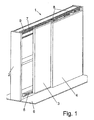
- a sliding door cabinet 1 comprises a furniture body 2, on which two sliding elements 3 and 4 are mounted displaceably on a front side.
- a lower guide rail 5 is provided, which is arranged at a distance from the bottom 6.
- an upper guide rail 7 is provided, on which the sliding elements 3 and 4 are mounted, wherein the front sliding element 4 is held on bracket 8 on the guide rail 7.
- the sliding element 4 is mounted in the lower region via further bracket 22 so that the sliding elements 3 and 4 can be moved to a position one behind the other to open the sliding door cabinet 1.
- a light bar 10 is provided on the side of a cap 9 is provided with an energy storage or a connection for connection to a power grid.
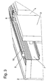
- FIG. 3 the upper portion of the guide rail fitting is shown in detail, wherein the guide rail 7 is fixed to a ceiling of the furniture body 2.
- the guide rail 7 has a substantially C-shaped cross section, wherein the bracket 8 are guided over rollers on the lower leg and the light bar 10 is mounted in the region of the upper leg.
- the light strip 10 may be latched, glued or mechanically fixed to the guide rail 7.
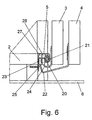
- the light bar 10 is shown enlarged.
- the light strip 10 comprises a holding profile 11, which is fixed with a web portion 12 on the guide rail 7.
- the retaining profile 11 also has a groove with locking means 13 in the form of inwardly directed projections on which a hollow section 14 is fixed.
- the hollow profile 14 is formed of translucent plastic and engaged with a foot portion 15 in the groove of the retaining profile 11.
- an LED strip 16 is inserted with bulbs.
- the LED strip 16 is arranged so that it radiates obliquely with respect to a plane which is spanned by the sliding elements 3 and 4, ie obliquely forward and downwards.
- the hollow profile 14 can be latched to the support section 11 in a modified position in which the hollow section 14 is rotated by 180 °, so that the LED bar 16 instead down now radiates upwards.
- the light strip 10 is arranged behind the sliding door elements 3 and 4, so that a person standing in front of the sliding door elements 3 and 4 can not be dazzled by direct light. Rather, the light strip 10 radiates light so that it only indirectly reaches the person via the ceiling. If the sliding door elements 3 or 4 are opened, however, the light strip 10 can provide for an illumination of the interior.
- the guide rail 5 comprises a first groove 27, in which a slider 23 is arranged for guiding the sliding element 4 via a bracket 22, and a second groove 28, are provided in the sliders 25 which hold the sliding element 3 via one or more brackets 24 ,
- a third groove is further provided, in which a light bar 20 is arranged.
- the light strip 20 comprises a hollow profile, which is formed as in the upper light strip 10.
- the light bar 20 again has an LED strip 21 which is arranged in the hollow profile and radiates obliquely down the front, the light is reflected by the bottom 6 to the front.
- the guide rail 5 has a protruding ridge on which a plurality of openings are provided with screws 26 for fixing to the furniture body 2.
- the grooves 27 and 28 are open at the bottom and are used for lateral guidance of the sliding elements 3 and 4.
- the foremost groove is latched to the light bar 20, wherein a foot portion 29 engages in the groove.
- the light bar 20 is closed by a cap 30, which is connected to a power supply in the form of batteries or a connection for connection to a power grid.
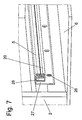
- the guide rail fitting is shown in the upper area, with only the arrangement of the light bar is changed.
- the guide rail fitting comprises the guide rail 7, on which rollers 41 are mounted on the lower leg, which hold the front sliding element 4 via a bracket 8.
- the lower sliding element 3 is also mounted on rollers 40 on the lower leg of the guide rail 7.
- a stopper 42 is provided, which limits the maximum sliding path of the sliding elements 3 and 4 relative to each other as a stop.
- a light bar 44 is not at the top of the guide rail 7 but below arranged on the guide rail 7.
- the light strip 44 is mounted on a holding profile 43 which is arranged in the region of the guide rail 7.
- a groove is formed, into which a foot 45 of a hollow profile engages, in which an LED strip 46 is arranged.
- the hollow profile may be formed as in the previous embodiment.
- the light bar 44 radiates obliquely downward light and can thus illuminate the interior of the sliding door cabinet well.
- a modified embodiment of the guide rail fitting is shown in the upper region, in which on the guide rail 7, a light bar 50 is provided.
- the light bar 50 is substantially in cross section square or rectangular and comprises a hollow profile 55 which is glued to a bottom 51 on a groove 52 of the guide rail 7 or fixed by other fastening means.
- the LED strip is arranged at a distance from the surrounding hollow profile 55, as in the preceding exemplary embodiments.
- the light bar extends over almost the entire width of the sliding elements 3 and 4, but at least over more than 70%. It is of course possible to form the light bar interrupted for each sliding element and set in individual sections on the guide rail 5 and 7 respectively.
- the light strips can be coupled to each other via connectors, so that they can be easily adapted to different widths of guide rails.
- the light strips can be fixed both mechanically by latching, or other mechanical fastening means to the support profiles or guide rails.
Landscapes
- Engineering & Computer Science (AREA)
- General Engineering & Computer Science (AREA)
- Health & Medical Sciences (AREA)
- Public Health (AREA)
- Planar Illumination Modules (AREA)
- Closing And Opening Devices For Wings, And Checks For Wings (AREA)
- Arrangements Of Lighting Devices For Vehicle Interiors, Mounting And Supporting Thereof, Circuits Therefore (AREA)
- Curtains And Furnishings For Windows Or Doors (AREA)
- Seats For Vehicles (AREA)
Abstract
Description
Die vorliegende Erfindung betrifft einen Führungsschienenbeschlag, insbesondere für einen Schiebetürenschrank, mit einer oberen Führungsschiene und einer unteren Führungsschiene, an denen mindestens ein Schiebeelement verschiebbar gelagert ist.The present invention relates to a guide rail fitting, in particular for a sliding door cabinet, with an upper guide rail and a lower guide rail, on which at least one sliding element is slidably mounted.
Es gibt Schiebetürenschränke mit einem Führungsschienenbeschlag, bei dem mehrere Schiebeelemente hintereinander geführt sind und zum Öffnen des Schrankes in eine im Wesentlichen überdeckende Position bewegt werden können. Bei solchen Schiebetürenschränken ist es auch bekannt, gerade im oberen Bereich eine über die Schiebetürenelemente hervorstehende Leiste mit einzelnen Leuchtmitteln vorzusehen. Die meist punktförmig abstrahlenden Leuchtmittel können im Bereich vor den Schiebetürenelementen beleuchten, sind jedoch vergleichsweise hell und können dabei blenden. Zudem wird eine zu intensive Lichteinstrahlung meist als störend empfunden.There are sliding door cabinets with a guide rail fitting, in which a plurality of sliding elements are guided one behind the other and can be moved to open the cabinet in a substantially overlapping position. In such sliding door cabinets, it is also known to provide just above the sliding door elements protruding bar with individual bulbs in the upper area. The usually punctiform radiating bulbs can illuminate in the area in front of the sliding door elements, but are relatively bright and can dazzle. In addition, too intense exposure to light is usually perceived as disturbing.
Das Dokument
Es ist daher Aufgabe der vorliegenden Erfindung einen verbesserten Führungsschienenbeschlag mit einer oberen und einer unteren Führungsschiene mit mindestens einer Lichtleiste bereitzustellen, welcher bei kompaktem Aufbau eine reduzierte Bauteilezahl, leistungsreduzierte Leuchtmittel mit angenehmer Beleuchtung und einfache Montage ermöglicht.It is therefore an object of the present invention to provide an improved guide rail fitting with an upper and a lower guide rail with at least one light bar, which allows a compact design, a reduced number of components, reduced-power lighting with pleasant lighting and easy installation.
Diese Aufgabe wird mit einem Führungsschienenbeschlag mit den Merkmalen des Anspruches 1 gelöst.This object is achieved with a guide rail fitting with the features of
Erfindungsgemäß ist an mindestens einer Führungsschiene des Führungsschienenbeschlages eine Lichtleiste zur Beleuchtung vorgesehen. Dadurch kann der Führungsschienenbeschlag sowohl zum Führen der Schiebeelemente als auch zur Beleuchtung eingesetzt werden.According to the invention, a light strip is provided for illumination on at least one guide rail of the guide rail fitting. As a result, the guide rail fitting can be used both for guiding the sliding elements and for lighting.
Vorzugsweise ist die Lichtleiste hinter den Schiebeelementen angeordnet und strahlt im Wesentlichen indirektes Licht über den Boden bzw. die Decke vor das Schiebeelement ab. Ein solches indirektes Licht wird vom Betrachter als angenehm empfunden, da er nicht geblendet wird und die Beleuchtung eine gewisse Raumausleuchtung schafft. Wenn ein Schiebetürenelement geöffnet wird, kann der Benutzer jedoch den Innenraum gut wahrnehmen, da die Beleuchtung im Bereich des Führungsschienenbeschlages im Innenraum ein helleres Licht bereitstellt.Preferably, the light bar is arranged behind the sliding elements and radiates substantially indirect light over the floor or the ceiling in front of the sliding element. Such an indirect light is perceived by the viewer as pleasant because it is not dazzled and the lighting creates a certain room illumination. However, when a sliding door member is opened, the user can well perceive the interior because the illumination in the area of the guide rail fitting in the interior provides brighter light.
Die Lichtleiste erstreckt sich vorzugsweise über mehr als 70%, bzw. mehr als 80% der Länge der Führungsschiene, so dass eine Ausleuchtung im Wesentlichen über die ganze Breite des Führungsschienenbeschlages möglich ist.The light strip preferably extends over more than 70%, or more than 80% of the length of the guide rail, so that illumination is possible substantially over the entire width of the guide rail fitting.
Die Lichtleiste kann dabei eine LED-Leiste umfassen, so dass bei geringem Stromverbrauch und geringer Wärmeentwicklung eine gute Ausleuchtung erhalten wird. Dabei kann die Lichtleiste ein Hohlprofil umfassen, in dem die LED-Leiste angeordnet ist, beispielsweise durch Einschieben. Es ist auch möglich, die LED-Leiste nur an einem Profil außen zu befestigen, wobei die Anordnung in einem Hohlprofil auch einen Schutz gegen Verschmutzung bereitstellt. Das Hohlprofil kann dabei aus transluzentem Kunststoff oder Glas gebildet sein.The light bar can include an LED bar, so that with low power consumption and low heat generation a good illumination is obtained. In this case, the light bar may comprise a hollow profile in which the LED strip is arranged, for example by inserting. It is also possible to attach the LED strip outside only on a profile, the arrangement also provides protection against contamination in a hollow profile. The hollow profile can be formed from translucent plastic or glass.
Für eine einfache Montage kann die Lichtleiste an einer Führungsschiene oder einem Halteprofil verrastet sein. Dabei kann die Lichtleiste gegenüber einer Ebene, die durch ein Schiebeelement aufgespannt ist, schräg abstrahlen. Das Abstrahlen nach vorne bzw. nach hinten hat den Vorteil, dass die Beleuchtung gezielt, eingesetzt werden kann, beispielsweise als indirekte Beleuchtung für einen Raum oder als Beleuchtung für den Innenraum eines Schiebetürenschrankes. Durch ein Verrasten der Lichtleiste kann die Richtung der Abstrahlung des Lichtes auch noch während der Montage eingestellt werden.For easy installation, the light bar can be locked to a guide rail or a holding profile. In this case, the light bar with respect to a plane which is spanned by a sliding element, radiate obliquely. The blasting to the front or to the rear has the advantage that the lighting can be targeted, used, for example, as an indirect lighting for a room or as lighting for the interior of a sliding door cabinet. By locking the light bar, the direction of the radiation of the light can also be adjusted during assembly.
Für einen einfachen Aufbau ist die Lichtleiste seitlich mit einer Kappe mit einem Energiespeicher verschlossen. Alternativ kann die Lichtleiste auch seitlich mit einem Anschluss zu einer Stromversorgung verbunden sein, beispielsweise über einen Transformator.For a simple construction, the light strip is closed at the side with a cap with an energy store. Alternatively, the light bar can also be connected laterally with a connection to a power supply, for example via a transformer.
Der Führungsschienenbeschlag umfasst vorzugsweise sowohl eine obere Führungsschiene als auch eine untere Führungsschiene, an der jeweils eine Lichtleiste vorgesehen ist. Dies sorgt für eine besonders gute Raumausleuchtung innen bzw. außen. Dabei können an der unteren Führungsschiene zwei Nuten zur Führung zweier Schiebeelemente und eine Nut zur Festlegung einer Lichtleiste vorgesehen sein. Zur Führung eines dritten Schiebeelementes kann auch noch eine weitere Nut ergänzt sein.The guide rail fitting preferably comprises both an upper guide rail and a lower guide rail, on each of which a light strip is provided. This ensures a particularly good room illumination inside or outside. In this case, two grooves for guiding two sliding elements and a groove for fixing a light bar can be provided on the lower guide rail. To guide a third sliding element can also be supplemented another groove.
Die Erfindung wird nachfolgend anhand mehrerer Ausführungsbeispiele mit Bezug auf die beigefügten Zeichnungen erläutert. Es zeigen:
Figur 1- eine perspektivische Ansicht eines Schiebetürenschrankes mit einem erfindungsgemäßen Führungsschienenbeschlag;
Figur 2- eine perspektivische Ansicht des Schiebetürenschrankes der
Figur 1 Figur 3- eine perspektivische Ansicht des oberen Bereiches des Führungsschienenbeschlages;
Figur 4- eine Detailansicht der Lichtleiste des Führungsschienenbeschlages der
Figur 1 Figur 5- eine Detailansicht der Lichtleiste in modifizierter Einbausituation;
Figur 6- eine Seitenansicht des Führungsschienenbeschlages der
Figur 1 Figur 7- eine Detailansicht der Lichtleiste des Führungsschienenbeschlages der
Figur 6 Figur 8- eine perspektivische Ansicht der Lichtleiste des Führungsschienenbeschlages der
Figur 6 Figur 9- eine Detailansicht der Lichtleiste des Führungsschienenbeschlages der
Figur 6 Figur 10- eine Seitenansicht des Führungsschienenbeschlages der
Figur 1 Figur 11- eine perspektivische Ansicht des Führungsschienenbeschlages der
Figur 10 Figur 12- eine perspektivische Ansicht eines Führungsschienenbeschlages mit modifizierter Lichtleiste, und
Figur 13- eine Detailansicht des Führungsschienenbeschlages der
Figur 12
- FIG. 1
- a perspective view of a sliding door cabinet with a guide rail fitting according to the invention;
- FIG. 2
- a perspective view of the sliding door cabinet of the
FIG. 1 in an enlarged view; - FIG. 3
- a perspective view of the upper portion of the guide rail fitting;
- FIG. 4
- a detailed view of the light bar of the guide rail fitting of
FIG. 1 ; - FIG. 5
- a detailed view of the light bar in a modified installation situation;
- FIG. 6
- a side view of the guide rail fitting of
FIG. 1 in the area below; - FIG. 7
- a detailed view of the light bar of the guide rail fitting of
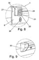
FIG. 6 ; - FIG. 8
- a perspective view of the light bar of the guide rail fitting of
FIG. 6 ; - FIG. 9
- a detailed view of the light bar of the guide rail fitting of
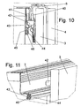
FIG. 6 ; - FIG. 10
- a side view of the guide rail fitting of
FIG. 1 with modified light strip; - FIG. 11
- a perspective view of the guide rail fitting of
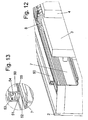
FIG. 10 ; - FIG. 12
- a perspective view of a guide rail fitting with modified light bar, and
- FIG. 13
- a detailed view of the guide rail fitting of
FIG. 12 ,
Ein Schiebetürenschrank 1 umfasst einen Möbelkorpus 2, an dem an einer Frontseite zwei Schiebeelemente 3 und 4 verschiebbar gelagert sind. Hierfür ist eine untere Führungsschiene 5 vorgesehen, die beabstandet von dem Boden 6 angeordnet ist. An der Oberseite ist eine obere Führungsschiene 7 vorgesehen, an der die Schiebeelemente 3 und 4 gelagert sind, wobei das vordere Schiebeelement 4 über Bügel 8 an der Führungsschiene 7 gehalten ist.A sliding
Wie aus
In
In
Wie in
In
Wie in den
Die vorderste Nut ist mit der Lichtleiste 20 verrastet, wobei ein Fußabschnitt 29 in die Nut eingreift. Seitlich ist die Lichtleiste 20 über eine Kappe 30 verschlossen, die mit einer Stromversorgung in Form von Batterien oder einem Anschluss zur Verbindung mit einem Stromnetz verbunden ist.The foremost groove is latched to the
In
Bei diesem Ausführungsbeispiel ist an der Führungsschiene 7 eine Lichtleiste 44 nicht oben an der Führungsschiene 7 sondern unten angeordnet. Die Lichtleiste 44 ist an einem Halteprofil 43 montiert, das im Bereich der Führungsschiene 7 angeordnet ist. An dem Halteprofil 43 ist eine Nut ausgebildet, in die ein Fuß 45 eines Hohlprofils eingreift, in dem eine LED-Leiste 46 angeordnet ist. Das Hohlprofil kann wie bei dem vorangegangenen Ausführungsbeispiel ausgebildet sein. Die Lichtleiste 44 strahlt schräg nach unten Licht ab und kann somit den Innenraum des Schiebetürenschrankes gut ausleuchten.In this embodiment, a
In den
In den dargestellten Ausführungsbeispielen erstreckt sich die Lichtleiste über fast die gesamte Breite der Schiebeelemente 3 und 4, zumindest jedoch über mehr als 70%. Es ist natürlich möglich, die Lichtleiste auch unterbrochen für jedes Schiebeelement auszubilden und in einzelnen Abschnitten an der Führungsschiene 5 bzw. 7 festzulegen. Die Lichtleisten können dabei über Steckverbindungen miteinander gekoppelt werden, so dass sie auf einfache Weise an unterschiedliche Breiten von Führungsschienen angepasst werden können. Die Lichtleisten können dabei sowohl mechanisch über Verrasten, oder andere mechanische Befestigungsmittel an den Halteprofilen oder Führungsschienen festgelegt werden. Zudem ist es auch möglich die Lichtleiste anklettbar oder anklebbar auszugestalten. Dadurch können die Lichtleisten auf einfache Weise auch an schon montierten Führungsschienenbeschlägen nachträglich montiert werden.In the illustrated embodiments, the light bar extends over almost the entire width of the sliding
Claims (10)
- Guide rail fitting, in particular for a sliding door cabinet, having an upper guide rail (7) and a lower guide rail (5), on which at least one sliding element (3, 4) is mounted such that it can move, with a light strip (10, 20, 44, 50) being provided on at least one guide rail (5, 7) for illumination, characterized in that the at least one light strip comprises an LED strip (16, 21, 46, 53) and a hollow profile (14, 55) in which an LED strip (16, 21, 46, 53) is arranged, and in that one LED strip (16, 21, 46, 53) can be coupled to further LED strips (16, 21, 46, 53) via plug connections.
- Guide rail fitting according to Claim 1, characterized in that the light strip (10, 20, 44, 50) is arranged behind the sliding element (3, 4), and the light emitted from it is reflected substantially via a floor or a ceiling and arrives as indirect light in front of the sliding element (3, 4).
- Guide rail fitting according to Claim 1 or 2, characterized in that the light strip (10, 20, 44, 50) extends over more than 70%, preferably more than 80%, of the length of the guide rail (5, 7).
- Guide rail fitting according to one of Claims 1 to 3, characterized in that the hollow profile (14, 55) is formed from translucent plastic material.
- Guide rail fitting according to one of Claims 1 to 4, characterized in that the light strip (10, 20, 44, 50) is latched to a guide rail (5, 7) or to a holding profile (11).
- Guide rail fitting according to one of Claims 1 to 5, characterized in that the light strip (10, 20, 44, 50) emits obliquely with respect to a plane which is covered by the sliding element (3, 4).
- Guide rail fitting according to one of Claims 1 to 6, characterized in that the light strip (10, 20, 44, 50) is closed at the side by a cap (9, 30) having an energy store.
- Guide rail fitting according to one of Claims 1 to 6, characterized in that the light strip is connected at the side to a connection for a power supply.
- Guide rail fitting according to one of Claims 1 to 8, characterized in that a light strip (10, 20) is provided both on the upper guide rail (7) and on the lower guide rail (5).
- Guide rail fitting according to one of Claims 1 to 9, characterized in that two grooves for guidance of two sliding elements (3, 4) and one groove for fixing a light strip (20) are provided on the lower guide rail (5).
Applications Claiming Priority (1)
| Application Number | Priority Date | Filing Date | Title |
|---|---|---|---|
| DE202007006688U DE202007006688U1 (en) | 2007-05-07 | 2007-05-07 | Guide rail fitting |
Publications (3)
| Publication Number | Publication Date |
|---|---|
| EP1992873A2 EP1992873A2 (en) | 2008-11-19 |
| EP1992873A3 EP1992873A3 (en) | 2010-07-28 |
| EP1992873B1 true EP1992873B1 (en) | 2011-08-17 |
Family
ID=39494478
Family Applications (1)
| Application Number | Title | Priority Date | Filing Date |
|---|---|---|---|
| EP08102978A Not-in-force EP1992873B1 (en) | 2007-05-07 | 2008-03-27 | Guide rail fitting |
Country Status (5)
| Country | Link |
|---|---|
| EP (1) | EP1992873B1 (en) |
| AT (1) | ATE520932T1 (en) |
| DE (1) | DE202007006688U1 (en) |
| ES (1) | ES2371295T3 (en) |
| RU (1) | RU2008116737A (en) |
Families Citing this family (7)
| Publication number | Priority date | Publication date | Assignee | Title |
|---|---|---|---|---|
| DE202010000363U1 (en) * | 2010-03-12 | 2011-04-21 | Warendorfer Küchen GmbH | Lighting for the base area of a piece of furniture |
| AT509686B1 (en) * | 2010-04-09 | 2011-11-15 | Hierzer Andreas | MOUNTING PROFILE WITH AT LEAST ONE LIGHTING UNIT |
| DE202011000490U1 (en) * | 2011-03-04 | 2012-03-06 | Gera-Leuchten Gmbh | Recessed light for a cabinet, a shelf or the like |
| GB201208007D0 (en) * | 2012-05-08 | 2012-06-20 | Metal Office Equipment Ltd | Office cabinet |
| FR3010173B1 (en) * | 2013-09-03 | 2018-01-05 | Optimum | AUTOMATIC AND AUTONOMOUS LIGHTING DEVICE FOR A CUPBOARD DOOR |
| DE102014011819A1 (en) * | 2014-08-08 | 2016-02-11 | Ambright GmbH | Waterproof luminaire |
| US10465431B2 (en) * | 2017-03-21 | 2019-11-05 | Schneider Electric It Corporation | Pneumatic bi-parting door system without a floor track in the doorway for data center aisle containment |
Family Cites Families (8)
| Publication number | Priority date | Publication date | Assignee | Title |
|---|---|---|---|---|
| CH682710A5 (en) * | 1991-11-12 | 1993-11-15 | Eku Ag | Track shield for cupboard with sliding door - has sprung latches to engage on holding cams on track and has groove to accommodate decoration or notes |
| US6585393B1 (en) * | 1998-10-09 | 2003-07-01 | Satco Products, Inc. | Modular accent light fixture |
| DE20020751U1 (en) * | 2000-12-07 | 2001-02-15 | Briloner Leuchten GmbH, 59929 Brilon | Surface-mounted luminaire |
| DE20303045U1 (en) * | 2003-02-24 | 2003-04-30 | Gera-Leuchten GmbH, 07629 St Gangloff | Guides, for transparent sliding doors, comprises lamp holding facility integrated in upper profile |
| US20040246720A1 (en) * | 2003-06-04 | 2004-12-09 | Koski Craig O. | Remote control actuated art lamp |
| US7066619B2 (en) * | 2003-08-29 | 2006-06-27 | Waters Michael A | LED picture light apparatus and method |
| US7213941B2 (en) * | 2004-04-14 | 2007-05-08 | Sloanled, Inc. | Flexible perimeter lighting apparatus |
| DE202007007682U1 (en) * | 2006-08-24 | 2007-08-02 | Wu, Yulin, Foshan | Guide rail lamp, has illuminant such as light emitting diode, and light guiding body that are arranged in area of fasteners, such that light radiating from light emitting diode is introduced into light guiding pipes |
-
2007
- 2007-05-07 DE DE202007006688U patent/DE202007006688U1/en not_active Expired - Lifetime
-
2008
- 2008-03-27 AT AT08102978T patent/ATE520932T1/en active
- 2008-03-27 ES ES08102978T patent/ES2371295T3/en active Active
- 2008-03-27 EP EP08102978A patent/EP1992873B1/en not_active Not-in-force
- 2008-04-30 RU RU2008116737/12A patent/RU2008116737A/en unknown
Also Published As
| Publication number | Publication date |
|---|---|
| ES2371295T3 (en) | 2011-12-29 |
| EP1992873A3 (en) | 2010-07-28 |
| EP1992873A2 (en) | 2008-11-19 |
| ATE520932T1 (en) | 2011-09-15 |
| RU2008116737A (en) | 2009-11-10 |
| DE202007006688U1 (en) | 2008-09-18 |
Similar Documents
| Publication | Publication Date | Title |
|---|---|---|
| EP1992873B1 (en) | Guide rail fitting | |
| EP2243998B1 (en) | Wall and ceiling system | |
| DE102011103319B4 (en) | Ambient lighting integrated into a sunroof or dimming system | |
| AT519174B1 (en) | Lighting arrangement, kit for a lighting arrangement, as well as a method for building a lighting arrangement | |
| EP3270047A2 (en) | Flat light | |
| AT509686B1 (en) | MOUNTING PROFILE WITH AT LEAST ONE LIGHTING UNIT | |
| DE69907078T2 (en) | Illuminated shelf | |
| DE202012101627U1 (en) | Cabinet door with light-grip hollow | |
| DE202010000997U1 (en) | Device for illuminating an environment and / or an interior of a movable furniture part | |
| DE202010001579U1 (en) | Lighting device for a movable furniture element and furniture element | |
| DE102015212299A1 (en) | Extractor hood with sliding pull-out screen | |
| DE8633747U1 (en) | Curtain lighting | |
| EP3022505A1 (en) | Domestic cooling appliance having at least one light source and a receiving means for a shelf | |
| DE102012207540A1 (en) | lamp | |
| DE202011110252U1 (en) | Switch device for a closet and closet with such a device | |
| DE102016104448A1 (en) | flat light | |
| EP2208192B1 (en) | Pictogram lamp | |
| DE102009045961A1 (en) | Lighting device for a kitchen work surface and kitchen element with a kitchen work surface and at least one lighting device | |
| DE102006015205B4 (en) | Lighting device for a kitchen furniture | |
| WO2016037744A1 (en) | Profiled element | |
| DE69407582T2 (en) | Guide rail for sliding curtains | |
| EP1477725A2 (en) | Wall-mounted luminaire | |
| DE202012011993U1 (en) | Guide device for guiding a relative to a furniture body movable furniture part | |
| DE202016106962U1 (en) | Awning, in particular conservatory awning, with lighting | |
| DE202004019070U1 (en) | Kitchen wall unit has top and base consisting of glass plates, between which lights are mounted |
Legal Events
| Date | Code | Title | Description |
|---|---|---|---|
| PUAI | Public reference made under article 153(3) epc to a published international application that has entered the european phase |
Free format text: ORIGINAL CODE: 0009012 |
|
| AK | Designated contracting states |
Kind code of ref document: A2 Designated state(s): AT BE BG CH CY CZ DE DK EE ES FI FR GB GR HR HU IE IS IT LI LT LU LV MC MT NL NO PL PT RO SE SI SK TR |
|
| AX | Request for extension of the european patent |
Extension state: AL BA MK RS |
|
| PUAL | Search report despatched |
Free format text: ORIGINAL CODE: 0009013 |
|
| AK | Designated contracting states |
Kind code of ref document: A3 Designated state(s): AT BE BG CH CY CZ DE DK EE ES FI FR GB GR HR HU IE IS IT LI LT LU LV MC MT NL NO PL PT RO SE SI SK TR |
|
| AX | Request for extension of the european patent |
Extension state: AL BA MK RS |
|
| 17P | Request for examination filed |
Effective date: 20110124 |
|
| GRAP | Despatch of communication of intention to grant a patent |
Free format text: ORIGINAL CODE: EPIDOSNIGR1 |
|
| AKX | Designation fees paid |
Designated state(s): AT BE BG CH CY CZ DE DK EE ES FI FR GB GR HR HU IE IS IT LI LT LU LV MC MT NL NO PL PT RO SE SI SK TR |
|
| RIC1 | Information provided on ipc code assigned before grant |
Ipc: F21Y 101/02 20060101ALN20110317BHEP Ipc: F21V 33/00 20060101AFI20110317BHEP |
|
| GRAS | Grant fee paid |
Free format text: ORIGINAL CODE: EPIDOSNIGR3 |
|
| GRAA | (expected) grant |
Free format text: ORIGINAL CODE: 0009210 |
|
| AK | Designated contracting states |
Kind code of ref document: B1 Designated state(s): AT BE BG CH CY CZ DE DK EE ES FI FR GB GR HR HU IE IS IT LI LT LU LV MC MT NL NO PL PT RO SE SI SK TR |
|
| REG | Reference to a national code |
Ref country code: GB Ref legal event code: FG4D Free format text: NOT ENGLISH |
|
| REG | Reference to a national code |
Ref country code: CH Ref legal event code: EP |
|
| REG | Reference to a national code |
Ref country code: IE Ref legal event code: FG4D Free format text: LANGUAGE OF EP DOCUMENT: GERMAN |
|
| REG | Reference to a national code |
Ref country code: CH Ref legal event code: NV Representative=s name: ISLER & PEDRAZZINI AG |
|
| REG | Reference to a national code |
Ref country code: DE Ref legal event code: R096 Ref document number: 502008004514 Country of ref document: DE Effective date: 20111020 |
|
| REG | Reference to a national code |
Ref country code: NL Ref legal event code: VDEP Effective date: 20110817 |
|
| REG | Reference to a national code |
Ref country code: ES Ref legal event code: FG2A Ref document number: 2371295 Country of ref document: ES Kind code of ref document: T3 Effective date: 20111229 |
|
| LTIE | Lt: invalidation of european patent or patent extension |
Effective date: 20110817 |
|
| PG25 | Lapsed in a contracting state [announced via postgrant information from national office to epo] |
Ref country code: SE Free format text: LAPSE BECAUSE OF FAILURE TO SUBMIT A TRANSLATION OF THE DESCRIPTION OR TO PAY THE FEE WITHIN THE PRESCRIBED TIME-LIMIT Effective date: 20110817 Ref country code: PT Free format text: LAPSE BECAUSE OF FAILURE TO SUBMIT A TRANSLATION OF THE DESCRIPTION OR TO PAY THE FEE WITHIN THE PRESCRIBED TIME-LIMIT Effective date: 20111219 Ref country code: NO Free format text: LAPSE BECAUSE OF FAILURE TO SUBMIT A TRANSLATION OF THE DESCRIPTION OR TO PAY THE FEE WITHIN THE PRESCRIBED TIME-LIMIT Effective date: 20111117 Ref country code: NL Free format text: LAPSE BECAUSE OF FAILURE TO SUBMIT A TRANSLATION OF THE DESCRIPTION OR TO PAY THE FEE WITHIN THE PRESCRIBED TIME-LIMIT Effective date: 20110817 Ref country code: FI Free format text: LAPSE BECAUSE OF FAILURE TO SUBMIT A TRANSLATION OF THE DESCRIPTION OR TO PAY THE FEE WITHIN THE PRESCRIBED TIME-LIMIT Effective date: 20110817 Ref country code: IS Free format text: LAPSE BECAUSE OF FAILURE TO SUBMIT A TRANSLATION OF THE DESCRIPTION OR TO PAY THE FEE WITHIN THE PRESCRIBED TIME-LIMIT Effective date: 20111217 Ref country code: LT Free format text: LAPSE BECAUSE OF FAILURE TO SUBMIT A TRANSLATION OF THE DESCRIPTION OR TO PAY THE FEE WITHIN THE PRESCRIBED TIME-LIMIT Effective date: 20110817 |
|
| PG25 | Lapsed in a contracting state [announced via postgrant information from national office to epo] |
Ref country code: PL Free format text: LAPSE BECAUSE OF FAILURE TO SUBMIT A TRANSLATION OF THE DESCRIPTION OR TO PAY THE FEE WITHIN THE PRESCRIBED TIME-LIMIT Effective date: 20110817 Ref country code: CY Free format text: LAPSE BECAUSE OF FAILURE TO SUBMIT A TRANSLATION OF THE DESCRIPTION OR TO PAY THE FEE WITHIN THE PRESCRIBED TIME-LIMIT Effective date: 20110817 Ref country code: LV Free format text: LAPSE BECAUSE OF FAILURE TO SUBMIT A TRANSLATION OF THE DESCRIPTION OR TO PAY THE FEE WITHIN THE PRESCRIBED TIME-LIMIT Effective date: 20110817 Ref country code: GR Free format text: LAPSE BECAUSE OF FAILURE TO SUBMIT A TRANSLATION OF THE DESCRIPTION OR TO PAY THE FEE WITHIN THE PRESCRIBED TIME-LIMIT Effective date: 20111118 Ref country code: SI Free format text: LAPSE BECAUSE OF FAILURE TO SUBMIT A TRANSLATION OF THE DESCRIPTION OR TO PAY THE FEE WITHIN THE PRESCRIBED TIME-LIMIT Effective date: 20110817 |
|
| REG | Reference to a national code |
Ref country code: IE Ref legal event code: FD4D |
|
| PG25 | Lapsed in a contracting state [announced via postgrant information from national office to epo] |
Ref country code: SK Free format text: LAPSE BECAUSE OF FAILURE TO SUBMIT A TRANSLATION OF THE DESCRIPTION OR TO PAY THE FEE WITHIN THE PRESCRIBED TIME-LIMIT Effective date: 20110817 Ref country code: CZ Free format text: LAPSE BECAUSE OF FAILURE TO SUBMIT A TRANSLATION OF THE DESCRIPTION OR TO PAY THE FEE WITHIN THE PRESCRIBED TIME-LIMIT Effective date: 20110817 Ref country code: IE Free format text: LAPSE BECAUSE OF FAILURE TO SUBMIT A TRANSLATION OF THE DESCRIPTION OR TO PAY THE FEE WITHIN THE PRESCRIBED TIME-LIMIT Effective date: 20110817 |
|
| PGFP | Annual fee paid to national office [announced via postgrant information from national office to epo] |
Ref country code: CH Payment date: 20120323 Year of fee payment: 5 |
|
| PG25 | Lapsed in a contracting state [announced via postgrant information from national office to epo] |
Ref country code: RO Free format text: LAPSE BECAUSE OF FAILURE TO SUBMIT A TRANSLATION OF THE DESCRIPTION OR TO PAY THE FEE WITHIN THE PRESCRIBED TIME-LIMIT Effective date: 20110817 Ref country code: EE Free format text: LAPSE BECAUSE OF FAILURE TO SUBMIT A TRANSLATION OF THE DESCRIPTION OR TO PAY THE FEE WITHIN THE PRESCRIBED TIME-LIMIT Effective date: 20110817 |
|
| PGFP | Annual fee paid to national office [announced via postgrant information from national office to epo] |
Ref country code: TR Payment date: 20120320 Year of fee payment: 5 |
|
| PLBE | No opposition filed within time limit |
Free format text: ORIGINAL CODE: 0009261 |
|
| STAA | Information on the status of an ep patent application or granted ep patent |
Free format text: STATUS: NO OPPOSITION FILED WITHIN TIME LIMIT |
|
| PG25 | Lapsed in a contracting state [announced via postgrant information from national office to epo] |
Ref country code: DK Free format text: LAPSE BECAUSE OF FAILURE TO SUBMIT A TRANSLATION OF THE DESCRIPTION OR TO PAY THE FEE WITHIN THE PRESCRIBED TIME-LIMIT Effective date: 20110817 |
|
| PGFP | Annual fee paid to national office [announced via postgrant information from national office to epo] |
Ref country code: IT Payment date: 20120326 Year of fee payment: 5 |
|
| 26N | No opposition filed |
Effective date: 20120521 |
|
| PG25 | Lapsed in a contracting state [announced via postgrant information from national office to epo] |
Ref country code: HR Free format text: LAPSE BECAUSE OF FAILURE TO SUBMIT A TRANSLATION OF THE DESCRIPTION OR TO PAY THE FEE WITHIN THE PRESCRIBED TIME-LIMIT Effective date: 20120321 |
|
| REG | Reference to a national code |
Ref country code: DE Ref legal event code: R097 Ref document number: 502008004514 Country of ref document: DE Effective date: 20120521 |
|
| BERE | Be: lapsed |
Owner name: HETTICH-HEINZE G.M.B.H. & CO. KG Effective date: 20120331 |
|
| PG25 | Lapsed in a contracting state [announced via postgrant information from national office to epo] |
Ref country code: MC Free format text: LAPSE BECAUSE OF NON-PAYMENT OF DUE FEES Effective date: 20120331 |
|
| GBPC | Gb: european patent ceased through non-payment of renewal fee |
Effective date: 20120327 |
|
| REG | Reference to a national code |
Ref country code: FR Ref legal event code: ST Effective date: 20121130 |
|
| PG25 | Lapsed in a contracting state [announced via postgrant information from national office to epo] |
Ref country code: BE Free format text: LAPSE BECAUSE OF NON-PAYMENT OF DUE FEES Effective date: 20120331 Ref country code: GB Free format text: LAPSE BECAUSE OF NON-PAYMENT OF DUE FEES Effective date: 20120327 Ref country code: FR Free format text: LAPSE BECAUSE OF NON-PAYMENT OF DUE FEES Effective date: 20120402 |
|
| PG25 | Lapsed in a contracting state [announced via postgrant information from national office to epo] |
Ref country code: BG Free format text: LAPSE BECAUSE OF FAILURE TO SUBMIT A TRANSLATION OF THE DESCRIPTION OR TO PAY THE FEE WITHIN THE PRESCRIBED TIME-LIMIT Effective date: 20111117 |
|
| PGFP | Annual fee paid to national office [announced via postgrant information from national office to epo] |
Ref country code: ES Payment date: 20120326 Year of fee payment: 5 |
|
| PG25 | Lapsed in a contracting state [announced via postgrant information from national office to epo] |
Ref country code: MT Free format text: LAPSE BECAUSE OF FAILURE TO SUBMIT A TRANSLATION OF THE DESCRIPTION OR TO PAY THE FEE WITHIN THE PRESCRIBED TIME-LIMIT Effective date: 20110817 |
|
| REG | Reference to a national code |
Ref country code: CH Ref legal event code: PL |
|
| PG25 | Lapsed in a contracting state [announced via postgrant information from national office to epo] |
Ref country code: HR Free format text: LAPSE BECAUSE OF FAILURE TO SUBMIT A TRANSLATION OF THE DESCRIPTION OR TO PAY THE FEE WITHIN THE PRESCRIBED TIME-LIMIT Effective date: 20110817 |
|
| PG25 | Lapsed in a contracting state [announced via postgrant information from national office to epo] |
Ref country code: CH Free format text: LAPSE BECAUSE OF NON-PAYMENT OF DUE FEES Effective date: 20130331 Ref country code: LI Free format text: LAPSE BECAUSE OF NON-PAYMENT OF DUE FEES Effective date: 20130331 |
|
| PG25 | Lapsed in a contracting state [announced via postgrant information from national office to epo] |
Ref country code: IT Free format text: LAPSE BECAUSE OF NON-PAYMENT OF DUE FEES Effective date: 20130327 |
|
| REG | Reference to a national code |
Ref country code: AT Ref legal event code: MM01 Ref document number: 520932 Country of ref document: AT Kind code of ref document: T Effective date: 20130327 |
|
| PG25 | Lapsed in a contracting state [announced via postgrant information from national office to epo] |
Ref country code: LU Free format text: LAPSE BECAUSE OF NON-PAYMENT OF DUE FEES Effective date: 20120327 |
|
| REG | Reference to a national code |
Ref country code: ES Ref legal event code: FD2A Effective date: 20140606 |
|
| PG25 | Lapsed in a contracting state [announced via postgrant information from national office to epo] |
Ref country code: HU Free format text: LAPSE BECAUSE OF FAILURE TO SUBMIT A TRANSLATION OF THE DESCRIPTION OR TO PAY THE FEE WITHIN THE PRESCRIBED TIME-LIMIT Effective date: 20080327 |
|
| PG25 | Lapsed in a contracting state [announced via postgrant information from national office to epo] |
Ref country code: AT Free format text: LAPSE BECAUSE OF NON-PAYMENT OF DUE FEES Effective date: 20130327 Ref country code: ES Free format text: LAPSE BECAUSE OF NON-PAYMENT OF DUE FEES Effective date: 20130328 |
|
| PG25 | Lapsed in a contracting state [announced via postgrant information from national office to epo] |
Ref country code: TR Free format text: LAPSE BECAUSE OF NON-PAYMENT OF DUE FEES Effective date: 20130327 |
|
| PGFP | Annual fee paid to national office [announced via postgrant information from national office to epo] |
Ref country code: DE Payment date: 20170327 Year of fee payment: 10 |
|
| REG | Reference to a national code |
Ref country code: DE Ref legal event code: R119 Ref document number: 502008004514 Country of ref document: DE |
|
| PG25 | Lapsed in a contracting state [announced via postgrant information from national office to epo] |
Ref country code: DE Free format text: LAPSE BECAUSE OF NON-PAYMENT OF DUE FEES Effective date: 20181002 |