EP1992849A1 - Dichtring und Dichtungsanordnung mit einem solchen - Google Patents
Dichtring und Dichtungsanordnung mit einem solchen Download PDFInfo
- Publication number
- EP1992849A1 EP1992849A1 EP07009700A EP07009700A EP1992849A1 EP 1992849 A1 EP1992849 A1 EP 1992849A1 EP 07009700 A EP07009700 A EP 07009700A EP 07009700 A EP07009700 A EP 07009700A EP 1992849 A1 EP1992849 A1 EP 1992849A1
- Authority
- EP
- European Patent Office
- Prior art keywords
- sealing
- sealed
- sealing lip
- sealing ring
- lip portion
- Prior art date
- Legal status (The legal status is an assumption and is not a legal conclusion. Google has not performed a legal analysis and makes no representation as to the accuracy of the status listed.)
- Granted
Links
- 238000007789 sealing Methods 0.000 title claims abstract description 151
- 230000007704 transition Effects 0.000 claims abstract description 7
- 230000001154 acute effect Effects 0.000 claims abstract description 5
- 230000004323 axial length Effects 0.000 claims description 8
- 238000004519 manufacturing process Methods 0.000 claims description 5
- 239000003566 sealing material Substances 0.000 claims description 3
- 239000000463 material Substances 0.000 description 3
- 238000009434 installation Methods 0.000 description 2
- -1 polytetrafluoroethylene Polymers 0.000 description 2
- 229920001343 polytetrafluoroethylene Polymers 0.000 description 2
- 239000004810 polytetrafluoroethylene Substances 0.000 description 2
- 230000003068 static effect Effects 0.000 description 2
- 230000035508 accumulation Effects 0.000 description 1
- 238000009825 accumulation Methods 0.000 description 1
- 239000011324 bead Substances 0.000 description 1
- 239000000356 contaminant Substances 0.000 description 1
- 230000001419 dependent effect Effects 0.000 description 1
- 239000007788 liquid Substances 0.000 description 1
- 238000012354 overpressurization Methods 0.000 description 1
- 230000000149 penetrating effect Effects 0.000 description 1
Images


Classifications
-
- F—MECHANICAL ENGINEERING; LIGHTING; HEATING; WEAPONS; BLASTING
- F16—ENGINEERING ELEMENTS AND UNITS; GENERAL MEASURES FOR PRODUCING AND MAINTAINING EFFECTIVE FUNCTIONING OF MACHINES OR INSTALLATIONS; THERMAL INSULATION IN GENERAL
- F16J—PISTONS; CYLINDERS; SEALINGS
- F16J15/00—Sealings
- F16J15/16—Sealings between relatively-moving surfaces
- F16J15/32—Sealings between relatively-moving surfaces with elastic sealings, e.g. O-rings
- F16J15/3244—Sealings between relatively-moving surfaces with elastic sealings, e.g. O-rings with hydrodynamic pumping action
-
- F—MECHANICAL ENGINEERING; LIGHTING; HEATING; WEAPONS; BLASTING
- F16—ENGINEERING ELEMENTS AND UNITS; GENERAL MEASURES FOR PRODUCING AND MAINTAINING EFFECTIVE FUNCTIONING OF MACHINES OR INSTALLATIONS; THERMAL INSULATION IN GENERAL
- F16J—PISTONS; CYLINDERS; SEALINGS
- F16J15/00—Sealings
- F16J15/16—Sealings between relatively-moving surfaces
- F16J15/32—Sealings between relatively-moving surfaces with elastic sealings, e.g. O-rings
- F16J15/3204—Sealings between relatively-moving surfaces with elastic sealings, e.g. O-rings with at least one lip
- F16J15/3224—Sealings between relatively-moving surfaces with elastic sealings, e.g. O-rings with at least one lip capable of accommodating changes in distances or misalignment between the surfaces, e.g. able to compensate for defaults of eccentricity or angular deviations
Definitions
- the invention relates to a sealing ring which is substantially Z-shaped, comprising a radially arranged on the one hand mounting portion and a radially outer sealing lip, which are interconnected by a connecting web, wherein the connecting web extends from the mounting portion axially in the direction of a sealed space to the sealing lip and wherein the sealing lip has a first sealing lip portion which, starting from the connecting web, extends axially against the space to be sealed.
- Such a sealing ring and a sealing arrangement comprising such a sealing ring are known from DE 103 53 305 A1 known.
- the sealing ring has a fastening part held on a first machine part and a sealing lip which sealingly bears against a second machine part when the sealing ring is mounted and is bent towards the air side.
- the sealing ring is loaded by the pressure within the space to be sealed in the direction of the sealed machine element.
- the sealing lip is correspondingly pressed firmly against the surface of the machine element to be sealed, which ensures that the radial shaft sealing ring does not lift off the surface to be sealed.
- the previously known sealing ring can be used as a radial shaft seal, piston or rod sealing ring.
- the sealing lip of the prior art sealing ring is also flexible in the radial direction,
- the prior art sealing ring is preferably made of polytetrafluoroethylene or may be made of another suitable sealing material.
- the invention has for its object to further develop a sealing ring of the known type such that the assembly of the sealing ring is further simplified, in particular that tipping of the sealing lip is reliably avoided during assembly and when acting on the sealing lip with pressure.
- a sealing ring is provided, the sealing lip has a second sealing lip portion which extends, starting from the connecting web, axially in the direction of the space to be sealed.
- the ratio of the axial length of the first sealing lip portion to the axial length of the second sealing lip portion 1 to 3, particularly preferably 2.
- the second sealing lip portion has an axial length which is about 0.8mm to 1.4mm. The axial length is measured starting from the connecting web to the axial end side of the second sealing lip portion, which faces the space to be sealed axially.
- the attachment portion and the connecting web are connected to each other by an articulated transition region.
- sealing lip and connecting web are pivotable in radial deflection movements of the sealed machine element and / or in Mathlichbeaufschlagung of the sealing ring from the space to be sealed. Due to the substantially Z-shaped configuration of the sealing ring, this comparatively large radial deflecting movements of the shaft to be sealed can follow, without causing leaks between the sealing lip and the surface to be sealed.
- the sealing ring according to the invention can be operated with low friction.
- the medium to be sealed which is located below the first sealing lip portion and ensures its low-friction running on the surface to be sealed and thus resulting in only slight wear, is pumped back by the return spin in the direction of the space to be sealed.
- the first and the second sealing lip portion have a substantially matching radial thickness and are formed during the intended use of the sealing ring without radial offset axially merging into each other,
- largely constant thickness of the sealing ring is easy to manufacture, because caused by different thicknesses material accumulations are avoided ,
- the connecting web and the sealing lip may consist of polytetrafluoroethylene or another suitable sealing material.
- the invention relates to a sealing arrangement comprising the sealing ring described above, wherein the sealing ring to be sealed Surface of a machine element to be sealed under radial elastic bias touched only with its first sealing lip portion.
- the sealing lip may include in the state of manufacture of the radial shaft sealing ring with the surface to be sealed open in the direction of the space to be sealed acute angle, which is preferably 45 °. This is advantageous in terms of ease of installation. Due to the aforementioned acute angle, the risk of damage to the sealing ring, in particular the sealing lip, during assembly is reduced to a minimum. Due to the acute-angled arrangement of the sealing lip, it is easy to mount the sealing ring, for example, thread the sealing ring onto a shaft to be sealed. After mounting the sealing ring, the sealing lip extends axially and parallel to the surface to be sealed.
- the second sealing lip portion does not touch the surface to be sealed during normal use of the sealing ring during normal use.
- the second sealing lip portion is associated with the surface to be sealed adjacent to a radial distance, wherein the gap formed by the gap is capillary-active narrowness.
- the static seal of the sealing ring at test pressure is well by such a configuration, even if the reminddrall is not closed to the air side through a web. In any case, a low-friction relative mobility of the sealing ring on the surface to be sealed is ensured by the gap.
- FIGS. 1 and 2 An embodiment of a seal assembly according to the invention with a sealing ring according to the invention is described below with reference to FIGS. 1 and 2 described in more detail.
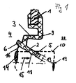
- Fig. 1 an embodiment of the sealing ring according to the invention is shown in its manufacturing condition.
- the sealed machine element 14, here a shaft to be sealed shown in dashed lines.
- the attachment portion 1 is stiffened in the embodiment shown here with a support body 18 made of a tough material.
- the connecting web 3 extends substantially parallel to the axis of symmetry 19, which simultaneously forms the axis of rotation of the machine element 14 to be sealed.
- the sealing lip 2 consists of the first sealing lip portion 5 and the second sealing lip portion 6, which are interconnected on their mutually facing sides by the connecting web 3.
- the sealing lip 2 forms with the surface 10 to be sealed, which extends parallel to the axis of symmetry 19, an open in the direction of the sealed space 4 acute angle 16, which is in the illustrated embodiment between 30 ° and 45 °.
- the largest diameter of the angularly attached sealing lip 2, namely the diameter of the end face of the second sealing lip portion 6, which faces the space to be sealed 4 axially, is significantly larger than the diameter of the surface 10 to be sealed, so that a mounting of the shaft in the mounting direction 15 easily can and the risk of damage to the sealing lip 2 and / or tipping over the sealing lip 2 in the direction of the air side 20 is reduced to a minimum.
- Fig. 2 is an embodiment of a seal assembly with the sealing ring of the invention Fig. 1 shown.
- the sealing ring is formed substantially Z-shaped, wherein the radially outwardly arranged mounting portion 1 and the radially inner side arranged sealing lip 2 are interconnected by the connecting web 3.
- the connecting web 3 extends from the mounting portion 1 axially in the direction of the space to be sealed 4 to the sealing lip 2, wherein the sealing lip 2, starting from the connecting web 3, in an axially toward the air side 20 extending first sealing lip portion 5 and axially in the direction of the sealed space. 4 extending second sealing lip portion 6 is divided.
- the two sealing lip portions 5, 6 are integrally merging into each other and of the same material formed with the connecting web 3, wherein the ratio of the axial length 7 of the first sealing lip portion 5 to the axial length 8 of the second sealing lip portion 6 in this embodiment is 2.
- the sealing lip 2 moves arcuately about the articulated transition region 9, which connects the attachment portion 1 and the connecting web 3 together.
- the first sealing lip portion 5 touches the surface 10 to be sealed, wherein the first sealing lip portion 5 on the surface 10 to be sealed radially facing side has a scruburgidrall 11 to the medium in this area to be sealed medium 12 during the intended Use in the direction of the space to be sealed 4 intimidzufördem.
- the direction of the sudurgidralls 4 depends on the direction of rotation of the machine element to be sealed 14. In general, there is also the possibility that the scrubicall 11 is designed as alternating swirl and thus seals regardless of the direction of rotation of the sealed machine element 14.
- the first 5 and the second sealing lip portion 6 are formed in the embodiment shown here consistently thick 13 and go without radial offset / without sudden change in direction into each other.
- the second sealing lip portion 6 surrounds the surface 10 to be sealed at a radial distance, wherein the gap 17 is formed by the distance.
- a contact between the sealing lip 2 and the surface to be sealed 10 takes place only in the region of the webs, which form the return conveyor 10, so that thereby a low-friction relative movement of the sealing lip 2 is ensured on the surface 10 to be sealed.
- the return spin 11 is axially limited so that regardless of the position of the machine element to be sealed 14, a defined region of the sealing lip 2 comes to rest on the machine element 14 and between two and two and a half running grooves of the remindicalls 11 abut the surface 10 to be sealed.
- the part of the sealing lip 2 which contacts the surface 10 to be sealed may have a fine structure which optimizes the static sealing behavior such that a lower contact force is required and the structure produces a redundant line contact.
- the fine structure has a triangular shape.
- FIG. 3 the air side 20 axially facing the end of the first sealing lip portion 5 is shown, this end face bounded by the machine element 14 to be sealed an annular gap in which outwardly urgent liquid is held.
- Fig. 4 is another embodiment of in Fig. 3 shown, wherein the air side 20 facing the axial end of the sealing lip 2 has a bead which surrounds the surface 10 fitting and thereby prevents contaminants from penetrating from the air side 20 in the direction of the space to be sealed 4.
Landscapes
- Engineering & Computer Science (AREA)
- General Engineering & Computer Science (AREA)
- Mechanical Engineering (AREA)
- Physics & Mathematics (AREA)
- Fluid Mechanics (AREA)
- Sealing With Elastic Sealing Lips (AREA)
Abstract
Description
- Die Erfindung betrifft einen Dichtring, der im Wesentlichen Z-förmig ausgebildet ist, umfassend einen radial einerseits angeordneten Befestigungsabschnitt und eine radial andererseits angeordnete Dichtlippe, die durch einen Verbindungssteg miteinander verbunden sind, wobei der Verbindungssteg vom Befestigungsabschnitt axial in Richtung eines abzudichtenden Raums zur Dichtlippe verläuft und wobei die Dichtlippe einen ersten Dichtlippenabschnitt aufweist, der sich, ausgehend von dem Verbindungssteg, axial entgegen dem abzudichtenden Raum erstreckt.
- Ein solcher Dichtring und eine Dichtungsanordnung, die einen solchen Dichtring umfasst, sind aus der
DE 103 53 305 A1 bekannt. Der Dichtring hat einen an einem ersten Maschinenteil gehaltenen Befestigungsabschnitt und eine Dichtlippe, die bei montiertem Dichtring an einem zweiten Maschinenteil dichtend anliegt und zur Luftseite hin gebogen ist. Um den Dichtring so auszubilden, dass die Dichtlippe auch bei einem höheren Druck innerhalb des abzudichtenden Raums zuverlässig abdichtet und nicht von der abzudichtenden Fläche abhebt, ist der Dichtring durch den Druck innerhalb des abzudichtenden Raums in Richtung auf das abzudichtende Maschinenelement belastet.
Mit zunehmendem Mediumsdruck innerhalb des abzudichtenden Raums wird die Dichtlippe entsprechend fest gegen die abzudichtende Oberfläche des abzudichtenden Maschinenelements gepresst, wodurch gewährleistet ist, dass der Radialwellendichtring nicht von der abzudichtenden Oberfläche abhebt.
Der vorbekannte Dichtring kann als Radialwellendichtring, Kolben- oder Stangendichtring verwendet werden. Die Dichtlippe des vorbekannten Dichtrings ist außerdem in radialer Richtung flexibel, Der vorbekannte Dichtring besteht vorzugsweise aus Polytetrafluorethylen oder kann aus einem anderen geeigneten Dichtungswerkstoff hergestellt sein. - Der Erfindung liegt die Aufgabe zugrunde, einen Dichtring der vorbekannten Art derart weiterzuentwickeln, dass die Montage des Dichtrings weiter vereinfacht wird, insbesondere dass ein Umkippen der Dichtlippe bei der Montage und bei Beaufschlagung der Dichtlippe mit Überdruck zuverlässig vermieden wird.
- Diese Aufgabe wird erfindungsgemäß durch einen Dichtring und eine Dichtungsanordnung gemäß der Ansprüche 1 und 8 gelöst. Auf vorteilhafte Ausgestaltungen nehmen die jeweiligen Unteransprüche Bezug.
- Zur Lösung der Aufgabe ist ein Dichtring vorgesehen, dessen Dichtlippe einen zweiten Dichtlippenabschnitt aufweist, der sich, ausgehend von dem Verbindungssteg, axial in Richtung des abzudichtenden Raums erstreckt. Durch die vom Verbindungssteg ausgehende axiale Verlängerung der Dichtlippe in Form des zweiten Dichtfippenabschnitts, entgegen dem ersten Dichtlippenabschnitt, ist die Gefahr des Umkippens der Dichtlippe während der Montage oder bei Beaufschlagung der Dichtlippe mit Überdruck aus dem abzudichtenden Raum praktisch ausgeschlossen. Der zweite Dichtlippenabschnitt kann unter normalen Betriebsbedingungen nicht axial unter dem Befestigungsabschnitt hindurch in Richtung Luftseite ausweichen, weil dazu eine zu große Kraft zur Verformung des Verbindungsstegs nötig wäre. Bei einem hohen Überdruck im abzudichtenden Raum oder bei der Montage wird ein Drehmoment auf die Dichtlippe ausgeübt, axial entgegen dem abzudichtenden Raum, und der zweite Dichtlippenabschnitt legt sich zur Abstützung der Dichtlippe und um ein axiales Umkippen in Richtung Luftseite zu verhindern, an der abzudichtenden Oberfläche des abzudichtenden Maschinenelements an.
- Bevorzugt beträgt das Verhältnis aus axialer Länge des ersten Dichtlippenabschnitts zu axialer Länge des zweiten Dichtlippenabschnitts 1 bis 3, besonders bevorzugt 2. Bei gängigen Abmessungen des Dichtrings weist der zweite Dichtlippenabschnitt eine axiale Länge auf, die etwa 0,8mm bis 1,4mm beträgt. Die axiale Länge wird dabei ausgehend vom Verbindungssteg bis zur axialen Stirnseite des zweiten Dichtlippenabschnitts gemessen, der dem abzudichtenden Raum axial zugewandt ist.
- Der Befestigungsabschnitt und der Verbindungssteg sind durch einen gelenkartig ausgebildeten Übergangsbereich miteinander verbunden. Um diesen gelenkartig ausgebildeten Übergangsbereich sind Dichtlippe und Verbindungssteg bei radialen Auslenkbewegungen des abzudichtenden Maschinenelements und/oder bei Überdruckbeaufschlagung des Dichtrings aus dem abzudichtenden Raum schwenkbar. Durch die im Wesentlichen Z-förmige Ausgestaltung des Dichtrings kann dieser vergleichsweise großen radialen Auslenkbewegungen der abzudichtenden Welle folgen, ohne dass Undichtigkeiten zwischen der Dichtlippe und der abzudichtenden Fläche entstehen.
- Bevorzugt weist nur der erste Dichtlippenabschnitt auf der der abzudichtenden Oberfläche zugewandten Seite einen Rückförderdrall für das abzudichtende Medium in Richtung des abzudichtenden Raums auf. Die abzudichtende Oberfläche eines abzudichtenden Maschinenelements wird während der bestimmungsgemäßen Verwendung nur vom ersten Dichtlippenabschnitt unter radial elastischer Vorspannung dichtend berührt. Der zweite Dichtlippenabschnitt ist als Stützkörper ausgebildet und berührt unter normalen Betriebsbedingungen die abzudichtende Oberfläche während der bestimmungsgemäßen Verwendung des Dichtrings nicht. Hierbei ist von Vorteil, dass der erfindungsgemäße Dichtring reibungsarm betrieben werden kann.
- Das abzudichtende Medium, das sich unter dem ersten Dichtlippenabschnitt befindet und für dessen reibungsarmen Lauf auf der abzudichtenden Oberfläche und daraus resultierend für einen nur geringen Verschleiß sorgt, wird durch den Rückförderdrall in Richtung des abzudichtenden Raums zurückgepumpt.
- Der erste und der zweite Dichtlippenabschnitt weisen eine im Wesentlichen übereinstimmende radiale Dicke auf und sind während der bestimmungsgemäßen Verwendung des Dichtrings ohne radialen Versatz axial ineinander übergehend ausgebildet, Durch die weitgehend konstanten Dicken ist der Dichtring einfach zu fertigen, weil durch unterschiedliche Dicken bedingte Materialanhäufungen vermieden werden.
- Der Verbindungssteg und die Dichtlippe können aus Polytetrafluorethylen oder einem anderen geeigneten Dichtungswerkstoff bestehen.
- Außerdem betrifft die Erfindung eine Dichtungsanordnung, umfassend den zuvor beschriebenen Dichtring, wobei der Dichtring die abzudichtende Oberfläche eines abzudichtenden Maschinenelements unter radial elastischer Vorspannung nur mit seinem ersten Dichtlippenabschnitt berührt.
- Die Dichtlippe kann im herstellungsbedingten Zustand des Radialwellendichtrings mit der abzudichtenden Oberfläche einen in Richtung des abzudichtenden Raums offenen spitzen Winkel einschließen, der bevorzugt 45° beträgt. Dies ist im Hinblick auf eine einfache Montage von Vorteil. Durch den genannten spitzen Winkel wird die Gefahr einer Beschädigung des Dichtrings, insbesondere der Dichtlippe, während der Montage auf ein Minimum reduziert. Durch die spitzwinklige Anordnung der Dichtlippe fällt es leicht, den Dichtring zu montieren, beispielsweise den Dichtring auf eine abzudichtende Welle aufzufädeln. Nach der Montage des Dichtrings erstreckt sich die Dichtlippe axial und parallel zur abzudichtenden Oberfläche.
- Wie bereits zuvor ausgeführt, berührt der zweite Dichtlippenabschnitt die abzudichtende Oberfläche während der bestimmungsgemäßen Verwendung im normalen Betrieb des Dichtrings nicht. Der zweite Dichtlippenabschnitt ist der abzudichtenden Oberfläche mit radialem Abstand benachbart zugeordnet, wobei der durch den Abstand gebildete Spalt von kapillaraktiver Enge ist. Die statische Abdichtung des Dichtrings bei Prüfdruck ist durch eine solche Ausgestaltung auch dann gut, wenn der Rückförderdrall zur Luftseite hin nicht durch einen Steg verschlossen ist. In jedem Fall wird durch den Spalt eine reibungsarme Relativbeweglichkeit des Dichtrings auf der abzudichtenden Oberfläche sichergestellt.
- Ein Ausführungsbeispiel einer erfindungsgemäßen Dichtungsanordnung mit einem erfindungsgemäßen Dichtring wird nachfolgend anhand der
Figuren 1 und2 näher beschrieben. - Diese zeigen jeweils in schematischer Darstellung-
- Fig. 1
- den Dichtring in seiner herstellungsbedingten Form vor der Montage,
- Fig. 2
- eine Dichtungsanordnung, bei der der Dichtring während seiner bestimmungsgemäßen Verwendung gezeigt ist,
- Fig. 3 und 4
- jeweils ein Detail des erfindungsgemäßen Dichtrings.
- In
Fig. 1 ist ein Ausführungsbeispiel des erfindungsgemäßen Dichtrings in seinem herstellungsbedingten Zustand gezeigt. Zur Verdeutlichung ist das abzudichtende Maschinenelement 14, hier eine abzudichtende Welle, in gestrichelter Darstellung gezeigt. - Der Befestigungsabschnitt 1 ist in dem hier gezeigten Ausführungsbeispiel mit einem Stützkörper 18 aus einem zähharten Werkstoff versteift.
Der Verbindungssteg 3 erstreckt sich im Wesentlichen parallel zur Symmetrieachse 19, die gleichzeitig die Rotationsachse des abzudichtenden Maschinenelements 14 bildet.
Die Dichtlippe 2 besteht aus dem ersten Dichtlippenabschnitt 5 und dem zweiten Dichtlippenabschnitt 6, die auf ihren einander zugewandten Seiten durch den Verbindungssteg 3 miteinander verbunden sind. - Die Dichtlippe 2 bildet mit der abzudichtenden Oberfläche 10, die sich parallel zur Symmetrieachse 19 erstreckt, einen in Richtung des abzudichtenden Raums 4 offenen spitzen Winkel 16, der im hier dargestellten Ausführungsbeispiel zwischen 30° und 45° beträgt. Der größte Durchmesser der winklig angestellten Dichtlippe 2, nämlich der Durchmesser der Stirnseite des zweiten Dichtlippenabschnitts 6, der dem abzudichtenden Raum 4 axial zugewandt ist, ist deutlich größer als der Durchmesser der abzudichtenden Oberfläche 10, so dass eine Montage der Welle in Montagerichtung 15 problemlos erfolgen kann und die Gefahr einer Beschädigung der Dichtlippe 2 und/oder eines Umkippens der Dichtlippe 2 in Richtung Luftseite 20 auf ein Minimum reduziert ist.
- In
Fig. 2 ist ein Ausführungsbeispiel einer Dichtungsanordnung mit dem erfindungsgemäßen Dichtring ausFig. 1 gezeigt. Der Dichtring ist im Wesentlichen Z-förmig ausgebildet, wobei der radial außenseitig angeordnete Befestigungsabschnitt 1 und die radial innenseitig angeordnete Dichtlippe 2 durch den Verbindungssteg 3 miteinander verbunden sind. Der Verbindungssteg 3 verläuft vom Befestigungsabschnitt 1 axial in Richtung des abzudichtenden Raums 4 zur Dichtlippe 2, wobei die Dichtlippe 2, ausgehend vom Verbindungssteg 3, in einen sich axial in Richtung Luftseite 20 erstreckenden ersten Dichtlippenabschnitt 5 und einen sich axial in Richtung des abzudichtenden Raums 4 erstreckenden zweiten Dichtlippenabschnitt 6 unterteilt ist. Die beiden Dichtlippenabschnitt 5, 6 sind einstückig ineinander übergehend und materialeinheitlich mit dem Verbindungssteg 3 ausgebildet, wobei das Verhältnis aus der axialen Länge 7 des ersten Dichtlippenabschnitts 5 zur axialen Länge 8 des zweiten Dichtlippenabschnitts 6 in diesem Ausführungsbeispiel 2 beträgt. - Bei radialen Auslenkbewegungen des Befestigungsabschnitts 1 des Dichtrings relativ zum abzudichtenden Maschinenelement 14 bewegt sich die Dichtlippe 2 bogenförmig um den gelenkartig ausgebildeten Übergangsbereich 9, der den Befestigungsabschnitt 1 und den Verbindungssteg 3 miteinander verbindet.
- Wie in der Zeichnung zu erkennen ist, berührt nur der erste Dichtlippenabschnitt 5 die abzudichtende Oberfläche 10, wobei der erste Dichtlippenabschnitt 5 auf der der abzudichtenden Oberfläche 10 radial zugewandten Seite einen Rückförderdrall 11 aufweist, um das in diesem Bereich befindliche abzudichtende Medium 12 während der bestimmungsgemäßen Verwendung in Richtung des abzudichtenden Raums 4 zurückzufördem. Die Richtung des Rückförderdralls 4 richtet sich dabei nach der Drehrichtung des abzudichtenden Maschinenelements 14. Generell besteht auch die Möglichkeit, dass der Rückförderdrall 11 als Wechseldrall ausgebildet ist und dadurch unabhängig von der Drehrichtung des abzudichtenden Maschinenelements 14 abdichtet.
- Der erste 5 und der zweite Dichtlippenabschnitt 6 sind im hier gezeigten Ausführungsbeispiel übereinstimmend dick 13 ausgebildet und gehen ohne radialen Versatz / ohne sprunghafte Richtungsänderung ineinander über.
Der zweite Dichtlippenabschnitt 6 umschließt die abzudichtende Oberfläche 10 mit radialem Abstand, wobei durch den Abstand der Spalt 17 gebildet wird. Eine Berührung zwischen der Dichtlippe 2 und der abzudichtenden Oberfläche 10 erfolgt nur im Bereich der Stege, die den Rückförderdrall 10 bilden, so dass dadurch eine reibungsarme Relativbeweglichkeit der Dichtlippe 2 auf der abzudichtenden Oberfläche 10 sichergestellt ist. - Von hervorzuhebendem Vorteil ist, dass bei Überdrücken innerhalb des abzudichtenden Raums 4 nicht nur die radial äußere Oberfläche des Verbindungsstegs 3 zur Aufbringung der Kraft über die Dichtlippe auf die abzudichtende Oberfläche 10 wirksam ist, sondern auch die radiale äußere Oberfläche des zweiten Dichtlippenabschnitts 6.
- Während der üblichen Druckprüfungen vor Inbetriebnahme der Dichtungsanordnung, wenn also durch Überdruckbeaufschlagung des abzudichtenden Raums 4 die korrekte Montage des Dichtrings geprüft wird, oder auch während der bestimmungsgemäßen Verwendung, wenn innerhalb des abzudichtenden Raums 4 Überdrücke / Druckspitzen auftreten, ist die Gefahr, dass die Dichtlippe 2 um den gelenkartigen Übergangsbereich 9 in Richtung Luftseite 20 umkippt, durch den zweiten Dichtlippenabschnitt 6 praktisch ausgeschlossen. Ein solcher Überdruck ist durch die Pfeile 21 dargestellt.
- Der Rückförderdrall 11 ist generell als Rückförderstruktur zu verstehen.
- Der Rückförderdrall 11 ist axial so begrenzt, dass unabhängig von der Lage des abzudichtenden Maschinenelements 14 ein definierter Bereich der Dichtlippe 2 zur Anlage an das Maschinenelement 14 kommt und zwischen zwei und zweieinhalb unlaufende Rillen des Rückförderdralls 11 an der abzudichtenden Oberfläche 10 anliegen.
- Der Teil der Dichtlippe 2, der die abzudichtende Oberfläche 10 anliegend berührt, kann eine Feinstruktur aufweisen, die das statische Dichtverhalten dahingehend optimiert, dass eine geringere Anlegekraft benötigt wird und durch die Struktur ein redundanter Linienkontakt entsteht. Besonders bevorzugt hat die Feinstruktur eine dreieckige Ausprägung.
- In
Fig. 3 ist das der Luftseite 20 axial zugewandte Ende des ersten Dichtlippenabschnitts 5 gezeigt, wobei diese Stirnseite mit dem abzudichtenden Maschinenelement 14 einen Ringspalt begrenzt, in dem nach außen dringende Flüssigkeit gehalten wird. - In
Fig. 4 ist ein weiteres Ausführungsbeispiel der inFig. 3 gezeigten Stirnseite dargestellt, wobei das der Luftseite 20 zugewandte axiale Ende der Dichtlippe 2 einen Wulst aufweist, der die Oberfläche 10 anliegend umschließt und dadurch verhindert, dass Verunreinigungen von der Luftseite 20 in Richtung des abzudichtenden Raums 4 eindringen.
Claims (11)
- Dichtring, der im Wesentlichen Z-förmig ausgebildet ist, umfassend einen radial einerseits angeordneten Befestigungsabschnitt (1) und eine radial andererseits angeordnete Dichtlippe (2), die durch einen Verbindungssteg (3) miteinander verbunden sind, wobei der Verbindungssteg (3) vom Befestigungsabschnitt (1) axial in Richtung eines abzudichtenden Raums (4) zur Dichtlippe (2) verläuft und wobei die Dichtlippe (2) einen ersten Dichtlippenabschnitt (5) aufweist, der sich, ausgehend von dem Verbindungssteg (3), axial entgegen dem abzudichtenden Raum (4) erstreckt, dadurch gekennzeichnet, dass die Dichtlippe (2) einen zweiten Dichtlippenabschnitt (6) aufweist, der sich, ausgehend von dem Verbindungssteg (3), axial in Richtung des abzudichtenden Raums (4) erstreckt.
- Dichtring nach Anspruch 1, dadurch gekennzeichnet, dass das Verhältnis aus axialer Länge (7) des ersten Dichtlippenabschnitts (5) zu axialer Länge (8) des zweiten Dichtlippenabschnitts (6) 1 bis 3 beträgt.
- Dichtring nach Anspruch 2, dadurch gekennzeichnet, dass das. Verhältnis 2 beträgt.
- Dichtring nach einem der Ansprüche 1 bis 3, dadurch gekennzeichnet, dass der Befestigungsabschnitt (1) und der Verbindungssteg (3) durch einen gelenkartig ausgebildeten Übergangsbereich (9) miteinander verbunden sind.
- Dichtring nach einem der Ansprüche 1 bis 4, dadurch gekennzeichnet, dass nur der erste Dichtlippenabschnitt (5) auf der der abzudichtenden Oberfläche (10) zugewandten Seite einen Rückförderdrall (11) für das abzudichtende Medium (12) in Richtung des abzudichtenden Raums (4) aufweist.
- Dichtring nach einem der Ansprüche 1 bis 5, dadurch gekennzeichnet, dass der erste (5) und der zweite Dichtlippenabschnitt (6) eine im Wesentlichen übereinstimmende radiale Dicke (13) aufweisen und während der bestimmungsgemäßen Verwendung ohne radialen Versatz axial ineinander übergehend ausgebildet sind.
- Dichtring nach einem der Ansprüche 1 bis 6, dadurch gekennzeichnet, dass der Verbindungssteg (3) und die Dichtlippe (2) aus einem polymeren Dichtungswerkstoff bestehen.
- Dichtungsanordnung, umfassend einen Dichtring nach einem der Ansprüche 1 bis 7, der die abzudichtende Oberfläche (10) eines abzudichtenden Maschinenelements (14) unter radialer elastischer Vorspannung nur mit seinem ersten Dichtlippenabschnitt (5) unter radialer elastischer Vorspannung dichtend berührt.
- Dichtungsanordnung nach Anspruch 8, dadurch gekennzeichnet, dass die Dichtlippe (2) im herstellungsbedingten Zustand des Dichtrings mit der abzudichtenden Oberfläche (10) einen in Richtung des abzudichtenden Raums (4) entgegen der Montagerichtung (15) des abzudichtenden Maschinenelements (14) offenen spitzen Winkel (16) einschließt.
- Dichtungsanordnung nach Anspruch 9, dadurch gekennzeichnet, dass der Winkel (16) 45° beträgt.
- Dichtungsanordnung, nach einem der Ansprüche 8 bis 10, dadurch gekennzeichnet, dass der zweite Dichtlippenabschnitt (6) der abzudichtenden Oberfläche (10) mit radialem Abstand benachbart zugeordnet ist und dass der durch den Abstand gebildete Spalt (17) von kapillaraktiver Enge ist.
Priority Applications (3)
| Application Number | Priority Date | Filing Date | Title |
|---|---|---|---|
| EP07009700.1A EP1992849B1 (de) | 2007-05-15 | 2007-05-15 | Dichtungsanordnung |
| JP2008103840A JP5286904B2 (ja) | 2007-05-15 | 2008-04-11 | 密封装置 |
| CN2008101078224A CN101307831B (zh) | 2007-05-15 | 2008-05-14 | 密封环以及带有该密封环的密封装置 |
Applications Claiming Priority (1)
| Application Number | Priority Date | Filing Date | Title |
|---|---|---|---|
| EP07009700.1A EP1992849B1 (de) | 2007-05-15 | 2007-05-15 | Dichtungsanordnung |
Publications (2)
| Publication Number | Publication Date |
|---|---|
| EP1992849A1 true EP1992849A1 (de) | 2008-11-19 |
| EP1992849B1 EP1992849B1 (de) | 2016-12-21 |
Family
ID=38238690
Family Applications (1)
| Application Number | Title | Priority Date | Filing Date |
|---|---|---|---|
| EP07009700.1A Active EP1992849B1 (de) | 2007-05-15 | 2007-05-15 | Dichtungsanordnung |
Country Status (3)
| Country | Link |
|---|---|
| EP (1) | EP1992849B1 (de) |
| JP (1) | JP5286904B2 (de) |
| CN (1) | CN101307831B (de) |
Cited By (3)
| Publication number | Priority date | Publication date | Assignee | Title |
|---|---|---|---|---|
| FR2946114A3 (fr) * | 2009-05-28 | 2010-12-03 | Renault Sas | Bague d'etancheite pour arbre de moteur de vehicule automobile. |
| EP2400189A1 (de) * | 2010-06-25 | 2011-12-28 | Dichtungstechnik G. Bruss GmbH & Co. KG | Radialwellendichtring, Verwendung eines Radialwellendichtrings, und Verfahren zur Herstellung eines Radialwellendichtrings |
| US8901900B2 (en) | 2011-09-30 | 2014-12-02 | Industrial Technology Research Institute | Buck power factor correction system |
Families Citing this family (4)
| Publication number | Priority date | Publication date | Assignee | Title |
|---|---|---|---|---|
| EP2379927A1 (de) * | 2009-01-19 | 2011-10-26 | Oerlikon Solar Ip Ag, Trübbach | Verbindungseinrichtung für eine vakuumanlage |
| WO2010088344A2 (en) * | 2009-01-28 | 2010-08-05 | Federal-Mogul Corporation | Radial shaft seal, radial shaft seal assembly and method of installation |
| DE102010001345B4 (de) * | 2010-01-28 | 2013-09-19 | Trelleborg Sealing Solutions Germany Gmbh | Drehdurchführung |
| US9714710B2 (en) * | 2014-02-04 | 2017-07-25 | Freudenberg-Nok General Partnership | Energy saving self-contact seal with pushing bead |
Citations (6)
| Publication number | Priority date | Publication date | Assignee | Title |
|---|---|---|---|---|
| US2149147A (en) * | 1935-08-26 | 1939-02-28 | Victor Mfg & Gasket Co | Fluid seal diaphragm |
| DE1880995U (de) | 1963-07-11 | 1963-10-17 | Goetzewerke | Wellendichtring. |
| US4575104A (en) | 1983-10-04 | 1986-03-11 | Nippon Oil Seal Industry Co., Ltd. | Radial type liquid seal with bend preventing means |
| DE3904059A1 (de) | 1988-02-12 | 1989-08-24 | Nissan Motor | Staubdichtung fuer eine gleitbuchse |
| EP1418370A1 (de) * | 2002-11-11 | 2004-05-12 | Kaco GmbH & Co. KG | Dichtring |
| DE10353305A1 (de) | 2002-11-11 | 2004-05-27 | Kaco Gmbh + Co. Kg | Dichtring |
Family Cites Families (6)
| Publication number | Priority date | Publication date | Assignee | Title |
|---|---|---|---|---|
| NO156955C (no) * | 1983-06-20 | 1987-12-23 | Mehren Rubber | Pakningsstrimmel. |
| US5244215A (en) * | 1985-05-10 | 1993-09-14 | Chicago Rawhide Manufacturing Company | Rotary shaft seal with retractable excluder lip |
| JP2585626Y2 (ja) * | 1992-12-25 | 1998-11-25 | エヌオーケー株式会社 | 密封装置 |
| JP3859258B2 (ja) * | 1996-03-13 | 2006-12-20 | Nok株式会社 | 密封装置 |
| JP2005155694A (ja) * | 2003-11-21 | 2005-06-16 | Nok Corp | 密封装置 |
| JP2005240932A (ja) * | 2004-02-27 | 2005-09-08 | Nok Corp | 密封装置 |
-
2007
- 2007-05-15 EP EP07009700.1A patent/EP1992849B1/de active Active
-
2008
- 2008-04-11 JP JP2008103840A patent/JP5286904B2/ja active Active
- 2008-05-14 CN CN2008101078224A patent/CN101307831B/zh active Active
Patent Citations (6)
| Publication number | Priority date | Publication date | Assignee | Title |
|---|---|---|---|---|
| US2149147A (en) * | 1935-08-26 | 1939-02-28 | Victor Mfg & Gasket Co | Fluid seal diaphragm |
| DE1880995U (de) | 1963-07-11 | 1963-10-17 | Goetzewerke | Wellendichtring. |
| US4575104A (en) | 1983-10-04 | 1986-03-11 | Nippon Oil Seal Industry Co., Ltd. | Radial type liquid seal with bend preventing means |
| DE3904059A1 (de) | 1988-02-12 | 1989-08-24 | Nissan Motor | Staubdichtung fuer eine gleitbuchse |
| EP1418370A1 (de) * | 2002-11-11 | 2004-05-12 | Kaco GmbH & Co. KG | Dichtring |
| DE10353305A1 (de) | 2002-11-11 | 2004-05-27 | Kaco Gmbh + Co. Kg | Dichtring |
Cited By (4)
| Publication number | Priority date | Publication date | Assignee | Title |
|---|---|---|---|---|
| FR2946114A3 (fr) * | 2009-05-28 | 2010-12-03 | Renault Sas | Bague d'etancheite pour arbre de moteur de vehicule automobile. |
| EP2400189A1 (de) * | 2010-06-25 | 2011-12-28 | Dichtungstechnik G. Bruss GmbH & Co. KG | Radialwellendichtring, Verwendung eines Radialwellendichtrings, und Verfahren zur Herstellung eines Radialwellendichtrings |
| US9441736B2 (en) | 2010-06-25 | 2016-09-13 | BRUSS Sealing Systems GmbH | Radial shaft sealing ring, and method of fabricating a radial shaft sealing ring |
| US8901900B2 (en) | 2011-09-30 | 2014-12-02 | Industrial Technology Research Institute | Buck power factor correction system |
Also Published As
| Publication number | Publication date |
|---|---|
| JP2008286389A (ja) | 2008-11-27 |
| EP1992849B1 (de) | 2016-12-21 |
| CN101307831B (zh) | 2011-10-12 |
| CN101307831A (zh) | 2008-11-19 |
| JP5286904B2 (ja) | 2013-09-11 |
Similar Documents
| Publication | Publication Date | Title |
|---|---|---|
| EP1156241B1 (de) | Dichtmanschette, insbesondere für Einbauräume mit kleinen Abmessungen | |
| EP1992849B1 (de) | Dichtungsanordnung | |
| EP3458746B1 (de) | Rotationsdichtungsanordnung mit druckaktivierbarer rotationsdichtung sowie rotationsdichtung | |
| EP2431625A2 (de) | Dichtprofil | |
| DE102009042142A1 (de) | Ringdichtung für ein Schließglied eines Ventils sowie Dichtungsanordnung mit einer solchen Ringdichtung | |
| EP2988035B1 (de) | Dichtring und dessen verwendung | |
| EP3583335B1 (de) | Dichtungsanordnung | |
| DE3833690A1 (de) | Radialwellendichtung | |
| EP2554878B1 (de) | Dichtung | |
| DE2644518C2 (de) | ||
| EP3872373A1 (de) | Dichtring und dessen verwendung | |
| EP2927541A1 (de) | Dichtungselement sowie Konstruktion eines Leitungsgelenkes | |
| EP2963319B1 (de) | Dichtring | |
| DE102013012044B4 (de) | Dichtungsanordnung und Dichtring | |
| DE102011002491A1 (de) | Radialwellendichtring | |
| EP0491771B1 (de) | Dichtungsanordnung | |
| DE3431990A1 (de) | Manschette fuer dichtungen, vorzugsweise fuer radialwellendichtringe | |
| EP4067706A1 (de) | Dichtring | |
| EP2325530A1 (de) | Dichtring und Dichtungsanordnung damit | |
| EP1998089B1 (de) | Dichtungsanordnung, Dichtring und deren Verwendung | |
| DE19726433C2 (de) | Dichtungsanordnung | |
| EP3492785B1 (de) | Dichtring und dichtungsanordnung, die einen solchen dichtring umfasst | |
| EP3324083B1 (de) | Dichtungsanordnung und deren verwendung | |
| WO2015067364A1 (de) | Abstreiferanordnung und/oder dichtungsanordnung sowie abstreifer und/oder dichtring dafür | |
| DE102004020965B4 (de) | Radialwellendichtring |
Legal Events
| Date | Code | Title | Description |
|---|---|---|---|
| PUAI | Public reference made under article 153(3) epc to a published international application that has entered the european phase |
Free format text: ORIGINAL CODE: 0009012 |
|
| 17P | Request for examination filed |
Effective date: 20080208 |
|
| AK | Designated contracting states |
Kind code of ref document: A1 Designated state(s): AT BE BG CH CY CZ DE DK EE ES FI FR GB GR HU IE IS IT LI LT LU LV MC MT NL PL PT RO SE SI SK TR |
|
| AX | Request for extension of the european patent |
Extension state: AL BA HR MK RS |
|
| AKX | Designation fees paid |
Designated state(s): AT BE BG CH CY CZ DE DK EE ES FI FR GB GR HU IE IS IT LI LT LU LV MC MT NL PL PT RO SE SI SK TR |
|
| 17Q | First examination report despatched |
Effective date: 20131023 |
|
| GRAP | Despatch of communication of intention to grant a patent |
Free format text: ORIGINAL CODE: EPIDOSNIGR1 |
|
| INTG | Intention to grant announced |
Effective date: 20160801 |
|
| GRAS | Grant fee paid |
Free format text: ORIGINAL CODE: EPIDOSNIGR3 |
|
| GRAA | (expected) grant |
Free format text: ORIGINAL CODE: 0009210 |
|
| AK | Designated contracting states |
Kind code of ref document: B1 Designated state(s): AT BE BG CH CY CZ DE DK EE ES FI FR GB GR HU IE IS IT LI LT LU LV MC MT NL PL PT RO SE SI SK TR |
|
| REG | Reference to a national code |
Ref country code: GB Ref legal event code: FG4D Free format text: NOT ENGLISH |
|
| REG | Reference to a national code |
Ref country code: CH Ref legal event code: EP |
|
| REG | Reference to a national code |
Ref country code: IE Ref legal event code: FG4D Free format text: LANGUAGE OF EP DOCUMENT: GERMAN |
|
| REG | Reference to a national code |
Ref country code: AT Ref legal event code: REF Ref document number: 855801 Country of ref document: AT Kind code of ref document: T Effective date: 20170115 |
|
| REG | Reference to a national code |
Ref country code: DE Ref legal event code: R096 Ref document number: 502007015337 Country of ref document: DE |
|
| PG25 | Lapsed in a contracting state [announced via postgrant information from national office to epo] |
Ref country code: LV Free format text: LAPSE BECAUSE OF FAILURE TO SUBMIT A TRANSLATION OF THE DESCRIPTION OR TO PAY THE FEE WITHIN THE PRESCRIBED TIME-LIMIT Effective date: 20161221 |
|
| REG | Reference to a national code |
Ref country code: LT Ref legal event code: MG4D |
|
| REG | Reference to a national code |
Ref country code: NL Ref legal event code: MP Effective date: 20161221 |
|
| PG25 | Lapsed in a contracting state [announced via postgrant information from national office to epo] |
Ref country code: SE Free format text: LAPSE BECAUSE OF FAILURE TO SUBMIT A TRANSLATION OF THE DESCRIPTION OR TO PAY THE FEE WITHIN THE PRESCRIBED TIME-LIMIT Effective date: 20161221 Ref country code: LT Free format text: LAPSE BECAUSE OF FAILURE TO SUBMIT A TRANSLATION OF THE DESCRIPTION OR TO PAY THE FEE WITHIN THE PRESCRIBED TIME-LIMIT Effective date: 20161221 Ref country code: GR Free format text: LAPSE BECAUSE OF FAILURE TO SUBMIT A TRANSLATION OF THE DESCRIPTION OR TO PAY THE FEE WITHIN THE PRESCRIBED TIME-LIMIT Effective date: 20170322 |
|
| REG | Reference to a national code |
Ref country code: FR Ref legal event code: PLFP Year of fee payment: 11 |
|
| PG25 | Lapsed in a contracting state [announced via postgrant information from national office to epo] |
Ref country code: FI Free format text: LAPSE BECAUSE OF FAILURE TO SUBMIT A TRANSLATION OF THE DESCRIPTION OR TO PAY THE FEE WITHIN THE PRESCRIBED TIME-LIMIT Effective date: 20161221 |
|
| PG25 | Lapsed in a contracting state [announced via postgrant information from national office to epo] |
Ref country code: NL Free format text: LAPSE BECAUSE OF FAILURE TO SUBMIT A TRANSLATION OF THE DESCRIPTION OR TO PAY THE FEE WITHIN THE PRESCRIBED TIME-LIMIT Effective date: 20161221 |
|
| PG25 | Lapsed in a contracting state [announced via postgrant information from national office to epo] |
Ref country code: RO Free format text: LAPSE BECAUSE OF FAILURE TO SUBMIT A TRANSLATION OF THE DESCRIPTION OR TO PAY THE FEE WITHIN THE PRESCRIBED TIME-LIMIT Effective date: 20161221 Ref country code: CZ Free format text: LAPSE BECAUSE OF FAILURE TO SUBMIT A TRANSLATION OF THE DESCRIPTION OR TO PAY THE FEE WITHIN THE PRESCRIBED TIME-LIMIT Effective date: 20161221 Ref country code: EE Free format text: LAPSE BECAUSE OF FAILURE TO SUBMIT A TRANSLATION OF THE DESCRIPTION OR TO PAY THE FEE WITHIN THE PRESCRIBED TIME-LIMIT Effective date: 20161221 Ref country code: SK Free format text: LAPSE BECAUSE OF FAILURE TO SUBMIT A TRANSLATION OF THE DESCRIPTION OR TO PAY THE FEE WITHIN THE PRESCRIBED TIME-LIMIT Effective date: 20161221 Ref country code: IS Free format text: LAPSE BECAUSE OF FAILURE TO SUBMIT A TRANSLATION OF THE DESCRIPTION OR TO PAY THE FEE WITHIN THE PRESCRIBED TIME-LIMIT Effective date: 20170421 |
|
| PG25 | Lapsed in a contracting state [announced via postgrant information from national office to epo] |
Ref country code: PL Free format text: LAPSE BECAUSE OF FAILURE TO SUBMIT A TRANSLATION OF THE DESCRIPTION OR TO PAY THE FEE WITHIN THE PRESCRIBED TIME-LIMIT Effective date: 20161221 Ref country code: LU Free format text: LAPSE BECAUSE OF NON-PAYMENT OF DUE FEES Effective date: 20170531 Ref country code: BG Free format text: LAPSE BECAUSE OF FAILURE TO SUBMIT A TRANSLATION OF THE DESCRIPTION OR TO PAY THE FEE WITHIN THE PRESCRIBED TIME-LIMIT Effective date: 20170321 Ref country code: IT Free format text: LAPSE BECAUSE OF FAILURE TO SUBMIT A TRANSLATION OF THE DESCRIPTION OR TO PAY THE FEE WITHIN THE PRESCRIBED TIME-LIMIT Effective date: 20161221 Ref country code: ES Free format text: LAPSE BECAUSE OF FAILURE TO SUBMIT A TRANSLATION OF THE DESCRIPTION OR TO PAY THE FEE WITHIN THE PRESCRIBED TIME-LIMIT Effective date: 20161221 Ref country code: PT Free format text: LAPSE BECAUSE OF FAILURE TO SUBMIT A TRANSLATION OF THE DESCRIPTION OR TO PAY THE FEE WITHIN THE PRESCRIBED TIME-LIMIT Effective date: 20170421 |
|
| REG | Reference to a national code |
Ref country code: DE Ref legal event code: R097 Ref document number: 502007015337 Country of ref document: DE |
|
| PLBE | No opposition filed within time limit |
Free format text: ORIGINAL CODE: 0009261 |
|
| STAA | Information on the status of an ep patent application or granted ep patent |
Free format text: STATUS: NO OPPOSITION FILED WITHIN TIME LIMIT |
|
| 26N | No opposition filed |
Effective date: 20170922 |
|
| PG25 | Lapsed in a contracting state [announced via postgrant information from national office to epo] |
Ref country code: DK Free format text: LAPSE BECAUSE OF FAILURE TO SUBMIT A TRANSLATION OF THE DESCRIPTION OR TO PAY THE FEE WITHIN THE PRESCRIBED TIME-LIMIT Effective date: 20161221 |
|
| REG | Reference to a national code |
Ref country code: CH Ref legal event code: PL |
|
| GBPC | Gb: european patent ceased through non-payment of renewal fee |
Effective date: 20170515 |
|
| PG25 | Lapsed in a contracting state [announced via postgrant information from national office to epo] |
Ref country code: MC Free format text: LAPSE BECAUSE OF FAILURE TO SUBMIT A TRANSLATION OF THE DESCRIPTION OR TO PAY THE FEE WITHIN THE PRESCRIBED TIME-LIMIT Effective date: 20161221 |
|
| REG | Reference to a national code |
Ref country code: IE Ref legal event code: MM4A |
|
| PG25 | Lapsed in a contracting state [announced via postgrant information from national office to epo] |
Ref country code: CH Free format text: LAPSE BECAUSE OF NON-PAYMENT OF DUE FEES Effective date: 20170531 Ref country code: LI Free format text: LAPSE BECAUSE OF NON-PAYMENT OF DUE FEES Effective date: 20170531 Ref country code: SI Free format text: LAPSE BECAUSE OF FAILURE TO SUBMIT A TRANSLATION OF THE DESCRIPTION OR TO PAY THE FEE WITHIN THE PRESCRIBED TIME-LIMIT Effective date: 20161221 |
|
| PG25 | Lapsed in a contracting state [announced via postgrant information from national office to epo] |
Ref country code: LU Free format text: LAPSE BECAUSE OF NON-PAYMENT OF DUE FEES Effective date: 20170515 |
|
| REG | Reference to a national code |
Ref country code: BE Ref legal event code: MM Effective date: 20170531 |
|
| PG25 | Lapsed in a contracting state [announced via postgrant information from national office to epo] |
Ref country code: IE Free format text: LAPSE BECAUSE OF NON-PAYMENT OF DUE FEES Effective date: 20170515 Ref country code: GB Free format text: LAPSE BECAUSE OF NON-PAYMENT OF DUE FEES Effective date: 20170515 |
|
| REG | Reference to a national code |
Ref country code: FR Ref legal event code: PLFP Year of fee payment: 12 |
|
| REG | Reference to a national code |
Ref country code: AT Ref legal event code: MM01 Ref document number: 855801 Country of ref document: AT Kind code of ref document: T Effective date: 20170515 |
|
| PG25 | Lapsed in a contracting state [announced via postgrant information from national office to epo] |
Ref country code: BE Free format text: LAPSE BECAUSE OF NON-PAYMENT OF DUE FEES Effective date: 20170531 Ref country code: AT Free format text: LAPSE BECAUSE OF NON-PAYMENT OF DUE FEES Effective date: 20170515 |
|
| PG25 | Lapsed in a contracting state [announced via postgrant information from national office to epo] |
Ref country code: MT Free format text: LAPSE BECAUSE OF FAILURE TO SUBMIT A TRANSLATION OF THE DESCRIPTION OR TO PAY THE FEE WITHIN THE PRESCRIBED TIME-LIMIT Effective date: 20161221 |
|
| PG25 | Lapsed in a contracting state [announced via postgrant information from national office to epo] |
Ref country code: HU Free format text: LAPSE BECAUSE OF FAILURE TO SUBMIT A TRANSLATION OF THE DESCRIPTION OR TO PAY THE FEE WITHIN THE PRESCRIBED TIME-LIMIT; INVALID AB INITIO Effective date: 20070515 |
|
| PG25 | Lapsed in a contracting state [announced via postgrant information from national office to epo] |
Ref country code: CY Free format text: LAPSE BECAUSE OF NON-PAYMENT OF DUE FEES Effective date: 20161221 |
|
| PG25 | Lapsed in a contracting state [announced via postgrant information from national office to epo] |
Ref country code: TR Free format text: LAPSE BECAUSE OF FAILURE TO SUBMIT A TRANSLATION OF THE DESCRIPTION OR TO PAY THE FEE WITHIN THE PRESCRIBED TIME-LIMIT Effective date: 20161221 |
|
| PGFP | Annual fee paid to national office [announced via postgrant information from national office to epo] |
Ref country code: DE Payment date: 20240523 Year of fee payment: 18 |
|
| PGFP | Annual fee paid to national office [announced via postgrant information from national office to epo] |
Ref country code: FR Payment date: 20240522 Year of fee payment: 18 |