EP1992513A1 - Structure for mounting electricity storage pack on vehicle - Google Patents
Structure for mounting electricity storage pack on vehicle Download PDFInfo
- Publication number
- EP1992513A1 EP1992513A1 EP07715140A EP07715140A EP1992513A1 EP 1992513 A1 EP1992513 A1 EP 1992513A1 EP 07715140 A EP07715140 A EP 07715140A EP 07715140 A EP07715140 A EP 07715140A EP 1992513 A1 EP1992513 A1 EP 1992513A1
- Authority
- EP
- European Patent Office
- Prior art keywords
- electricity storage
- storage pack
- attachment portion
- support member
- attachment
- Prior art date
- Legal status (The legal status is an assumption and is not a legal conclusion. Google has not performed a legal analysis and makes no representation as to the accuracy of the status listed.)
- Withdrawn
Links
Images


Classifications
-
- B—PERFORMING OPERATIONS; TRANSPORTING
- B62—LAND VEHICLES FOR TRAVELLING OTHERWISE THAN ON RAILS
- B62D—MOTOR VEHICLES; TRAILERS
- B62D25/00—Superstructure or monocoque structure sub-units; Parts or details thereof not otherwise provided for
- B62D25/20—Floors or bottom sub-units
- B62D25/2009—Floors or bottom sub-units in connection with other superstructure subunits
- B62D25/2027—Floors or bottom sub-units in connection with other superstructure subunits the subunits being rear structures
-
- B—PERFORMING OPERATIONS; TRANSPORTING
- B60—VEHICLES IN GENERAL
- B60K—ARRANGEMENT OR MOUNTING OF PROPULSION UNITS OR OF TRANSMISSIONS IN VEHICLES; ARRANGEMENT OR MOUNTING OF PLURAL DIVERSE PRIME-MOVERS IN VEHICLES; AUXILIARY DRIVES FOR VEHICLES; INSTRUMENTATION OR DASHBOARDS FOR VEHICLES; ARRANGEMENTS IN CONNECTION WITH COOLING, AIR INTAKE, GAS EXHAUST OR FUEL SUPPLY OF PROPULSION UNITS IN VEHICLES
- B60K1/00—Arrangement or mounting of electrical propulsion units
- B60K1/04—Arrangement or mounting of electrical propulsion units of the electric storage means for propulsion
-
- B—PERFORMING OPERATIONS; TRANSPORTING
- B60—VEHICLES IN GENERAL
- B60L—PROPULSION OF ELECTRICALLY-PROPELLED VEHICLES; SUPPLYING ELECTRIC POWER FOR AUXILIARY EQUIPMENT OF ELECTRICALLY-PROPELLED VEHICLES; ELECTRODYNAMIC BRAKE SYSTEMS FOR VEHICLES IN GENERAL; MAGNETIC SUSPENSION OR LEVITATION FOR VEHICLES; MONITORING OPERATING VARIABLES OF ELECTRICALLY-PROPELLED VEHICLES; ELECTRIC SAFETY DEVICES FOR ELECTRICALLY-PROPELLED VEHICLES
- B60L3/00—Electric devices on electrically-propelled vehicles for safety purposes; Monitoring operating variables, e.g. speed, deceleration or energy consumption
- B60L3/0007—Measures or means for preventing or attenuating collisions
-
- B—PERFORMING OPERATIONS; TRANSPORTING
- B60—VEHICLES IN GENERAL
- B60L—PROPULSION OF ELECTRICALLY-PROPELLED VEHICLES; SUPPLYING ELECTRIC POWER FOR AUXILIARY EQUIPMENT OF ELECTRICALLY-PROPELLED VEHICLES; ELECTRODYNAMIC BRAKE SYSTEMS FOR VEHICLES IN GENERAL; MAGNETIC SUSPENSION OR LEVITATION FOR VEHICLES; MONITORING OPERATING VARIABLES OF ELECTRICALLY-PROPELLED VEHICLES; ELECTRIC SAFETY DEVICES FOR ELECTRICALLY-PROPELLED VEHICLES
- B60L50/00—Electric propulsion with power supplied within the vehicle
- B60L50/50—Electric propulsion with power supplied within the vehicle using propulsion power supplied by batteries or fuel cells
- B60L50/60—Electric propulsion with power supplied within the vehicle using propulsion power supplied by batteries or fuel cells using power supplied by batteries
- B60L50/64—Constructional details of batteries specially adapted for electric vehicles
-
- B—PERFORMING OPERATIONS; TRANSPORTING
- B60—VEHICLES IN GENERAL
- B60L—PROPULSION OF ELECTRICALLY-PROPELLED VEHICLES; SUPPLYING ELECTRIC POWER FOR AUXILIARY EQUIPMENT OF ELECTRICALLY-PROPELLED VEHICLES; ELECTRODYNAMIC BRAKE SYSTEMS FOR VEHICLES IN GENERAL; MAGNETIC SUSPENSION OR LEVITATION FOR VEHICLES; MONITORING OPERATING VARIABLES OF ELECTRICALLY-PROPELLED VEHICLES; ELECTRIC SAFETY DEVICES FOR ELECTRICALLY-PROPELLED VEHICLES
- B60L50/00—Electric propulsion with power supplied within the vehicle
- B60L50/50—Electric propulsion with power supplied within the vehicle using propulsion power supplied by batteries or fuel cells
- B60L50/60—Electric propulsion with power supplied within the vehicle using propulsion power supplied by batteries or fuel cells using power supplied by batteries
- B60L50/66—Arrangements of batteries
-
- H—ELECTRICITY
- H01—ELECTRIC ELEMENTS
- H01M—PROCESSES OR MEANS, e.g. BATTERIES, FOR THE DIRECT CONVERSION OF CHEMICAL ENERGY INTO ELECTRICAL ENERGY
- H01M50/00—Constructional details or processes of manufacture of the non-active parts of electrochemical cells other than fuel cells, e.g. hybrid cells
- H01M50/20—Mountings; Secondary casings or frames; Racks, modules or packs; Suspension devices; Shock absorbers; Transport or carrying devices; Holders
- H01M50/204—Racks, modules or packs for multiple batteries or multiple cells
- H01M50/207—Racks, modules or packs for multiple batteries or multiple cells characterised by their shape
- H01M50/209—Racks, modules or packs for multiple batteries or multiple cells characterised by their shape adapted for prismatic or rectangular cells
-
- H—ELECTRICITY
- H01—ELECTRIC ELEMENTS
- H01M—PROCESSES OR MEANS, e.g. BATTERIES, FOR THE DIRECT CONVERSION OF CHEMICAL ENERGY INTO ELECTRICAL ENERGY
- H01M50/00—Constructional details or processes of manufacture of the non-active parts of electrochemical cells other than fuel cells, e.g. hybrid cells
- H01M50/20—Mountings; Secondary casings or frames; Racks, modules or packs; Suspension devices; Shock absorbers; Transport or carrying devices; Holders
- H01M50/233—Mountings; Secondary casings or frames; Racks, modules or packs; Suspension devices; Shock absorbers; Transport or carrying devices; Holders characterised by physical properties of casings or racks, e.g. dimensions
- H01M50/242—Mountings; Secondary casings or frames; Racks, modules or packs; Suspension devices; Shock absorbers; Transport or carrying devices; Holders characterised by physical properties of casings or racks, e.g. dimensions adapted for protecting batteries against vibrations, collision impact or swelling
-
- H—ELECTRICITY
- H01—ELECTRIC ELEMENTS
- H01M—PROCESSES OR MEANS, e.g. BATTERIES, FOR THE DIRECT CONVERSION OF CHEMICAL ENERGY INTO ELECTRICAL ENERGY
- H01M50/00—Constructional details or processes of manufacture of the non-active parts of electrochemical cells other than fuel cells, e.g. hybrid cells
- H01M50/20—Mountings; Secondary casings or frames; Racks, modules or packs; Suspension devices; Shock absorbers; Transport or carrying devices; Holders
- H01M50/244—Secondary casings; Racks; Suspension devices; Carrying devices; Holders characterised by their mounting method
-
- H—ELECTRICITY
- H01—ELECTRIC ELEMENTS
- H01M—PROCESSES OR MEANS, e.g. BATTERIES, FOR THE DIRECT CONVERSION OF CHEMICAL ENERGY INTO ELECTRICAL ENERGY
- H01M50/00—Constructional details or processes of manufacture of the non-active parts of electrochemical cells other than fuel cells, e.g. hybrid cells
- H01M50/20—Mountings; Secondary casings or frames; Racks, modules or packs; Suspension devices; Shock absorbers; Transport or carrying devices; Holders
- H01M50/249—Mountings; Secondary casings or frames; Racks, modules or packs; Suspension devices; Shock absorbers; Transport or carrying devices; Holders specially adapted for aircraft or vehicles, e.g. cars or trains
-
- H—ELECTRICITY
- H01—ELECTRIC ELEMENTS
- H01M—PROCESSES OR MEANS, e.g. BATTERIES, FOR THE DIRECT CONVERSION OF CHEMICAL ENERGY INTO ELECTRICAL ENERGY
- H01M50/00—Constructional details or processes of manufacture of the non-active parts of electrochemical cells other than fuel cells, e.g. hybrid cells
- H01M50/50—Current conducting connections for cells or batteries
- H01M50/572—Means for preventing undesired use or discharge
- H01M50/574—Devices or arrangements for the interruption of current
- H01M50/579—Devices or arrangements for the interruption of current in response to shock
-
- B—PERFORMING OPERATIONS; TRANSPORTING
- B60—VEHICLES IN GENERAL
- B60K—ARRANGEMENT OR MOUNTING OF PROPULSION UNITS OR OF TRANSMISSIONS IN VEHICLES; ARRANGEMENT OR MOUNTING OF PLURAL DIVERSE PRIME-MOVERS IN VEHICLES; AUXILIARY DRIVES FOR VEHICLES; INSTRUMENTATION OR DASHBOARDS FOR VEHICLES; ARRANGEMENTS IN CONNECTION WITH COOLING, AIR INTAKE, GAS EXHAUST OR FUEL SUPPLY OF PROPULSION UNITS IN VEHICLES
- B60K1/00—Arrangement or mounting of electrical propulsion units
- B60K1/04—Arrangement or mounting of electrical propulsion units of the electric storage means for propulsion
- B60K2001/0405—Arrangement or mounting of electrical propulsion units of the electric storage means for propulsion characterised by their position
- B60K2001/0416—Arrangement in the rear part of the vehicle
-
- B—PERFORMING OPERATIONS; TRANSPORTING
- B60—VEHICLES IN GENERAL
- B60K—ARRANGEMENT OR MOUNTING OF PROPULSION UNITS OR OF TRANSMISSIONS IN VEHICLES; ARRANGEMENT OR MOUNTING OF PLURAL DIVERSE PRIME-MOVERS IN VEHICLES; AUXILIARY DRIVES FOR VEHICLES; INSTRUMENTATION OR DASHBOARDS FOR VEHICLES; ARRANGEMENTS IN CONNECTION WITH COOLING, AIR INTAKE, GAS EXHAUST OR FUEL SUPPLY OF PROPULSION UNITS IN VEHICLES
- B60K1/00—Arrangement or mounting of electrical propulsion units
- B60K1/04—Arrangement or mounting of electrical propulsion units of the electric storage means for propulsion
- B60K2001/0405—Arrangement or mounting of electrical propulsion units of the electric storage means for propulsion characterised by their position
- B60K2001/0433—Arrangement under the rear seats
-
- B—PERFORMING OPERATIONS; TRANSPORTING
- B60—VEHICLES IN GENERAL
- B60K—ARRANGEMENT OR MOUNTING OF PROPULSION UNITS OR OF TRANSMISSIONS IN VEHICLES; ARRANGEMENT OR MOUNTING OF PLURAL DIVERSE PRIME-MOVERS IN VEHICLES; AUXILIARY DRIVES FOR VEHICLES; INSTRUMENTATION OR DASHBOARDS FOR VEHICLES; ARRANGEMENTS IN CONNECTION WITH COOLING, AIR INTAKE, GAS EXHAUST OR FUEL SUPPLY OF PROPULSION UNITS IN VEHICLES
- B60K1/00—Arrangement or mounting of electrical propulsion units
- B60K1/04—Arrangement or mounting of electrical propulsion units of the electric storage means for propulsion
- B60K2001/0455—Removal or replacement of the energy storages
- B60K2001/0494—Removal or replacement of the energy storages with arrangements for sliding
-
- Y—GENERAL TAGGING OF NEW TECHNOLOGICAL DEVELOPMENTS; GENERAL TAGGING OF CROSS-SECTIONAL TECHNOLOGIES SPANNING OVER SEVERAL SECTIONS OF THE IPC; TECHNICAL SUBJECTS COVERED BY FORMER USPC CROSS-REFERENCE ART COLLECTIONS [XRACs] AND DIGESTS
- Y02—TECHNOLOGIES OR APPLICATIONS FOR MITIGATION OR ADAPTATION AGAINST CLIMATE CHANGE
- Y02E—REDUCTION OF GREENHOUSE GAS [GHG] EMISSIONS, RELATED TO ENERGY GENERATION, TRANSMISSION OR DISTRIBUTION
- Y02E60/00—Enabling technologies; Technologies with a potential or indirect contribution to GHG emissions mitigation
- Y02E60/10—Energy storage using batteries
-
- Y—GENERAL TAGGING OF NEW TECHNOLOGICAL DEVELOPMENTS; GENERAL TAGGING OF CROSS-SECTIONAL TECHNOLOGIES SPANNING OVER SEVERAL SECTIONS OF THE IPC; TECHNICAL SUBJECTS COVERED BY FORMER USPC CROSS-REFERENCE ART COLLECTIONS [XRACs] AND DIGESTS
- Y02—TECHNOLOGIES OR APPLICATIONS FOR MITIGATION OR ADAPTATION AGAINST CLIMATE CHANGE
- Y02T—CLIMATE CHANGE MITIGATION TECHNOLOGIES RELATED TO TRANSPORTATION
- Y02T10/00—Road transport of goods or passengers
- Y02T10/60—Other road transportation technologies with climate change mitigation effect
- Y02T10/70—Energy storage systems for electromobility, e.g. batteries
Definitions
- the present invention relates to structures mounting an electricity storage pack on a vehicle.
- the electricity storage pack may deform the support member, and as the supporting member is deformed, the electricity storage pack per se may receive a load. Furthermore, as the supporting member is deformed, the electricity storage pack may come off the support member, smash another portion and thus experience physical impactive force.
- the present invention contemplates a structure mounting an electricity storage pack on a vehicle, that can reduce or prevent damage to the electricity storage pack when the vehicular body or the electricity storage pack receives physical impact.
- the electricity storage pack is disposed in a vehicular body at one of a rear portion and a front portion.
- the present invention in another aspect provides a structure mounting (or attaching) an electricity storage pack on a vehicle, the electricity storage pack being secured to a support member by an attachment portion provided at each of one and the other ends of the electricity storage pack accommodating electricity storage equipment.
- One attachment portion has a disengagement portion for disengaging the support member and the electricity storage pack secured together at the attachment portion, and the other attachment portion includes a first attachment portion and a second attachment portion distant from each other.
- Fig. 1 is a schematic cross section of the portion of the battery pack in the present embodiment.
- Fig. 1 shows a rear portion of a vehicular body.
- the vehicle includes a body 61.
- Body 61 is formed to be generally a quadrangle when it is seen in a plane.
- Body 61 has a rear surface 61a.
- the vehicular body has a rear portion having a rear wheel 60.
- the vehicle includes a support member formed to support battery pack 1.
- the support member includes a side member (or side frame) 50.
- Side member 50 configures a portion of the main body of the vehicular body.
- Side member 50 is disposed in the vehicular body at opposite sides as seen in the vehicular body's widthwise direction.
- Side member 50 extends in the vehicular body's longitudinal direction.
- Battery pack 1 has a front end supported by side member 50 via a mount 55 and a floor member 52. Battery pack 1 has a rear end supported by side member 50 via a rear bracket 27, a mount 56 and floor member 52.
Abstract
There are included a side member (50) formed to support a battery pack (1), and a rear bracket (27) securing the battery pack (1) to the side member (50). The rear bracket (27) has one side pivotably coupled to the battery pack (1), and the other side pivotably coupled to the side member (50).
Description
- The present invention relates to structures mounting an electricity storage pack on a vehicle.
- In recent years an electric vehicle employing a motor as a driving source and a so called hybrid electric vehicle having a motor serving as a driving source and another driving source combined together are commercially available. Such vehicles have electricity storage equipment mounted therein for supplying the motor with electricity serving as energy. The electricity storage equipment is implemented for example as a secondary battery represented by a repeatedly rechargeable and dischargeable nickel cadmium battery, nickel hydrogen battery, lithium ion battery and the like, a capacitor and the like. The electricity storage equipment is accommodated in a case and thus mounted as an electricity storage pack on a vehicular body.
- Japanese Patent Laying-Open No.
2001-113959 - Japanese Patent Laying-Open No.
2005-247063 - Japanese Patent Laying-Open No.
6-270697 - Japanese Patent Laying-Open No.
2004-243847 - An electricity storage pack is secured to a floor panel, a side member or a similar support member supporting the electricity storage pack. For example when vehicles collide with each other and the electricity storage pack directly receives physical impact, the electricity storage pack may receive physical impactive force and be damaged, or sudden braking or the like may cause a load on the vehicle to impinge on the electricity storage pack and thus exert physical impactive force to the electricity storage pack.
- Furthermore even if the electricity storage pack does not receive physical impact directly, being bumped by a vehicle from behind or the like may deform the support member, and as the supporting member is deformed, the electricity storage pack per se may receive a load. Furthermore, as the supporting member is deformed, the electricity storage pack may come off the support member, smash another portion and thus experience physical impactive force.
- In particular, if the electricity storage pack has damaged a case accommodating a storage battery or similar electricity storage equipment and the internal electricity storage equipment is exposed, the electricity storage equipment may receive physical impact or the like further directly and may not be protected appropriately.
- The present invention contemplates a structure mounting an electricity storage pack on a vehicle, that can reduce or prevent damage to the electricity storage pack when the vehicular body or the electricity storage pack receives physical impact.
- The present invention in one aspect provides a structure mounting an electricity storage pack on a vehicle, that includes a support member formed to support the electricity storage pack, and a securing member securing the electricity storage pack to the support member. The securing member has one side pivotably coupled to the electricity storage pack and the other side pivotably coupled to the support member.
- In the present invention preferably the electricity storage pack is disposed in a vehicular body at one of a rear portion and a front portion.
- In the present invention preferably the securing member is formed to have a longitudinal direction. The securing member has the longitudinal direction substantially parallel to a widthwise direction of a vehicular body.
- In the present invention preferably the electricity storage pack has one of a front end and a rear end supported by the support member via the securing member. The electricity storage pack has the other end secured to the support member with a screw. The electricity storage pack has a screw hole formed to receive the screw. The electricity storage pack has a thin portion surrounding the screw hole. The thin portion is formed to be thinner than a portion surrounding the thin portion.
- In the present invention preferably the electricity storage pack has one of a front end and a rear end supported by the support member via the securing member. The electricity storage pack has the other end secured to the support member with a screw. The electricity storage pack has a screw hole formed to receive the screw. The screw hole is formed to extend in a longitudinal direction of a vehicular body.
- Furthermore the present invention in another aspect provides a structure mounting (or attaching) an electricity storage pack on a vehicle, the electricity storage pack being secured to a support member by an attachment portion provided at each of one and the other ends of the electricity storage pack accommodating electricity storage equipment. One attachment portion has a disengagement portion for disengaging the support member and the electricity storage pack secured together at the attachment portion, and the other attachment portion includes a first attachment portion and a second attachment portion distant from each other. When physical impact is received at one of the first attachment portion and the second attachment portion, the electricity storage pack is disengaged from the support member at one attachment portion and deforms as the electricity storage pack pivots around one of the first attachment portion and the second attachment portion opposite to that receiving the physical impact.
- Furthermore, the first attachment portion can include a slit portion allowing the electricity storage pack to move toward the second attachment portion when physical impact is received, and the second attachment portion can include a slit portion allowing the electricity storage pack to move toward the first attachment portion when physical impact is received.
- Furthermore, the electricity storage pack is secured to the support member by one and the other attachment portions with an attachment bolt, and the disengagement portion can have a disengagement hole larger than the head of the attachment bolt.
- Furthermore, one attachment portion has a slit portion allowing the electricity storage pack to move toward one of the first attachment portion and the second attachment portion when physical impact is received, and the slit portion can have an end having the disengagement portion.
- Furthermore preferably the slit portion of the first and second attachment portions is larger in length than the slit portion of one attachment portion.
- Furthermore, the slit portion has a lengthwise direction substantially parallel to a direction in which one of a vehicular body and the electricity storage pack receives physical impact, and furthermore, the first and second attachment portions may have a slit portion having a lengthwise direction oblique with respect to a direction in which one of a vehicular body and the electricity storage pack receives physical impact.
- Furthermore, the present invention in still another aspect provides a structure mounting (or attaching) an electricity storage pack on a vehicle, the electricity storage pack being secured to a support member and accommodating electricity storage equipment therein. The support member includes an attachment portion for securing the electricity storage pack at one and the other ends to the support member. One attachment portion has a disengagement portion for disengaging the support member and the electricity storage pack secured together at the attachment portion, and the other attachment portion is configured of a first attachment portion and a second attachment portion distant from each other. When physical impact is received at one of the first attachment portion and the second attachment portion, the support member is disengaged from the electricity storage pack at one attachment portion to allow the electricity storage pack to pivot around one of the first attachment portion and the second attachment portion opposite to that receiving the physical impact and thus deform.
-
-
Fig. 1 is a first schematic cross section of the portion of a battery pack in a first embodiment of the present invention. -
Fig. 2 is a schematic perspective view of the battery pack and a securing member in the first embodiment of the present invention. -
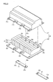
Fig. 3 is a schematic, exploded perspective view of the battery pack and the securing member in the first embodiment of the present invention. -
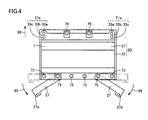
Fig. 4 is a schematic plan view of the battery pack and the securing member in the first embodiment of the present invention. -
Fig. 5 is a second schematic cross section of the portion of the battery pack in the first embodiment of the present invention. -
Fig. 6 is an exploded, schematic perspective view of a support member for supporting the battery pack in the first embodiment of the present invention. -
Fig. 7 is a first schematic cross section of the portion of the battery pack in the first embodiment when physical impact is experienced in the vehicular body's longitudinal direction. -
Fig. 8 is a second schematic cross section of the portion of the battery pack in the first embodiment when physical impact is experienced in the vehicular body's longitudinal direction. -
Fig. 9 is an enlarged schematic plan view of another screw hole receiving a screw securing the electricity storage pack to the support member in the first embodiment. -
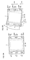
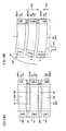
Fig. 10 is a schematic cross section of the portion of a battery pack in a second embodiment of the present invention. -
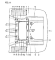
Fig. 11 is a schematic cross section of a battery pack mounted in a vehicular body in a third embodiment of the present invention. -
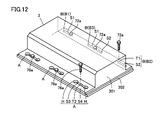
Fig. 12 is a schematic perspective view of the battery pack in the third embodiment of the present invention. -
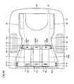
Fig. 13A and Fig. 13B are schematic views for illustrating the battery pack rotationally deforming when it receives physical impact in the third embodiment. -
Fig. 14A and Fig. 14B are schematic views for illustrating the battery pack in the third embodiment rotationally deforming when it receives physical impact. -
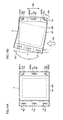
Fig. 15 is a schematic cross section of a battery pack mounted in a vehicular body in a fourth embodiment of the present invention. -
Fig. 16 is a schematic cross section of the battery pack mounted in the vehicular body in the fourth embodiment of the present invention. -
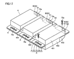
Fig. 17 is a schematic perspective view of the battery pack in the fourth embodiment of the present invention. -
Fig. 18A and Fig. 18B are schematic views for illustrating the battery pack in the fourth embodiment rotationally deforming when it receives physical impact. - Reference will now be made to
Fig. 1 to Fig. 9 to describe a structure mounting an electricity storage pack on a vehicle in a first embodiment of the present invention. - A secondary battery, a capacitor or similar electricity storage equipment is accommodated in a case and thus mounted in a vehicle. In the present invention, equipment including the case and the electricity storage equipment accommodated in the case will be referred to as an electricity storage pack. The electricity storage pack may include other internal components including such as a cooling device such as a cooling duct, a cooling fan and the like for cooling the electricity storage equipment, electronics converting power, and the like.
-
Fig. 1 is a schematic cross section of the portion of the battery pack in the present embodiment.Fig. 1 shows a rear portion of a vehicular body. In the present invention a so-called sedan vehicle will be described. The vehicle includes abody 61.Body 61 is formed to be generally a quadrangle when it is seen in a plane.Body 61 has arear surface 61a. The vehicular body has a rear portion having arear wheel 60. - In the present embodiment the electricity storage pack implemented as a
battery pack 1 is disposed in the vehicular body at a rear portion.Battery pack 1 is disposed in a trunk room.Battery pack 1 includes a case implemented as abattery case 20.Battery case 20 internally accommodates electricity storage equipment implemented as a storage battery. While the present embodiment providesbattery case 20 formed of iron, the electricity storage equipment's case may be formed of any material. - In the present embodiment the vehicle includes a support member formed to support
battery pack 1. The support member includes a side member (or side frame) 50.Side member 50 configures a portion of the main body of the vehicular body.Side member 50 is disposed in the vehicular body at opposite sides as seen in the vehicular body's widthwise direction.Side member 50 extends in the vehicular body's longitudinal direction. -
Battery pack 1 has a front end supported byside member 50 via amount 55 and afloor member 52.Battery pack 1 has a rear end supported byside member 50 via arear bracket 27, amount 56 andfloor member 52. -
Side member 50 has an upper surface withfloor member 52 disposed thereon.Floor member 52 is formed in the form of a plate.Floor member 52 is disposed to straddle a portion betweenside members 50 disposed in the vehicular body at the opposite sides as seen in the vehicular body's widthwise direction.Mounts floor member 52. - In the present embodiment the vehicle includes
rear bracket 27 as a securing member for securingbattery pack 1 toside member 50.Rear bracket 27 is coupled to mount 56 with a screw implemented as abolt 71.Mount 56 is secured toside member 50.Rear bracket 27 is coupled tobattery pack 1 with abolt 72. In the present embodimentrear bracket 27 is formed of iron. - In the present embodiment
rear bracket 27 is formed to have a longitudinal direction.Rear bracket 27 is formed in the form of a plate.Rear bracket 27 is coupled tobattery pack 1 at a rear end at opposite sides as seen in the widthwise direction.Rear bracket 27 is coupled to have its longitudinal direction substantially parallel to the vehicular body's widthwise direction. -
Battery pack 1 has a front end connected to mount 55 with abolt 75.Mount 55 extends in the vehicular body's widthwise direction.Mount 55 is formed to bridge twoside members 50.Mount 55 is secured toside member 50 with abolt 74. -
Fig. 2 is a schematic perspective view of the battery pack and the rear bracket in the present embodiment.Fig. 3 shows an exploded perspective view of the battery pack and the rear bracket in the present embodiment. Thebattery pack 1battery case 20 is in the form of a box.Battery case 20 includes anupper case 21 and alower case 22.Rear bracket 27 has an outer end with ascrew hole 27a.Rear bracket 27 has an inner end with ascrew hole 27b. -
Lower case 22 has an upper surface, on which electricity storage equipment implemented as astorage battery 25 is disposed. In the present embodiment,storage battery 25 includes a plurality ofbattery cells 25a.Battery cells 25a are stacked in layers.Upper case 21 coversstorage battery 25. - With reference to
Fig. 1 to Fig. 3 ,upper case 21 has a front end withscrew holes Lower case 22 has a front end withscrew holes Screw hole 21a and screwhole 22a have their respective positions to correspond to each other.Screw hole 21b andscrew hole 22b have their respective positions to correspond to each other. Screwholes bolt 76 to fastenupper case 21 andlower case 22 together. Furthermore, screwholes bolt 75 to couplebattery pack 1 to mount 55. -
Lower case 22 has a rear end withscrew holes Upper case 21 has a rear end having screw holes formed to correspond to screwholes Screw hole 22c and a screw hole ofupper case 21 that corresponds thereto receive abolt 73 to fastenupper case 21 andlower case 22 together. Furthermore,screw hole 22d, a screw hole ofupper case 21 that corresponds thereto, and therear bracket 27screw hole 27b receivesbolt 72 to fastenupper case 21 andlower case 22 together and also couplerear bracket 27 tobattery case 20. -
Fig. 4 is a schematic plan view of the battery pack and the rear bracket in the present embodiment. Anarrow 89 indicates the vehicular body's front side.Upper case 21 andlower case 22 are fastened to each other withbolts Rear bracket 27 is coupled tobattery pack 1 withbolt 72.Rear bracket 27 is coupled pivotably aroundbolt 72 serving as an axis of pivotation, as indicated byarrow 85. - Furthermore, in the present embodiment, with reference to
Fig. 1 ,rear bracket 27 has an outer side coupled toside member 50 pivotably.Rear bracket 27 is connected to mount 56 pivotably aroundbolt 71 serving as an axis of pivotation. Thus in the present embodimentrear bracket 27 has one side coupled tobattery pack 1 pivotably and the other side coupled toside member 50 pivotably. - With reference to
Fig. 3 andFig. 4 , at a front end ofbattery pack 1 at opposite sides as seen in the widthwise direction,upper case 21 hasscrew hole 21a andlower case 22 hasscrew hole 22a. Screw holes 21 a, 22a have a longitudinal direction.Screw holes Screw hole 21 a formed inupper case 21 andscrew hole 22a formed inlower case 22 are substantially identical in geometry. - In the present
embodiment screw holes round portion 3 3 a and arear round portion 33c communicating through acommunication portion 33b.Front round portion 33a andrear round portion 33c are formed to have a diameter larger than a bolt's shank.Communication portion 33b is formed to have a width smaller than the bolt's shank. Before physical impact is received,screw 75 is located inrear round portion 33c (seeFig. 1 ). -
Fig. 5 is a second schematic cross section of a structure mounting a battery pack on a vehicle in the present embodiment.Fig. 5 is a schematic cross section provided when the vehicular body is cut along a plane extending in a vertical direction. Behind a rear seat 62 apartition panel 63 is disposed.Partition panel 63 partitions the cabin and the trunk room. In the presentembodiment battery pack 1 is disposed in the trunk room. -
Side member 50 has a kick upportion 50a formed to swell upward.Battery pack 1 is disposed at kick upportion 50a.Mounts arrow 88a.Arrow 88a indicates a length extending along an upper surface ofside member 50.Battery pack 1 is supported to be substantially horizontal when it is seen sideways. -
Fig. 6 is a schematic, exploded perspective view of the support member in the present embodiment. In the present embodiment the support member includesside member 50, across member 51 andfloor member 52.Cross member 51 securesside members 50 together.Floor member 52 is disposed on an upper surface ofside member 50 and that ofcross member 51. - In the present embodiment the support member includes
mounts Mounts floor member 52. In the present embodiment,side member 50 is welded and thus secured to crossmember 51.Floor member 52 is welded and thus secured toside member 50.Mounts floor member 52. -
Fig. 7 is a first schematic cross section of the vehicle of the present embodiment receiving a longitudinal physical impact.Fig. 7 is a view corresponding toFig. 5 . For example, if the longitudinal physical impact is received by the vehicular body at a rear portion as it is bumped by another vehicular body from behind, then, as indicated by anarrow 86, the vehicular body longitudinally receives a load. Theside member 50 kick upportion 50a, curved upward, is further curved, as indicated by anarrow 87. At the time, a distance betweenmount 55 andmount 56, as indicated by anarrow 88b, is increased to be larger than that before the vehicle is bumped from behind. In the presentembodiment battery case 20 deforms at the time. -
Fig. 8 is a second schematic cross section of the vehicle of the present embodiment receiving a longitudinal physical impact. For example when the vehicle is bumped at the back,rear bracket 27 disposed behindbattery pack 1 pivots.Rear bracket 27 has its lengthwise direction diverted from a position substantially parallel to the vehicular body's widthwise direction.Bolt 72 supportingrear bracket 27 positionally shifts relatively more forward thanbolt 71 supportingrear bracket 27. - At the front side of
battery pack 1, bolt 75 moves inscrew hole 2 1 a to frontround portion 33a. More specifically, thebolt 75 shank moves fromrear round portion 33c to frontround portion 33a. In doing so, bolt 75 spreadscommunication portion 33b connecting front andrear round portions - Thus the present embodiment provides a structure mounting an electricity storage pack on a vehicle, that allows the electricity storage pack to be supported in a manner varying to reduce damage to the electricity storage pack. In particular, the structure can prevent the electricity storage pack from coming off a support member.
- While the above describes that a support member supporting an electricity storage pack is deformed by way of example, a similar effect can also be obtained when the electricity storage pack directly receives physical impact. For example, if the electricity storage pack is disposed in the trunk room, and the vehicle for example bumps into a preceding vehicle and a load placed in the trunk room collides directly against the electricity storage pack, the securing member can pivot to reduce damage to the electricity storage pack.
- In the present embodiment the electricity storage pack is disposed in a vehicular body at a rear portion. This configuration can effectively reduce or prevent damage to the electricity storage pack when the vehicular body receives physical impact from behind. The vehicular body would receive physical impact mainly when it has collision at the front or the back. As well as vehicles bumping into each other, erroneous driving operation or the like would also cause the vehicle to crash into a building. Depositing the electricity storage pack in a vehicle at a front or rear portion that is an end portion as seen in a direction in which the vehicle travels renders the present invention's effect remarkable. If the electricity storage pack is disposed in the vehicular body at the front portion, the electricity storage pack is disposed for example in the engine room.
- The present embodiment provides a securing member implemented as a bracket having a longitudinal direction substantially parallel to the vehicular body's widthwise direction. This configuration allows the securing member to efficiently pivot when the vehicular body receives longitudinal physical impact.
- Furthermore in the present embodiment the battery pack has one end secured to a mount with a screw inserted into
screw hole 21 a (seeFig. 4 ) extending in the vehicle's longitudinal direction. Thus, when the electricity storage pack receives a load, the electricity storage pack can have one end moved relative to the screw to accommodate the support member's deformation. - While the electricity storage pack has a front end with a screw hole in the form of an elongate hole having a longitudinal direction, the screw hole is not limited thereto, and may for example be a round screw hole as seen in a plane. Furthermore, as will be described later, the screw hole may be surrounded by a thin portion.
- While in the present embodiment a pivotably coupled securing member is coupled to an electricity storage pack at a rear side thereof, it is not limited thereto and may be disposed at any side. For example, if it is assumed that a load is exerted in a lateral direction of the vehicular body, the securing member may be disposed in the lateral direction of the vehicular body.
-
Fig. 9 is an enlarged schematic plan view of a screw hole of another electricity storage pack in the present embodiment. This electricity storage pack has anupper case 31.Upper case 31 has ascrew hole 31a.Screw hole 31a is a portion corresponding in theFig. 4 upper case 21 to screwhole 21a.Screw hole 31a is formed to be substantially round as seen in a plane. -
Screw hole 31a is surrounded by athin portion 31b.Thin portion 31b is formed to be smaller in thickness than a portion outer than and surroundingthin portion 31b.Thin portion 31b has a longitudinal direction.Thin portion 31b extends in the vehicular body's longitudinal direction.Thin portion 31b is provided forwardly ofscrew hole 31a. A lower case is also similarly configured. More specifically, the upper and lower cases have their respective screw holes surrounded by thin portions, respectively. - A screw hole receiving a screw securing the electricity storage pack to the support member that is surrounded by a thin portion allows the screw's shank in the screw hole to move when the vehicular body receives physical impact. This tears
thin portion 3 1b and thus allows the electricity storage pack to follow the support member's deformation. Alternatively the physical impact's energy can be absorbed as the screw's shank travelsthin portion 31b. - While in the present embodiment the electricity storage pack has a case formed to be deformable, it is not limited thereto. In addition to the case, the securing member implemented as a bracket may also be formed to be deformable. The securing member can be formed of any material.
- With reference to
Fig. 10 , the present invention in a second embodiment provides a structure mounting an electricity storage pack on a vehicle, as will be described hereinafter. The present embodiment provides a structure mounting an electricity storage pack on a vehicle, that supports the electricity storage pack's front portion by a structure different from that described in the first embodiment. -
Fig. 10 is a schematic cross section of a structure mounting a battery pack on a vehicle in the present embodiment. In the present embodiment the structure mounting a battery pack on a vehicle employs four securing members to secure a battery pack to a support member. - The structure mounting a battery pack on a vehicle includes a securing member implemented as a
front bracket 45 disposed at a front end of abattery pack 2.Battery pack 2 includes anupper case 41 and alower case 42.Upper case 41 andlower case 42 are fastened together bybolts -
Front bracket 45 is pivotably coupled tolower case 42 with abolt 79.Front bracket 45 is pivotably coupled to amount 46 with abolt 78.Mount 46 is each disposed at opposite sides as seen in the widthwise direction, and secured toside member 50. - Thus a pivotable securing member can be disposed at an end, as seen in a direction in which it is assumed that the vehicular body receives physical impact, to alone support the electricity storage pack to also reduce or prevent damage to the electricity storage pack against large physical impact. For example it can ensure less or no damage to the electricity storage pack for example when the support member significantly deforms.
- The remainder in configuration, and function and effect is similar to that of the structure mounting an electricity storage pack on a vehicle in the first embodiment. Accordingly it will not be described repeatedly. Furthermore, in the above described figures, identical or corresponding components are identically denoted.
- With reference to
Fig. 11 to Fig. 14B , the present invention in a third embodiment provides a structure mounting (or attaching) an electricity storage pack to a vehicle, as will be described hereinafter. - With reference to
Fig. 11 , the present embodiment provides a structure mounting an electricity storage pack on a vehicle, that has an electricity storage pack implemented as abattery pack 3 having an end closer to the front side of the vehicular body that is supported byside member 50 viamount 55 andfloor member 52, and an end closer to the rear side of the vehicular body that is supported byside member 50 via amount 56a andfloor member 52, rather thanrear bracket 27 described in the first embodiment. The remainder in configuration similar to that of the first embodiment will be identically labeled and will not be described repeatedly. - The present embodiment provides
battery pack 3 including anupper case 301 and alower case 302. Similarly as has been described in the first embodiment, on an upper surface oflower case 302 is disposed electricity storage equipment implemented as astorage battery 25 including a plurality ofbattery cells 25a stacked in layers, andupper case 301 coversstorage battery 25.Upper case 301 andlower case 302 each have ends closer to the front and rear sides, respectively, of the vehicular body that have attachment portions A, B (B1, B2, B3) receivingbolts battery pack 3 to the support member implemented asmount 55 andmount 56a. Furthermore,upper case 301 andlower case 302 are also fastened together.Upper case 301 andlower case 302 are configured of aluminum metal or a similar material. - As shown in
Fig. 12 , attachment portion A includes an attachment hole T2 receiving the shank ofbolt 76a, slits S3 and S4 extending inbattery pack 3 in a widthwise direction of the vehicular body, and a disengagement hole H having a diameter larger than the head ofbolt 76a. Slits S3, S4 are elongate holes adjacent to attachment holeT2 receiving bolt 76a, such that they are opposite to each other in the widthwise direction of the vehicular body to sandwich attachment hole T2, and couple attachment hole T2 and disengagement hole H together. Furthermore, in the present embodiment, attachment portion A is provided in the end portion ofbattery pack 3 closer to the front side of the vehicular body, at three attachment positions, and slits S3, S4 are equal in length. - Attachment portion B is provided in the end portion of
battery pack 3 closer to the rear side of the vehicular body at three attachment positions and includes an attachment hole T1 receiving the shank ofbolt 72a and aslit S 1 or/and S2 extending inbattery pack 3 in the widthwise direction of the vehicular body. As shown inFig. 11 andFig. 12 , of three attachment portions B, an attachment portion B 1 (or a first attachment portion) includes aslit S 1 coupled to attachment hole T1 and extending rightward (inFig. 11 , upward) in the widthwise direction of the vehicular body. An attachment portion B2 (a second attachment portion) includes a slit S2 that couples toattachment hole T 1 distant fromattachment portion B 1 and extends leftward (inFig. 11 , downward) in the widthwise direction of the vehicular body and hence in a direction opposite to that in which slitS 1 extends. An attachment portion B3 is located between attachment portion B1 and attachment portion B3 and includes slitS 1 and slit S2 adjacent to attachment hole T1 opposite as seen in the widthwise direction of the vehicular body. - Thus
attachment portion B 1 has slitS 1 formed to be an elongate hole that allowsbattery pack 3 receiving physical impact at a side closer toattachment portion B 1 to displace (or deform) toward attachment portion B2 and does not allowbattery pack 3 receiving physical impact at a side closer to attachment portion B2 to displace toward attachment portion B1, and attachment portion B2 also has slit S2 formed to be an elongate hole that allowsbattery pack 3 receiving physical impact at a side closer to attachment portion B2 to displace toward attachment portion B1 and does not allowbattery pack 3 receiving physical impact at a side closer toattachment portion B 1 to displace toward attachment portion B2. - Furthermore the elongate holes of slits S1 and S2 of attachment portion B are larger in length than those of slits S3 and S4 of attachment portion A, as seen in their lengthwise direction, and slits S1-S4 have their lengthwise direction substantially parallel to a direction in which the vehicular body or
battery pack 3 receives physical impact. - In the present
embodiment battery pack 3 is secured to a support member at attachment portions A, B having attachment portion A provided with disengagement hole H having a diameter larger than the head ofbolt 76a for disengaging the support member andbattery pack 3 secured together at attachment portion A, and attachment portion B including first attachment portion B1 and second attachment portion B2 distant from each other. When physical impact is received at a side closer to firstattachment portion B 1 or that closer to second attachment portion B2,battery pack 3 can be disengaged from the support member at attachment portion A, andbattery pack 3 as described above, i.e.,battery pack 3 accommodating an electricity storage device implemented asstorage battery 25, can haveupper case 301 andlower case 302 deformed such that the cases pivot around firstattachment portion B 1 or second attachment portion B2 that is opposite to that receiving the physical impact (and that end ofbattery pack 3 which has attachment portion A acts as a free end). Thus the physical impact can be absorbed and dispersed andbattery pack 3 can suitably be protected. - Furthermore, as shown in
Fig. 11 , while the present embodiment assumes that a vehicular body receives physical impact laterally or in a widthwise direction of the vehicular body relative to a longitudinal direction of the vehicular body, i.e., that a vehicle is bumped sideways, andbattery pack 3 thus receives a load of physical impactive force, the structure mounting an electricity storage pack on a vehicle in the present embodiment is applicable to physical impact or collision acting onbattery pack 3 in a direction substantially parallel to that in which the elongate holes of the slits of attachment portions A and B have their respective lengthwise directions, and it is also applicable to a load of physical impactive force exerted onbattery pack 3 in the longitudinal direction of the vehicular body if attachment portions A, B and their slits' lengthwise directions are modified to accommodate the physical impact exerted in the longitudinal direction of the vehicular body. - Reference will now be made to
Fig. 13A and Fig. 13B to describe howbattery pack 3 of the present embodiment behaves when it receives physical impact. Anarrow 501 indicates a direction in which the physical impact is exerted. Anarrow 502 indicates howbattery pack 3 deforms. Anarrow 503 indicates howbattery pack 3 slides. Anarrow 504 indicates howbattery pack 3 slidingly and compressively deforms. - If in the
Fig. 13A condition the vehicular body orbattery pack 3 receives physical impact in the widthwise direction of the vehicular body at a side closer to attachment portion B2, then, as shown inFig. 13B ,battery pack 3 elastically and plastically deforms and thus displaces (or deforms) in a direction in which the physical impactive force acts. Asbattery pack 3 displaces, the shank ofattachment bolt 76a in attachment portion A passes through slit S4 and thus reaches disengagement hole H. This causes a physical impact causing the head ofattachment bolt 76a to come off disengagement hole H, and mount 55 andbattery pack 3 at attachment portion A are disengaged (or the force ofbolt 76a fastening mount 55 andbattery pack 3 together is released). - At attachment portion B, on the other hand, while
battery pack 3 as a whole displaces rightward (in the figure, upward), theattachment portion B 1slit S 1 does not allow the physical impact received from the side closer to attachment portion B2 to displacebattery pack 3 rightward (in the figure, upward) and the attachment portions B2 and B3 slits S2 allow the physical impact received from the side closer to attachment portion B2 to displacebattery pack 3 rightward (in the figure, upward), as has been described above, andupper case 301 and lower case 302 (compressively) deform in a vicinity of attachment portion B2 and attachment portion B3 to allowbattery pack 3 to displace rightward (in the figure, upward). - Thus, as shown in
Fig. 13B , whenbattery pack 3 receives physical impact at the side closer to second attachment portion B2, attachment portion A comes offmount 55 andattachment portion B 1 preventsbattery pack 3 from moving toward attachment portion B1.Battery pack 3 pivots aroundbolt 72a of attachment portion B1, whilebattery pack 3 deforms, and thus absorbs and disperses the physical impact. Asattachment portion B 1 preventsbattery pack 3 from moving toward attachment portion B1,battery pack 3 does not entirely displace toward attachment portion B1. Rather,battery pack 3 deforms such that it pivots aroundbolt 72a of attachment portion B1, andupper case 301 andlower case 302 compressively deform (or compressively displace) in a vicinity of attachment portion B2 and attachment portion B3. - In the present embodiment when the vehicular body or
battery pack 3 receives physical impact at attachment portion B2 the structure mounting an electricity storage pack on a vehicle allowsbattery pack 3 to displace as it deforms gradually such that it pivots aroundbolt 72a of attachment portion B1, i.e., an attachment portion opposite to attachment portion B2 receiving the physical impact. This can appropriately absorb and disperse energy with respect to physical impact and hence prevent physical impact from excessively deformingbattery pack 3. Note that when physical impact deformsbattery pack 3, the second attachment portion implemented as attachment portion B2 may come off the support member. More specifically, when the second attachment portion implemented as attachment portion B2 comes off the support member,battery pack 3 having plastically deformed has sufficiently absorbed physical impact. Accordingly, attachment portion B2 may be configured to come off the support member beforeupper case 301 andlower case 302 rapture as they plastically deform. - Furthermore, the attachment portion B slits
S 1 and S2 each have an elongate hole having in its lengthwise direction a length larger than the attachment portion A slits S3 and S4 each do. This ensures thatbattery pack 3 receiving physical impact and thus displacing displaces slidingly in a direction in which the physical impact acts, until the shank ofattachment bolt 76a in attachment portion A passes through slit S3 or S4 and reaches disengagement hole H and thus causes physical impact causing the head ofattachment bolt 76a to come off disengagement hole H, so that the head ofbolt 76a can readily come off disengagement hole H. Note that slits S3 and S4 may each have an elongate hole having a width larger at portions closer to disengagement hole H than those closer to attachment hole T2 so that the slits can have a width increasing from attachment hole T2 toward disengagement hole H. - Furthermore while
Fig. 11 to Fig. 13B show slits S1-S4 having a lengthwise direction substantially parallel to a direction in which the vehicular body orbattery pack 3 receives physical impact, attachment portion B1 and attachment portion B3 may haveslits S 1 and S2 having a lengthwise direction oblique relative to the direction in which the vehicular body orbattery pack 3 receives physical impact, as shown inFig. 14A and Fig. 14B as slits S1a, S2a. The slits may have a linear geometry or a curved geometry having a curvature. - More specifically, to allow
battery pack 3 to displace while gently deforming such that it pivots aroundbolt 72a of attachment portion B1, i.e., an attachment portion that is opposite to attachment portion B2 receiving physical impact when the vehicular body orbattery pack 3 receives the physical impact at attachment portion B2, slit S1a or S2a may have a lengthwise direction that is perpendicular to a direction in which the vehicular body orbattery pack 3 receives the physical impact and that inclines toward attachment portion A to increase the displaceability ofbattery pack 3 receiving the physical impact (i.e., the displaceability ofbattery pack 3 at attachment portion B2 in the vehicular body's longitudinal direction) and reduce the deformability ofbattery pack 3, and also achieve more appropriate absorption and dispersion of energy with respect to physical impact. - Note that when
battery pack 3 is allowed to displace in a direction perpendicular to that in which the vehicular body orbattery pack 3 receives physical impact, more appropriate absorption and dispersion of energy with respect to the physical impact can be achieved. Accordingly, slitsS 1 and S2 may be formed for example in the letter of T or a cross. - Alternatively, attachment portion A may be configured to dispense with slits S2 and S3 and have disengagement hole H and attachment hole T2 adjacently. Alternatively, attachment portions A, B may dispense with attachment holes T1, T2 receiving the shanks of
bolts bolts - Furthermore, one of
upper case 301 andlower case 302 may have attachment holes A and B and the other of the cases that has no attachment hole may be configured to be secured to that having the attachment holes, and the support member and one of the cases may be secured together. - Furthermore while in the present
embodiment battery pack 3 has ends each having attachment portions at three attachment positions,battery pack 3 may have ends each having attachment portions at at least two positions in view of ensuring thatbattery pack 3 and the support member are firmly secured together. - With reference to
Fig. 15 to Fig. 18B , the present invention in a fourth embodiment provides a structure mounting (or attaching) an electricity storage pack on a vehicle, as will be described hereinafter. - As shown in
Fig. 15 andFig. 16 , the present embodiment provides an electricity storage pack implemented as abattery pack 4 disposed in a vehicular body under a rear seat and having an end closer to a front side of the vehicular body that is supported byside member 50 via amount 55a andfloor member 52, and an end closer to a rear side of the vehicular body that is supported byside member 50 via amount 56a andfloor member 52. The remainder in configuration similar to that described in the first or third embodiment will be denoted identically and will not be described. - In the present
embodiment battery pack 4 includes anupper case 401 and alower case 402, and, as shown inFig. 17 to Fig. 18B , a plurality ofstorage batteries 25 implemented as a battery module BM are disposed at predetermined intervals, with a control unit (a monitoring unit) CU posed therebetween.Upper case 401 is formed to be lower at a portion covering control unit CU than that covering battery module BM, and thus has a recess between battery modules BMs. - Typically under a seat a slide mechanism (or a rail R) is provided to allow the seat to slide. In the present
embodiment battery pack 4 allows rail R projecting from the seat downward to be disposed in the recess (or a rail passing portion 404) that is provided between battery modules BMs and hence in an efficiently utilized space. -
Battery pack 4 includingupper case 401 andlower case 402 thus formed, as well as that in the third embodiment, hasupper case 401 andlower case 402 such that their respective ends closer to the front side of the vehicular body and their respective ends closer to the rear side of the vehicular body have attachment portions A and B (B1, B2, B3) receivingbolt 76a andbolt 72a, respectively.Bolt 76a andbolt 72asecure battery pack 4 to a support member implemented asmount 55a and mount 56a and also fastenupper case 401 andlower case 402 together. Furthermore,upper case 401 andlower case 402 are formed of aluminum metal or a similar material. Furthermore,lower case 402 is provided with an airflow guiding portion 403 for introducing air having flown throughbattery pack 4, and discharging the air outsidebattery pack 4. - With reference to
Fig. 18A and Fig. 18B , in the present embodiment whenbattery pack 4 receives physical impact,battery pack 4 behaves, as will be described hereinafter. Anarrow 501 indicates a direction in which the physical impact is exerted. Anarrow 502 indicates howbattery pack 3 deforms. Anarrow 503 indicates howbattery pack 3 slides. Anarrow 505 indicates howbattery pack 3 slidingly and compressively deforms. - If in the
Fig. 18A condition the vehicular body orbattery pack 4 receives physical impact in the widthwise direction of the vehicular body at a side closer to attachment portion B2, then, as shown inFig. 18B ,battery pack 4 elastically and plastically deforms and thus displaces in a direction in which the physical impactive force acts. Asbattery pack 4 displaces, the shank ofattachment bolt 76a in attachment portion A passes through slit S4 and thus reaches disengagement hole H. This causes a physical impact causing the head ofattachment bolt 76a to come off disengagement hole H, and mount 55 andbattery pack 3 at attachment portion A are disengaged (or released) from each other. - At attachment portion B, on the other hand, while
battery pack 4 displaces rightward (in the figure, upward), theattachment portion B 1slit S 1 does not allow the physical impact received from the side closer to attachment portion B2 to displacebattery pack 4 rightward (in the figure, upward) and the attachment portions B2 and B3 slits S2 allow the physical impact received from the side closer to attachment portion B2 to displacebattery pack 4 rightward (in the figure, upward), as has been described above, andupper case 401 and lower case 402 (compressively) deform in a vicinity of attachment portion B2 and attachment portion B3 to allowbattery pack 4 to (compressively) displace rightward (in the figure, upward). - Thus, similarly as described in the third embodiment,
battery pack 4 deforms while pivoting aroundbolt 72a ofattachment portion B 1 disallowingbattery pack 4 to displace rightward (in the figure, upward) and thus absorbs and disperses physical impact, and in the present embodiment,upper case 401 andlower case 402 related torail passing portion 404 located between battery modules BMs (compressively) deform to be sandwiched between battery modules BMs, and thus absorb physical impact. - This can reduce in comparison with the third embodiment the displaceability of
battery pack 4 pivoting aroundbolt 72a ofattachment portion B 1 opposite to attachment portion B2 receiving physical impact when the vehicular body orbattery pack 4 receives the physical impact at attachment portion B2, and it also allows sufficient absorption and dispersion of energy with respect to the physical impact. This can preventbattery pack 4 from excessively deforming, and also preventbattery pack 4 from colliding against other members, components or the vehicular body whenbattery pack 4 deforms. - The third and fourth embodiments have been described with an electricity storage pack provided with attachment portions A, B by way of example. Alternatively, for example, attachment portions A, B may be provided to mount 55a (55b) and
mount 56a (56b). In that case, the electricity storage pack is configured of upper and lower cases that do not have a disengagement hole or a slit. This can reduce the cost for producing the cases and prevent an attachment portion from having reduced strength. - Furthermore in the third and fourth embodiments the support member and the electricity storage pack are bolted together. Alternatively, for example, they may be fitted or engaged together by a recess and a projection, a protrusion, a hook, or the like, and thus secured together.
- The present invention can thus provide a structure mounting an electricity storage pack on a vehicle that can reduce or prevent damage to the electricity storage pack when the vehicular body or the electricity storage pack receives physical impact.
- It should be understood that the embodiments disclosed herein are illustrative and non-restrictive in any respect. The scope of the present invention is defined by the terms of the claims, rather than the description above, and is intended to include any modifications within the scope and meaning equivalent to the terms of the claims.
- The present invention is advantageously applicable to electricity storage packs mounted on automobiles.
Claims (14)
- A structure mounting an electricity storage pack on a vehicle, comprising:a support member (50, 55, 56) formed to support said electricity storage pack (1, 2); anda securing member (27, 45) securing said electricity storage pack (1, 2) to said support member (50, 55, 56), said securing member (27, 45) having one side pivotably coupled to said electricity storage pack (1, 2) and the other side pivotably coupled to said support member (50, 55, 56).
- The structure mounting an electricity storage pack on a vehicle according to claim 1, wherein said electricity storage pack (1, 2) is disposed in a vehicular body (61) at one of a rear portion and a front portion.
- The structure mounting an electricity storage pack on a vehicle according to claim 1, wherein:said securing member (27, 45) is formed to have a longitudinal direction; andsaid securing member (27, 45) has said longitudinal direction substantially parallel to a widthwise direction of a vehicular body (61).
- The structure mounting an electricity storage pack on a vehicle according to claim 1, wherein:said electricity storage pack (1, 2) has one of a front end and a rear end supported by said support member (50, 55, 56) via said securing member (27, 45);said electricity storage pack (1, 2) has the other end secured to said support member (50, 55, 56) with a screw (75);said electricity storage pack (1, 2) has a screw hole (31 a) formed to receive said screw (75);said electricity storage pack (1, 2) has a thin portion (31b) surrounding said screw hole (31 a); andsaid thin portion (31b) is formed to be thinner than a portion surrounding said thin portion (31b).
- The structure mounting an electricity storage pack on a vehicle according to claim 1, wherein:said electricity storage pack (1, 2) has one of a front end and a rear end supported by said support member (50, 55, 56) via said securing member (27, 45);said electricity storage pack (1, 2) has the other end secured to said support member (50, 55, 56) with a screw (75);said electricity storage pack (1, 2) has a screw hole (21 a, 22a) formed to receive said screw (75); andsaid screw hole (21a, 22a) is formed to extend in a longitudinal direction of a vehicular body (61).
- A structure mounting an electricity storage pack on a vehicle, said electricity storage pack being secured to a support member (50, 55, 55a, 56a) by an attachment portion (A, B) provided at each of one and the other ends of said electricity storage pack (3, 4) accommodating electricity storage equipment (25) therein, wherein:one said attachment portion (A) has a disengagement portion (H) for disengaging said support member (55, 55a) and said electricity storage pack (3, 4) secured together at said one attachment portion (A), and the other said attachment portion (B) includes a first attachment portion (B1) and a second attachment portion (B2) distant from each other; andwhen physical impact is received at one of said first attachment portion (B1) and said second attachment portion (B2), said electricity storage pack (3, 4) is disengaged from said support member (55, 55a) at said one attachment portion (A) and deforms as said electricity storage pack (3, 4) pivots around one of said first attachment portion (B1) and said second attachment portion (B2) opposite to that receiving the physical impact.
- The structure mounting an electricity storage pack on a vehicle according to claim 6, wherein said first attachment portion (B1) includes a slit portion (S1) allowing said electricity storage pack (3, 4) to move toward said second attachment portion (B2) when physical impact is received.
- The structure mounting an electricity storage pack on a vehicle according to claim 6, wherein said second attachment portion (B2) includes a slit portion (S2) allowing said electricity storage pack (3, 4) to move toward said first attachment portion (B1) when physical impact is received.
- The structure mounting an electricity storage pack on a vehicle according to claim 6, wherein said electricity storage pack (3, 4) is secured to said support member (50, 55, 55a, 56a) by said one and other attachment portions (A, B) with an attachment bolt (72a, 76a), and said disengagement portion (H) has a disengagement hole larger than a head of said attachment bolt (76a).
- The structure mounting an electricity storage pack on a vehicle according to claim 9, wherein said one attachment portion (A) has a slit portion (S3, S4) allowing said electricity storage pack (3, 4) to move toward one of said first attachment portion (B1) and said second attachment portion (B2) when physical impact is received, and said slit portion (S3, S4) has an end having said disengagement portion (H).
- The structure mounting an electricity storage pack on a vehicle according to claim 10, wherein said slit portion (S1, S2) of said first and second attachment portions (B 1, B2) of said other attachment portion (B) is larger in length than said slit portion (S3, S4) of said one attachment portion (A).
- The structure mounting an electricity storage pack on a vehicle according to claim 7 or 8, wherein said slit portion (S1-S4) has a lengthwise direction substantially parallel to a direction in which one of a vehicular body (61) and said electricity storage pack (3, 4) receives physical impact.
- The structure mounting an electricity storage pack on a vehicle according to claim 7 or 8, wherein said first and second attachment portions (A, B) have a slit portion (S1a, S2a) having a lengthwise direction oblique with respect to a direction in which one of a vehicular body (61) and said electricity storage pack (3, 4) receives physical impact.
- A structure mounting an electricity storage pack on a vehicle, said electricity storage pack being secured to a support member (50, 55, 55a, 56a) and accommodating electricity storage equipment (25) therein, wherein:said support member (50, 55, 55a, 56a) includes an attachment portion for securing said electricity storage pack (3, 4) at one and the other ends to said support member (50, 55, 55a, 56a);one said attachment portion has a disengagement portion for disengaging said support member (50, 55, 55a, 56a) and said electricity storage pack (3, 4) secured together at said one attachment portion, and the other said attachment portion is configured of a first attachment portion and a second attachment portion distant from each other; andwhen physical impact is received at one of said first attachment portion and said second attachment portion, said support member (50, 55, 55a, 56a) is disengaged from said electricity storage pack (3, 4) at said one attachment portion to allow said electricity storage pack (3, 4) to pivot around one of said first attachment portion and said second attachment portion opposite to that receiving the physical impact and thus deform.
Priority Applications (1)
| Application Number | Priority Date | Filing Date | Title |
|---|---|---|---|
| EP09005981.7A EP2095985B1 (en) | 2006-02-27 | 2007-02-23 | Structure mounting an electricity storage pack on a vehicle |
Applications Claiming Priority (3)
| Application Number | Priority Date | Filing Date | Title |
|---|---|---|---|
| JP2006050695 | 2006-02-27 | ||
| JP2007023587A JP5141026B2 (en) | 2006-02-27 | 2007-02-01 | In-vehicle structure of power storage pack |
| PCT/JP2007/053990 WO2007100072A1 (en) | 2006-02-27 | 2007-02-23 | Structure for mounting electricity storage pack on vehicle |
Related Child Applications (1)
| Application Number | Title | Priority Date | Filing Date |
|---|---|---|---|
| EP09005981.7A Division EP2095985B1 (en) | 2006-02-27 | 2007-02-23 | Structure mounting an electricity storage pack on a vehicle |
Publications (2)
| Publication Number | Publication Date |
|---|---|
| EP1992513A1 true EP1992513A1 (en) | 2008-11-19 |
| EP1992513A4 EP1992513A4 (en) | 2009-03-11 |
Family
ID=38459167
Family Applications (2)
| Application Number | Title | Priority Date | Filing Date |
|---|---|---|---|
| EP09005981.7A Expired - Fee Related EP2095985B1 (en) | 2006-02-27 | 2007-02-23 | Structure mounting an electricity storage pack on a vehicle |
| EP07715140A Withdrawn EP1992513A4 (en) | 2006-02-27 | 2007-02-23 | Structure for mounting electricity storage pack on vehicle |
Family Applications Before (1)
| Application Number | Title | Priority Date | Filing Date |
|---|---|---|---|
| EP09005981.7A Expired - Fee Related EP2095985B1 (en) | 2006-02-27 | 2007-02-23 | Structure mounting an electricity storage pack on a vehicle |
Country Status (6)
| Country | Link |
|---|---|
| US (1) | US8051934B2 (en) |
| EP (2) | EP2095985B1 (en) |
| JP (1) | JP5141026B2 (en) |
| CN (1) | CN101389501B (en) |
| CA (1) | CA2642003C (en) |
| WO (1) | WO2007100072A1 (en) |
Cited By (14)
| Publication number | Priority date | Publication date | Assignee | Title |
|---|---|---|---|---|
| GB2464370A (en) * | 2008-10-18 | 2010-04-21 | Porsche Ag | Vehicle body |
| WO2012045408A1 (en) * | 2010-10-09 | 2012-04-12 | Audi Ag | Vehicle comprising a traction battery which can absorb crash energy |
| EP2440419A1 (en) * | 2009-06-11 | 2012-04-18 | Nissan Motor Co., Ltd. | Vehicle body structure |
| DE102011002650A1 (en) | 2011-01-13 | 2012-07-19 | Ford Global Technologies, Llc | motor vehicle |
| FR2979078A1 (en) * | 2011-08-17 | 2013-02-22 | Peugeot Citroen Automobiles Sa | Vehicle e.g. hybrid car, battery protecting device, has indexing pin plastically deforming opening in response to impact whose intensity exceeds predetermined value to move support element with respect to another support element |
| WO2013155106A1 (en) * | 2012-04-10 | 2013-10-17 | Toyota Motor Engineering & Manufacturing North America, Inc. | Vehicle construction method to prevent battery damage during rear impact using optimized bracket separation |
| DE102013218811A1 (en) | 2013-09-19 | 2015-03-19 | Volkswagen Aktiengesellschaft | Arrangement for mounting at least one, arranged in a receiving device drive energy storage in a motor vehicle |
| US9172071B2 (en) | 2010-09-16 | 2015-10-27 | Gs Yuasa International Ltd. | Battery pack and electrically powered vehicle provided with same |
| EP3064389A1 (en) * | 2015-03-06 | 2016-09-07 | Toyota Jidosha Kabushiki Kaisha | Battery unit mounting structure |
| EP3287307A1 (en) * | 2016-08-26 | 2018-02-28 | Mitsubishi Jidosha Kogyo K.K. | Electric device mounting structure |
| EP3584854A1 (en) * | 2018-06-20 | 2019-12-25 | Contemporary Amperex Technology Co., Limited | Fixing frame and battery pack |
| EP3678892B1 (en) * | 2017-09-05 | 2022-06-08 | AGCO International GmbH | Agricultural vehicle having electrical drive line |
| SE2150247A1 (en) * | 2021-03-04 | 2022-09-05 | Scania Cv Ab | A battery arrangement for a vehicle, a battery arrangement set and a vehicle |
| WO2022194438A1 (en) * | 2021-03-15 | 2022-09-22 | Psa Automobiles Sa | Housing for a motor vehicle battery |
Families Citing this family (139)
| Publication number | Priority date | Publication date | Assignee | Title |
|---|---|---|---|---|
| JP3708174B2 (en) * | 1994-08-05 | 2005-10-19 | 知彦 服部 | 3D image display device |
| JP4935112B2 (en) | 2006-02-28 | 2012-05-23 | トヨタ自動車株式会社 | In-vehicle structure of power storage pack |
| JP5173182B2 (en) * | 2006-11-13 | 2013-03-27 | トヨタ自動車株式会社 | Power storage unit |
| JP4858203B2 (en) * | 2007-02-07 | 2012-01-18 | トヨタ自動車株式会社 | Car |
| JP4337905B2 (en) * | 2007-04-18 | 2009-09-30 | トヨタ自動車株式会社 | Cooling device for electric equipment mounted on vehicle |
| JP4225363B2 (en) * | 2007-07-24 | 2009-02-18 | トヨタ自動車株式会社 | Vehicle equipped with internal combustion engine and rotating electric machine as power source |
| JP5040566B2 (en) * | 2007-09-28 | 2012-10-03 | 三菱自動車工業株式会社 | Electric vehicle battery fixing structure |
| JP5029263B2 (en) * | 2007-09-28 | 2012-09-19 | 三菱自動車工業株式会社 | Electric car |
| KR20090062380A (en) * | 2007-12-13 | 2009-06-17 | 현대자동차주식회사 | Outlet duct of battery system for hybrid eletric vehicle |
| JP4946969B2 (en) | 2008-05-16 | 2012-06-06 | トヨタ自動車株式会社 | Power supply protection structure |
| GB0811321D0 (en) * | 2008-06-19 | 2008-07-30 | Tennant Scotland Ltd | Cleaning machine |
| US8110300B2 (en) * | 2008-06-30 | 2012-02-07 | Lg Chem, Ltd. | Battery mounting system |
| US8225969B2 (en) * | 2009-03-16 | 2012-07-24 | GM Global Technology Operations LLC | Apparatus for attaching components to a vehicle |
| JP5257718B2 (en) * | 2009-06-05 | 2013-08-07 | トヨタ自動車株式会社 | vehicle |
| JP2010284984A (en) * | 2009-06-09 | 2010-12-24 | Fuji Heavy Ind Ltd | Battery mounting structure for vehicle |
| JP4917631B2 (en) * | 2009-06-29 | 2012-04-18 | アイシン軽金属株式会社 | Vehicle-mounted frame structure for vehicle battery module |
| DE102009031779A1 (en) * | 2009-07-06 | 2011-01-13 | GM Global Technology Operations, Inc., Detroit | Floor structure for a motor vehicle |
| DE102009053138A1 (en) * | 2009-11-05 | 2011-05-12 | Rehau Ag + Co. | Electrically operated vehicle, has battery for storing electricity, and energy absorbing element provided in area directly surrounding battery or battery box for reducing kinetic energy of battery and/or vehicle during accidents |
| US8336657B2 (en) * | 2010-02-12 | 2012-12-25 | Ford Global Technologies, Llc | Support structure for inverter system controller module |
| JP2011227998A (en) * | 2010-04-15 | 2011-11-10 | Toyota Motor Corp | Power supply unit and assembled power supply |
| WO2011148687A1 (en) * | 2010-05-26 | 2011-12-01 | スズキ株式会社 | Structure for vehicle body rear portion |
| JP5156057B2 (en) * | 2010-06-25 | 2013-03-06 | 富士重工業株式会社 | Mounting structure for vehicle battery box |
| CN101947912A (en) * | 2010-08-20 | 2011-01-19 | 重庆长安汽车股份有限公司 | Battery mounting and fixing structure of purely electric automobile |
| DE102010034925A1 (en) * | 2010-08-20 | 2012-02-23 | Gm Global Technology Operations Llc (N.D.Ges.D. Staates Delaware) | Energy storage arrangement in the floor area of a vehicle |
| JP5509011B2 (en) * | 2010-09-16 | 2014-06-04 | 株式会社リチウムエナジージャパン | Battery pack and electric vehicle equipped with the same |
| JP5434860B2 (en) * | 2010-09-17 | 2014-03-05 | トヨタ車体株式会社 | Battery pack mounting structure in vehicle |
| JP5913132B2 (en) | 2010-12-20 | 2016-04-27 | 株式会社Gsユアサ | Electric storage element including a current collector and vehicle including the electric storage element |
| JP5270702B2 (en) * | 2011-02-14 | 2013-08-21 | トヨタ自動車株式会社 | Vehicle equipment mounting structure |
| JP5403290B2 (en) * | 2011-03-31 | 2014-01-29 | 三菱自動車工業株式会社 | Electric vehicle battery mounting structure |
| WO2012157857A2 (en) * | 2011-05-19 | 2012-11-22 | 주식회사 엘지화학 | Battery pack having excellent structural reliability |
| US9472791B2 (en) | 2011-08-11 | 2016-10-18 | Johnson Controls Technology Company | Battery system, housing and vehicle including battery system |
| JP5906689B2 (en) * | 2011-11-22 | 2016-04-20 | トヨタ自動車株式会社 | Vehicle battery mounting structure |
| CN104066609B (en) * | 2012-01-26 | 2015-08-12 | 本田技研工业株式会社 | Fuel-cell vehicle |
| US8813888B2 (en) * | 2012-02-06 | 2014-08-26 | Honda Motor Co., Ltd. | Vehicle body rear structure |
| US20130209857A1 (en) * | 2012-02-15 | 2013-08-15 | GM Global Technology Operations LLC | Battery tray design |
| JP6115011B2 (en) | 2012-02-20 | 2017-04-19 | スズキ株式会社 | Vehicle rear structure |
| DE102012203882B4 (en) * | 2012-03-13 | 2021-03-25 | Bayerische Motoren Werke Aktiengesellschaft | Body of a motor vehicle |
| JP6017539B2 (en) * | 2012-03-29 | 2016-11-02 | 三洋電機株式会社 | Power supply device, vehicle including the same, and power storage device |
| EP2662230B1 (en) * | 2012-05-08 | 2018-01-24 | Magna Steyr Fahrzeugtechnik AG & Co KG | Battery casing |
| US8911892B2 (en) | 2012-05-21 | 2014-12-16 | Lg Chem, Ltd. | Battery module mounting assembly and method for mounting a battery module to a base plate |
| DE102012105140B4 (en) * | 2012-06-14 | 2021-09-09 | Dr. Ing. H.C. F. Porsche Aktiengesellschaft | Motor vehicle with a body shell, a battery module and a device for fastening the battery module to the body shell of the motor vehicle |
| JP6035916B2 (en) * | 2012-07-05 | 2016-11-30 | スズキ株式会社 | Car body rear structure |
| JP2014022277A (en) * | 2012-07-20 | 2014-02-03 | Primearth Ev Energy Co Ltd | Support structure of battery pack, and battery pack |
| JP5935569B2 (en) * | 2012-07-25 | 2016-06-15 | スズキ株式会社 | Battery unit mounting structure for vehicles |
| US9034510B2 (en) | 2012-09-25 | 2015-05-19 | Lg Chem, Ltd. | Battery pack and method of securing a plurality of battery modules in the battery pack |
| EP2909053B1 (en) | 2012-10-19 | 2019-09-25 | Agility Fuel Systems LLC | System and method for mounting a fuel system |
| CN104755296B (en) * | 2012-10-31 | 2017-04-05 | 本田技研工业株式会社 | Electric vehicle |
| US9236592B2 (en) * | 2012-11-27 | 2016-01-12 | Ford Global Technologies, Llc | Protective vehicle battery cage and method of making a battery cage |
| JP6011320B2 (en) * | 2012-12-25 | 2016-10-19 | スズキ株式会社 | Vehicle rear structure |
| US9718362B2 (en) * | 2013-02-20 | 2017-08-01 | Toyota Jidosha Kabushiki Kaisha | Electric vehicle |
| JP5900480B2 (en) * | 2013-05-24 | 2016-04-06 | トヨタ自動車株式会社 | Vehicle battery mounting structure |
| DE102013215436A1 (en) * | 2013-08-06 | 2015-03-05 | Bayerische Motoren Werke Aktiengesellschaft | Device for receiving at least one energy module for a motor vehicle |
| WO2015031900A1 (en) * | 2013-08-30 | 2015-03-05 | King Products, LLC | Battery holder and isolation assembly |
| JP5880509B2 (en) * | 2013-09-25 | 2016-03-09 | トヨタ自動車株式会社 | Vehicle rear structure |
| US9630486B2 (en) * | 2013-12-02 | 2017-04-25 | Honda Motor Co., Ltd. | Vehicle |
| JP5870992B2 (en) * | 2013-12-25 | 2016-03-01 | トヨタ自動車株式会社 | Battery mounting structure for vehicles |
| JP5846193B2 (en) * | 2013-12-25 | 2016-01-20 | トヨタ自動車株式会社 | Battery mounting structure for vehicles |
| JP2015123773A (en) * | 2013-12-25 | 2015-07-06 | トヨタ自動車株式会社 | On-vehicle apparatus mounting structure |
| US9139074B2 (en) | 2014-01-16 | 2015-09-22 | Ford Global Technologies, Llc | Methods and devices for positioning a traction battery on a hybrid or electric vehicle |
| DE102014001289B3 (en) * | 2014-01-31 | 2015-05-13 | Audi Ag | Motor vehicle with structurally integrated battery elements |
| JP5871983B2 (en) * | 2014-03-28 | 2016-03-01 | 富士重工業株式会社 | Battery module protection structure mounted on the rear of the vehicle body |
| DE102014108803A1 (en) * | 2014-06-24 | 2015-12-24 | Dr. Ing. H.C. F. Porsche Aktiengesellschaft | Energy storage for a vehicle and method for providing an energy storage device for a vehicle |
| JP6094548B2 (en) * | 2014-08-29 | 2017-03-15 | 株式会社デンソー | Electronic device housing |
| JP6137105B2 (en) * | 2014-09-30 | 2017-05-31 | トヨタ自動車株式会社 | Battery drive battery mounting structure |
| US9561713B2 (en) * | 2014-12-28 | 2017-02-07 | Skylar Netherland | Systems and methods for a mounting device for vehicles |
| JP6530932B2 (en) * | 2015-03-18 | 2019-06-12 | 本田技研工業株式会社 | vehicle |
| US11211655B2 (en) * | 2015-03-31 | 2021-12-28 | Ford Global Technologies, Llc | Vehicle enclosure for preventing access to high voltage components |
| JP6616103B2 (en) * | 2015-05-21 | 2019-12-04 | 株式会社エンビジョンAescジャパン | Battery module support structure in battery pack for vehicle |
| DE102015007754B4 (en) * | 2015-06-17 | 2023-10-05 | Mercedes-Benz Group AG | Fastening arrangement for a battery holder on a motor vehicle |
| US10131381B2 (en) * | 2015-06-30 | 2018-11-20 | Faraday & Future Inc. | Joint for an underbody of a motor vehicle |
| JP6612068B2 (en) * | 2015-06-30 | 2019-11-27 | 株式会社Subaru | Battery case mounting structure |
| US10112563B2 (en) | 2015-06-30 | 2018-10-30 | Faraday & Future Inc. | Tapered crush can |
| US10300948B2 (en) | 2015-10-30 | 2019-05-28 | Faraday&Future Inc. | Webbing devices for an underbody of a motor vehicle |
| DE102015112493A1 (en) * | 2015-07-30 | 2017-02-02 | Dr. Ing. H.C. F. Porsche Aktiengesellschaft | Arrangement in a motor vehicle |
| DE202016103720U1 (en) * | 2015-07-30 | 2016-08-31 | Ford Global Technologies, Llc | Sliding protective battery support carrier |
| US9517686B1 (en) * | 2015-09-03 | 2016-12-13 | Ford Global Technologies, Llc | Traction battery dual-stage mounting bracket |
| JP6118381B2 (en) * | 2015-09-30 | 2017-04-19 | 富士重工業株式会社 | Automotive battery |
| CN105291800B (en) * | 2015-11-09 | 2018-09-14 | 东风汽车公司 | Hybrid vehicle IPU fixed structures |
| US10005349B2 (en) * | 2015-12-29 | 2018-06-26 | Ford Global Technologies, Llc | Structural underbody support in a vehicle |
| CN105539604A (en) * | 2015-12-29 | 2016-05-04 | 北京新能源汽车股份有限公司 | Chassis used for vehicle and electric vehicle with chassis |
| US10017037B2 (en) | 2016-02-09 | 2018-07-10 | Nio Usa, Inc. | Vehicle having a battery pack directly attached to the cross rails of a frame structure |
| US10160344B2 (en) * | 2016-02-09 | 2018-12-25 | Nio Nextev Limited | Modular battery assembly |
| US9722223B1 (en) | 2016-03-02 | 2017-08-01 | Ford Global Technologies, Llc | Battery pack retention assembly and method |
| CN106005044B (en) * | 2016-06-06 | 2018-08-21 | 东风柳州汽车有限公司 | Electric car body |
| DE102016212297A1 (en) * | 2016-07-06 | 2018-01-11 | Bayerische Motoren Werke Aktiengesellschaft | motor vehicle |
| JP6536512B2 (en) * | 2016-07-29 | 2019-07-03 | トヨタ自動車株式会社 | Vehicle rear structure |
| JP6906913B2 (en) * | 2016-08-29 | 2021-07-21 | 三洋電機株式会社 | A power supply unit for vehicles and an electric vehicle equipped with this power supply unit |
| FR3056462B1 (en) * | 2016-09-23 | 2018-10-26 | Peugeot Citroen Automobiles Sa | HULL SYSTEM FOR TRACTION BATTERIES OF A HYBRID OR ELECTRIC VEHICLE |
| US10370035B2 (en) * | 2016-12-08 | 2019-08-06 | Inevit Llc | Motor guidance component configured to direct movement of a dislodged electric motor of an electric vehicle in response to crash forces |
| JP6729341B2 (en) * | 2016-12-14 | 2020-07-22 | 株式会社デンソー | Battery pack |
| JP6898738B2 (en) * | 2017-01-11 | 2021-07-07 | 株式会社Subaru | Support structure |
| JP2018113153A (en) * | 2017-01-11 | 2018-07-19 | トヨタ自動車株式会社 | Battery pack |
| JP6565940B2 (en) * | 2017-01-17 | 2019-08-28 | トヨタ自動車株式会社 | vehicle |
| JP6622234B2 (en) * | 2017-02-17 | 2019-12-18 | 株式会社Subaru | Vehicle electrical equipment |
| US9963028B1 (en) * | 2017-02-21 | 2018-05-08 | Ford Global Technologies, Llc | Battery support structure for electrified vehicle |
| US10005350B1 (en) | 2017-02-23 | 2018-06-26 | Ford Global Technologies, Llc | Traction battery securing assembly and method |
| JP6589909B2 (en) * | 2017-03-01 | 2019-10-16 | トヨタ自動車株式会社 | vehicle |
| JP6819439B2 (en) * | 2017-04-21 | 2021-01-27 | トヨタ自動車株式会社 | Fuel cell vehicle |
| US11444352B2 (en) | 2017-05-24 | 2022-09-13 | Ford Global Technologies, Llc | Traction battery securing assembly and method |
| US11110785B2 (en) * | 2017-08-02 | 2021-09-07 | Toyota Jidosha Kabushiki Kaisha | Vehicle rear portion structure |
| KR102429018B1 (en) * | 2017-08-24 | 2022-08-03 | 현대자동차 주식회사 | Battery mounting structure of electric vehicle |
| JP6619779B2 (en) * | 2017-08-25 | 2019-12-11 | 本田技研工業株式会社 | Vehicle rear structure |
| JP6487977B2 (en) * | 2017-08-29 | 2019-03-20 | 本田技研工業株式会社 | Vehicle rear structure |
| US20190118632A1 (en) * | 2017-10-23 | 2019-04-25 | Ford Global Technologies, Llc | Vehicle and powertrain component mounting system |
| JP6870588B2 (en) * | 2017-11-16 | 2021-05-12 | トヨタ自動車株式会社 | Vehicle rear structure |
| US20190190100A1 (en) * | 2017-12-14 | 2019-06-20 | National Chung Shan Institute Of Science And Technology | Heat dissipation device for vehicle battery |
| JP6984398B2 (en) * | 2017-12-22 | 2021-12-22 | トヨタ自動車株式会社 | Power control unit |
| JP6996352B2 (en) * | 2018-03-06 | 2022-01-17 | トヨタ自動車株式会社 | Vehicle lower body structure |
| JP7006390B2 (en) * | 2018-03-09 | 2022-01-24 | トヨタ自動車株式会社 | Vehicle lower body structure |
| JP6988590B2 (en) * | 2018-03-09 | 2022-01-05 | トヨタ自動車株式会社 | Vehicle rear structure |
| US11492049B2 (en) * | 2018-04-04 | 2022-11-08 | Tesla, Inc. | Hinge assembly for a vehicle hood |
| JP7163059B2 (en) * | 2018-04-27 | 2022-10-31 | メルセデス・ベンツ グループ アクチェンゲゼルシャフト | Vehicle battery housing, vehicle battery pack, and electric vehicle |
| US10476059B1 (en) | 2018-05-07 | 2019-11-12 | Ford Global Technologies, Llc | Battery pack retention assembly and method |
| ES2735302B2 (en) * | 2018-06-14 | 2020-07-28 | Remon Rodriguez Daniel | Vehicle energy storage system |
| US10710527B2 (en) * | 2018-07-10 | 2020-07-14 | Kawasaki Jukogyo Kabushiki Kaisha | Utility vehicle |
| JP7084813B2 (en) * | 2018-07-19 | 2022-06-15 | 株式会社Subaru | Battery pack mounting structure |
| DE102018118500A1 (en) * | 2018-07-31 | 2020-02-06 | Dr. Ing. H.C. F. Porsche Aktiengesellschaft | Electric vehicle component |
| EP3840972A4 (en) | 2018-08-24 | 2022-05-11 | Hexagon Purus North America Holdings Inc. | Battery system for heavy duty vehicles |
| US10493837B1 (en) * | 2018-10-11 | 2019-12-03 | Paccar Inc | Chassis mounted assemblies for electric or hybrid vehicles |
| US11007899B2 (en) * | 2018-10-23 | 2021-05-18 | Chongqing Jinkang New Energy Vehicle Co., Ltd | Mounting structures for battery packs in electric vehicles |
| CN209087957U (en) * | 2018-12-29 | 2019-07-09 | 宁德时代新能源科技股份有限公司 | Battery pack |
| EP3921197B1 (en) * | 2019-02-04 | 2023-06-28 | Volvo Truck Corporation | Electrically powered commercial vehicle having a battery structure |
| WO2020215023A1 (en) | 2019-04-19 | 2020-10-22 | Hexagon Purus North America Holdings Inc. | Electric front end accessory devices assembly |
| US10899214B2 (en) | 2019-04-19 | 2021-01-26 | Hexagon Purus North America Holdings Inc. | Electric powertrain system for heavy duty vehicles |
| EP3738808B1 (en) * | 2019-05-13 | 2021-07-21 | FCA Italy S.p.A. | Luggage compartment of an electric traction vehicle |
| DE102019207392A1 (en) * | 2019-05-21 | 2020-11-26 | Ford Global Technologies, Llc | Protective element for a battery housing |
| JP7168537B2 (en) * | 2019-09-27 | 2022-11-09 | トヨタ自動車株式会社 | electric vehicle |
| CA3161967A1 (en) | 2019-11-26 | 2021-06-03 | Hexagon Purus North America Holdings Inc. | Electric vehicle power distribution and drive control modules |
| US11325453B2 (en) | 2019-12-18 | 2022-05-10 | Toyota Motor Engineering & Manufacturing North America, Inc. | Battery mounting bracket for heavy duty vehicle |
| JP2021109593A (en) * | 2020-01-14 | 2021-08-02 | トヨタ自動車株式会社 | Vehicle rear structure of electric vehicle |
| CN111129392B (en) * | 2020-03-31 | 2020-07-31 | 江苏时代新能源科技有限公司 | Box, battery pack and device |
| US11926207B2 (en) | 2020-10-09 | 2024-03-12 | Hexagon Purus North America Holdings Inc. | Battery and auxiliary components for vehicle trailer |
| WO2022125929A1 (en) | 2020-12-11 | 2022-06-16 | Hexagon Purus North America Holdings Inc. | Trailer hookup breakaway mitigation systems and methods |
| JP2022098088A (en) | 2020-12-21 | 2022-07-01 | スズキ株式会社 | Vehicular floor structure |
| JP2022143365A (en) * | 2021-03-17 | 2022-10-03 | 株式会社Subaru | Protective construction of on-vehicle battery |
| JP2022146212A (en) * | 2021-03-22 | 2022-10-05 | いすゞ自動車株式会社 | vehicle |
| US11394078B1 (en) * | 2021-05-13 | 2022-07-19 | Beta Air, Llc | Battery pack for failure safety |
| DE102021123701A1 (en) | 2021-09-14 | 2023-03-16 | Ford Global Technologies Llc | mobility system |
| CN117341455B (en) * | 2023-12-04 | 2024-02-20 | 江苏智能无人装备产业创新中心有限公司 | New energy vehicle battery integrated chassis |
Citations (6)
| Publication number | Priority date | Publication date | Assignee | Title |
|---|---|---|---|---|
| US1911401A (en) * | 1932-06-11 | 1933-05-30 | Elmo C Scott | Battery holder |
| US5476151A (en) * | 1993-03-19 | 1995-12-19 | Toyota Jidosha Kabushiki Kaisha | Structure for arranging auxiliary components of an electric vehicle |
| US5555950A (en) * | 1992-03-04 | 1996-09-17 | Toyota Jidosha Kabushiki Kaisha | Body structure for electric vehicle |
| US20030070858A1 (en) * | 2001-10-12 | 2003-04-17 | Toshiyuki Kondo | Mounting structure of a fuel cell stack to a vehicle |
| JP2005132348A (en) * | 2003-10-10 | 2005-05-26 | Nissan Motor Co Ltd | Vehicle rear structure |
| WO2005084985A1 (en) * | 2004-03-02 | 2005-09-15 | Toyota Jidosha Kabushiki Kaisha | Mounting structure for storage battery device |
Family Cites Families (74)
| Publication number | Priority date | Publication date | Assignee | Title |
|---|---|---|---|---|
| US1607908A (en) * | 1926-04-30 | 1926-11-23 | Menser A Nelson | Battery holder |
| US1994451A (en) * | 1933-05-22 | 1935-03-12 | Helmer G Christenson | Battery carrier |
| US2607433A (en) * | 1946-07-15 | 1952-08-19 | Kenworth Motor Truck Corp | Battery carrier |
| US3199624A (en) * | 1963-08-23 | 1965-08-10 | Gen Motors Corp | Battery retainer |
| US4129194A (en) * | 1977-07-28 | 1978-12-12 | Eaton Corporation | Hold-down device for storage batteries |
| US4169191A (en) * | 1978-09-11 | 1979-09-25 | General Motors Corporation | Battery clamping and retention |
| WO1980001896A1 (en) * | 1979-03-16 | 1980-09-18 | Towmotor Corp | Adjustable battery restraint |
| US4327809A (en) * | 1979-06-18 | 1982-05-04 | Orion Industries, Inc. | Battery tray |
| DE3423954C1 (en) | 1984-06-29 | 1986-01-02 | Daimler-Benz Ag, 7000 Stuttgart | Fuel tank arrangement in the rear area of a motor vehicle |
| US4682751A (en) * | 1986-03-03 | 1987-07-28 | Clark Equipment Company | Battery mounting device |
| US4779692A (en) * | 1987-09-17 | 1988-10-25 | J. I. Case Company | Battery enclosure system for tractors |
| JPH0248248A (en) | 1988-08-09 | 1990-02-19 | Sanyo Electric Co Ltd | Fitting device for storage battery |
| US4906020A (en) * | 1989-03-10 | 1990-03-06 | Haberer Merle D | Passive restraining barrier arrangement for vehicles |
| JPH05201356A (en) | 1992-01-24 | 1993-08-10 | Honda Motor Co Ltd | Car body structure of electric automobile |
| JP2866998B2 (en) * | 1992-03-04 | 1999-03-08 | トヨタ自動車株式会社 | Battery fixing structure for electric vehicles |
| JPH0776228A (en) * | 1993-09-07 | 1995-03-20 | Nippon Home Keizai Kenkyusho:Kk | Electric power supplying device for electric vehicle |
| JP3022085B2 (en) * | 1993-09-16 | 2000-03-15 | 日産自動車株式会社 | Battery frame fixing part structure of electric vehicle |
| JPH07117489A (en) | 1993-10-20 | 1995-05-09 | Mazda Motor Corp | Battery attaching structure of electric automobile |
| US5544714A (en) * | 1994-05-18 | 1996-08-13 | Chrysler Corporation | Quick-connect fastener and vibration isolator unit for attachment of automotive components |
| US5681057A (en) * | 1995-02-17 | 1997-10-28 | U.S. Electricar | Crash energy-management structure |
| US5521792A (en) * | 1995-07-24 | 1996-05-28 | Mitek Corporation | Split shield amplifier housing and mount |
| DE19613870C2 (en) | 1996-04-06 | 1999-12-02 | Porsche Ag | Safety gear for a drive unit |
| US5706910A (en) * | 1996-05-15 | 1998-01-13 | Mitsubishi Chemical Corporation | Power source switching system for electric motor vehicles |
| CN2307696Y (en) * | 1997-09-11 | 1999-02-17 | 财团法人工业技术研究院 | Battery assembly structure of electric vehicle |
| US6598691B2 (en) | 1997-12-18 | 2003-07-29 | Honda Giken Kogyo Kabushiki Kaisha | Electric vehicle |
| JP2000168628A (en) * | 1998-12-08 | 2000-06-20 | Nissan Motor Co Ltd | Battery mounting structure of electric vehicle |
| JP3085945B1 (en) * | 1999-02-24 | 2000-09-11 | 本田技研工業株式会社 | Vehicle radiator mounting structure |
| JP4259694B2 (en) | 1999-09-29 | 2009-04-30 | 富士重工業株式会社 | Vehicle battery mounting structure |
| JP4394782B2 (en) | 1999-10-19 | 2010-01-06 | 富士重工業株式会社 | Vehicle battery mounting structure |
| DE19953496C2 (en) * | 1999-11-06 | 2001-11-22 | Daimler Chrysler Ag | Arrangement of a plate-shaped carrier component in the body of a motor vehicle |
| JP3526424B2 (en) * | 1999-11-30 | 2004-05-17 | 本田技研工業株式会社 | Radiator mounting structure |
| JP3777981B2 (en) | 2000-04-13 | 2006-05-24 | トヨタ自動車株式会社 | Vehicle power supply |
| DE10031165C2 (en) | 2000-06-27 | 2002-04-25 | Porsche Ag | Device for the positive guidance of an engine and / or gear unit in the event of a crash |
| JP2002046538A (en) | 2000-08-07 | 2002-02-12 | Nissan Diesel Motor Co Ltd | Mounting structure for step |
| US6547020B2 (en) * | 2001-05-04 | 2003-04-15 | International Truck Intellectual Property Company, L.L.C. | Battery mounting assembly |
| JP3923281B2 (en) | 2001-06-13 | 2007-05-30 | 本田技研工業株式会社 | Mounting structure for vehicle equipment |
| JP3736418B2 (en) * | 2001-10-12 | 2006-01-18 | 日産自動車株式会社 | Battery mounting structure |
| JP3660296B2 (en) | 2001-11-15 | 2005-06-15 | 本田技研工業株式会社 | In-vehicle structure of high-voltage equipment box |
| JP2003327155A (en) * | 2002-05-09 | 2003-11-19 | Toyota Motor Corp | Structure for tightening bolt, and structure support member |
| US7377522B2 (en) * | 2002-09-18 | 2008-05-27 | Macisaac William L | Vehicle with movable and inwardly tilting safety body |
| TWI259815B (en) * | 2002-11-07 | 2006-08-11 | Mitsubishi Motors Corp | Power plant mounting apparatus |
| JP3842204B2 (en) * | 2002-11-11 | 2006-11-08 | 本田技研工業株式会社 | Front body structure |
| JP4144350B2 (en) * | 2002-12-26 | 2008-09-03 | トヨタ自動車株式会社 | Vehicle front body structure |
| JP4036111B2 (en) * | 2003-02-13 | 2008-01-23 | 日産自動車株式会社 | Auxiliary equipment mounting structure for fuel cell vehicles |
| JP4063098B2 (en) | 2003-02-13 | 2008-03-19 | 日産自動車株式会社 | Battery support device |
| US7070015B2 (en) | 2003-05-12 | 2006-07-04 | Ford Global Technologies Llc | Battery mounting system for automotive vehicle |
| US7232002B2 (en) * | 2003-07-18 | 2007-06-19 | University Of Washington | Apparatus for controlling rigidity of vehicle body |
| US7124851B2 (en) * | 2003-12-15 | 2006-10-24 | Autoliv Asp, Inc. | Seat mounting structure for mitigating injury in side impacts |
| JP3934110B2 (en) * | 2004-01-22 | 2007-06-20 | 本田技研工業株式会社 | Fuel cell vehicle mounting structure |
| JP2006035915A (en) * | 2004-07-22 | 2006-02-09 | Sanyo Electric Co Ltd | Power source device for vehicle |
| US7503585B2 (en) | 2004-09-08 | 2009-03-17 | Nissan Motor Co., Ltd. | Rear vehicle structure |
| US7066515B2 (en) * | 2004-10-08 | 2006-06-27 | General Motors Corporation | Deformable component carrier |
| FR2878212B1 (en) * | 2004-11-22 | 2008-08-29 | Pyroalliance Sa | MECHANICAL ABSORPTION SYSTEMS FOR ACTIVE HOOD JOINTS |
| JP4534757B2 (en) | 2004-12-24 | 2010-09-01 | 日産自動車株式会社 | Vehicle mounting structure for high-voltage battery unit |
| US7380830B2 (en) * | 2005-02-03 | 2008-06-03 | Honda Motor Co., Ltd. | Vehicle front body structure |
| US7513329B2 (en) | 2005-03-02 | 2009-04-07 | Honda Motor Co., Ltd. | Vehicle rear body structure |
| US20060207815A1 (en) * | 2005-03-17 | 2006-09-21 | Nissan Technical Center North America, Inc. | Condenser arrangement |
| US7357206B2 (en) * | 2005-04-06 | 2008-04-15 | The Little Tikes Company | Child's riding vehicle |
| JP4385020B2 (en) | 2005-06-02 | 2009-12-16 | 本田技研工業株式会社 | Vehicle power supply |
| JP2007015600A (en) * | 2005-07-08 | 2007-01-25 | Nissan Motor Co Ltd | Mounting structure of battery pack on vehicle |
| SE529231C2 (en) * | 2005-10-17 | 2007-06-05 | Volvo Lastvagnar Ab | Motor vehicle with rear-mounted battery box |
| AT9328U1 (en) * | 2006-02-27 | 2007-08-15 | Magna Steyr Fahrzeugtechnik Ag | VEHICLE WITH ELECTRIC DRIVE |
| JP4935112B2 (en) * | 2006-02-28 | 2012-05-23 | トヨタ自動車株式会社 | In-vehicle structure of power storage pack |
| US7913786B2 (en) * | 2006-09-29 | 2011-03-29 | Honda Motor Co., Ltd. | Battery mounting system |
| JP4389930B2 (en) * | 2006-12-28 | 2009-12-24 | 三菱自動車工業株式会社 | Battery case structure for electric vehicles |
| US7568755B2 (en) | 2007-03-23 | 2009-08-04 | Honda Motor Co., Ltd. | Rear frame structure for vehicle |
| DE102007021309A1 (en) * | 2007-05-07 | 2008-11-13 | Valeo Klimasysteme Gmbh | Drive battery assembly of an electric, fuel cell or hybrid vehicle |
| DE102007023391B4 (en) * | 2007-05-18 | 2019-05-02 | Dr. Ing. H.C. F. Porsche Aktiengesellschaft | Protective housing for a vehicle battery and motor vehicle with such a protective housing |
| DE102007023392A1 (en) * | 2007-05-18 | 2008-11-20 | Dr. Ing. H.C. F. Porsche Aktiengesellschaft | Protective housing for a vehicle battery |
| EP2184219B1 (en) | 2007-09-06 | 2013-02-20 | Mitsubishi Jidosha Kogyo Kabushiki Kaisha | Electric automobile |
| JP4386131B2 (en) * | 2007-12-05 | 2009-12-16 | 三菱自動車工業株式会社 | Electric car |
| JP4306783B2 (en) * | 2007-12-14 | 2009-08-05 | 三菱自動車工業株式会社 | Electric vehicle battery unit mounting structure |
| JP2009286287A (en) * | 2008-05-29 | 2009-12-10 | Toyota Motor Corp | Mounting structure |
| JP5442268B2 (en) * | 2009-01-28 | 2014-03-12 | 三洋電機株式会社 | Battery system |
-
2007
- 2007-02-01 JP JP2007023587A patent/JP5141026B2/en not_active Expired - Fee Related
- 2007-02-23 CN CN2007800069753A patent/CN101389501B/en not_active Expired - Fee Related
- 2007-02-23 CA CA2642003A patent/CA2642003C/en not_active Expired - Fee Related
- 2007-02-23 EP EP09005981.7A patent/EP2095985B1/en not_active Expired - Fee Related
- 2007-02-23 US US12/280,627 patent/US8051934B2/en not_active Expired - Fee Related
- 2007-02-23 WO PCT/JP2007/053990 patent/WO2007100072A1/en active Search and Examination
- 2007-02-23 EP EP07715140A patent/EP1992513A4/en not_active Withdrawn
Patent Citations (6)
| Publication number | Priority date | Publication date | Assignee | Title |
|---|---|---|---|---|
| US1911401A (en) * | 1932-06-11 | 1933-05-30 | Elmo C Scott | Battery holder |
| US5555950A (en) * | 1992-03-04 | 1996-09-17 | Toyota Jidosha Kabushiki Kaisha | Body structure for electric vehicle |
| US5476151A (en) * | 1993-03-19 | 1995-12-19 | Toyota Jidosha Kabushiki Kaisha | Structure for arranging auxiliary components of an electric vehicle |
| US20030070858A1 (en) * | 2001-10-12 | 2003-04-17 | Toshiyuki Kondo | Mounting structure of a fuel cell stack to a vehicle |
| JP2005132348A (en) * | 2003-10-10 | 2005-05-26 | Nissan Motor Co Ltd | Vehicle rear structure |
| WO2005084985A1 (en) * | 2004-03-02 | 2005-09-15 | Toyota Jidosha Kabushiki Kaisha | Mounting structure for storage battery device |
Non-Patent Citations (1)
| Title |
|---|
| See also references of WO2007100072A1 * |
Cited By (27)
| Publication number | Priority date | Publication date | Assignee | Title |
|---|---|---|---|---|
| GB2464370B (en) * | 2008-10-18 | 2010-09-08 | Porsche Ag | Vehicle body |
| GB2464370A (en) * | 2008-10-18 | 2010-04-21 | Porsche Ag | Vehicle body |
| EP2440419A1 (en) * | 2009-06-11 | 2012-04-18 | Nissan Motor Co., Ltd. | Vehicle body structure |
| EP2440419A4 (en) * | 2009-06-11 | 2014-12-24 | Nissan Motor | Vehicle body structure |
| US9172071B2 (en) | 2010-09-16 | 2015-10-27 | Gs Yuasa International Ltd. | Battery pack and electrically powered vehicle provided with same |
| WO2012045408A1 (en) * | 2010-10-09 | 2012-04-12 | Audi Ag | Vehicle comprising a traction battery which can absorb crash energy |
| US8573647B2 (en) | 2010-10-09 | 2013-11-05 | Audi Ag | Vehicle with traction battery capable of absorbing crash energy |
| US9156340B2 (en) | 2011-01-13 | 2015-10-13 | Ford Global Technologies, Llc | Energy storage device protection apparatus |
| DE102011002650A1 (en) | 2011-01-13 | 2012-07-19 | Ford Global Technologies, Llc | motor vehicle |
| DE102011002650B4 (en) | 2011-01-13 | 2023-12-07 | Ford Global Technologies, Llc | motor vehicle |
| FR2979078A1 (en) * | 2011-08-17 | 2013-02-22 | Peugeot Citroen Automobiles Sa | Vehicle e.g. hybrid car, battery protecting device, has indexing pin plastically deforming opening in response to impact whose intensity exceeds predetermined value to move support element with respect to another support element |
| WO2013155106A1 (en) * | 2012-04-10 | 2013-10-17 | Toyota Motor Engineering & Manufacturing North America, Inc. | Vehicle construction method to prevent battery damage during rear impact using optimized bracket separation |
| US8602146B2 (en) | 2012-04-10 | 2013-12-10 | Toyota Motor Engineering & Manufacturing North America, Inc. | Vehicle construction method to prevent battery damage in rear impact using optimized bracket separation |
| CN104508857B (en) * | 2012-04-10 | 2016-09-28 | 丰田自动车工程及制造北美公司 | Use the support optimized to separate and prevent battery deadlined vehicle building method during rear impacts |
| CN104508857A (en) * | 2012-04-10 | 2015-04-08 | 丰田自动车工程及制造北美公司 | Vehicle construction method to prevent battery damage during rear impact using optimized bracket separation |
| DE102013218811A1 (en) | 2013-09-19 | 2015-03-19 | Volkswagen Aktiengesellschaft | Arrangement for mounting at least one, arranged in a receiving device drive energy storage in a motor vehicle |
| DE102013218811B4 (en) * | 2013-09-19 | 2017-05-18 | Volkswagen Aktiengesellschaft | Arrangement for mounting at least one, arranged in a receiving device drive energy storage in a motor vehicle |
| EP3064389A1 (en) * | 2015-03-06 | 2016-09-07 | Toyota Jidosha Kabushiki Kaisha | Battery unit mounting structure |
| US9517687B2 (en) | 2015-03-06 | 2016-12-13 | Toyota Jidosha Kabushiki Kaisha | Battery unit mounting structure |
| EP3287307A1 (en) * | 2016-08-26 | 2018-02-28 | Mitsubishi Jidosha Kogyo K.K. | Electric device mounting structure |
| US10093249B2 (en) | 2016-08-26 | 2018-10-09 | Mitsubishi Jidosha Kogyo Kabushiki Kaisha | Electric device mounting structure |
| EP3678892B1 (en) * | 2017-09-05 | 2022-06-08 | AGCO International GmbH | Agricultural vehicle having electrical drive line |
| US11358479B2 (en) | 2017-09-05 | 2022-06-14 | Agco International Gmbh | Agricultural vehicle having electrical driveline |
| EP3584854A1 (en) * | 2018-06-20 | 2019-12-25 | Contemporary Amperex Technology Co., Limited | Fixing frame and battery pack |
| US10826035B2 (en) | 2018-06-20 | 2020-11-03 | Contemporary Amperex Technology Co., Limited | Fixing frame and battery pack |
| SE2150247A1 (en) * | 2021-03-04 | 2022-09-05 | Scania Cv Ab | A battery arrangement for a vehicle, a battery arrangement set and a vehicle |
| WO2022194438A1 (en) * | 2021-03-15 | 2022-09-22 | Psa Automobiles Sa | Housing for a motor vehicle battery |
Also Published As
| Publication number | Publication date |
|---|---|
| JP2007253933A (en) | 2007-10-04 |
| WO2007100072A1 (en) | 2007-09-07 |
| US20090166116A1 (en) | 2009-07-02 |
| CA2642003A1 (en) | 2007-09-07 |
| JP5141026B2 (en) | 2013-02-13 |
| EP2095985A1 (en) | 2009-09-02 |
| EP1992513A4 (en) | 2009-03-11 |
| CN101389501B (en) | 2012-07-04 |
| EP2095985B1 (en) | 2014-11-05 |
| CN101389501A (en) | 2009-03-18 |
| US8051934B2 (en) | 2011-11-08 |
| CA2642003C (en) | 2011-06-07 |
Similar Documents
| Publication | Publication Date | Title |
|---|---|---|
| EP2095985B1 (en) | Structure mounting an electricity storage pack on a vehicle | |
| JP5372128B2 (en) | Side impact energy absorption and dispersion system using battery pack | |
| JP6181723B2 (en) | Body structure and in-vehicle battery | |
| US9487237B1 (en) | Swiveling front suspension subframe | |
| EP2767427B1 (en) | Structure for mounting electric power storage device | |
| US8037960B2 (en) | Structure for mounting electricity storage pack on vehicle | |
| EP2505459B1 (en) | Battery installation structure for electric vehicles | |
| US9446643B1 (en) | Swiveling front suspension subframe | |
| US8534398B2 (en) | Motor vehicle with electric drive | |
| US10720620B1 (en) | High voltage battery pack mounting systems for providing load path management during impact loading events | |
| CN105857045B (en) | Secondary battery unit and accumulator frame | |
| US10933916B2 (en) | Vehicle floor structure | |
| CN108305965B (en) | Battery pack | |
| CN102858579A (en) | Mounting structure for electric device at rear of vehicle body | |
| JP2020032857A (en) | vehicle | |
| WO2021066180A1 (en) | Lower structure of automobile | |
| CN102448754A (en) | Rear section for an automobile comprising an electric motor powered by a power supply module | |
| US10084216B2 (en) | Battery cooling structure and the cover plate | |
| US20240010080A1 (en) | Fuel cell vehicle | |
| JP6752259B2 (en) | vehicle | |
| CN201208897Y (en) | Mounting and fixing structure for nickel-hydrogen battery of passenger car | |
| US20220169312A1 (en) | Dash Panel Structure for Vehicle | |
| US20210122222A1 (en) | Battery tray for protecting the vehicle battery of a hybrid motor | |
| CN220483099U (en) | Battery pack upper cover, battery pack system and automobile | |
| US20230264558A1 (en) | Vehicle-body front structure including reinforcement members |
Legal Events
| Date | Code | Title | Description |
|---|---|---|---|
| PUAI | Public reference made under article 153(3) epc to a published international application that has entered the european phase |
Free format text: ORIGINAL CODE: 0009012 |
|
| 17P | Request for examination filed |
Effective date: 20080925 |
|
| AK | Designated contracting states |
Kind code of ref document: A1 Designated state(s): DE FR |
|
| A4 | Supplementary search report drawn up and despatched |
Effective date: 20090205 |
|
| DAX | Request for extension of the european patent (deleted) | ||
| RBV | Designated contracting states (corrected) |
Designated state(s): DE FR |
|
| STAA | Information on the status of an ep patent application or granted ep patent |
Free format text: STATUS: THE APPLICATION IS DEEMED TO BE WITHDRAWN |
|
| 18D | Application deemed to be withdrawn |
Effective date: 20090507 |