JP4935112B2 - In-vehicle structure of power storage pack - Google Patents
In-vehicle structure of power storage pack Download PDFInfo
- Publication number
- JP4935112B2 JP4935112B2 JP2006053225A JP2006053225A JP4935112B2 JP 4935112 B2 JP4935112 B2 JP 4935112B2 JP 2006053225 A JP2006053225 A JP 2006053225A JP 2006053225 A JP2006053225 A JP 2006053225A JP 4935112 B2 JP4935112 B2 JP 4935112B2
- Authority
- JP
- Japan
- Prior art keywords
- battery pack
- opening
- screw
- bolt
- case
- Prior art date
- Legal status (The legal status is an assumption and is not a legal conclusion. Google has not performed a legal analysis and makes no representation as to the accuracy of the status listed.)
- Expired - Lifetime
Links
Images


Classifications
-
- B—PERFORMING OPERATIONS; TRANSPORTING
- B60—VEHICLES IN GENERAL
- B60K—ARRANGEMENT OR MOUNTING OF PROPULSION UNITS OR OF TRANSMISSIONS IN VEHICLES; ARRANGEMENT OR MOUNTING OF PLURAL DIVERSE PRIME-MOVERS IN VEHICLES; AUXILIARY DRIVES FOR VEHICLES; INSTRUMENTATION OR DASHBOARDS FOR VEHICLES; ARRANGEMENTS IN CONNECTION WITH COOLING, AIR INTAKE, GAS EXHAUST OR FUEL SUPPLY OF PROPULSION UNITS IN VEHICLES
- B60K1/00—Arrangement or mounting of electrical propulsion units
- B60K1/04—Arrangement or mounting of electrical propulsion units of the electric storage means for propulsion
-
- B—PERFORMING OPERATIONS; TRANSPORTING
- B60—VEHICLES IN GENERAL
- B60R—VEHICLES, VEHICLE FITTINGS, OR VEHICLE PARTS, NOT OTHERWISE PROVIDED FOR
- B60R16/00—Electric or fluid circuits specially adapted for vehicles and not otherwise provided for; Arrangement of elements of electric or fluid circuits specially adapted for vehicles and not otherwise provided for
- B60R16/02—Electric or fluid circuits specially adapted for vehicles and not otherwise provided for; Arrangement of elements of electric or fluid circuits specially adapted for vehicles and not otherwise provided for electric constitutive elements
- B60R16/04—Arrangement of batteries
-
- B—PERFORMING OPERATIONS; TRANSPORTING
- B62—LAND VEHICLES FOR TRAVELLING OTHERWISE THAN ON RAILS
- B62D—MOTOR VEHICLES; TRAILERS
- B62D21/00—Understructures, i.e. chassis frame on which a vehicle body may be mounted
- B62D21/15—Understructures, i.e. chassis frame on which a vehicle body may be mounted having impact absorbing means, e.g. a frame designed to permanently or temporarily change shape or dimension upon impact with another body
- B62D21/152—Front or rear frames
-
- H—ELECTRICITY
- H01—ELECTRIC ELEMENTS
- H01M—PROCESSES OR MEANS, e.g. BATTERIES, FOR THE DIRECT CONVERSION OF CHEMICAL ENERGY INTO ELECTRICAL ENERGY
- H01M50/00—Constructional details or processes of manufacture of the non-active parts of electrochemical cells other than fuel cells, e.g. hybrid cells
- H01M50/20—Mountings; Secondary casings or frames; Racks, modules or packs; Suspension devices; Shock absorbers; Transport or carrying devices; Holders
- H01M50/244—Secondary casings; Racks; Suspension devices; Carrying devices; Holders characterised by their mounting method
-
- H—ELECTRICITY
- H01—ELECTRIC ELEMENTS
- H01M—PROCESSES OR MEANS, e.g. BATTERIES, FOR THE DIRECT CONVERSION OF CHEMICAL ENERGY INTO ELECTRICAL ENERGY
- H01M50/00—Constructional details or processes of manufacture of the non-active parts of electrochemical cells other than fuel cells, e.g. hybrid cells
- H01M50/20—Mountings; Secondary casings or frames; Racks, modules or packs; Suspension devices; Shock absorbers; Transport or carrying devices; Holders
- H01M50/249—Mountings; Secondary casings or frames; Racks, modules or packs; Suspension devices; Shock absorbers; Transport or carrying devices; Holders specially adapted for aircraft or vehicles, e.g. cars or trains
-
- H—ELECTRICITY
- H01—ELECTRIC ELEMENTS
- H01M—PROCESSES OR MEANS, e.g. BATTERIES, FOR THE DIRECT CONVERSION OF CHEMICAL ENERGY INTO ELECTRICAL ENERGY
- H01M50/00—Constructional details or processes of manufacture of the non-active parts of electrochemical cells other than fuel cells, e.g. hybrid cells
- H01M50/20—Mountings; Secondary casings or frames; Racks, modules or packs; Suspension devices; Shock absorbers; Transport or carrying devices; Holders
- H01M50/262—Mountings; Secondary casings or frames; Racks, modules or packs; Suspension devices; Shock absorbers; Transport or carrying devices; Holders with fastening means, e.g. locks
-
- H—ELECTRICITY
- H01—ELECTRIC ELEMENTS
- H01M—PROCESSES OR MEANS, e.g. BATTERIES, FOR THE DIRECT CONVERSION OF CHEMICAL ENERGY INTO ELECTRICAL ENERGY
- H01M50/00—Constructional details or processes of manufacture of the non-active parts of electrochemical cells other than fuel cells, e.g. hybrid cells
- H01M50/20—Mountings; Secondary casings or frames; Racks, modules or packs; Suspension devices; Shock absorbers; Transport or carrying devices; Holders
- H01M50/271—Lids or covers for the racks or secondary casings
-
- B—PERFORMING OPERATIONS; TRANSPORTING
- B60—VEHICLES IN GENERAL
- B60K—ARRANGEMENT OR MOUNTING OF PROPULSION UNITS OR OF TRANSMISSIONS IN VEHICLES; ARRANGEMENT OR MOUNTING OF PLURAL DIVERSE PRIME-MOVERS IN VEHICLES; AUXILIARY DRIVES FOR VEHICLES; INSTRUMENTATION OR DASHBOARDS FOR VEHICLES; ARRANGEMENTS IN CONNECTION WITH COOLING, AIR INTAKE, GAS EXHAUST OR FUEL SUPPLY OF PROPULSION UNITS IN VEHICLES
- B60K1/00—Arrangement or mounting of electrical propulsion units
- B60K1/04—Arrangement or mounting of electrical propulsion units of the electric storage means for propulsion
- B60K2001/0405—Arrangement or mounting of electrical propulsion units of the electric storage means for propulsion characterised by their position
- B60K2001/0416—Arrangement in the rear part of the vehicle
-
- H—ELECTRICITY
- H01—ELECTRIC ELEMENTS
- H01M—PROCESSES OR MEANS, e.g. BATTERIES, FOR THE DIRECT CONVERSION OF CHEMICAL ENERGY INTO ELECTRICAL ENERGY
- H01M50/00—Constructional details or processes of manufacture of the non-active parts of electrochemical cells other than fuel cells, e.g. hybrid cells
- H01M50/20—Mountings; Secondary casings or frames; Racks, modules or packs; Suspension devices; Shock absorbers; Transport or carrying devices; Holders
- H01M50/204—Racks, modules or packs for multiple batteries or multiple cells
- H01M50/207—Racks, modules or packs for multiple batteries or multiple cells characterised by their shape
- H01M50/211—Racks, modules or packs for multiple batteries or multiple cells characterised by their shape adapted for pouch cells
-
- Y—GENERAL TAGGING OF NEW TECHNOLOGICAL DEVELOPMENTS; GENERAL TAGGING OF CROSS-SECTIONAL TECHNOLOGIES SPANNING OVER SEVERAL SECTIONS OF THE IPC; TECHNICAL SUBJECTS COVERED BY FORMER USPC CROSS-REFERENCE ART COLLECTIONS [XRACs] AND DIGESTS
- Y02—TECHNOLOGIES OR APPLICATIONS FOR MITIGATION OR ADAPTATION AGAINST CLIMATE CHANGE
- Y02E—REDUCTION OF GREENHOUSE GAS [GHG] EMISSIONS, RELATED TO ENERGY GENERATION, TRANSMISSION OR DISTRIBUTION
- Y02E60/00—Enabling technologies; Technologies with a potential or indirect contribution to GHG emissions mitigation
- Y02E60/10—Energy storage using batteries
Landscapes
- Engineering & Computer Science (AREA)
- Chemical & Material Sciences (AREA)
- Chemical Kinetics & Catalysis (AREA)
- Electrochemistry (AREA)
- General Chemical & Material Sciences (AREA)
- Mechanical Engineering (AREA)
- Combustion & Propulsion (AREA)
- Transportation (AREA)
- Aviation & Aerospace Engineering (AREA)
- Arrangement Or Mounting Of Propulsion Units For Vehicles (AREA)
- Battery Mounting, Suspending (AREA)
Description
本発明は、蓄電パックの車載構造に関する。 The present invention relates to an in-vehicle structure of a power storage pack.
近年、電動機を駆動源として用いる電気自動車や、電動機とその他の駆動源とを組み合わせたいわゆるハイブリッド電気自動車が実用化されてきている。このような自動車においては、電動機にエネルギである電気を供給するための蓄電機器が搭載される。蓄電機器としては、たとえば、繰り返し充放電が可能なニッケル−カドミウム電池、ニッケル−水素電池、またはリチウムイオン電池などに代表される二次電池やキャパシタなどが用いられる。蓄電機器は、ケースに収容されて蓄電パックとして車体に搭載される。 In recent years, an electric vehicle using an electric motor as a drive source and a so-called hybrid electric vehicle combining an electric motor and another drive source have been put into practical use. In such an automobile, a power storage device for supplying electricity as energy to the electric motor is mounted. As the power storage device, for example, a secondary battery or a capacitor represented by a nickel-cadmium battery, a nickel-hydrogen battery, a lithium ion battery, or the like that can be repeatedly charged and discharged is used. The power storage device is housed in a case and mounted on the vehicle body as a power storage pack.
特開平6−270694号公報においては、バッテリキャリアのフランジの前部上面に、フロントブラケットがボルトでロッカに固定されており、バッテリキャリアのフランジの後部上面にはリアブラケットがボルトでロッカに固定されている電気自動車のバッテリキャリア支持構造が開示されている。このバッテリキャリア支持構造には、ロッカーインナーの下壁部の車体前後方向中間部に折れビートが形成されている。ロッカの後部は、この折れビートを折曲部として下方へ折れ曲がるようになっている。前側のボルトの滑り荷重は、後側のボルトの滑り荷重よりも小さくなっている。このバッテリキャリア支持構造によれば、車体前方からの衝撃力が作用した場合に、フロントサイドメンバのエネルギ吸収負担量を低減することができると開示されている。 In Japanese Patent Application Laid-Open No. 6-270694, a front bracket is fixed to a rocker with bolts on the front upper surface of the flange of the battery carrier, and a rear bracket is fixed to the rocker with bolts on the rear upper surface of the flange of the battery carrier. An electric vehicle battery carrier support structure is disclosed. In this battery carrier support structure, a folding beat is formed in the vehicle longitudinal direction intermediate portion of the lower wall portion of the rocker inner. The rear part of the rocker is bent downward with this bent beat as a bent part. The sliding load of the front bolt is smaller than the sliding load of the rear bolt. According to this battery carrier support structure, it is disclosed that the energy absorption burden of the front side member can be reduced when an impact force from the front of the vehicle body acts.
特開2004−262413号公報においては、バッテリが連結され、これらをフロアパネル上に固定するステイに複数の長孔を設けることにより、ステイに上下方向の強度が維持されたまま、前後方向の強度のみが所定に脆弱な脆弱部を形成したバッテリの取付構造が開示されている。このバッテリの取付構造は、衝突時に傾斜部にガイドされて車体前方の跳ね上げられたスペアタイヤが、バッテリの後部に激突した場合には、脆弱部でステイが変形されるように形成されている。このバッテリの取付構造によれば、衝突時に跳ね上げられたスペアタイヤの衝突によるバッテリの破損を防止することができると開示されている。また、ステイに形成される長穴に代えて、後端が開放した長穴をフランジに設けてスライド機構を構成してもよいと開示されている。 In Japanese Patent Application Laid-Open No. 2004-262413, a battery is connected, and a plurality of long holes are provided in a stay that fixes these on the floor panel, so that the strength in the front-rear direction is maintained while the strength in the vertical direction is maintained in the stay. Only a battery mounting structure in which a weakened portion is formed that is vulnerable to a predetermined condition is disclosed. The battery mounting structure is formed so that the stay is deformed at the fragile portion when the spare tire that is guided by the inclined portion at the time of the collision and is flipped up in front of the vehicle body collides with the rear portion of the battery. . According to this battery mounting structure, it is disclosed that the battery can be prevented from being damaged by the collision of the spare tire that is flipped up at the time of the collision. Further, it is disclosed that instead of the long hole formed in the stay, a long hole with an open rear end may be provided in the flange to constitute the slide mechanism.
特開平7−81431号公報においては、バッテリフレームのサイドフレームがボルトとナットプレートによって固定され、サイドメンバのボルトの挿通孔の前側と後側に前側スリット部と後側スリット部が形成されたバッテリフレーム固定部構造が開示されている。サイドメンバの内部にはサイドフレームの後部に対応する位置からサイドメンバの後端にレインホースが挿通されている。レインホースの前端はボルトを挿通孔に挿通してサイドメンバに固定されている。レインホースの挿通孔の後部にはスリットが形成されている。この電気自動車のバッテリフレームの固定構造によれば、車体重量増加を抑えて、衝突時のバッテリフレームの移動を阻止できると開示されている。 In JP-A-7-81431, a battery in which a side frame of a battery frame is fixed by a bolt and a nut plate, and a front slit portion and a rear slit portion are formed on the front side and the rear side of the bolt insertion hole of the side member. A frame fixing portion structure is disclosed. A rain hose is inserted into the side member from the position corresponding to the rear part of the side frame to the rear end of the side member. The front end of the rain hose is fixed to the side member by inserting a bolt into the insertion hole. A slit is formed in the rear part of the insertion hole of the rain hose. It is disclosed that the battery frame fixing structure of the electric vehicle can suppress the movement of the battery frame at the time of a collision while suppressing an increase in the weight of the vehicle body.
特開平7−117490号公報においては、バッテリキャリアのフランジに取付孔が穿設され、取付孔にボルトが挿通されている電気自動車のバッテリ支持構造が開示されている。バッテリキャリアは、ボルトによって所定の締付け力でロッカに取付けられている。バッテリキャリアのフランジには取付孔に隣接して薄肉部が形成されている。このバッテリ支持構造によれば、車体に支持されるバッテリキャリアの支持部位の剛性を向上するとともにバッテリキャリアの持つ運動エネルギを吸収することができると開示されている。 Japanese Patent Application Laid-Open No. 7-117490 discloses a battery support structure for an electric vehicle in which a mounting hole is formed in a flange of a battery carrier and a bolt is inserted into the mounting hole. The battery carrier is attached to the rocker with a predetermined tightening force using bolts. A thin part is formed in the flange of the battery carrier adjacent to the mounting hole. According to this battery support structure, it is disclosed that the rigidity of the support part of the battery carrier supported by the vehicle body can be improved and the kinetic energy of the battery carrier can be absorbed.
特開平6−115361号公報においては、バッテリキャリアのフランジに、車体前後方向へ沿って互いに連通しない複数の孔が穿設された電気自動車のバッテリ支持構造が開示されている。この電気自動車のバッテリ支持構造によれば、車体に支持されるバッテリキャリアの支持部位の剛性を向上し、また、バッテリキャリアの持つ運動エネルギをも吸収することができるバッテリ支持構造を得ることができると開示されている。
蓄電パックは、フロアパネルやサイドメンバなどの蓄電パックを支持するための支持部材に固定される。上記の特許文献には、車体の前後方向から衝撃が加えられた場合に、その衝撃の量を吸収するように形成された蓄電パックの車載構造が開示されている。上記の特許文献においては、蓄電パックを支持する部材が曲がったり、間隔をあけて形成された孔に対してボルトが挿通され、挿通孔同士の間をボルトが破壊したりすることにより、衝突などの衝撃に対してエネルギを吸収するように形成されている。 The power storage pack is fixed to a support member for supporting the power storage pack such as a floor panel or a side member. The above-mentioned patent document discloses an in-vehicle structure of an electricity storage pack formed so as to absorb the amount of impact when an impact is applied from the front-rear direction of the vehicle body. In the above-mentioned patent document, a member that supports the electricity storage pack is bent, a bolt is inserted into a hole formed with a gap, and the bolt breaks between the insertion holes, thereby causing a collision or the like. It is formed so as to absorb energy with respect to the impact.
ここで、たとえば、普通乗用車に対して小型の自動車が追突した場合においては、蓄電パックの支持部材が変形する。蓄電パックには、支持部材を介して衝撃が加わる。すなわち、蓄電パックには支持部材の変形により、二次的に衝撃が加わる。 Here, for example, when a small automobile collides with an ordinary passenger car, the support member of the electricity storage pack is deformed. An impact is applied to the electricity storage pack through the support member. That is, a secondary impact is applied to the electricity storage pack due to the deformation of the support member.
これに対して、外部の高い位置からの衝撃の場合には、蓄電パックに直接的に衝撃が加わることがあり得る。たとえば、普通乗用車のトランクルームのフロアに蓄電パックが配置され、後側から大型の貨物自動車が追突した場合などにおいては、大型の貨物自動車が、直接的に蓄電パックに衝撃を与える場合がある。この場合には、蓄電パック自体が擦り潰されたり、押し潰されたりするように破壊されることが生じ得る。このように、外部の高い位置からの衝撃が加わった場合に、蓄電パックを十分に保護することができないという問題がある。 On the other hand, in the case of an impact from an external high position, the impact may be directly applied to the electricity storage pack. For example, when a power storage pack is disposed on the floor of a trunk room of a normal passenger car and a large lorry collides from the rear side, the large lorry may directly impact the storage pack. In this case, the electricity storage pack itself may be destroyed by being crushed or crushed. As described above, there is a problem that the storage pack cannot be sufficiently protected when an impact from a high external position is applied.
本発明は、蓄電パックに対して外部の高い位置からの衝撃が加わった場合に、蓄電パックが損傷することを抑制した蓄電パックの車載構造を提供することを目的とする。 An object of the present invention is to provide an in-vehicle structure of a power storage pack that suppresses damage of the power storage pack when an impact from an external high position is applied to the power storage pack.
本発明に基づく蓄電パックの車載構造は、蓄電パックを支持するための支持部材を備える。上記蓄電パックは、上記支持部材の上側に第1ビスによって固定されている。上記蓄電パックは、後部座席よりも車両後側に配置されている。上記蓄電パックは、上記第1ビスを挿通するための第1ビス挿通穴を有する。上記第1ビス挿通穴は、閉じた形状を有する。上記第1ビス挿通穴は、第1開口部と、上記第1開口部よりも車両後側に配置された第2開口部と、上記第1開口部と上記第2開口部とを連通するように形成された連通部とを含む。上記第1開口部は、上記第1ビスの頭部よりも小さくなるように形成されている。上記第2開口部は、上記頭部よりも大きくなるように形成されている。上記蓄電パックは、上記蓄電パックに車両後側から衝撃が加わったときに、上記第1ビスの位置が上記第1開口部から上記第2開口部に移行することにより、車両前側に移動するように形成されている。上記蓄電パックは、上記第1ビスが上記第2開口部から抜けることにより、上記第1ビスによる固定が解除されるように形成されている。 The in-vehicle structure of the electricity storage pack according to the present invention includes a support member for supporting the electricity storage pack. The electricity storage pack is fixed to the upper side of the support member with a first screw. The power storage pack is disposed on the rear side of the vehicle with respect to the rear seat. The power storage pack has a first screw insertion hole for inserting the first screw. The first screw insertion hole has a closed shape. The first screw insertion hole communicates the first opening, the second opening disposed on the rear side of the vehicle with respect to the first opening, and the first opening and the second opening. And a communication portion formed in the. The first opening is formed to be smaller than the head of the first screw. The second opening is formed to be larger than the head. The electric storage pack moves to the front side of the vehicle by moving the position of the first screw from the first opening to the second opening when an impact is applied to the electric storage pack from the rear side of the vehicle. Is formed. The power storage pack is formed such that the first screw is released from being fixed when the first screw is removed from the second opening.
上記蓄電パックは、階段状になるように形成された段差部を有する。上記第1ビス挿通穴は、上記段差部に形成されている。上記第2開口部は、少なくとも一部が上記第1開口部よりも高い部分に形成されている。 Upper Symbol electricity storage pack includes a step portion formed so as to stepwise. The first screw insertion hole is formed in the stepped portion. The second opening is formed at least at a part higher than the first opening.
上記蓄電パックは、蓄電機器を内部に配置するためのケースを含む。上記ケースは、上記蓄電機器を載置するためのロアケースと、上記ロアケースに固定され、上記蓄電機器を覆うように形成されたアッパーケースとを含む。上記ロアケースおよび上記アッパーケースは、第3ビスによって互いに固定されている。上記第3ビスは、上記蓄電パックと上記支持部材とを固定しないように形成されている。 Upper Symbol electricity storage pack includes a case for placing the electric power storage device therein. The case includes a lower case for mounting the power storage device, and an upper case fixed to the lower case and formed to cover the power storage device. The lower case and the upper case are fixed to each other by a third screw. The third screw is formed so as not to fix the electricity storage pack and the support member.
本発明によれば、蓄電パックに対して外部の高い位置からの衝撃が加わった場合に、蓄電パックが損傷することを抑制した蓄電パックの車載構造を提供することができる。 ADVANTAGE OF THE INVENTION According to this invention, when the impact from the external high position is added with respect to the electrical storage pack, the vehicle-mounted structure of the electrical storage pack which suppressed that the electrical storage pack was damaged can be provided.
(実施の形態1)
図1から図12を参照して、本発明に基づく実施の形態1における蓄電パックの車載構造について説明する。本実施の形態における車載構造は、外部の高い位置からの衝撃が蓄電パックに加わったときに、蓄電パックを離脱させるための衝撃緩和手段が蓄電パックに形成されている。
(Embodiment 1)
With reference to FIGS. 1 to 12, an in-vehicle structure of a power storage pack according to
二次電池やキャパシタ等の蓄電機器は、ケースに収容されて自動車に搭載される。本発明においては、ケースと、ケースに収容された蓄電機器とを含む機器を蓄電パックという。蓄電パックには、その他の内部構成部品が含まれていても構わない。その他の内部構成部品としては、たとえば、冷却ダクトや冷却ファンなどの蓄電機器を冷却するための冷却装置や電力を変換する電気機器などが含まれる。 Power storage devices such as secondary batteries and capacitors are housed in cases and mounted on automobiles. In the present invention, a device including a case and a power storage device housed in the case is referred to as a power storage pack. The power storage pack may include other internal components. Other internal components include, for example, a cooling device for cooling a power storage device such as a cooling duct or a cooling fan, or an electric device for converting electric power.
図1は、本実施の形態における電池パックの部分の概略断面図である。図1は、車体の後部を示す。本実施の形態における自動車は、いわゆるセダンタイプの自動車である。自動車は、ボディ61を備える。ボディ61は平面視したときにほぼ四角形になるように形成されている。ボディ61は、後面61aを有する。車体の後部には後輪60が配置されている。矢印99は、車体の前方向を示す。
FIG. 1 is a schematic cross-sectional view of a battery pack portion in the present embodiment. FIG. 1 shows the rear part of the vehicle body. The automobile in the present embodiment is a so-called sedan type automobile. The automobile includes a
本実施の形態においては、蓄電パックとしての電池パック1が、車体の後部に配置されている。電池パック1は、ケース20を備える。ケース20の内部には、蓄電機器としての蓄電池が配置されている。本実施の形態におけるケース20は、鉄で形成されている。蓄電機器のケースは、この形態に限られず、任意の材料で形成することができる。
In the present embodiment,
本実施の形態における自動車は、電池パック1を支持するように形成された支持部材を備える。支持部材は、サイドメンバ(サイドフレーム)50を含む。サイドメンバ50は、車体の本体の一部を構成する。サイドメンバ50は、車体の幅方向の両側に配置されている。サイドメンバ50は、車体の前後方向に延びるように形成されている。
The automobile in the present embodiment includes a support member formed to support
サイドメンバ50の上面には、フロア部材52が配置されている。フロア部材52は、板状に形成されている。フロア部材52は、車体の幅方向の両側に配置されたサイドメンバ50同士の間を跨ぐように配置されている。マウント55,56は、フロア部材52の表面に配置されている。
A
電池パック1は、前側の端部がマウント55およびフロア部材52を介して、サイドメンバ50に支持されている。電池パック1は、後側の端部が、マウント56およびフロア部材52を介して、サイドメンバ50に支持されている。
The
本実施の形態においては、ビスのうちボルトを用いて各部材を固定している。ボルトの固定構造としてはナットを用いてもよいし、ボルトの頭部と反対側の部材のビス穴にネジを形成してもよい。 In the present embodiment, each member is fixed using a bolt among the screws. As a bolt fixing structure, a nut may be used, or a screw may be formed in a screw hole of a member opposite to the bolt head.
電池パック1の前側の端部においては、第1ビスとしてのボルト75,76によって電池パック1がマウント55に固定されている。マウント55は、車体の幅方向に延びるように形成されている。マウント55は、2個のサイドメンバ50を橋渡すように形成されている。マウント55は、ボルト74によってサイドメンバ50に固定されている。
At the front end of the
電池パック1の後側の端部においては、電池パック1の脚部27が、ボルト71によってマウント56に固定されている。脚部27は、電池パック1の後側の端部において、幅方向の両側に形成されている。脚部27は、電池パック1の本体からサイドメンバ50の上側まで延びるように形成されている。本実施の形態における脚部27は、長手方向が車体の幅方向とほぼ平行になるように形成されている。
At the end on the rear side of the
図2に、本実施の形態における電池パックの概略斜視図を示す。図3に、本実施の形態における電池パックの分解斜視図を示す。電池パック1のケース20は、箱型に形成されている。ケース20は、アッパーケース21とロアケース22とを含む。ロアケース22は、脚部27を有する。脚部27は、外側の端部にビス穴31を有する。
FIG. 2 shows a schematic perspective view of the battery pack in the present embodiment. FIG. 3 is an exploded perspective view of the battery pack in the present embodiment. The
ロアケース22の上面には、蓄電機器としての蓄電池25が配置されている。本実施の形態における蓄電池25は、複数の電池セル25aを含む。電池セル25aは、積層するように並べて配置されている。アッパーケース21は、蓄電池25を覆うように形成されている。
A
図1から図3を参照して、アッパーケース21は、前側の端部にビス穴32,33を有する。ロアケース22は、前側の端部にビス穴34,35を有する。ビス穴32とビス穴34とは対応する位置に配置されている。ビス穴33とビス穴35とは対応する位置に配置されている。本実施の形態においては、ビス穴32とビス穴34とで電池パック1の一の第1ビス挿通穴が形成されている。一の第1ビス挿通穴は、幅方向の両端部に形成されている。また、ビス穴33とビス穴35とで電池パック1の他の第1ビス挿通穴が形成されている。他の第1ビス挿通穴は、幅方向のほぼ中央部分に形成されている。
1 to 3, the
ビス穴32,34にボルト75が配置されることにより、アッパーケース21とロアケース22とが固定されるとともに、電池パック1がマウント55に固定される。また、ビス穴33,35にボルト76が配置されることにより、アッパーケース21とロアケース22とが固定されるとともに、電池パック1がマウント55に固定される。
By arranging the
アッパーケース21は、後側の端部にビス穴36を有する。ロアケース22は、後側の端部にビス穴36に対応するように形成されたビス穴37を有する。ビス穴36とビス穴37とに、第3ビスとしてのボルト73が配置されることにより、アッパーケース21とロアケース22とが互いに固定される。ボルト73は、電池パック1とサイドメンバ50とを固定していない。
The
図4に、本実施の形態における電池パックの車載構造の第2の概略断面図を示す。図4は、車体を鉛直方向に延びる面で切断したときの概略断面図である。後部座席62の後側には、パーティションパネル63が配置されている。パーティションパネル63により、居住室とトランクルーム64とが仕切られている。本実施の形態における電池パック1は、トランクルーム64に配置されている。電池パック1は、マウント55,56の上面に配置されている。電池パック1は、後部座席62の後側に配置されている。
In FIG. 4, the 2nd schematic sectional drawing of the vehicle-mounted structure of the battery pack in this Embodiment is shown. FIG. 4 is a schematic cross-sectional view when the vehicle body is cut along a plane extending in the vertical direction. A
サイドメンバ50は、上側に膨らむように形成されたキックアップ部50aを有する。電池パック1は、キックアップ部50aに配置されている。電池パック1は、側方から見たときにほぼ水平になるように支持されている。
The
本実施の形態における自動車は、電池パック1と電気的に接続された導線26を備える。導線26は、サイドメンバ50に対する電池パック1の固定が解除されたときにおいても撓みが生じる長さを有する。
The automobile in the present embodiment includes a
図5に、本実施の形態における支持部材の概略分解斜視図を示す。本実施の形態における支持部材は、サイドメンバ50、クロスメンバ51およびフロア部材52を含む。クロスメンバ51は、サイドメンバ50同士を互いに固定するように形成されている。フロア部材52は、板状に形成されている。フロア部材52は、サイドメンバ50およびクロスメンバ51の上面に配置されている。
FIG. 5 shows a schematic exploded perspective view of the support member in the present embodiment. The support member in the present embodiment includes a
本実施の形態における支持部材は、マウント55,56を含む。マウント55,56は、フロア部材52の上面に固定されている。マウント55は、ビスを固定するように形成されたビス挿通穴55aを有する。マウント56は、ビスを固定するように形成されたビス挿通穴56aを有する。
The support member in the present embodiment includes
本実施の形態において、サイドメンバ50は、溶接によってクロスメンバ51に固定されている。フロア部材52は、溶接によってサイドメンバ50に固定されている。マウント55,56は、溶接によってフロア部材52に固定されている。
In the present embodiment, the
図6に、本実施の形態における電池パックの脚部の拡大概略平面図を示す。脚部27の先端には、ボルト71を挿通するためのビス穴31を有する。ビス穴31は、開口部31aと、移動部31bとを有する。電池パックが車体に固定される際には、ボルト71の軸(ねじが形成されている棒状の部分)が、開口部31aに配置された状態で固定される。
FIG. 6 shows an enlarged schematic plan view of the leg portion of the battery pack in the present embodiment. A
開口部31aは、平面形状が円形に形成されている。開口部31aは、ボルト71の軸よりも径が大きくなるように形成されている。開口部31aは、ボルト71の頭部(たとえば六角柱の形状の部分)よりも径が小さくなるように形成されている。移動部31bは、車体の後側に向かって延びるように形成されている。移動部31bは、直線状に形成されている。移動部31bは、幅がボルト71の軸の径よりも小さくなるように形成されている。
The
図7に、本実施の形態における電池パックの前部の第1の拡大概略平面図を示す。アッパーケース21のビス穴32は、開口部32a、連通部32bおよび開口部32cを有する。ビス穴32は、車体の前後方向と平行な長手方向を有する。ビス穴32は、車体の前後方向に延びるように形成されている。開口部32cは、開口部32aよりも衝撃が加わったときに電池パック1が移動する向きと反対側に配置されている。開口部32cは、開口部32aよりも後側に配置されている。
FIG. 7 shows a first enlarged schematic plan view of the front portion of the battery pack in the present embodiment. The
ビス穴32は、閉じた形状を有する。ビス穴32は、いずれの部分も電池パックの外側に連通しないように形成されている。ロアケースのビス穴34は、形状がビス穴32とほぼ同じ形状に形成されている(図3参照)。
The
開口部32aは、ボルト75の軸よりも径が大きくなるように形成されている。連通部32bは、ボルト75の軸の径よりも幅が小さくなるように形成されている。電池パックが車体に固定されるときには、開口部32aにボルト75の軸が配置される。
The
図8に、本実施の形態における電池パックの前部の第2の拡大概略平面図を示す。ビス穴32の開口部32cは、ボルト75の頭部よりも径が大きくなるように形成されている。開口部32cは、ボルト75が通り抜けるように形成されている。
FIG. 8 shows a second enlarged schematic plan view of the front portion of the battery pack in the present embodiment. The
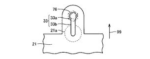
図9に、本実施の形態における電池パックの前部の第3の拡大概略平面図を示す。電池パックのアッパーケース21のビス穴33は、開口部33aおよび移動部33bを有する。ビス穴33は、車体の前後方向と平行な長手方向を有する。
FIG. 9 shows a third enlarged schematic plan view of the front portion of the battery pack in the present embodiment. The
開口部33aは、ボルト76の軸よりも径が大きくなるように形成されている。開口部33aは、ボルト76の頭部よりも径が小さくなるように形成されている。電池パックが車体に固定されるときには、開口部33aにボルト76の軸が配置される。
The opening 33 a is formed so that its diameter is larger than the axis of the
図10に、本実施の形態における電池パックの前部の第4の拡大概略平面図を示す。移動部33bは、ボルト76の軸の径よりも幅が小さくなるように形成されている。移動部33bは、車体の前後方向に延びるように形成されている。
FIG. 10 shows a fourth enlarged schematic plan view of the front portion of the battery pack in the present embodiment. The moving portion 33b is formed to have a width smaller than the diameter of the shaft of the
ビス穴33は、閉じた形状を有する。ビス穴33は、いずれの部分も電池パックの外側に連通しないように形成されている。ロアケースのビス穴35は、ビス穴33とほぼ同じ形状に形成されている(図3参照)。
The
図1から図3、図9および図10を参照して、本実施の形態におけるアッパーケース21は、薄肉部21aを有する。薄肉部21aは、薄肉部21aの周りの部分よりも厚さが薄くなるように形成されている。本実施の形態においては、薄肉部21aは、ビス穴33の移動部33bの端部を取り囲むように形成されている。
Referring to FIGS. 1 to 3, 9 and 10,
本実施の形態における薄肉部21aは、ボルト76の軸が移動部33bの端部に配置されたときに、ボルト76の頭部よりも径が大きくなるように形成されている。すなわち、薄肉部21aは、平面視したときに、ボルト76の頭部よりも大きくなるように形成されている。薄肉部21aは、電池パックに加わる衝撃により、ボルトの頭部により破壊されるように形成されている。
The thin-
図3を参照して、アッパーケース21と同様に、ロアケース22は、ビス穴35の周りに薄肉部22aを有する。薄肉部22aは、アッパーケース21の薄肉部21aの形状に対応するように形成されている。薄肉部22aは、アッパーケース21の薄肉部21aとほぼ同じ形状を有する。
Referring to FIG. 3, similarly to the
図4を参照して、本実施の形態においては、矢印85に示すように電池パック1に対して外部の高い位置からの衝撃が加わった場合を想定する。たとえば、本実施の形態における自動車に、大型の貨物自動車が後側から追突した場合を想定する。大型貨物自動車がフロア部材52の上面よりも高い位置に配置されたバンパを有する場合がある。このような場合には、電池パック1に対して直接的に衝撃が加わる。
Referring to FIG. 4, in the present embodiment, it is assumed that an impact from a high external position is applied to
図1から図3を参照して、このような外部の高い位置からの衝撃が加わった場合には、矢印99に示す車体の前側に向かって電池パック1が移動する。これに対して、サイドメンバ50に固定されたマウント55,56は移動しない。すなわち、ボルト74は移動しない。また、マウント55,56に固定されたボルト71,75,76は移動しない。
With reference to FIGS. 1 to 3, when such an impact from an external high position is applied,
図1、図2および図6を参照して、電池パック1の後側の端部においては、脚部27が矢印99に示す車体の前側に向かって移動する。このとき、脚部27のビス穴31は、移動部31bがボルト71の軸によって押し広げられる。ボルト71は、ビス穴31から抜ける。すなわち、ボルト71による固定が解除される。
With reference to FIGS. 1, 2, and 6, at the rear end portion of
図1、図2および図7を参照して、電池パック1の前側のビス穴32においては、電池パック1が矢印99に示す向きに移動する。ビス穴32の連通部32bは、ボルト75の軸により押し広げられる。図8に示すように、ボルト75は開口部32cに移動する。開口部32cは、ボルト75の頭部よりも大きくなるように形成されているため、ボルト75が開口部32cを通り抜ける状態になる。
With reference to FIGS. 1, 2, and 7, the
図1、図2および図9を参照して、電池パック1の前側のビス穴33においては、電池パック1が矢印99に示す向きに移動する。ビス穴33の移動部33bは、ボルト76の軸により押し広げられる。図10に示すように、ボルト76は、移動部33bのほぼ端部まで移動する。ボルト76は、薄肉部21aが形成されている領域の内部に移動する。
Referring to FIGS. 1, 2, and 9,
図11に、電池パックに対して外部の高い位置からの衝撃が加わったときの概略断面図を示す。図11は、図4に対応する概略断面図である。電池パック1は、矢印89に示すようにほぼ水平方向に移動した後に、矢印90に示す向きにほぼ鉛直方向に移動する。
FIG. 11 is a schematic cross-sectional view when an impact from a high external position is applied to the battery pack. FIG. 11 is a schematic cross-sectional view corresponding to FIG.
このときに、図1、図2および図6から図10を参照して、ボルト71は、脚部27から離れる。ボルト75は、ビス穴32の開口部32cから抜ける。ボルト76は、アッパーケース21に形成された薄肉部21aおよびロアケース22に形成された薄肉部22aを破壊しながらケース20から抜ける。
At this time, referring to FIGS. 1, 2, and 6 to 10, the
図11を参照して、アッパーケース21およびロアケース22は、ボルト73により互いに固定された状態を維持する。電池パック1は、マウント55,56から離脱することにより、衝撃のエネルギが吸収され、電池パック1の損傷を抑制することができる。また、本実施の形態においては、電池パック1がトランクルーム1に配置されているため、居住室内に電池パック1が侵入することを回避できる。
Referring to FIG. 11,
本実施の形態における導線26は、電池パック1がマウント55,56から離脱しても撓むように十分な長さを有する。この構成により、外部の高い位置からの衝撃が加わったときに、導線26が断線されてしまうことを抑制できる。
本実施の形態における電池パックの車載構造においては、電池パックに対して外部の高い位置からの衝撃が加わったときに、電池パックが支持部材から離脱するように形成されている。このため、電池パックが支持部材に固定されたままの状態で、電池パックが破壊されてしまうことを抑制できる。電池パックが支持部材に固定された状態で、電池パックが擦り切れ状に破壊されたり押し潰されたりすることを抑制できる。また、電池パックが支持部材から離脱することにより、電池パックに対する衝撃エネルギの一部を吸収して、電池パックの破損を抑制することができる。 In the on-vehicle structure of the battery pack in the present embodiment, the battery pack is formed so as to be detached from the support member when an impact from an external high position is applied to the battery pack. For this reason, it can suppress that a battery pack will be destroyed in the state in which the battery pack was being fixed to the support member. In the state where the battery pack is fixed to the supporting member, it can be suppressed or crushed or destroyed in shape fray battery packs. Further, when the battery pack is detached from the support member, it is possible to absorb a part of the impact energy with respect to the battery pack and suppress the damage of the battery pack.
一方で、電池パックに加わる外部の高い位置からの衝撃が小さなときには、電池パックは移動しないように支持部材に固定されている。たとえば、小型の自動車が追突してサイドメンバが変形する程度の衝撃の場合には、電池パックが離脱しないように固定されている。または、たとえば自動車が建造物に衝突して、トランクルームに載置されている重量物が電池パックに衝突した場合などの衝撃に対しては、電池パックが離脱しないように固定されている。 On the other hand, when the impact from an external high position applied to the battery pack is small, the battery pack is fixed to the support member so as not to move. For example, the battery pack is fixed so as not to be detached in the case of an impact that causes a side collision of a small automobile and deformation of a side member. Alternatively, for example, when the automobile collides with a building and a heavy object placed in the trunk room collides with the battery pack, the battery pack is fixed so as not to be detached.
ボルト75,76,71は、電池パックに対する所定の外部の高い位置からの衝撃の大きさに対して締付けトルクを決定する。また、脚部27に形成されたビス穴31の移動部31bの幅、ケースの前部に形成されたビス穴32の連通部32bの幅、およびケースの前部に形成されたビス穴33の移動部33bの幅は、電池パック1を移動させるべき外部の高い位置からの衝撃の大きさに対応して設定する。移動部31b,33bおよび連通部32bは、それぞれの幅がボルトの軸の径よりも大きくなるように形成されていても構わない。
図1から図3、および図7から図10を参照して、本実施の形態における電池パック1は、一の第1ビス挿通穴として、ケース20にビス穴32,34が形成されている。ビス穴32,34は、前側に形成された第1開口部と、後側に形成された第2開口部と、第1開口部および第2開口部を連通するように形成された連通部とを有する。また、本実施の形態における電池パックは、他の第1ビス挿通穴としてビス穴33,35が形成され、ビス穴33,35の周りに薄肉部21a,22aが形成されている。これらうちいずれかの構成により、外部の高い位置からの衝撃が加わったときに電池パックがサイドメンバから離脱する固定機構を提供することができる。
With reference to FIGS. 1 to 3 and FIGS. 7 to 10,
本実施の形態においては、第1開口部および第2開口部を有する第1ビス挿通穴、または、開口部、移動部および移動部の先端の周りに薄肉部を有する第1ビス挿通穴が形成されているが、この形態に限られず、いずれか一方の構成が採用されていても構わない。 In the present embodiment, a first screw insertion hole having a first opening and a second opening, or a first screw insertion hole having a thin portion around the opening, the moving portion, and the tip of the moving portion is formed. However, the present invention is not limited to this configuration, and either one of the configurations may be adopted.
さらに、第1ビス挿通穴は、これらの形態に限られず、電池パックが移動した後に、第1ビスによる固定が解除されるように形成されていればよい。たとえば、第1ビス挿通穴が平面形状が円形の開口部を含み、開口部の周りに薄肉部が形成されていても構わない。 Furthermore, the first screw insertion hole is not limited to these forms, and may be formed so that the fixation by the first screw is released after the battery pack moves. For example, the first screw insertion hole may include an opening having a circular planar shape, and a thin portion may be formed around the opening.
図12に、本実施の形態における他の電池パックの前部の概略平面図を示す。この電池パックは、第1ビス挿通穴の周りに薄肉部が形成されている。電池パックは、アッパーケース23を含む。アッパーケース23は、第1ビス挿通穴としてのビス穴30を含む。ビス穴30は、平面形状が円形に形成されている。アッパーケース23は、薄肉部23aを含む。薄肉部23aは、第1ビスとしてのボルト76が移行するための車両の前後方向に延びる移行領域およびボルト76が電池ケースから抜けるための破壊領域を有する。本実施の形態における破壊領域は、平面形状が円形に形成されている。移行領域の幅は、ボルト76の軸の径よりも小さくなるように形成されている。破壊領域は、ボルト76の頭部よりも大きくなるように形成されている。
FIG. 12 shows a schematic plan view of the front part of another battery pack according to the present embodiment. In this battery pack, a thin portion is formed around the first screw insertion hole. The battery pack includes an
本実施の形態における他の電池パックにおいては、電池パックに外部の高い位置からの衝撃が加わったときに、電池パックが車両前側に移動すると共に薄肉部23aの移行領域がボルト76により裂かれる。この後に、薄肉部23aの破壊領域がボルト76により破壊されることにより、ボルト76による電池パックの固定が解除される。
In another battery pack in the present embodiment, when an impact from an external high position is applied to the battery pack, the battery pack moves to the front side of the vehicle and the transition region of the
また、本実施の形態においては、蓄電パックの後側の脚部に、一部が外側に連通する、いわゆる開いた形状のビス穴が形成されているが、この形態に限られず、電池パックに外部の高い位置からの衝撃が加わったときに、固定が解除される任意の構成を採用することができる。たとえば、蓄電パックの脚部は、所定の衝撃以上の力が加わったときに、脚部自体が折れるように形成されていても構わない。 Further, in the present embodiment, a so-called open screw hole that is partly communicated with the outside is formed in the rear leg portion of the electricity storage pack. It is possible to adopt any configuration in which the fixation is released when an impact from an external high position is applied. For example, the leg part of the electricity storage pack may be formed so that the leg part itself is broken when a force greater than a predetermined impact is applied.
さらに、本実施の形態における第1ビス挿通穴は、電池パックの前側に形成されているが、この形態に限られず、任意の方向に形成することができる。たとえば、蓄電パックの側方に第1ビス挿通穴が形成されていても構わない。第1ビス挿通穴などのビス穴の延びる方向は、想定される衝撃が加わる方向とほぼ平行に形成されることが好ましい。 Furthermore, although the 1st screw insertion hole in this Embodiment is formed in the front side of a battery pack, it is not restricted to this form, It can form in arbitrary directions. For example, a first screw insertion hole may be formed on the side of the electricity storage pack. The direction in which the screw hole such as the first screw insertion hole extends is preferably formed substantially parallel to the direction in which the assumed impact is applied.
(実施の形態2)
図13および図14を参照して、本発明に基づく実施の形態2における蓄電パックの車載構造について説明する。本実施の形態における蓄電パックの車載構造は、蓄電パックの前側の端部において、ビスにより固定される部分の構造が実施の形態1と異なる。
(Embodiment 2)
With reference to FIG. 13 and FIG. 14, an in-vehicle structure of the electricity storage pack in the second embodiment based on the present invention will be described. The in-vehicle structure of the electricity storage pack in the present embodiment differs from that in
図13に、本実施の形態における電池パックの前部の概略斜視図を示す。矢印99は、車体の前側を示す。本実施の形態における電池パックは、ケース45を含む。ケース45は、アッパーケース46およびロアケース47を有する。ケース45は、前側の端部において、凹部45aを有する。凹部45aは、それぞれのボルトが配置される部分に形成されている。
FIG. 13 shows a schematic perspective view of the front portion of the battery pack in the present embodiment. An
凹部45aの底部には、段差部45bが形成されている。段差部45bは、断面形状が階段状になるように形成されている。段差部45bは、後側が高くなるように形成されている。凹部45aの底面には、第1ビス挿通穴としてのビス穴48が形成されている。ビス穴48は、車体の前後方向に長手方向を有するように形成されている。ビス穴48は、想定される衝撃力の方向に延びるように形成されている。
A
図14(a)に、本実施の形態における電池パックの前部の第1の拡大概略平面図を示す。ビス穴48は、前側に形成された第1開口部としての開口部48aと後側に形成された第2開口部としての開口部48cとを含む。ビス穴48は、開口部48aと開口部48cとが連通するように形成された連通部48bを有する。
FIG. 14A shows a first enlarged schematic plan view of the front portion of the battery pack in the present embodiment. The
開口部48cは、段差部45bに形成されている。開口部48cは、段差部45bを跨ぐように形成されている。開口部48cは、少なくとも一部が、開口部48aよりも高い部分に形成されている。開口部48aは、ボルト72の軸が挿通するように形成されている。開口部48aは、ボルト72の頭部が挿通しないように形成されている。
The
図14(b)に、本実施の形態における電池パックの前部の第2の拡大概略平面図を示す。開口部48cは、ボルト72の頭部が挿通するように形成されている。さらに、本実施の形態においては、座金79が固定に用いられている。開口部48cの幅は、座金79の径よりも大きくなるように形成されている。すなわち、開口部48cは、座金79が挿通するように形成されている。
FIG. 14B shows a second enlarged schematic plan view of the front portion of the battery pack in the present embodiment. The
図14(a)を参照して、本実施の形態における電池パックの車載構造においては、後側から外部の高い位置からの衝撃が電池パックに加わったときに、矢印99に示す向きに電池パックが移動する。電池パックは、ほぼ水平方向に移動する。
Referring to FIG. 14 (a), in the on-vehicle structure of the battery pack according to the present embodiment, the battery pack is oriented in the direction indicated by
図14(b)を参照して、平面視したときに、開口部48cの内側にボルト72および座金79が配置される。ボルト72および座金79は、開口部48cを通り抜ける。ボルト72および座金79の一部は、ケース45の裏側に配置され、ケース45から離れた状態になる。このように、本実施の形態においては、電池パックが移動したときにボルトの固定をより確実に解除することができる。
Referring to FIG. 14B, the
本実施の形態における段差部は、階段状になるように形成されているが、この形態に限られず、第2開口部の少なくとも一部が第1開口部よりも高い位置に配置されていれば構わない。たとえば、段差部は、角を有さないように断面形状が山形に形成され、山形の頂部にビスの頭部が挿通する開口部が形成されていても構わない。 The step portion in the present embodiment is formed to have a stepped shape, but is not limited to this form, and at least a part of the second opening is disposed at a position higher than the first opening. I do not care. For example, the stepped portion may be formed in a mountain shape so as not to have a corner, and an opening through which the screw head is inserted may be formed at the top of the mountain shape.
その他の構成、作用および効果については、実施の形態1と同様であるのでここでは説明を繰返さない。 Since other configurations, operations, and effects are the same as those in the first embodiment, description thereof will not be repeated here.
(実施の形態3)
図15から図17を参照して、本発明に基づく実施の形態3における蓄電パックの車載構造について説明する。本実施の形態における蓄電パックの車載構造は、電池パックの前部の構造が実施の形態1と異なる。
(Embodiment 3)
With reference to FIGS. 15 to 17, an in-vehicle structure of the electricity storage pack according to Embodiment 3 based on the present invention will be described. The on-vehicle structure of the electricity storage pack in the present embodiment is different from that of the first embodiment in the structure of the front part of the battery pack.
図15に、本実施の形態における電池パックの部分の概略断面図を示す。電池パック1の前側の端部において、幅方向の両側にはビス穴32が形成されている。ビス穴32にボルト75が配置されることにより、電池パック1の前側の端部がマウント55に固定されることは実施の形態1と同様である。
FIG. 15 is a schematic cross-sectional view of the battery pack portion in the present embodiment. Screw holes 32 are formed on both sides in the width direction at the front end of the
本実施の形態における電池パック1は、前側の端部において、第3ビスとしてのボルト77を有する。ボルト77は、アッパーケース21およびロアケース22を互いに固定するように形成されている。ボルト77は、電池パック1とマウント55とを固定しないように形成されている。
図16に、本実施の形態における電池パックの概略斜視図を示す。また、図16は、電池パックに衝撃が加わってサイドメンバから離脱したときの状態を示す。本実施の形態におけるケース20は、ボルト77を配置する部分が上側に突出するように形成されている。
FIG. 16 shows a schematic perspective view of the battery pack in the present embodiment. FIG. 16 shows a state when the battery pack is subjected to an impact and detached from the side member.
アッパーケース21は、前側の端部に上側に突出するように形成された突出部21bを有する。ロアケース22は、前側の端部に上側に突出するように形成された突出部22bを有する。突出部21bと突出部22bとは、互いに対応する位置に配置されている。突出部22bは、ボルト77を固定するためのナットを内側に配置できるように形成されている。
The
図17に、本実施の形態における電池パックの概略分解斜視図を示す。アッパーケース21の突出部21bには、平面形状が円形のビス穴38が形成されている。ロアケース22の突出部22bには、平面形状が円形のビス穴39が形成されている。ビス穴38およびビス穴39にボルト77が配置されることにより、アッパーケース21とロアケース22とが互いに固定される。
FIG. 17 shows a schematic exploded perspective view of the battery pack according to the present embodiment. A
電池パック1の後側の端部において、ボルト73によりアッパーケース21とロアケース22とが互いに固定されていることは、実施の形態1と同様である。
Similar to the first embodiment, the
本実施の形態における電池パック1は、サイドメンバに対する固定が解除されたときにおいても、前側の端部および後側の端部が、それぞれボルト73,77に固定されている。このため、アッパーケース21およびロアケース22が互いに固定された状態を維持することができ、電池パックの損傷をより確実に抑制することができる。
In the
本実施の形態においては、電池パックがサイドメンバから離脱したときに、アッパーケースとロアケースとが固定された状態に維持する固定手段として、ケースの前部に凹凸部が形成され、この凹凸部にケースを固定するためのボルトとナットが配置されている。固定手段としてはこの形態に限られず、支持部材から蓄電パックが離脱してもケースが固定されるように形成されていれば構わない。たとえば、アッパーケースとロアケースとが蓄電ケースの両側の側部で固定されていても構わない。 In the present embodiment, when the battery pack is detached from the side member, an uneven portion is formed on the front portion of the case as a fixing means for maintaining the upper case and the lower case in a fixed state. Bolts and nuts for fixing the case are arranged. The fixing means is not limited to this form, and any means may be used as long as the case is fixed even if the electricity storage pack is detached from the support member. For example, the upper case and the lower case may be fixed on the sides on both sides of the power storage case.
その他の構成、作用および効果については、実施の形態1と同様であるのでここでは説明を繰返さない。 Since other configurations, operations, and effects are the same as those in the first embodiment, description thereof will not be repeated here.
(実施の形態4)
図18から図22を参照して、本発明に基づく実施の形態4における蓄電パックの車載構造について説明する。本実施の形態における車載構造は、外部の高い位置からの衝撃が蓄電パックに加わったときに、蓄電パックを離脱させるための衝撃緩和手段が支持部材に形成されている。
(Embodiment 4)
With reference to FIGS. 18 to 22, an in-vehicle structure of the electricity storage pack according to the fourth embodiment based on the present invention will be described. In the in-vehicle structure in the present embodiment, when the impact from an external high position is applied to the electricity storage pack, the impact mitigating means for detaching the electricity storage pack is formed on the support member.
図18に、本実施の形態における電池パックの部分の概略断面図を示す。矢印99は、車体の前側を示す。本実施の形態における蓄電パックとしての電池パック2は、ケース40を含む。ケース40は、アッパーケース41およびロアケース42を有する。ロアケース42は、脚部28を有する。脚部28は、実施の形態1における脚部と同様の構成を有する。
FIG. 18 is a schematic cross-sectional view of the battery pack portion in the present embodiment. An
本実施の形態における支持部材は、マウント57を備える。マウント57は、電池パック2の前部に配置されている。電池パック2は、前側の端部が第2ビスとしてのボルト78により、マウント57に固定されている。また、ボルト78によりアッパーケース41とロアケース42とがマウント57に固定されている。電池パック2は、後側の端部において、ボルト73によりアッパーケース41とロアケース42とが互いに固定されている。
The support member in the present embodiment includes a
図19に、本実施の形態における電池パックの概略分解斜視図を示す。アッパーケース41の前側の端部には、ビス穴41aが形成されている。ビス穴41aは、平面形状が円形になるように形成されている。ロアケース42は、前側の端部にビス穴42aを有する。ビス穴42aは、平面形状が円形になるように形成されている。ビス穴42aは、アッパーケース41のビス穴41aに対応する位置に配置されている。
FIG. 19 is a schematic exploded perspective view of the battery pack according to the present embodiment. A
アッパーケース41は、後側の端部にビス穴41bを有する。ロアケース42は、後側の端部にビス穴42bを有する。ビス穴42bは、ビス穴41bに対応する位置に配置されている。
The
図18および図19を参照して、ケース40の前側の端部において、ビス穴41a,42aには、ボルト78が配置されている。ケース40の後側の端部において、ビス穴41b,42bには、ボルト73が配置されている。ボルト73は、ロアケース42の下面に配置されたナットと係合することにより固定されている。
Referring to FIGS. 18 and 19,
図20に、本実施の形態におけるマウントの概略斜視図を示す。マウント57は、前側の端部に第2ビス挿通穴としてのビス穴58を有する。ビス穴58は、前後方向に延びるように形成されている。ビス穴58は、ケース40のビス穴41a,42aに対応する位置に配置されている。
FIG. 20 is a schematic perspective view of the mount in the present embodiment. The
ビス穴58は、開口部58aと移動部58bとを有する。開口部58aの径は、ボルト78の軸の径よりも大きくなるように形成されている。開口部58aの径は、ボルト78の頭部の径よりも小さくなるように形成されている。移動部58bの幅は、ボルト78の軸の径よりも大きくなるように形成されている。移動部58bは、端部が外部に開口している。
The
本実施の形態における支持部材は、マウント57に固定されたリテーナ43を含む。リテーナ43は、マウント57の電池パックと接する部分の裏側に配置されている。本実施の形態におけるリテーナ43は、板状に形成されている。
The support member in the present embodiment includes a
図21に、本実施の形態におけるマウントを裏側から見たときのリテーナの部分の拡大概略下面図を示す。本実施の形態におけるリテーナ43は、破壊補助部を有する。破壊補助部は、リテーナ43のボルトの軸を挿通するための挿通穴の両側に配置されている。本実施の形態における破壊補助部は、切欠き部43aを有する。破壊補助部は、孔部43bを有する。切欠き部43aおよび孔部43bは、それぞれが車体の前後方向に並ぶように配置されている。
FIG. 21 shows an enlarged schematic bottom view of the retainer portion when the mount according to the present embodiment is viewed from the back side. The
本実施の形態におけるリテーナ43は、金属で形成されている。破壊補助部としての切欠き部43aおよび孔部43bは、電池パックが支持部材から離脱されるべき外部の高い位置からの衝撃の大きさに対応するように形成されている。
The
リテーナ43は、中央部43dと周辺部43cとを有する。中央部43dおよび周辺部43cは、切欠き部43aおよび孔部43bに仕切られている。中央部43dには、ボルト78を固定するためのナット44が固定されている。ナット44は、中央部分にボルトを挿通するための挿通穴44aを有する。中央部43dは、ナット44の挿通穴44aに対応するように、ボルト78の軸を通すための挿通穴を有する。
The
リテーナ43は、周辺部43cがマウント57に固定されている。本実施の形態においては、溶接によってリテーナ43がマウント57に固定されている。また、ナット44は、溶接によってリテーナ43に固定されている。
The
図18を参照して、矢印85に示すように電池パック2に外部の高い位置からの衝撃が加わった場合においては、電池パック2が車体の前側に向かって移動する。ケース40の脚部28は、マウント56との固定が解除される。
Referring to FIG. 18, when an impact from a high external position is applied to
図22に、電池パックに外部の高い位置からの衝撃が加わったときの前側のマウントの拡大概略下面図を示す。電池パック2は、矢印99に示す車体の前方向に移動する。リテーナは、破壊補助部の部分で破壊される。リテーナは、切欠き部43aおよび孔部43bが形成された部分が破壊される。リテーナ43においては、中央部43dと周辺部43cとの接続が破壊される。中央部43dは、周辺部43cから離れる。
FIG. 22 shows an enlarged schematic bottom view of the front mount when an impact from an external high position is applied to the battery pack.
リテーナの一部が破壊されることにより、電池パック2とマウント57との固定が解除される。リテーナの周辺部43cは、マウント57に固定されたままの状態である。リテーナの中央部43dは、電池パック2とともに離脱する。
When the retainer is partially destroyed, the
本実施の形態においては、たとえば、トランクルームに電池パックが配置された自動車に大型貨物自動車が追突して、電池パックに外部の高い位置からの衝撃が生じた場合には、リテーナが破壊される。一方で、電池パックに加わる衝撃が小さなときには、リテーナは破壊されずに、電池パックは支持部材に固定されている。たとえば、小型の自動車が追突して支持部材が変形する程度の衝撃の場合には、電池パックが離脱しないように形成されている。または、たとえば自動車が建造物に衝突して、トランクルームに載置されている重量物が電池パックに衝突した場合などの衝撃に対しては、電池パックが離脱しないように固定されている。 In the present embodiment, for example, when a large lorry collides with an automobile in which a battery pack is arranged in a trunk room and an impact from a high external position is generated on the battery pack, the retainer is destroyed. On the other hand, when the impact applied to the battery pack is small, the retainer is not broken and the battery pack is fixed to the support member. For example, the battery pack is formed so as not to be detached in the case of an impact to the extent that a small automobile collides and the support member is deformed. Alternatively, for example, when the automobile collides with a building and a heavy object placed in the trunk room collides with the battery pack, the battery pack is fixed so as not to be detached.
このように、支持部材がリテーナを有し、外部の高い位置からの衝撃が加わったときにリテーナが破壊されるように形成されていることにより、衝撃が加わったときに、蓄電パックが支持部材から離脱して蓄電パックの破損を抑制することができる。 As described above, the support member has a retainer, and the retainer is destroyed when an impact from an external high position is applied, so that when the impact is applied, the power storage pack is supported by the support member. The battery pack can be prevented from being damaged by being detached from the battery pack.
本実施の形態におけるリテーナは、破壊補助部として、切欠き部43aおよび孔部43bを有する。破壊補助部として、切欠き部および孔部のうち、少なくとも一方が形成されていることにより、リテーナが破壊される部分を容易に特定することができ、リテーナをスムーズに破壊させることができる。または、リテーナを破壊させるべき衝撃力を容易に調整することができる。
The retainer in the present embodiment has a
破壊補助部としては、切欠き部または開口部に限られず、リテーナの破壊位置が特定されるように形成されていれば構わない。たとえば、切欠き部や開口部の代わりに厚さが薄くなる部分が形成されていても構わない。 The destruction assisting part is not limited to the notch part or the opening part, and may be formed so that the destruction position of the retainer is specified. For example, a portion where the thickness is reduced may be formed instead of the notch or the opening.
また、本実施の形態における第2ビス挿通穴は、マウントの端部を切り欠いた形状を有するが、この形態に限られず、第2ビス挿通穴は、リテーナが破壊された後にリテーナの一部と蓄電パックとが一体的にマウントから離脱するように形成されていれば構わない。たとえば、第2ビス挿通穴は、マウントの幅方向のほぼ中央部分に形成され、閉じた形状を有する穴であっても構わない。 Further, the second screw insertion hole in the present embodiment has a shape in which the end portion of the mount is cut out, but is not limited to this form, and the second screw insertion hole is a part of the retainer after the retainer is broken. And the electricity storage pack may be formed so as to be integrally detached from the mount. For example, the second screw insertion hole may be a hole formed in a substantially central portion in the width direction of the mount and having a closed shape.
その他の構成、作用および効果については、実施の形態1と同様であるのでここでは説明を繰返さない。 Since other configurations, operations, and effects are the same as those in the first embodiment, description thereof will not be repeated here.
上述のそれぞれの図において、同一または相当する部分には、同一の符号を付している。 In the respective drawings described above, the same or corresponding parts are denoted by the same reference numerals.
なお、今回開示した上記実施の形態はすべての点で例示であって制限的なものではない。本発明の範囲は上記した説明ではなくて特許請求の範囲によって示され、特許請求の範囲と均等の意味および範囲内でのすべての変更を含むものである。 In addition, the said embodiment disclosed this time is an illustration in all the points, Comprising: It is not restrictive. The scope of the present invention is defined by the terms of the claims, rather than the description above, and includes all modifications within the scope and meaning equivalent to the terms of the claims.
1,2 電池パック、20 ケース、21,23 アッパーケース、21a 薄肉部、21b 突出部、22 ロアケース、22a,23a 薄肉部、22b 突出部、25 蓄電池、25a 電池セル、26 導線、27,28 脚部、30〜39 ビス穴、31a,32a,33a 開口部、31b,33b 移動部、32b 連通部、32c 開口部、40 ケース、41 アッパーケース、41a,41b ビス穴、42 ロアケース、42a,42b ビス穴、43 リテーナ、43a 切欠き部、43b 孔部、43c 周辺部、43d 中央部、44 ナット、44a 挿通穴、45 ケース、45a 凹部、45b 段差部、46 アッパーケース、47 ロアケース、48 ビス穴、48a 開口部、48b 連通部、48c 開口部、50 サイドメンバ、50a キックアップ部、51 クロスメンバ、52 フロア部材、55〜57 マウント、55a ビス穴、56a ビス穴、58 ビス穴、58a 開口部、58b 移動部、60 後輪、61 ボディ、61a 後面、62 後部座席、63 パーティションパネル、64 トランクルーム、71〜78 ボルト、79 座金、85,89,90,99 矢印。
1, 2 Battery pack, 20 case, 21, 23 Upper case, 21a Thin part, 21b Protruding part, 22 Lower case, 22a, 23a Thin part, 22b Protruding part, 25 Storage battery, 25a Battery cell, 26 Conductor, 27, 28 Legs Part, 30-39 screw hole, 31a, 32a, 33a opening part, 31b, 33b moving part, 32b communication part, 32c opening part, 40 case, 41 upper case, 41a, 41b screw hole, 42 lower case, 42a, 42b screw Hole, 43 Retainer, 43a Notch, 43b Hole, 43c Peripheral, 43d Center, 44 Nut, 44a Insertion hole, 45 Case, 45a Recess, 45b Step, 46 Upper case, 47 Lower case, 48 Screw hole, 48a opening, 48b communicating portion, 48c opening, 50
Claims (2)
前記蓄電パックは、前記支持部材の上側に第1ビスによって固定され、
前記蓄電パックは、後部座席よりも車両後側に配置され、
前記蓄電パックは、前記第1ビスを挿通するための第1ビス挿通穴を有し、
前記第1ビス挿通穴は、閉じた形状を有し、
前記第1ビス挿通穴は、第1開口部と、
前記第1開口部よりも車両後側に配置された第2開口部と、
前記第1開口部と前記第2開口部とを連通するように形成された連通部と
を含み、
前記第1開口部は、前記第1ビスの頭部よりも小さくなるように形成され、
前記第2開口部は、前記頭部よりも大きくなるように形成され、
前記蓄電パックは、階段状になるように形成された段差部を有し、
前記第1ビス挿通穴は、前記段差部に形成され、
前記第2開口部は、少なくとも一部が前記第1開口部よりも高い部分に形成され、
前記蓄電パックは、前記蓄電パックに車両後側から衝撃が加わったときに、前記第1ビスの位置が前記第1開口部から前記第2開口部に移行することにより、車両前側に移動するように形成され、
前記蓄電パックは、前記第1ビスが前記第2開口部から抜けることにより、前記第1ビスによる固定が解除されるように形成された、蓄電パックの車載構造。 A support member for supporting the electricity storage pack;
The electricity storage pack is fixed to the upper side of the support member by a first screw,
The electricity storage pack is disposed on the rear side of the vehicle from the rear seat,
The electricity storage pack has a first screw insertion hole for inserting the first screw,
The first screw insertion hole has a closed shape,
The first screw insertion hole has a first opening,
A second opening disposed on the rear side of the vehicle with respect to the first opening;
A communication portion formed so as to communicate the first opening and the second opening;
The first opening is formed to be smaller than the head of the first screw,
The second opening is formed to be larger than the head,
The electricity storage pack has a step portion formed to be stepped,
The first screw insertion hole is formed in the stepped portion,
The second opening is formed in a portion at least partially higher than the first opening,
The electric storage pack moves to the front side of the vehicle by moving the position of the first screw from the first opening to the second opening when an impact is applied to the electric storage pack from the rear side of the vehicle. Formed into
The electric storage pack is an in-vehicle structure of the electric storage pack formed such that the first screw is released from the second opening and the fixation by the first screw is released.
前記ケースは、前記蓄電機器を載置するためのロアケースと、
前記ロアケースに固定され、前記蓄電機器を覆うように形成されたアッパーケースと
を含み、
前記ロアケースおよび前記アッパーケースは、第3ビスによって互いに固定され、
前記第3ビスは、前記蓄電パックと前記支持部材とを固定しないように形成された、請求項1に記載の蓄電パックの車載構造。 The electricity storage pack includes a case for placing the electricity storage device inside,
The case includes a lower case for mounting the power storage device,
An upper case fixed to the lower case and formed to cover the power storage device,
The lower case and the upper case are fixed to each other by a third screw,
The on-vehicle structure of the electricity storage pack according to claim 1 , wherein the third screw is formed so as not to fix the electricity storage pack and the support member.
Priority Applications (5)
| Application Number | Priority Date | Filing Date | Title |
|---|---|---|---|
| JP2006053225A JP4935112B2 (en) | 2006-02-28 | 2006-02-28 | In-vehicle structure of power storage pack |
| PCT/JP2007/054120 WO2007100118A1 (en) | 2006-02-28 | 2007-02-26 | Structure for mounting electricity storage pack on vehicle |
| CN2007800071058A CN101395022B (en) | 2006-02-28 | 2007-02-26 | Structure for mounting electricity storage pack on vehicle |
| US12/223,933 US8037960B2 (en) | 2006-02-28 | 2007-02-26 | Structure for mounting electricity storage pack on vehicle |
| DE112007000474.6T DE112007000474B4 (en) | 2006-02-28 | 2007-02-26 | A structure for mounting an electricity storage unit on a vehicle |
Applications Claiming Priority (1)
| Application Number | Priority Date | Filing Date | Title |
|---|---|---|---|
| JP2006053225A JP4935112B2 (en) | 2006-02-28 | 2006-02-28 | In-vehicle structure of power storage pack |
Publications (2)
| Publication Number | Publication Date |
|---|---|
| JP2007230329A JP2007230329A (en) | 2007-09-13 |
| JP4935112B2 true JP4935112B2 (en) | 2012-05-23 |
Family
ID=38459210
Family Applications (1)
| Application Number | Title | Priority Date | Filing Date |
|---|---|---|---|
| JP2006053225A Expired - Lifetime JP4935112B2 (en) | 2006-02-28 | 2006-02-28 | In-vehicle structure of power storage pack |
Country Status (5)
| Country | Link |
|---|---|
| US (1) | US8037960B2 (en) |
| JP (1) | JP4935112B2 (en) |
| CN (1) | CN101395022B (en) |
| DE (1) | DE112007000474B4 (en) |
| WO (1) | WO2007100118A1 (en) |
Families Citing this family (141)
| Publication number | Priority date | Publication date | Assignee | Title |
|---|---|---|---|---|
| JP4649849B2 (en) * | 2004-03-02 | 2011-03-16 | トヨタ自動車株式会社 | Storage mechanism mounting structure |
| JP5141026B2 (en) * | 2006-02-27 | 2013-02-13 | トヨタ自動車株式会社 | In-vehicle structure of power storage pack |
| JP4225363B2 (en) * | 2007-07-24 | 2009-02-18 | トヨタ自動車株式会社 | Vehicle equipped with internal combustion engine and rotating electric machine as power source |
| JP2009090818A (en) * | 2007-10-09 | 2009-04-30 | Toyota Motor Corp | Fixed structure for on-vehicle equipment |
| JP2009150523A (en) * | 2007-12-21 | 2009-07-09 | Toyota Motor Corp | Equipment mounting structure |
| US20090186672A1 (en) * | 2008-01-17 | 2009-07-23 | Research In Motion Limited | Systems and methods for maintaining data integrity of storage media of an electronic device |
| GB0811321D0 (en) * | 2008-06-19 | 2008-07-30 | Tennant Scotland Ltd | Cleaning machine |
| US8167262B2 (en) * | 2009-01-10 | 2012-05-01 | Ford Global Technologies, Llc | Power converter mounting assemblies |
| EP2426775A4 (en) * | 2009-04-28 | 2013-10-30 | Hitachi Ltd | ELECTRICITY STORAGE MODULE AND ELECTRICITY STORAGE DEVICE WITH THE SAME |
| JP5077611B2 (en) | 2009-05-28 | 2012-11-21 | トヨタ自動車株式会社 | Fuel cell system and vehicle |
| US8932769B2 (en) | 2009-05-28 | 2015-01-13 | Toyota Jidosha Kabushiki Kaisha | Fuel cell assembly and vehicle |
| US8459399B2 (en) | 2009-05-28 | 2013-06-11 | Toyota Jidosha Kabushiki Kaisha | Fuel cell system and vehicle |
| JP5077610B2 (en) | 2009-05-28 | 2012-11-21 | トヨタ自動車株式会社 | Fuel cell system and vehicle |
| JP2010284984A (en) * | 2009-06-09 | 2010-12-24 | Fuji Heavy Ind Ltd | Vehicle battery mounting structure |
| DE102009031779A1 (en) * | 2009-07-06 | 2011-01-13 | GM Global Technology Operations, Inc., Detroit | Floor structure for a motor vehicle |
| JP5531478B2 (en) | 2009-07-16 | 2014-06-25 | 日産自動車株式会社 | battery pack |
| WO2011013634A1 (en) * | 2009-07-27 | 2011-02-03 | 本田技研工業株式会社 | Electric component mounting structure for vehicle |
| JP5099526B2 (en) * | 2009-10-08 | 2012-12-19 | トヨタ自動車東日本株式会社 | Battery mounting structure |
| JP5417162B2 (en) * | 2009-12-28 | 2014-02-12 | 株式会社日立製作所 | Power storage device |
| US8336657B2 (en) * | 2010-02-12 | 2012-12-25 | Ford Global Technologies, Llc | Support structure for inverter system controller module |
| FR2957888B1 (en) * | 2010-03-29 | 2012-03-23 | Renault Sa | VEHICLE AND SUPPORT FOR ENERGY TANK |
| JP5423559B2 (en) * | 2010-04-20 | 2014-02-19 | トヨタ自動車株式会社 | Material mounting structure on the body |
| JP5604971B2 (en) * | 2010-05-17 | 2014-10-15 | 日産自動車株式会社 | Vehicle collision safety device |
| WO2011145407A1 (en) * | 2010-05-18 | 2011-11-24 | スズキ株式会社 | Power source device protection structure |
| CN102822009B (en) * | 2010-05-26 | 2014-11-19 | 铃木株式会社 | Structure for vehicle body rear portion |
| JP5156057B2 (en) * | 2010-06-25 | 2013-03-06 | 富士重工業株式会社 | Mounting structure for vehicle battery box |
| JP5071538B2 (en) * | 2010-09-03 | 2012-11-14 | トヨタ自動車株式会社 | Battery mounting structure for vehicles |
| JP5228076B2 (en) | 2010-09-03 | 2013-07-03 | 日立ビークルエナジー株式会社 | In-vehicle power storage device |
| JP5434860B2 (en) * | 2010-09-17 | 2014-03-05 | トヨタ車体株式会社 | Battery pack mounting structure in vehicle |
| DE102010048102A1 (en) | 2010-10-09 | 2012-04-12 | Audi Ag | Vehicle with a crash energy absorbable traction battery |
| JP5528988B2 (en) * | 2010-11-16 | 2014-06-25 | 本田技研工業株式会社 | Support structure for vehicle battery unit |
| AT510815B1 (en) | 2010-11-17 | 2014-06-15 | Avl List Gmbh | MOUNTING DEVICE FOR AT LEAST ONE BATTERY MODULE |
| AT510801B1 (en) | 2010-11-17 | 2014-06-15 | Avl List Gmbh | MOUNTING DEVICE FOR AT LEAST ONE BATTERY MODULE |
| US20120161472A1 (en) | 2010-12-22 | 2012-06-28 | Tesla Motors, Inc. | System for Absorbing and Distributing Side Impact Energy Utilizing an Integrated Battery Pack |
| US8875828B2 (en) * | 2010-12-22 | 2014-11-04 | Tesla Motors, Inc. | Vehicle battery pack thermal barrier |
| US8702161B2 (en) | 2010-12-22 | 2014-04-22 | Tesla Motors, Inc. | System for absorbing and distributing side impact energy utilizing an integrated battery pack and side sill assembly |
| US8286743B2 (en) | 2010-12-22 | 2012-10-16 | Tesla Motors, Inc. | Vehicle battery pack ballistic shield |
| DE102010056261B4 (en) * | 2010-12-24 | 2025-06-26 | Audi Ag | Device for holding a battery in a vehicle body |
| DE102011002650B4 (en) * | 2011-01-13 | 2023-12-07 | Ford Global Technologies, Llc | motor vehicle |
| JP5270702B2 (en) * | 2011-02-14 | 2013-08-21 | トヨタ自動車株式会社 | Vehicle equipment mounting structure |
| CN103493244B (en) * | 2011-05-19 | 2016-04-27 | 株式会社Lg化学 | Battery pack with high structural stability |
| JP5609804B2 (en) * | 2011-07-25 | 2014-10-22 | トヨタ自動車株式会社 | Terminal protection structure and vehicle |
| JP5642650B2 (en) * | 2011-10-18 | 2014-12-17 | アイシン軽金属株式会社 | Battery-mounted structure for battery modules |
| JP5906689B2 (en) * | 2011-11-22 | 2016-04-20 | トヨタ自動車株式会社 | Vehicle battery mounting structure |
| JP5741406B2 (en) * | 2011-11-28 | 2015-07-01 | トヨタ自動車株式会社 | In-vehicle structure of power storage device |
| KR101400090B1 (en) * | 2011-12-14 | 2014-05-28 | 주식회사 엘지화학 | Battery Module Assembly Having Bus Bar Assembly on the Front and Battery Pack Employed with the Same |
| JP2013199196A (en) * | 2012-03-26 | 2013-10-03 | Suzuki Motor Corp | Battery pack mounting structure for electric car |
| US8602146B2 (en) | 2012-04-10 | 2013-12-10 | Toyota Motor Engineering & Manufacturing North America, Inc. | Vehicle construction method to prevent battery damage in rear impact using optimized bracket separation |
| US8585066B2 (en) | 2012-04-12 | 2013-11-19 | Toyota Motor Engineering & Manufacturing North America, Inc. | Electric vehicle construction methods for frontal impact |
| US8646792B2 (en) | 2012-04-12 | 2014-02-11 | Toyota Motor Engineering & Manufacturing North America, Inc. | Subframe intrusion control by steering gear catcher |
| US8540259B1 (en) | 2012-04-12 | 2013-09-24 | Toyota Motor Engineering & Manufacturing North America, Inc. | Construction method to control front engine compartment deformation |
| US8646790B2 (en) | 2012-04-12 | 2014-02-11 | Toyota Motor Engineering & Manufacturing North America, Inc. | Sub-frame intrusion control by ramping during frontal impact for electric vehicle battery protection |
| US8613461B2 (en) | 2012-04-12 | 2013-12-24 | Toyota Motor Engineering & Manufacturing North America, Inc. | Tether approach to control underbody energy absorption interaction with subframe |
| US8646791B2 (en) | 2012-04-12 | 2014-02-11 | Toyota Motor Engineering & Manufacturing North America, Inc. | Electric vehicle construction methods for frontal impact utilizing deformation shape control |
| JP5983063B2 (en) * | 2012-06-08 | 2016-08-31 | スズキ株式会社 | In-vehicle structure of battery pack |
| JP5991048B2 (en) * | 2012-07-02 | 2016-09-14 | コベルコ建機株式会社 | Power storage device and construction machine equipped with the same |
| JP6232693B2 (en) * | 2012-10-04 | 2017-11-22 | 日産自動車株式会社 | Fastening structure for electric parts for vehicles |
| JP5924225B2 (en) * | 2012-10-09 | 2016-05-25 | トヨタ自動車株式会社 | Battery equipment mounting structure for vehicles |
| WO2014063018A1 (en) | 2012-10-19 | 2014-04-24 | Agility Fuel Systems, Inc. | Systems and methods for mounting a fuel system |
| US9174520B2 (en) * | 2012-10-31 | 2015-11-03 | Honda Motor Co., Ltd. | Electric vehicle |
| JP6024895B2 (en) * | 2012-11-29 | 2016-11-16 | 三菱自動車工業株式会社 | Automotive battery pack |
| JP2014120346A (en) * | 2012-12-17 | 2014-06-30 | Denso Corp | Battery pack |
| JP6011320B2 (en) * | 2012-12-25 | 2016-10-19 | スズキ株式会社 | Vehicle rear structure |
| JP5928365B2 (en) * | 2013-02-13 | 2016-06-01 | トヨタ自動車株式会社 | Retaining structure for vehicle rear load |
| WO2014128855A1 (en) * | 2013-02-20 | 2014-08-28 | トヨタ自動車株式会社 | Electric vehicle |
| FR3003513B1 (en) * | 2013-03-19 | 2015-03-13 | Renault Sa | ENERGY ABSORPTION DEVICE FOR ATTACHING A TRACTION BATTERY OF AN ELECTRIC OR HYBRID VEHICLE |
| CN104057811B (en) * | 2013-03-20 | 2017-08-22 | 比亚迪股份有限公司 | The arrangement of automobile and its electrokinetic cell |
| JP6021737B2 (en) * | 2013-05-22 | 2016-11-09 | 住友重機械工業株式会社 | Power storage device and work machine |
| DE102013106433B4 (en) * | 2013-06-20 | 2024-05-08 | Dr. Ing. H.C. F. Porsche Aktiengesellschaft | Supporting frame for a motor vehicle |
| JP5854012B2 (en) * | 2013-09-13 | 2016-02-09 | トヨタ自動車株式会社 | Service hole cover and vehicle unit mounting structure |
| JP5880509B2 (en) * | 2013-09-25 | 2016-03-09 | トヨタ自動車株式会社 | Vehicle rear structure |
| US9630486B2 (en) * | 2013-12-02 | 2017-04-25 | Honda Motor Co., Ltd. | Vehicle |
| US9139074B2 (en) * | 2014-01-16 | 2015-09-22 | Ford Global Technologies, Llc | Methods and devices for positioning a traction battery on a hybrid or electric vehicle |
| US9061714B1 (en) * | 2014-01-24 | 2015-06-23 | Atieva, Inc. | EV battery pack protection system utilizing an undercarriage debris trap |
| JP6094548B2 (en) | 2014-08-29 | 2017-03-15 | 株式会社デンソー | Electronic device housing |
| FR3025572B1 (en) * | 2014-09-05 | 2017-02-24 | Renault Sa | VEHICLE WITH AN INCOMPRESSIBLE ELEMENT FIXED ON A COMPRESSIBLE ELEMENT IN CASE OF COLLISION |
| JP6350317B2 (en) * | 2015-02-03 | 2018-07-04 | トヨタ自動車株式会社 | Air intake duct mounting structure |
| DE102015003643B3 (en) * | 2015-03-19 | 2016-06-16 | Audi Ag | motor vehicle |
| DE202016103720U1 (en) * | 2015-07-30 | 2016-08-31 | Ford Global Technologies, Llc | Sliding protective battery support carrier |
| US9643660B2 (en) | 2015-08-27 | 2017-05-09 | Atieva, Inc. | Bumper assembly for an undercarriage mounted battery pack |
| US9517686B1 (en) * | 2015-09-03 | 2016-12-13 | Ford Global Technologies, Llc | Traction battery dual-stage mounting bracket |
| JP6118381B2 (en) * | 2015-09-30 | 2017-04-19 | 富士重工業株式会社 | Automotive battery |
| JP6442392B2 (en) * | 2015-10-22 | 2018-12-19 | 本田技研工業株式会社 | In-vehicle fuel cell system |
| JP6414095B2 (en) * | 2016-02-17 | 2018-10-31 | トヨタ自動車株式会社 | Fuel cell vehicle |
| JP6544311B2 (en) | 2016-07-14 | 2019-07-17 | トヨタ自動車株式会社 | In-vehicle equipment fixed structure |
| JP6836125B2 (en) * | 2016-09-15 | 2021-02-24 | 三菱自動車工業株式会社 | Spare tire dropout prevention device |
| JP2018056094A (en) * | 2016-09-30 | 2018-04-05 | 日立オートモティブシステムズ株式会社 | Battery pack |
| EP3326853B1 (en) * | 2016-11-23 | 2020-04-29 | MAGNA STEYR Fahrzeugtechnik AG & Co KG | Battery holder assembly |
| US10431785B2 (en) * | 2016-11-30 | 2019-10-01 | Ford Global Technologies, Llc | Battery pack array frames with integrated fastener housings |
| US10370035B2 (en) * | 2016-12-08 | 2019-08-06 | Inevit Llc | Motor guidance component configured to direct movement of a dislodged electric motor of an electric vehicle in response to crash forces |
| US9937781B1 (en) * | 2016-12-19 | 2018-04-10 | GM Global Technology Operations LLC | Battery pack mounting architecture with shear plate for electric drive motor vehicles |
| JP2018113153A (en) * | 2017-01-11 | 2018-07-19 | トヨタ自動車株式会社 | Battery pack |
| DE102017100685A1 (en) * | 2017-01-16 | 2018-07-19 | Dr. Ing. H.C. F. Porsche Aktiengesellschaft | Energy supply system for a motor vehicle |
| US9963028B1 (en) * | 2017-02-21 | 2018-05-08 | Ford Global Technologies, Llc | Battery support structure for electrified vehicle |
| DE102017103668A1 (en) * | 2017-02-22 | 2018-08-23 | Benteler Automobiltechnik Gmbh | Battery carrier with plastic lower shell and integrated induction line and method for its production |
| JP6589909B2 (en) * | 2017-03-01 | 2019-10-16 | トヨタ自動車株式会社 | vehicle |
| JP6705404B2 (en) * | 2017-03-16 | 2020-06-03 | トヨタ自動車株式会社 | Vehicle rear structure |
| JP6819439B2 (en) * | 2017-04-21 | 2021-01-27 | トヨタ自動車株式会社 | Fuel cell vehicle |
| JP6851260B2 (en) * | 2017-05-24 | 2021-03-31 | 株式会社クボタ | Electric work vehicle |
| US10549706B2 (en) * | 2017-06-22 | 2020-02-04 | Ford Global Technologies, Llc | Battery pack mounting assembly |
| JP6447694B2 (en) * | 2017-09-27 | 2019-01-09 | 株式会社豊田自動織機 | Battery module |
| JP6900882B2 (en) | 2017-11-20 | 2021-07-07 | トヨタ自動車株式会社 | Vehicle undercarriage |
| CN207818678U (en) * | 2017-12-28 | 2018-09-04 | 宁德时代新能源科技股份有限公司 | Shell, battery module and battery pack |
| JP7101489B2 (en) * | 2018-02-01 | 2022-07-15 | アイシン軽金属株式会社 | Vehicle mounting structure of battery module |
| JP6962230B2 (en) * | 2018-02-16 | 2021-11-05 | トヨタ自動車株式会社 | Battery pack |
| JP6988590B2 (en) * | 2018-03-09 | 2022-01-05 | トヨタ自動車株式会社 | Vehicle rear structure |
| JP7006390B2 (en) * | 2018-03-09 | 2022-01-24 | トヨタ自動車株式会社 | Vehicle lower body structure |
| JP7024589B2 (en) * | 2018-05-10 | 2022-02-24 | トヨタ自動車株式会社 | In-vehicle structure of electrical equipment |
| US10710527B2 (en) * | 2018-07-10 | 2020-07-14 | Kawasaki Jukogyo Kabushiki Kaisha | Utility vehicle |
| US10780923B2 (en) * | 2018-07-13 | 2020-09-22 | Ford Global Technologies, Llc | Vehicle platform |
| DE102018118500A1 (en) * | 2018-07-31 | 2020-02-06 | Dr. Ing. H.C. F. Porsche Aktiengesellschaft | Electric vehicle component |
| CN108909840A (en) * | 2018-08-10 | 2018-11-30 | 深圳市德塔防爆电动汽车有限公司 | Adapt to the electric car of thin layer operation |
| CA3110459C (en) | 2018-08-24 | 2024-06-18 | Hexagon Purus North America Holdings Inc. | Battery system for heavy duty vehicles |
| US11007899B2 (en) * | 2018-10-23 | 2021-05-18 | Chongqing Jinkang New Energy Vehicle Co., Ltd | Mounting structures for battery packs in electric vehicles |
| CN111129377B (en) * | 2018-11-01 | 2024-09-10 | 宁德时代新能源科技股份有限公司 | Battery box |
| JP7224193B2 (en) * | 2019-01-29 | 2023-02-17 | ダイハツ工業株式会社 | Battery structure fixing structure |
| CA3136944A1 (en) | 2019-04-19 | 2020-10-22 | Hexagon Purus North America Holdings Inc. | Electric powertrain system for heavy duty vehicles |
| WO2020215023A1 (en) * | 2019-04-19 | 2020-10-22 | Hexagon Purus North America Holdings Inc. | Electric front end accessory devices assembly |
| US12059949B2 (en) | 2019-06-19 | 2024-08-13 | Nissan Motor Co., Ltd. | Installation structure of electrical component module in vehicle |
| CN118769857A (en) * | 2019-06-27 | 2024-10-15 | 奥动新能源汽车科技有限公司 | Positioning seat, positioning mechanism, quick-change bracket assembly and electric vehicle |
| JP2021024428A (en) * | 2019-08-05 | 2021-02-22 | トヨタ自動車株式会社 | vehicle |
| CA3161967C (en) | 2019-11-26 | 2025-05-13 | Hexagon Purus North America Holdings Inc. | Electric vehicle power distribution and drive control modules |
| CN121406886A (en) | 2020-01-03 | 2026-01-27 | 特斯拉公司 | Selective extraction of lithium from clay minerals |
| JP2021109593A (en) * | 2020-01-14 | 2021-08-02 | トヨタ自動車株式会社 | Vehicle rear structure of electric vehicle |
| KR102693863B1 (en) * | 2020-01-23 | 2024-08-12 | 주식회사 엘지에너지솔루션 | Battery Pack With Improved Vibration Resistance |
| FR3109558B1 (en) | 2020-04-22 | 2024-03-08 | Renault Sas | Reinforcement for electric or hybrid vehicle equipped with a traction battery fixed on said reinforcement |
| US11926207B2 (en) | 2020-10-09 | 2024-03-12 | Hexagon Purus North America Holdings Inc. | Battery and auxiliary components for vehicle trailer |
| EP4259495A4 (en) | 2020-12-11 | 2024-11-06 | Hexagon Purus North America Holdings Inc. | Trailer hookup breakaway mitigation systems and methods |
| KR102704227B1 (en) * | 2021-01-08 | 2024-09-09 | 주식회사 엘지에너지솔루션 | Multi battery pack with compact structure |
| CN112909416B (en) * | 2021-02-03 | 2022-09-02 | 浙江工业职业技术学院 | New energy automobile battery fixing device convenient to dismouting |
| US11919404B2 (en) | 2021-07-19 | 2024-03-05 | Fca Us Llc | Vehicle high voltage battery case attachment system |
| JP7769512B2 (en) * | 2021-11-01 | 2025-11-13 | 株式会社Subaru | Battery module protection structure |
| DE102021129120A1 (en) | 2021-11-09 | 2023-05-11 | Bayerische Motoren Werke Aktiengesellschaft | Energy storage floor system for an electrically driven motor vehicle |
| JP7643313B2 (en) * | 2021-12-06 | 2025-03-11 | トヨタ自動車株式会社 | Vehicle rear structure |
| FR3137797B1 (en) * | 2022-07-07 | 2024-05-24 | Psa Automobiles Sa | TRACTION BATTERY COMPRISING A SEPARATION PLATE FIXED BY SCREWING WITH AN OBLONG HOLE SECURED IN CASE OF SIDE IMPACT, VEHICLE AND METHOD BASED ON SUCH A BATTERY |
| US12233702B2 (en) * | 2022-11-03 | 2025-02-25 | Ford Global Technologies, Llc | Structural assembly for battery structure of electric vehicle |
| DE102023108260A1 (en) | 2023-03-31 | 2024-10-02 | Bayerische Motoren Werke Aktiengesellschaft | Screw connection for a vehicle and vehicle |
| CN219692714U (en) * | 2023-03-31 | 2023-09-15 | 宁德时代新能源科技股份有限公司 | Energy storage equipment |
| KR20250025841A (en) * | 2023-08-16 | 2025-02-25 | 주식회사 엘지에너지솔루션 | Battery pack |
| EP4521515B1 (en) * | 2023-09-07 | 2026-03-18 | FPT Industrial S.p.A. | Fixing system for a vehicular battery system |
| WO2025203596A1 (en) * | 2024-03-29 | 2025-10-02 | 株式会社Subaru | Battery protection structure |
Family Cites Families (25)
| Publication number | Priority date | Publication date | Assignee | Title |
|---|---|---|---|---|
| DE3423954C1 (en) * | 1984-06-29 | 1986-01-02 | Daimler-Benz Ag, 7000 Stuttgart | Fuel tank arrangement in the rear area of a motor vehicle |
| JPS62122731A (en) * | 1985-06-19 | 1987-06-04 | Toshiba Mach Co Ltd | T-die for extrusion molding |
| JPH07107475B2 (en) * | 1987-11-09 | 1995-11-15 | 三洋電機株式会社 | Cold temperature controller |
| JP2651185B2 (en) * | 1988-03-22 | 1997-09-10 | マツダ株式会社 | Automotive steering support structure |
| JP2932127B2 (en) | 1992-10-02 | 1999-08-09 | トヨタ自動車株式会社 | Battery support structure for electric vehicles |
| JPH06270694A (en) * | 1993-03-22 | 1994-09-27 | Toyota Motor Corp | Battery carrier support structure for electric vehicles |
| JP2932134B2 (en) * | 1993-03-22 | 1999-08-09 | トヨタ自動車株式会社 | Energy absorption control structure for electric vehicles |
| JP3022085B2 (en) | 1993-09-16 | 2000-03-15 | 日産自動車株式会社 | Battery frame fixing part structure of electric vehicle |
| JPH0781432A (en) * | 1993-09-20 | 1995-03-28 | Nissan Motor Co Ltd | Battery fixing structure for electric vehicles |
| JP2982582B2 (en) * | 1993-10-21 | 1999-11-22 | トヨタ自動車株式会社 | Battery support structure for electric vehicles |
| JPH08133096A (en) * | 1994-11-11 | 1996-05-28 | Toyota Motor Corp | Mounting structure for electric vehicle battery and steering gear box |
| JP2000203460A (en) * | 1999-01-14 | 2000-07-25 | Hino Motors Ltd | Car body structure of truck |
| JP3379498B2 (en) * | 1999-12-17 | 2003-02-24 | 日産自動車株式会社 | Vehicle pedal bracket fixing structure |
| US6293059B1 (en) * | 2000-01-24 | 2001-09-25 | Robert F. Goodwin | Hurricane protective system for windows and doors |
| JP3900797B2 (en) * | 2000-07-05 | 2007-04-04 | 三菱自動車工業株式会社 | Power plant support structure |
| JP3851124B2 (en) | 2001-07-31 | 2006-11-29 | 三洋電機株式会社 | Automotive power supply and automobile equipped with this power supply |
| JP2003327155A (en) * | 2002-05-09 | 2003-11-19 | Toyota Motor Corp | Bolt fastening structure and structure support member |
| JP4063098B2 (en) * | 2003-02-13 | 2008-03-19 | 日産自動車株式会社 | Battery support device |
| JP4136700B2 (en) * | 2003-02-14 | 2008-08-20 | トヨタ自動車株式会社 | Worm shaft movable amount adjusting method and reduction gear for electric power steering device |
| JP4274819B2 (en) | 2003-03-04 | 2009-06-10 | 富士重工業株式会社 | Battery mounting structure |
| JP4649849B2 (en) * | 2004-03-02 | 2011-03-16 | トヨタ自動車株式会社 | Storage mechanism mounting structure |
| JP2006035915A (en) * | 2004-07-22 | 2006-02-09 | Sanyo Electric Co Ltd | Power supply for vehicle |
| JP2007015600A (en) * | 2005-07-08 | 2007-01-25 | Nissan Motor Co Ltd | Battery assembly structure |
| JP2007203912A (en) * | 2006-02-02 | 2007-08-16 | Toyota Auto Body Co Ltd | Car body rear structure |
| JP5141026B2 (en) * | 2006-02-27 | 2013-02-13 | トヨタ自動車株式会社 | In-vehicle structure of power storage pack |
-
2006
- 2006-02-28 JP JP2006053225A patent/JP4935112B2/en not_active Expired - Lifetime
-
2007
- 2007-02-26 WO PCT/JP2007/054120 patent/WO2007100118A1/en not_active Ceased
- 2007-02-26 US US12/223,933 patent/US8037960B2/en active Active
- 2007-02-26 CN CN2007800071058A patent/CN101395022B/en not_active Expired - Fee Related
- 2007-02-26 DE DE112007000474.6T patent/DE112007000474B4/en not_active Expired - Fee Related
Also Published As
| Publication number | Publication date |
|---|---|
| JP2007230329A (en) | 2007-09-13 |
| WO2007100118A1 (en) | 2007-09-07 |
| DE112007000474B4 (en) | 2018-02-15 |
| DE112007000474T5 (en) | 2009-01-15 |
| US20090226806A1 (en) | 2009-09-10 |
| US8037960B2 (en) | 2011-10-18 |
| CN101395022A (en) | 2009-03-25 |
| CN101395022B (en) | 2012-07-04 |
Similar Documents
| Publication | Publication Date | Title |
|---|---|---|
| JP4935112B2 (en) | In-vehicle structure of power storage pack | |
| JP5141026B2 (en) | In-vehicle structure of power storage pack | |
| JP5206110B2 (en) | Storage device support structure | |
| JP6363656B2 (en) | Automotive battery | |
| JP4858203B2 (en) | Car | |
| CN102569692B (en) | Battery pack protection structure | |
| JP2014522774A (en) | Vehicle floor structure | |
| JP5741406B2 (en) | In-vehicle structure of power storage device | |
| JP5760992B2 (en) | Vehicle battery mounting structure | |
| JP6053618B2 (en) | Support structure for vehicle | |
| JP7697800B2 (en) | Protective structure of automotive batteries | |
| US8585128B2 (en) | Power supply apparatus protection structure | |
| JP2010188965A (en) | Vehicle body structure of fuel cell vehicle | |
| US11926226B2 (en) | Vehicle body | |
| JP2008123846A (en) | Power storage unit | |
| CN108305965B (en) | Battery pack | |
| JP5375727B2 (en) | Electric vehicle pack mounting structure | |
| US20220089039A1 (en) | Passive structural stopper bracket | |
| JP2008239067A (en) | Car | |
| JP2019117688A (en) | Battery pack | |
| JP2013136308A (en) | vehicle | |
| JP2004243882A (en) | Mounting structure of electrical equipment for vehicles | |
| JP2017193291A (en) | Battery mounting structure of vehicle | |
| JP7132154B2 (en) | vehicle | |
| JP7836651B2 (en) | vehicle |
Legal Events
| Date | Code | Title | Description |
|---|---|---|---|
| A621 | Written request for application examination |
Free format text: JAPANESE INTERMEDIATE CODE: A621 Effective date: 20080407 |
|
| A131 | Notification of reasons for refusal |
Free format text: JAPANESE INTERMEDIATE CODE: A131 Effective date: 20110510 |
|
| A521 | Request for written amendment filed |
Free format text: JAPANESE INTERMEDIATE CODE: A523 Effective date: 20110707 |
|
| TRDD | Decision of grant or rejection written | ||
| A01 | Written decision to grant a patent or to grant a registration (utility model) |
Free format text: JAPANESE INTERMEDIATE CODE: A01 Effective date: 20120124 |
|
| A01 | Written decision to grant a patent or to grant a registration (utility model) |
Free format text: JAPANESE INTERMEDIATE CODE: A01 |
|
| A61 | First payment of annual fees (during grant procedure) |
Free format text: JAPANESE INTERMEDIATE CODE: A61 Effective date: 20120206 |
|
| FPAY | Renewal fee payment (event date is renewal date of database) |
Free format text: PAYMENT UNTIL: 20150302 Year of fee payment: 3 |
|
| R151 | Written notification of patent or utility model registration |
Ref document number: 4935112 Country of ref document: JP Free format text: JAPANESE INTERMEDIATE CODE: R151 |
|
| FPAY | Renewal fee payment (event date is renewal date of database) |
Free format text: PAYMENT UNTIL: 20150302 Year of fee payment: 3 |