EP1992405A1 - Fördersystem eines Gär- bzw. Faulbehälters - Google Patents
Fördersystem eines Gär- bzw. Faulbehälters Download PDFInfo
- Publication number
- EP1992405A1 EP1992405A1 EP08103822A EP08103822A EP1992405A1 EP 1992405 A1 EP1992405 A1 EP 1992405A1 EP 08103822 A EP08103822 A EP 08103822A EP 08103822 A EP08103822 A EP 08103822A EP 1992405 A1 EP1992405 A1 EP 1992405A1
- Authority
- EP
- European Patent Office
- Prior art keywords
- fermentation
- chamber
- conveyor
- conveying
- digester
- Prior art date
- Legal status (The legal status is an assumption and is not a legal conclusion. Google has not performed a legal analysis and makes no representation as to the accuracy of the status listed.)
- Granted
Links
- 238000000855 fermentation Methods 0.000 title claims abstract description 72
- 230000004151 fermentation Effects 0.000 title claims abstract description 72
- 230000029087 digestion Effects 0.000 title claims description 7
- 239000004033 plastic Substances 0.000 claims abstract description 5
- 229920003023 plastic Polymers 0.000 claims abstract description 5
- 238000000034 method Methods 0.000 claims description 19
- 238000007789 sealing Methods 0.000 claims description 5
- 239000010865 sewage Substances 0.000 claims description 2
- 238000003780 insertion Methods 0.000 claims 1
- 230000037431 insertion Effects 0.000 claims 1
- 238000000354 decomposition reaction Methods 0.000 abstract 4
- 230000000903 blocking effect Effects 0.000 abstract 3
- 238000005352 clarification Methods 0.000 abstract 3
- 238000002156 mixing Methods 0.000 description 35
- 230000005540 biological transmission Effects 0.000 description 4
- 238000004519 manufacturing process Methods 0.000 description 4
- 235000015097 nutrients Nutrition 0.000 description 4
- 238000005260 corrosion Methods 0.000 description 3
- 230000007797 corrosion Effects 0.000 description 3
- 239000000463 material Substances 0.000 description 3
- 238000003756 stirring Methods 0.000 description 3
- 238000006073 displacement reaction Methods 0.000 description 2
- 239000000945 filler Substances 0.000 description 2
- 238000012423 maintenance Methods 0.000 description 2
- 239000000126 substance Substances 0.000 description 2
- 238000011144 upstream manufacturing Methods 0.000 description 2
- 229910000831 Steel Inorganic materials 0.000 description 1
- 230000035508 accumulation Effects 0.000 description 1
- 238000009825 accumulation Methods 0.000 description 1
- 238000004873 anchoring Methods 0.000 description 1
- 239000000919 ceramic Substances 0.000 description 1
- 238000005524 ceramic coating Methods 0.000 description 1
- 239000011248 coating agent Substances 0.000 description 1
- 238000000576 coating method Methods 0.000 description 1
- 238000004891 communication Methods 0.000 description 1
- 230000007547 defect Effects 0.000 description 1
- 238000007872 degassing Methods 0.000 description 1
- 238000004090 dissolution Methods 0.000 description 1
- 238000011049 filling Methods 0.000 description 1
- 239000012530 fluid Substances 0.000 description 1
- 239000000446 fuel Substances 0.000 description 1
- 239000007788 liquid Substances 0.000 description 1
- 230000007246 mechanism Effects 0.000 description 1
- 239000002184 metal Substances 0.000 description 1
- NJPPVKZQTLUDBO-UHFFFAOYSA-N novaluron Chemical compound C1=C(Cl)C(OC(F)(F)C(OC(F)(F)F)F)=CC=C1NC(=O)NC(=O)C1=C(F)C=CC=C1F NJPPVKZQTLUDBO-UHFFFAOYSA-N 0.000 description 1
- 238000002360 preparation method Methods 0.000 description 1
- 238000005086 pumping Methods 0.000 description 1
- 239000002994 raw material Substances 0.000 description 1
- 229910001220 stainless steel Inorganic materials 0.000 description 1
- 239000010959 steel Substances 0.000 description 1
- 238000003860 storage Methods 0.000 description 1
- 239000000758 substrate Substances 0.000 description 1
- 238000009827 uniform distribution Methods 0.000 description 1
- 239000002699 waste material Substances 0.000 description 1
Images


Classifications
-
- A—HUMAN NECESSITIES
- A01—AGRICULTURE; FORESTRY; ANIMAL HUSBANDRY; HUNTING; TRAPPING; FISHING
- A01C—PLANTING; SOWING; FERTILISING
- A01C3/00—Treating manure; Manuring
- A01C3/02—Storage places for manure, e.g. cisterns for liquid manure; Installations for fermenting manure
- A01C3/026—Storage places for manure, e.g. cisterns for liquid manure; Installations for fermenting manure with mixing or agitating devices
-
- B—PERFORMING OPERATIONS; TRANSPORTING
- B01—PHYSICAL OR CHEMICAL PROCESSES OR APPARATUS IN GENERAL
- B01F—MIXING, e.g. DISSOLVING, EMULSIFYING OR DISPERSING
- B01F25/00—Flow mixers; Mixers for falling materials, e.g. solid particles
- B01F25/50—Circulation mixers, e.g. wherein at least part of the mixture is discharged from and reintroduced into a receptacle
- B01F25/52—Circulation mixers, e.g. wherein at least part of the mixture is discharged from and reintroduced into a receptacle with a rotary stirrer in the recirculation tube
-
- B—PERFORMING OPERATIONS; TRANSPORTING
- B01—PHYSICAL OR CHEMICAL PROCESSES OR APPARATUS IN GENERAL
- B01F—MIXING, e.g. DISSOLVING, EMULSIFYING OR DISPERSING
- B01F27/00—Mixers with rotary stirring devices in fixed receptacles; Kneaders
- B01F27/05—Stirrers
- B01F27/09—Stirrers characterised by the mounting of the stirrers with respect to the receptacle
-
- B—PERFORMING OPERATIONS; TRANSPORTING
- B01—PHYSICAL OR CHEMICAL PROCESSES OR APPARATUS IN GENERAL
- B01F—MIXING, e.g. DISSOLVING, EMULSIFYING OR DISPERSING
- B01F27/00—Mixers with rotary stirring devices in fixed receptacles; Kneaders
- B01F27/23—Mixers with rotary stirring devices in fixed receptacles; Kneaders characterised by the orientation or disposition of the rotor axis
- B01F27/231—Mixers with rotary stirring devices in fixed receptacles; Kneaders characterised by the orientation or disposition of the rotor axis with a variable orientation during mixing operation, e.g. with tiltable rotor axis
- B01F27/2312—Mixers with rotary stirring devices in fixed receptacles; Kneaders characterised by the orientation or disposition of the rotor axis with a variable orientation during mixing operation, e.g. with tiltable rotor axis the position of the rotating shaft being adjustable in the interior of the receptacle, e.g. to locate the stirrer in different locations during the mixing
-
- B—PERFORMING OPERATIONS; TRANSPORTING
- B01—PHYSICAL OR CHEMICAL PROCESSES OR APPARATUS IN GENERAL
- B01F—MIXING, e.g. DISSOLVING, EMULSIFYING OR DISPERSING
- B01F27/00—Mixers with rotary stirring devices in fixed receptacles; Kneaders
- B01F27/60—Mixers with rotary stirring devices in fixed receptacles; Kneaders with stirrers rotating about a horizontal or inclined axis
- B01F27/61—Mixers with rotary stirring devices in fixed receptacles; Kneaders with stirrers rotating about a horizontal or inclined axis about an inclined axis
-
- B—PERFORMING OPERATIONS; TRANSPORTING
- B01—PHYSICAL OR CHEMICAL PROCESSES OR APPARATUS IN GENERAL
- B01F—MIXING, e.g. DISSOLVING, EMULSIFYING OR DISPERSING
- B01F27/00—Mixers with rotary stirring devices in fixed receptacles; Kneaders
- B01F27/60—Mixers with rotary stirring devices in fixed receptacles; Kneaders with stirrers rotating about a horizontal or inclined axis
- B01F27/71—Mixers with rotary stirring devices in fixed receptacles; Kneaders with stirrers rotating about a horizontal or inclined axis with propellers
-
- B—PERFORMING OPERATIONS; TRANSPORTING
- B01—PHYSICAL OR CHEMICAL PROCESSES OR APPARATUS IN GENERAL
- B01F—MIXING, e.g. DISSOLVING, EMULSIFYING OR DISPERSING
- B01F33/00—Other mixers; Mixing plants; Combinations of mixers
- B01F33/80—Mixing plants; Combinations of mixers
- B01F33/82—Combinations of dissimilar mixers
- B01F33/824—Combinations of dissimilar mixers mixing simultaneously in two or more mixing receptacles
-
- B—PERFORMING OPERATIONS; TRANSPORTING
- B01—PHYSICAL OR CHEMICAL PROCESSES OR APPARATUS IN GENERAL
- B01F—MIXING, e.g. DISSOLVING, EMULSIFYING OR DISPERSING
- B01F35/00—Accessories for mixers; Auxiliary operations or auxiliary devices; Parts or details of general application
- B01F35/40—Mounting or supporting mixing devices or receptacles; Clamping or holding arrangements therefor
- B01F35/41—Mounting or supporting stirrer shafts or stirrer units on receptacles
- B01F35/413—Mounting or supporting stirrer shafts or stirrer units on receptacles by means of clamps or clamping arrangements for fixing attached stirrers or independent stirrer units
-
- C—CHEMISTRY; METALLURGY
- C12—BIOCHEMISTRY; BEER; SPIRITS; WINE; VINEGAR; MICROBIOLOGY; ENZYMOLOGY; MUTATION OR GENETIC ENGINEERING
- C12M—APPARATUS FOR ENZYMOLOGY OR MICROBIOLOGY; APPARATUS FOR CULTURING MICROORGANISMS FOR PRODUCING BIOMASS, FOR GROWING CELLS OR FOR OBTAINING FERMENTATION OR METABOLIC PRODUCTS, i.e. BIOREACTORS OR FERMENTERS
- C12M21/00—Bioreactors or fermenters specially adapted for specific uses
- C12M21/04—Bioreactors or fermenters specially adapted for specific uses for producing gas, e.g. biogas
-
- C—CHEMISTRY; METALLURGY
- C12—BIOCHEMISTRY; BEER; SPIRITS; WINE; VINEGAR; MICROBIOLOGY; ENZYMOLOGY; MUTATION OR GENETIC ENGINEERING
- C12M—APPARATUS FOR ENZYMOLOGY OR MICROBIOLOGY; APPARATUS FOR CULTURING MICROORGANISMS FOR PRODUCING BIOMASS, FOR GROWING CELLS OR FOR OBTAINING FERMENTATION OR METABOLIC PRODUCTS, i.e. BIOREACTORS OR FERMENTERS
- C12M27/00—Means for mixing, agitating or circulating fluids in the vessel
- C12M27/02—Stirrer or mobile mixing elements
- C12M27/06—Stirrer or mobile mixing elements with horizontal or inclined stirrer shaft or axis
-
- B—PERFORMING OPERATIONS; TRANSPORTING
- B01—PHYSICAL OR CHEMICAL PROCESSES OR APPARATUS IN GENERAL
- B01F—MIXING, e.g. DISSOLVING, EMULSIFYING OR DISPERSING
- B01F35/00—Accessories for mixers; Auxiliary operations or auxiliary devices; Parts or details of general application
- B01F35/30—Driving arrangements; Transmissions; Couplings; Brakes
- B01F2035/35—Use of other general mechanical engineering elements in mixing devices
- B01F2035/351—Sealings
-
- B—PERFORMING OPERATIONS; TRANSPORTING
- B01—PHYSICAL OR CHEMICAL PROCESSES OR APPARATUS IN GENERAL
- B01F—MIXING, e.g. DISSOLVING, EMULSIFYING OR DISPERSING
- B01F2101/00—Mixing characterised by the nature of the mixed materials or by the application field
- B01F2101/005—Mixing or agitating manure, dung
-
- B—PERFORMING OPERATIONS; TRANSPORTING
- B01—PHYSICAL OR CHEMICAL PROCESSES OR APPARATUS IN GENERAL
- B01F—MIXING, e.g. DISSOLVING, EMULSIFYING OR DISPERSING
- B01F2101/00—Mixing characterised by the nature of the mixed materials or by the application field
- B01F2101/305—Treatment of water, waste water or sewage
-
- Y—GENERAL TAGGING OF NEW TECHNOLOGICAL DEVELOPMENTS; GENERAL TAGGING OF CROSS-SECTIONAL TECHNOLOGIES SPANNING OVER SEVERAL SECTIONS OF THE IPC; TECHNICAL SUBJECTS COVERED BY FORMER USPC CROSS-REFERENCE ART COLLECTIONS [XRACs] AND DIGESTS
- Y02—TECHNOLOGIES OR APPLICATIONS FOR MITIGATION OR ADAPTATION AGAINST CLIMATE CHANGE
- Y02E—REDUCTION OF GREENHOUSE GAS [GHG] EMISSIONS, RELATED TO ENERGY GENERATION, TRANSMISSION OR DISTRIBUTION
- Y02E50/00—Technologies for the production of fuel of non-fossil origin
- Y02E50/30—Fuel from waste, e.g. synthetic alcohol or diesel
Definitions
- the invention relates to a delivery system of a fermentation or digestion tank, in particular for biogas plants or biological sewage treatment plants according to the preamble of patent claim 1, as well as a fermentation or digester according to the preamble of claim 10.
- This mixing device comprises, inter alia, a mixing element which is fixedly connected to a guide unit and which can be lowered into the container by means of a lifting device and lifted out of it. Furthermore, it has a guiding and holding device associated with the mixing element and its guide unit, which is essentially formed from a guide tube arranged on the container bottom, fastened in the region of its ends, and a support for the mixing element and / or its guide unit fastened to the guide tube.
- a walk-on pedestal is arranged, at whose front side remote from the edge of the container, the guide tube is attached. The distance between the guide tube and the wall the container is dimensioned so that the mixing element has the necessary for its undisturbed function suction radial clearances.
- a fermentation tank with a round bottom surface and a filler neck and a mounted on the periphery of the fermentation tank conveyor in the form of a stirrer with a drive shaft known.
- the agitator is disposed in a stirring tube located below the filler neck, and the extended horizontal projection of the drive axis intersects the periphery of the fermentation vessel in a secant shape.
- the agitator ensures thorough mixing of the fermentation substances in the fermentation tank.
- the agitator consists of a motor, a drive shaft or a drive shaft and a conveying element in the form of a stirring head, which according to the DE 197 56 485 A1 screw or propeller may be formed together.
- the stirring head While the engine is outside the fermentation tank, the stirring head is located within a process space of the fermentation tank.
- the operative connection between the motor and the mixing head is ensured via a drive shaft or drive shaft, which is guided in a corresponding passage through the container wall of the fermentation tank. Because of the high stress, defects or signs of wear often occur in the conveyor, so that it is necessary to remove the conveyor from the container. For this purpose, the container must be completely emptied each time, which ensures high operating costs and an undesirable loss of production.
- Object of the present invention is therefore to provide a delivery system of a fermentation or digestion tank, which ensures a good mixing of the digested or fermented with simultaneously reduced production losses. Furthermore, it is an object of the present invention to provide a fermentation or digester, which at the same time a low with a good mixing of the nutrients Maintenance effort ensures. This object is achieved by a delivery system of a fermentation or digestion tank according to claim 1, and by a fermentation tank according to claim 10.
- the conveyor systems according to the invention are mainly in a state installed in a fermentation or digester 1 ( Fig. 1 to 3 ), while details based on the Fig. 4 to 7 are explained.
- the first preferred embodiment of a conveyor system according to the invention is to a fermentation or digester 1 (see. Fig. 1 ), which comprises a process space 2, in which the biogas production takes place, as well as an inlet 3, which serves for filling, and an outlet 4, which serves for emptying the fermentation container 1.
- a shut-off device 5 is arranged in the form of a slide, which prevents unwanted emptying of the container.
- the shut-off device 5 can also be in the form of a valve, for example in the form of a ball valve or a flap valve.
- the slider is manually operable, with an automated operation on electrical, pneumatic or hydraulic ways is conceivable.
- the process space 2 is filled up to an operating level 6 with fermentation or digested matter 7, while above the operating level 6, the resulting gas is collected in a gas space 8 and fed via a gas outlet 9 its use.
- the gas outlet 9 has a gas-tight shut-off device 10.
- the container 1 may be, for example, a sheet jam, a plastic or a masonry container, which optionally has a corresponding gas-tight lining.
- a sheet jam a plastic or a masonry container, which optionally has a corresponding gas-tight lining.
- masonry containers in particular containers made of concrete, which have corresponding core holes as openings in question.
- the conveyor system of the first preferred embodiment which is in Fig. 1 is integrated in the fermentation tank 1, has a mixing or conveying device 11, which comprises a mixing or conveying element in the form of a propeller 12, a drive shaft 13 and a drive device in the form of a motor 14.
- the propeller 12 is about the drive shaft 13 to the motor 14 frictionally in operative engagement.
- the power transmission between the motor 14 and the drive shaft 13 can be done for example via a transmission or other drive method, in particular a chain or belt drive.
- a propeller 12 as a conveying element is of course also a screw (for example, a ship-like screw-trained two- or three-bladed screw), a screw or the like device conceivable.
- the mixing or conveying device 11 is arranged positionally variable with respect to the digester or fermentation tank 1.
- it is provided to arrange a part of the conveying device 11, namely the propeller 12 and parts of the drive shaft in the operating state positionally variable in the process chamber 2.
- the positional variability is realized in that the mixing or conveying device 11 is mounted or guided displaceably in the direction of the drive shaft central axis to the fermentation or digester 1, which ensures good mixing of the fermentation or digested matter.
- the drive shaft 13 is mounted in the region of the motor 14 in a Schrägwellenlager, while it is further led to the fermentation tank 1 out only (guide bushing 21).
- a (possibly further) storage of the drive shaft 13 in the region of the fermentation tank 1 is conceivable.
- the conveyor system further comprises a chamber 15 which is partially bounded by a chamber wall 17.
- An arranged between the chamber 15 and the process chamber 2 shut-off in the form of a slider 16 may alternatively be opened or closed to connect the chamber 15 with the process chamber 2 or liquid-tight or fluid-tight to separate from the latter. Due to the displaceability of the mixing or conveying device 11, it is possible to introduce the drive shaft 13 with the attached propeller 12 through the open slide 16 into the process chamber 2 and withdraw it from there into the chamber 15. This allows for a closing of the slide 16 is a simple replacement of the propeller 12 and / or other components of the conveyor 11.
- the Opening in the container wall 18 and also the clear cross section of the slider 16 is configured such that the propeller 12 can be passed through the respective opening.
- the slide 16 and other shut-off elements such as a ball valve, a flap valve or the like are conceivable.
- the mobility of the conveyor 11 is supported in the present embodiment by wheels which are mounted on the engine via corresponding support elements and, for example, on rails (not shown) are displaceably guided. Alternatively, other displacement mechanisms such as hydraulic devices or the like are also possible. conceivable.
- buffer elements 46 are mounted on the motor 14.
- the chamber 15 is as already described above on one side, namely the container wall facing (front) side 18 bounded by the slider 16, while in the radial direction by a tubular member 19, which forms the chamber wall 17 is limited.
- a cover plate 20 is mounted, which has a recess for the passage of the drive shaft 13 in the middle.
- the drive shaft 13 is guided in the integrated guide plate 21 in the end plate 20, wherein further provided on the container side facing a likewise integrated in the end plate 20 seal (drive shaft seal) in the form of a Simmering 22 for the necessary seal.
- the seal other / other sealing elements such.
- B. have a labyrinth seal, an O-ring, a sealing bush or other sealing elements in the form of a cuff.
- the fermenter 1, in which the second preferred embodiment of a conveyor system according to the invention is integrated corresponds to that in which the first embodiment is integrated. In the following, therefore, the differences between the first and the second preferred conveyor system embodiment will be discussed.
- a pivoting of the same relative to the fermentation tank 1 is additionally provided.
- the pivoting range of the mixing or conveying device 11 in the vertical direction is in a pivoting angle interval of 20 ° to 30 ° (directed from a horizontal downward). In this case, the angle defined by the drive shaft central axis with an imaginary horizontal line is defined as the pivoting angle.
- the chamber 15 is formed by a fastening device 23, to which the conveyor 11 is attached and which in turn is attached to the fermentation tank 1.
- This comprises an intermediate element in the form of an intermediate plate 24 and a connection element 25 which is fixed on its side facing away from the fermentation tank 1 on the intermediate plate 24 and attached to its fermenting tank 1 side facing the fermentation tank 1 itself or its wall 18 or fastened ,
- the intermediate plate 24 has analogous to the end plate 20 on a guide bush 21, in which the drive shaft 13 is guided.
- sealing element is also analogous to the first preferred embodiment, a Simmering 22 is present, with reference to the alternatives, which will be mentioned in connection with the first preferred embodiment, referenced.
- the intermediate plate 24 is on its side facing away from the fermenter 1 with the motor 14 with fasteners in the form of e.g. Screws 29 (alternatively, bolts or other types of fasteners can be found using) connected, while connected on its the fermenting tank 1 facing sides with the connection element 25, preferably screwed.
- fasteners in the form of e.g. Screws 29 (alternatively, bolts or other types of fasteners can be found using) connected, while connected on its the fermenting tank 1 facing sides with the connection element 25, preferably screwed.
- the connecting element 25 is composed of a tubular or hose-like section 26, a section consisting of a bellows 27 and the slide 16.
- the bellows 27 is made of a suitable, fuel-resistant plastic (alternatively made of a suitable metal) and connected to the slide 16 already known from the first preferred embodiment. It should be noted at this point that instead of the Bellows also another flexible element, such as a hose-like element, would be conceivable.
- the second preferred embodiment has an adjustable support for the conveyor 11 in the form of a threaded spindle 28.
- the desired tilt angle can be realized in a simple manner.
- a hydraulic device would also be suitable (cf. Fig. 3 ) or another (adjustable) support device conceivable.
- the slide 16 can be closed in a liquid-tight manner or, in another preferred embodiment, in a fluid-tight manner.
- the fastening device has a closable outlet 47, which allows a discharge of the nutrients in the chamber.
- the other preferred embodiments may also have such an outlet 47.
- FIGS. 5 to 7 In connection with the second preferred embodiment is on the FIGS. 5 to 7 directed. How out Fig. 5 shows, only the intermediate plate 24 can be bolted to the engine by means of screws 29, while also a continuous screwing of connection element 25, intermediate plate 24 and Engine 14 is conceivable.
- the connecting element can be fastened to the intermediate plate 24 (optionally in addition to the screws 29) with fastening elements in the form of screws 29a.
- the conveyor system has almost all the features of the Fig. 2 known embodiment, with the exception that instead of the threaded spindle 28, a hydraulic element 28a for supporting the mixing or conveyor 11 is used.
- the fermentation tank 1 has in addition to those already out of the Fig. 2 Known features on a second conveyor 30, which defines a main fermentation or Faulstoffniklauf in which the fermentation or digester 1 located in the fermentation or digestion are circulated through the second conveyor 30.
- the conveyor 11, which is mounted in addition to the second conveyor 30, serves in the presently preferred embodiment primarily for the dissolution of undesired material accumulations and the mixing of poorly mixed areas.
- the second mixing or conveying device 30 has a mixing or conveying element in the form of a propeller 31, a drive shaft 32 and a drive unit in the form of a motor 33.
- the propeller 31 is frictionally engaged with the motor 33 via the drive shaft 32 in operative engagement.
- the power transmission between the motor 33 and drive shaft 32 via a transmission 34 via a transmission 34.
- any other drive method, in particular a chain or belt drive conceivable.
- a screw for example a screw designed in the shape of a screw
- the second conveyor 30 may be not only, as described above, a so-called agitator, but also a pump, in particular a screw pump, centrifugal pump or other pump, which achieves a conveying performance due to a rotational movement or which is based on a rotational principle ,
- a fermentation or Faulstoff cycle is defined, which is the uniform distribution of fermentation or fermentation, which may include in particular waste and renewable raw materials, and a continuous degassing of the same or the fermentation tank 1 is used.
- the mixing takes place mainly by means of the second conveying device 30, which at least partially sucks the entering at the inlet 3 fermenters via an opening 35 in a standing in fluid communication with this opening pipe 36.
- the opening 35 is arranged in an upper region of the fermentation tank 1 or the process space 2 (the center of the opening is at the level of 80% - 90% of the operating level 6 of the fermentation tank 1) in the vicinity of the inlet 3.
- the tube 36 is formed in approximately N-shaped, wherein the upwardly facing leg 36 a of the tube 36 with the vertical portion 36 b of the tube 36 forms an angle of greater than 90 ° (in about 100 ° to 110 °).
- the fermenter which is sucked through the opening 35 is, via a lower leg 36 c of the tube 36, in which the propeller 31 is arranged, via this in a fermenter arranged in the opening 37, in which the lower leg 36 c of the tube 36th protrudes, fed.
- the lower leg 36 c of the tube 36 is mounted in the opening 37 in the container 1 by means of a ball joint 38 movable or pivotable.
- a ball joint 38 movable or pivotable.
- the angle at which the fermentation or digestate is introduced with respect to the container bottom variable, so that all desired flow conditions can be produced.
- the ball joint 38 and a corresponding aperture arrangement, nozzle arrangement or any other flow-conducting device are conceivable. This results in the desired mixing of the fermentants in a circuit which leads from the opening 35 via the pipe 36 to the opening 37 and there again via a circulation or flow in the process chamber 2 to the opening 35.
- the fermentation tank 1 has a section 39 of the fermenting circuit arranged outside the process space 2, which is essentially defined by the pipe 36 and parts of the second conveyor 30 (parts of the drive shaft 32 and in particular the propeller 31).
- the center of the opening 37 is located at the level of 5% - 20% of the operating level 6 of the fermentation tank. 1
- the second conveyor 30 is partially, both in the form of the propeller 31 and in the form of a portion of the drive shaft 32 in the arranged outside the process chamber 2 circuit portion 39, namely in the leg 36 c of the tube 36, respectively.
- a screw in particular a three-bladed screw (similar to a marine propeller) or a pumping element, for example the screw of a screw pump or a centrifugal pump in the circulation section 39 be arranged.
- the entire second conveyor 30 is arranged in the circulation section 39.
- the second conveyor 30 or parts of the second conveyor 30 may be arranged in other areas of the tube 36 (in particular in the leg 36 a or in section 36 b).
- shut-off devices 40, 41 in the form of sliders, especially plate sliders, Doppelplattenschiebern or eyeglass pushers arranged by the closing of which it is possible to repair the second conveyor 30, in particular the conveying element 31 and to replace the same during the Process space 2 of the fermentation tank 1 may remain filled with nutrients or substrate.
- valves in particular ball valves or flap valves with one or more flaps, would be conceivable as alternatives to slides.
- the drive device which drives the drive shaft 32, is flanged to the tube 36 via a flange 42.
- the drive shaft 32 is mounted by means of suitable bearings, such as roller or ball bearings and sealed by a seal fluid-tight against the environment or against the motor 33.
- suitable bearings such as roller or ball bearings and sealed by a seal fluid-tight against the environment or against the motor 33.
- Both the motor 33 and the external circuit section are firmly anchored in the ground. For this purpose find anchoring elements in conjunction with matching supports use.
- the lower leg 36 c of the tube 36 an outlet 44, which by means of a shut-off device 45, which in the preferred embodiment described in FIG Form of a slide is present, is closed.
- a shut-off device 45 which in the preferred embodiment described in FIG Form of a slide is present.
- the shut-off device 45 is in the preferred embodiment in the form of a slide, wherein any other shut-off device, in particular in the form of a valve, such as a ball valve or flap valve, would be conceivable instead of a slider.
- the outlet 44 may be provided with a closure cap which closes in a fluid-tight manner.
- shut-off devices are provided in part, ie at the parts where they come into contact with the fermentation, with a corrosion protection in the form of a ceramic coating.
- a corrosion-resistant material such as a ceramic or suitable steels, especially stainless steels or plastics.
- a production of the entire shut-off device (s) made of corrosion-resistant material or a complete coating of the shut-off devices is conceivable.
- shut-off device 40 is arranged above or upstream of the propeller 31, while the shut-off device 41 is arranged downstream of the propeller 31.
- upstream and downstream refer to the normal operation of the system (counterclockwise), although it should be noted that the system can also be operated in the opposite direction (clockwise). This is particularly necessary to eliminate any blockages or blockages in the tube 36. Also, for a better gas removal is an operation contrary to the conventional direction in question.
Abstract
Description
- Die Erfindung betrifft ein Fördersystem eines Gär- bzw. Faulbehälters, insbesondere für Biogas-Anlagen bzw. biologische Kläranlagen gemäß dem Oberbegriff des Patentanspruchs 1, sowie einen Gär- bzw. Faulbehälter gemäß dem Oberbegriff des Patentanspruchs 10.
- Aus der
DE 94 04 188 U1 ist eine Mischeinrichtung für flüssigkeitsgefüllte Behälter bekannt. Diese Mischeinrichtung umfasst unter anderem ein mit einer Führungseinheit fest verbundenes Mischelement, das mittels einer Hebevorrichtung in den Behälter abzusenken und aus diesem zu heben ist. Ferner weist sie eine dem Mischelement und dessen Führungseinheit zugeordnete Führungs- und Halterungsvorrichtung auf, die im Wesentlichen aus einem auf dem Behälterboden angeordneten, im Bereich seiner Enden befestigten Führungsrohr und aus einer am Führungsrohr befestigten Auflage für das Mischelement und/oder dessen Führungseinheit gebildet wird. Am Rand des Behälters ist ein begehbares Podest angeordnet, an dessen vom Rand des Behälters abgewandten Vorderseite das Führungsrohr befestigt ist. Der Abstand zwischen dem Führungsrohr und der Wand des Behälters ist so bemessen, dass das Mischelement die für seine ungestörte Funktion notwendigen saugseitigen radialen Freiräume besitzt. - Eine derartige Fördereinrichtung, bei welcher das Mischelement aus einer Hebevorrichtung in den Behälter abgesenkt wird, ist jedoch konstruktiv relativ aufwendig und dementsprechend personal- und wartungsintensiv.
- Weiterhin ist aus der
DE 197 56 485 A1 ein Gärbehälter mit einer runden Bodenfläche und einem Füllstutzen sowie einer am Umfang des Gärbehälters angebrachten Fördereinrichtung in Form eines Rührwerks mit einer Antriebsachse bekannt. Das Rührwerk ist in einem unterhalb des Füllstutzens angeordneten Rührrohr angeordnet, und die verlängerte horizontale Projektion der Antriebsachse schneidet den Umfang des Gärbehälters sekantenförmig. - Durch das Rührwerk wird für eine Durchmischung der Gärstoffe im Gärbehälter gesorgt. Das Rührwerk setzt sich aus einem Motor, einer Antriebsachse bzw. einer Antriebswelle und einem Förderelement in Form eines Rührkopfes, welcher gemäß der
DE 197 56 485 A1 schrauben- oder propellerförmig ausgebildet sein kann, zusammen. Während sich der Motor außerhalb des Gärbehälters befindet, ist der Rührkopf innerhalb eines Prozessraums des Gärbehälters angeordnet. Die Wirkverbindung zwischen Motor und Rührkopf wird über eine Antriebsachse bzw. Antriebswelle sichergestellt, welche in einer korrespondierenden Durchführung durch die Behälterwand des Gärbehälters hindurch geführt ist. Wegen der hohen Beanspruchung treten gerade bei der Fördereinrichtung häufig Defekte bzw. Verschleißerscheinungen auf, sodass es nötig ist, die Fördereinrichtung aus dem Behälter zu entfernen. Dazu muss der Behälter jedes Mal vollständig entleert werden, was für hohe Betriebskosten und einen unerwünschten Produktionsausfall sorgt. - Aufgabe der vorliegenden Erfindung ist es demnach, ein Fördersystem eines Gär- bzw. Faulbehälters anzugeben, welches eine gute Durchmischung der Faul- bzw, Gärstoffe bei gleichzeitig verringerten Produktionsausfällen sicherstellt. Ferner ist es Aufgabe der vorliegenden Erfindung, einen Gär- bzw. Faulbehälter anzugeben, der bei einer guten Durchmischung der Gärstoffe gleichzeitig einen geringen Wartungsaufwand sicherstellt. Diese Aufgabe wird erfindungsgemäß durch ein Fördersystem eines Gär- bzw. Faulbehälters gemäß Patentanspruch 1, sowie durch einen Gärbehälter gemäß Patentanspruch 10 gelöst.
- Weitere Merkmale der Erfindung sind in den Unteransprüchen enthalten.
- Hinsichtlich der Terminologie der vorliegenden Anmeldung sei an dieser Stelle angemerkt, dass, wenn in der Folge ein Gärbehälter genannt ist, es sich immer um einen Gär- bzw. Faulbehälter handelt. Entsprechend handelt es sich bei der Nennung von Gärstoffen immer um Gär- bzw. Faulstoffe und bei einem Gärstoffkreislauf immer um einen Gär- bzw. Faulstoffkreislauf.
- Die Erfindung wird im Folgenden mit Bezug auf die Zeichnungen anhand von bevorzugten Ausführungsformen beispielhaft beschrieben. Die Zeichnungen zeigen in:
- Fig. 1
- eine erste bevorzugte Ausführungsform eines erfindungsgemäßen Fördersystems, eingebaut in einen Gärbehälter, in einer Querschnitts-Darstellung;
- Fig. 2
- eine zweite bevorzugte Ausführungsform eines erfindungsgemäßen Fördersystems, eingebaut in einen Gärbehälter, wiederum in einer Querschnittsdarstellung;
- Fig. 3
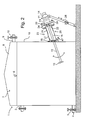
- eine dritte bevorzugte Ausführungsform eines erfindungsgemäßen Fördersystems, wiederum eingebaut in einen Gärbehälter und in Querschnittsdarstellung;
- Fig. 4
- eine schematische Darstellung des Fördersystems und eines Teilabschnitts des Gärbehälters der ersten bevorzugten Ausführungsform;
- Fig. 5
- eine schematische Darstellung des Fördersystems sowie eines Teilabschnitts des Gärbehälters der zweiten und dritten bevorzugten Ausführungsform in einer Teilexplosionsdarstellung;
- Fig. 6
- das Fördersystem und den Teilabschnitt des Gärbehälters gemäß
Fig. 5 in zusammengesetztem Zustand; - Fig. 6a
- das Fördersystem gemäß
Fig. 6 in einer weiteren möglichen Betriebsstellung, wiederum in einer schematischen Ansicht; und - Fig. 7
- eine weitere mögliche bevorzugte Ausführungsform eines erfindungsgemäßen Fördersystems.
- Zur Verdeutlichung ihrer Funktion und ihres Einsatzgebietes seien die erfindungsgemäßen Fördersysteme hauptsächlich in einem in einem Gär- bzw. Faulbehälter 1 eingebauten Zustand (
Fig. 1 bis 3 ) erläutert, während Details anhand derFig. 4 bis 7 erläutert seien. - Die erste bevorzugte Ausführungsform eines erfindungsgemäßen Fördersystems ist an einen Gär- bzw. Faulbehälter 1 (vgl.
Fig. 1 ) angebaut, welcher einen Prozessraum 2, in welchem die Biogaserzeugung stattfindet, sowie einen Einlass 3, welcher zur Befüllung, und einen Auslass 4, welcher zur Entleerung des Gärbehälters 1 dient, umfasst. Am Auslass 4 ist eine Absperrvorrichtung 5 in Form eines Schiebers angeordnet, welcher eine unerwünschte Entleerung des Behälters verhindert. Alternativ zu einem Schieber kann die Absperrvorrichtung 5 auch in Form eines Ventils, beispielsweise in Form eines Kugelventils oder eines Klappenventils vorliegen. Der Schieber ist manuell betätigbar, wobei auch eine automatisierte Betätigung auf elektrischem, pneumatischem oder hydraulischem Wege denkbar ist. - Der Prozessraum 2 ist bis zu einem Betriebsfüllstand 6 mit Gär- bzw. Faulstoffen 7 gefüllt, während oberhalb des Betriebsfüllstands 6 das anfallende Gas in einem Gasraum 8 gesammelt und über einen Gasauslass 9 seiner Verwendung zugeführt wird. Der Gasauslass 9 weist eine gasdichte Absperrvorrichtung 10 auf.
- Bei dem Behälter 1 kann es sich beispielsweise um einen Blechstau-, einen Kunststoff- oder einen gemauerten Behälter handeln, welcher ggf. eine entsprechende gasdichte Auskleidung besitzt. Im Bereich gemauerter Behälter kommen insbesondere Behälter aus Beton, welche entsprechende Kernbohrungen als Öffnungen aufweisen, in Frage.
- Das Fördersystem der ersten bevorzugten Ausführungsform, welches in
Fig. 1 in den Gärbehälter 1 integriert ist, weist eine Misch- bzw. Förderreinrichtung 11 auf, welche ein Misch- bzw. Förderelement in Form eines Propellers 12, eine Antriebswelle 13 sowie eine Antriebsvorrichtung in Form eines Motors 14 umfasst. Der Propeller 12 steht über die Antriebswelle 13 mit dem Motor 14 kraftschlüssig in Wirkeingriff. Der Kraftübertrag zwischen Motor 14 und Antriebswelle 13 kann beispielsweise über ein Getriebe oder eine anderweitige Antriebsmethode, insbesondere einen Ketten- oder Riemenantrieb erfolgen. An Stelle eines Propellers 12 als Förderelement ist selbstverständlich auch eine Schraube (beispielsweise eine schiffschraubenartig ausgebildete zwei- oder dreiblättrige Schraube), eine Schnecke oder dergleichen Vorrichtung denkbar. - Um eine gute Durchmischung der zu Gär- bzw. Faulstoffe 7 im Prozessraum 2 zu gewährleisten, ist die Misch- bzw. Fördereinrichtung 11 positionsveränderlich gegenüber dem Faul- bzw. Gärbehälter 1 angeordnet. In der vorliegenden bevorzugten Ausführungsform ist dabei vorgesehen, einen Teil der Fördervorrichtung 11, nämlich den Propeller 12 und Teile der Antriebswelle im Betriebszustand positionsveränderlich im Prozessraum 2 anzuordnen. In der Ausführungsform gemäß
Fig. 1 ist die Positionsveränderlichkeit dadurch realisiert, dass die Misch- bzw. Fördereinrichtung 11 in Richtung der Antriebswellenmittelachse verschieblich zum Gär- bzw. Faulbehälter 1 gelagert bzw. geführt ist, was für eine gute Durchmischung der Gär- bzw. Faulstoffe sorgt. In der vorliegenden bevorzugten Ausführungsform ist die Antriebswelle 13 im Bereich des Motors 14 in einem Schrägwellenlager gelagert, während sie weiter zum Gärbehälter 1 hin lediglich geführt ist (Führungsbuchse 21). Alternativ hierzu ist auch eine (ggf. weitere) Lagerung der Antriebswelle 13 im Bereich des Gärbehälters 1 denkbar. - Das Fördersystem umfasst weiterhin eine Kammer 15, welche teilweise durch eine Kammerwand 17 begrenzt ist. Ein zwischen der Kammer 15 und dem Prozessraum 2 angeordnetes Absperrelement in Form eines Schiebers 16 kann alternativ geöffnet oder geschlossen werden um die Kammer 15 mit dem Prozessraum 2 zu verbinden oder von letzterem flüssigkeitsdicht oder fluiddicht zu trennen. Aufgrund der Verschieblichkeit der Misch- bzw. Fördereinrichtung 11 ist es möglich, die Antriebswelle 13 mit dem daran befestigten Propeller 12 durch den geöffneten Schieber 16 hindurch in den Prozessraum 2 einzuführen und aus diesem in die Kammer 15 zurückzuziehen. Dies ermöglicht nach einem Schließen des Schiebers 16 einen einfachen Austausch des Propellers 12 und/oder weiterer Komponenten der Fördereinrichtung 11. Zum Zurückziehen des Propellers 12 in die Kammer 15 ist die Öffnung in der Behälterwand 18 und auch der lichte Querschnitt des Schiebers 16 derart ausgestaltet, dass der Propeller 12 durch die jeweilige Öffnung hindurchgeführt werden kann. Alternativ zum Schieber 16 sind auch anderweitige Absperrelemente wie beispielsweise ein Kugelventil, ein Klappenventil oder dergleichen denkbar. Die Verschieblichkeit der Fördereinrichtung 11 wird in der vorliegenden Ausführungsform durch Räder unterstützt, welche am Motor über entsprechende Stützelemente angebracht sind und z.B, auf Schienen (nicht dargestellt) verschiebbar geführt sind. Alternativ hierzu sind auch andere Verschiebemechanismen wie Hydraulikvorrichtungen o.ä. denkbar. Um einen zu harten Aufprall des Motors 14 der Fördereinrichtung 11 an einer Abschlussplatte 20 zu verhindern, sind Pufferelemente 46 am Motor 14 angebracht.
- Die Kammer 15 ist wie bereits vorstehend beschrieben auf ihrer einen Seite, nämlich der der Behälterwand zugewandten (Stirn-) Seite 18 durch den Schieber 16 begrenzt, während sie in radialer Richtung durch ein röhrenförmiges Element 19, welches die Kammerwand 17 bildet, begrenzt ist. Auf der dem Gärbehälter 1 abgewandten (Stirn-) Seite ist an dem röhrenförmigen Element 19 eine Abschlussplatte 20 angebracht, welche in der Mitte eine Aussparung zur Durchführung der Antriebswelle 13 aufweist. Die Antriebswelle 13 ist in der in die Abschlussplatte 20 integrierten Führungsbuchse 21 geführt, wobei ferner auf der dem Behälter zugewandten Seite eine ebenfalls in die Abschlussplatte 20 integrierte Dichtung (Antriebswellendichtung) in Form eines Simmerings 22 für die nötige Abdichtung sorgt. Alternativ oder zusätzlich zum Simmering 22 kann die Dichtung andere/weitere Dichtelemente wie z. B. eine Labyrinth-Dichtung, einen O-Ring, eine Dichtungsbuchse oder aber andere Dichtungselemente in Form einer Manschette aufweisen.
- Die bevorzugte Ausführungsform ist nochmals detailliert in
Fig.4 dargestellt. - Der Gärbehälter 1, in den die zweite bevorzugte Ausführungsform eines erfindungsgemäßen Fördersystems integriert ist (vgl.
Fig. 2 ), entspricht demjenigen, in den die erste Ausführungsform integriert ist. In der Folge sei deshalb auf die Unterschiede zwischen der ersten und der zweiten bevorzugten Fördersystem-Ausführungsform eingegangen. - Beim Fördersystem gemäß der zweiten bevorzugten Ausführungsform ist neben einer Verschieblichkeit des Propellers 12 entlang der Antriebswellenmittelachse zusätzlich eine Schwenkbarkeit desselben relativ zum Gärbehälter 1 gegeben. Dadurch kann die Durchmischung der Gärstoffe nochmals verbessert werden. Der Schwenkbereich der Misch- bzw. Fördereinrichtung 11 in vertikaler Richtung liegt in einem Schwenkwinkelintervall von 20° bis 30° (von einer Horizontalen nach unten gerichtet). Als Schwenkwinkel ist dabei der Winkel definiert, den die Antriebswellenmittelachse mit einer gedachten horizontalen Linie einschließt.
- In der zweiten bevorzugten Ausführungsform wird die Kammer 15 durch eine Befestigungsvorrichtung 23 gebildet, an welcher die Fördereinrichtung 11 befestigt ist und welche selbst wiederum am Gärbehälter 1 befestigt ist. Diese umfasst ein Zwischenelement in Form einer Zwischenplatte 24 sowie ein Anschlusselement 25, welches an seiner dem Gärbehälter 1 abgewandten Seite an der Zwischenplatte 24 befestigt ist und an seiner dem Gärbehälter 1 zugewandten Seite am Gärbehälter 1 selbst bzw. dessen Wand 18 befestigt bzw. befestigbar ist. Die Zwischenplatte 24 weist analog zu der Abschlussplatte 20 eine Führungsbuchse 21 auf, in welcher die Antriebswelle 13 geführt ist. Als Dichtungselement ist ebenfalls analog zur ersten bevorzugten Ausführungsform ein Simmering 22 vorhanden, wobei auf die Alternativen, die im Zusammenhang mit der ersten bevorzugten Ausführungsform erwähnt werde, verwiesen sei. Die Zwischenplatte 24 ist auf ihrer dem Gärbehälter 1 abgewandten Seite mit dem Motor 14 mit Befestigungselementen in Form von z.B. Schrauben 29 (alternativ können Bolzen oder andersartige Befestigungselemente Verwendung finden) verbunden, während sie auf ihrer dem Gärbehälter 1 zugewandten Seiten mit dem Anschlusselement 25 verbunden, vorzugsweise verschraubt ist.
- Das Anschlusselement 25 setzt sich aus einem röhren- bzw. schlauchartigen Abschnitt 26, einem aus einem Faltenbalg 27 bestehenden Abschnitt sowie dem Schieber 16 zusammen. Der Faltenbalg 27 ist aus einem geeigneten, gärstoffbeständigen Kunststoff (alternativ aus einem geeigneten Metall) gefertigt und mit dem bereits aus der ersten bevorzugten Ausführungsform bekannten Schieber 16 verbunden. Es sei an dieser Stelle angemerkt, dass an Stelle des Faltenbalgs auch ein anderes flexibles Element, beispielsweise ein schlauchartiges Element, denkbar wäre.
- Für eine korrekte Einstellung des Schwenkwinkels gegenüber der Horizontalen weist die zweite bevorzugte Ausführungsform eine verstellbare Stütze für die Fördereinrichtung 11 in Form einer Gewindespindel 28 auf. Dadurch kann der gewünschte Schwenkwinkel in einer einfachen Art und Weise realisiert werden. Alternativ hierzu wären auch eine Hydraulikvorrichtung (vgl. hierzu auch
Fig. 3 ) oder eine andere (verstellbare) Stützvorrichtung denkbar. - In der zweiten bevorzugten Ausführungsform ist neben der Herausnehmbarkeit bzw. Rückziehbarkeit des Förderelements 12 in die Kammer 15, wie bereits vorstehend erwähnt, für eine bessere Durchmischung (aufgrund der Verschieblichkeit und einer zusätzlichen Schwenkbarkeit des Förderelements) gesorgt. Während im Betrieb durch eine Längsverschieblichkeit und Schwenkbarkeit durch den Faltenbalg 27 eind optimale Durchmischung ermöglicht wird, besteht nach einem Lösen der Schrauben 29 die Möglichkeit, die Misch- bzw. Fördereinrichtung 11 von der Befestigungsvorrichtung 23 zu trennen und den Propeller 12 danach in die Kammer 15, welche durch die Zwischenplatte 24, das Anschlusselement 25 und den Schieber 16 begrenzt ist, zurückzuziehen. Nach dem Zurückziehen kann der Schieber 16 flüssigkeitsdicht bzw. in einer weiteren bevorzugten Ausführungsform fluiddicht geschlossen werden. Einem einfachen Austausch des Misch- bzw. Förderelements 12 oder der gesamten Misch- bzw. Fördereinrichtung 11 durch ein Abflanschen der Zwischenplatte 24 (bzw. in der ersten bevorzugten Ausführungsform der Abschlussplatte 20) steht nichts mehr entgegen. Um eine Entleerung der Kammer 15 vor dem Abflanschen zu ermöglichen, weist die Befestigungsvorrichtung einen verschliessbaren Auslass 47 auf, welcher ein Ablassen der in der Kammer befindlichen Gärstoffe ermöglicht. Auch die anderen bevorzugten Ausführungsformen können einen solchen Auslass 47 aufweisen.
- In Zusammenhang mit der zweiten bevorzugten Ausführungsform sei auf die
Figuren 5 bis 7 verwiesen. Wie ausFig. 5 hervorgeht, kann sowohl nur die Zwischenplatte 24 mit dem Motor mittels der Schrauben 29 verschraubt sein, während aber auch eine durchgehende Verschraubung von Anschlusselement 25, Zwischenplatte 24 und Motor 14 denkbar ist. Das Anschlusselement kann (ggf. zusätzlich zu den Schrauben 29) mit Befestigungselementen in Form von Schrauben 29a an der Zwischenplatte 24 befestigt sein. - In den
Figuren 6 und 6a ist die Misch- bzw. Fördereinrichtung 11 gemäßFig. 5 in zusammengebautem Zustand sowohl mit gestrecktem (Fig. 6 ) als auch mit komprimiertem (Fig. 6a ) Faltenbalg dargestellt. AusFig. 7 letztendlich kann man ersehen, dass die Position des Schiebers auch zwischen dem röhren- bzw. schlauchartigen Abschnitt 26 und dem Faltenbalg 27 denkbar ist. - Es sei an dieser Stelle angemerkt, dass der Grundgedanke der Erfindung nicht nur die Bereitstellung eines Fördersystems, sondern auch die Bereitstellung eines vollständigen Gär- bzw. Faulbehälter mit einem erfindungsgemäßen Fördersystem umfasst.
- In einer bevorzugten Ausführungsform eines Gärbehälters 1 (vgl.
Fig. 3 ) weist das Fördersystem nahezu alle Merkmale der aus derFig. 2 bekannten Ausführungsform auf, mit der Ausnahme, dass anstatt der Gewindespindel 28 ein Hydraulikelement 28a zur Abstützung der Misch- bzw. Fördereinrichtung 11 dient. Der Gärbehälter 1 weist jedoch zusätzlich zu den bereits aus den ausFig. 2 bekannten Merkmalen eine zweite Fördereinrichtung 30 auf, welche einen Haupt-Gär- bzw. Faulstoffkreislauf definiert, in welchem die in dem Gär- bzw. Faulbehälter 1 befindlichen Gär- bzw. Faulstoffe durch die zweite Fördereinrichtung 30 zirkuliert werden. Die Misch- bzw. Fördereinrichtung 11, welche zusätzlich zu der zweiten Fördereinrichtung 30 angebracht ist, dient in der vorliegenden bevorzugten Ausführungsform hauptsächlich der Auflösung von unerwünschten Materialansammlungen und der Durchmischung von schlecht durchmischten Bereichen. - Die zweite Misch- bzw. Fördereinrichtung 30 weist ein Misch- bzw. Förderelement in Form eines Propellers 31, eine Antriebswelle 32 sowie eine Antriebseinheit in Form eines Motors 33 auf. Der Propeller 31 steht über die Antriebswelle 32 mit dem Motor 33 kraftschlüssig in Wirkeingriff. In der beschriebenen bevorzugten Ausführungsform erfolgt der Kraftübertrag zwischen Motor 33 und Antriebswelle 32 über ein Getriebe 34. Alternativ hierzu ist selbstverständlich jegliche andere Antriebsmethode, insbesondere ein Ketten- oder Riemenantrieb, denkbar.
- Analog zur Misch- bzw. Fördereinrichtung 11 kann auch bei der zweiten Misch- bzw. Fördereinrichtung 30 an die Stelle eines Propellers 31 als Förderelement eine Schraube (beispielsweise eine schiffschraubenartig ausgebildete Schraube) oder dergleichen Vorrichtung treten. Ferner kann die zweite Fördereinrichtung 30 nicht nur, wie vorstehend beschrieben, ein so genanntes Rührwerk sein, sondern auch eine Pumpe, insbesondere eine Schneckenpumpe, Kreiselpumpe oder eine anderweitige Pumpe, welche aufgrund einer rotatorischen Bewegung eine Förderleistung erzielt bzw. welche auf einem rotatorischen Prinzip beruht.
- Durch die zweite Fördereinrichtung 30 wird ein Gär- bzw. Faulstoff-Kreislauf definiert, welcher der gleichmäßigen Verteilung der Gär- bzw. Faulstoffe, welche insbesondere Abfallstoffe und nachwachsende Rohstoffe umfassen können, und einer kontinuierlichen Entgasung derselben bzw. des Gärbehälters 1 dient.
- Die Vermischung erfolgt hauptsächlich mittels der zweiten Fördereinrichtung 30, welche zumindest teilweise die am Einlass 3 eintretenden Gärstoffe über eine Öffnung 35 in ein mit dieser Öffnung in Fluidverbindung stehendes Rohr 36 saugt. Die Öffnung 35 ist in einem oberen Bereich des Gärbehälters 1 bzw. des Prozessraums 2 (der Mittelpunkt der Öffnung befindet sich auf Höhe von 80 % - 90 % des Betriebsfüllstandes 6 des Gärbehälters 1) in der Nähe des Einlasses 3 angeordnet. Das Rohr 36 ist in etwa n-förmig ausgebildet, wobei der nach oben gewandte Schenkel 36 a des Rohres 36 mit dem senkrechten Abschnitt 36 b des Rohres 36 einen Winkel von größer 90° (in etwa 100° bis 110°) einschließt. Der Gärstoff, welcher durch die Öffnung 35 eingesaugt wird, wird über einen unteren Schenkel 36 c des Rohres 36, in welchem der Propeller 31 angeordnet ist, über diesen in eine im Gärbehälter angeordnete Öffnung 37, in welche der untere Schenkel 36 c des Rohres 36 hineinragt, eingespeist.
- Der untere Schenkel 36 c des Rohres 36 ist in der Öffnung 37 im Behälter 1 mittels eines Kugelgelenks 38 beweglich bzw. schwenkbar gelagert. Dadurch ist der Winkel, unter dem die Gär- bzw. Faulstoffe bezüglich des Behälterbodens eingeleitet werden, variabel, sodass alle gewünschten Strömungsverhältnisse herstellbar sind. An Stelle des Kugelgelenks 38 sind auch eine entsprechende Blendenanordnung, Düsenanordnung oder jegliche andere die Strömung leitende Vorrichtung denkbar. Dadurch entsteht die gewünschte Durchmischung der Gärstoffe in einem Kreislauf, welcher von der Öffnung 35 über das Rohr 36 hin zur Öffnung 37 und dort über eine Zirkulation bzw. Strömung im Prozessraum 2 wieder zur Öffnung 35 führt. Der Gärbehälter 1 weist also in anderen Worten gesagt einen außerhalb des Prozessraums 2 angeordneten Abschnitt 39 des Gärstoff-Kreislaufs auf, welcher im Wesentlichen durch das Rohr 36 sowie Teile der zweiten Fördereinrichtung 30 (Teile der Antriebswelle 32 sowie insbesondere den Propeller 31) definiert wird. Der Mittelpunkt der Öffnung 37 befindet sich auf Höhe von 5 % - 20 % des Betriebsfüllstandes 6 des Gärbehälters 1.
- Die zweite Fördereinrichtung 30 ist teilweise, sowohl in Form des Propellers 31 als auch in Form eines Abschnitts der Antriebswelle 32 in dem außerhalb des Prozessraums 2 angeordneten Kreislaufabschnitt 39, nämlich im Schenkel 36 c des Rohres 36, angeordnet. Bei alternativen bevorzugten Ausführungsformen können analog zur hier beschriebenen bevorzugten Ausführungsform beispielsweise anstelle des Propellers 31 als Misch- bzw. Förderelement eine Schraube, insbesondere eine dreiblättrige Schraube (ähnlich einer Schiffschraube) oder ein Pumpelement, beispielsweise die Schnecke einer Schneckenpumpe bzw. eine Kreiselpumpe im Kreislaufabschnitt 39 angeordnet sein. Alternativ ist es auch denkbar, dass die gesamte zweite Fördereinrichtung 30 im Kreislaufabschnitt 39 angeordnet ist. Alternativ zur Anordnung im Schenkel 36 c kann die zweite Fördereinrichtung 30 bzw. können Teile der zweiten Fördereinrichtung 30 auch in anderen Bereichen des Rohres 36 angeordnet sein (insbesondere im Schenkel 36 a oder im Abschnitt 36 b).
- Im Rohr 36 sind in einem dem unteren Schenkel 36 c zugewandten Bereich des senkrechten Abschnitts 36 b des Rohres 36 sowie in einem der Öffnung 37 zugewandten Bereich des unteren Schenkels 36 c des Rohres 36 zwei Absperreinrichtungen 40, 41 in Form von Schiebern, insbesondere Plattenschiebern, Doppelplattenschiebern oder Brillenschiebern angeordnet, durch deren Schließen es ermöglicht wird, die zweite Fördereinrichtung 30, insbesondere das Förderelement 31 zu reparieren bzw. dieselbe bzw. dasselbe auszuwechseln, während der Prozessraum 2 des Gärbehälters 1 mit Gärstoffen bzw. Substrat gefüllt bleiben kann. Auch hier wären als Alternativen zu Schiebern Ventile, insbesondere Kugelventile bzw. Klappenventile mit einer oder mehreren Klappen denkbar.
- Die Antriebsvorrichtung (Motor 33), welche die Antriebswelle 32 antreibt, ist über einen Flansch 42 an das Rohr 36 angeflanscht. Im Bereich des Flansches 42 ist die Antriebswelle 32 mittels geeigneter Lager, beispielsweise Rollen- bzw. Kugellager gelagert und mittels einer Dichtung fluiddicht gegen die Umgebung bzw. gegen den Motor 33 abgedichtet. Sowohl der Motor 33 als auch der außen liegende Kreislaufabschnitt sind fest im Boden verankert. Hierzu finden Verankerungselemente in Verbindung mit passenden Stützen Verwendung.
- Für eine nötige Entleerung eines Volumens 43, welches im Rohr 36 durch die beiden Absperrvorrichtungen 40, 41 definiert ist, weist der untere Schenkel 36 c des Rohres 36 einen Auslass 44 auf, welcher mittels einer Absperrvorrichtung 45, die in der hier beschriebenen bevorzugten Ausführungsform in Form eines Schiebers vorliegt, verschlossen ist. Bei einem Austausch bzw. einer Reparatur der zweiten Fördereinrichtung 30 bzw. des Förderelements können die im Volumen 43 befindlichen Gärstoffe durch den Auslass 44 abgelassen werden. Der Auslass 20 ist in etwa an der am tiefsten liegenden Stelle des außen liegenden Kreislaufabschnitts 39 bzw. an der tiefstliegenden Stelle des Volumens 43 angebracht, um eine sichere Entleerung bei einer Reparatur der zweiten Fördereinrichtung 30 gewährleisten zu können. Auch die Absperrvorrichtung 45 liegt in der bevorzugten Ausführungsform in Form eines Schiebers vor, wobei hier an Stelle eines Schiebers jegliche andere Absperrvorrichtung, insbesondere in Form eines Ventils, beispielsweise eines Kugelventils oder Klappenventils, denkbar wäre. Alternativ oder zusätzlich zur Absperrvorrichtung 45 kann der Auslass 44 mit einer Verschlusskappe, welche fluiddicht schließt, versehen sein.
- Es sei an dieser Stelle angemerkt, dass sämtliche Absperreinrichtungen teilweise, d.h. an den Teilen, an denen sie mit den Gärstoffen in Verbindung kommen, mit einem Korrosionsschutz in Form einer keramischen Beschichtung versehen sind. Alternativ hierzu kommt selbstverständlich auch eine Herstellung der mit den Gärstoffen in Verbindung stehenden Teile der Absperrvorrichtung aus einem korrosionsbeständigen Material, beispielsweise einer Keramik oder geeigneten Stählen, insbesondere Edelstählen oder Kunststoffen, in Frage. Auch eine Herstellung der gesamten Absperreinrichtung(en) aus korrosionsbeständigem Material bzw. eine vollständige Beschichtung der Absperreinrichtungen ist denkbar.
- Es bleibt noch anzumerken, dass zur einfachen Entleerung des Volumens 43 die Absperreinrichtung 40 oberhalb bzw. stromaufwärts des Propellers 31 angeordnet ist, während die Absperreinrichtung 41 stromabwärts des Propellers 31 angeordnet ist. Die Begriffe "stromaufwärts" und "stromabwärts" beziehen sich dabei auf den normalen Betrieb der Anlage (entgegen dem Uhrzeigersinn), wobei angemerkt sei, dass die Anlage auch im umgekehrten Sinne (im Uhrzeigersinn) betrieben werden kann. Dies ist insbesondere notwendig, um eventuelle Blockaden bzw. Verstopfungen im Rohr 36 zu beseitigen. Auch für eine bessere Gasabfuhr kommt ein Betrieb entgegen der herkömmlichen Richtung in Frage.
- Obwohl die Erfindung anhand einer Ausführungsform mit fester Merkmalskombination beschrieben wird, umfasst sie jedoch auch die denkbaren weiteren vorteilhaften Kombinationen wie sie insbesondere, aber nicht erschöpfend, durch die Unteransprüche angegeben sind. Sämtliche in den Anmeldungsunterlagen offenbarten Merkmale werden als erfindungswesentlich beansprucht, soweit sie einzeln oder in Kombination gegenüber dem Stand der Technik neu sind.
Claims (13)
- Fördersystem eines Gär- bzw. Faulbehälters (1), welches eine Fördereinrichtung (11) umfasst, welche eine Antriebsvorrichtung (14), eine Antriebswelle (13) und ein Förderelement (12) aufweist,
dadurch gekennzeichnet,
dass das Fördersystem weiterhin eine Kammer umfasst, in welche das Förderelement (12) rückziehbar bzw. einführbar ist, und welche nach einem Rückziehen bzw. Einführen des Förderelements (12) flüssigkeits- oder fluiddicht abschließbar ist. - Fördersystem nach Anspruch 1,
dadurch gekennzeichnet,
dass die Kammer (15) eine Kammerwand (17) aufweist, die eine Befestigungseinrichtung zur Befestigung an einer Wand (18) eines Gär- bzw. Faulbehälters (1) aufweist. - Fördersystem nach Anspruch 1 oder Anspruch 2,
dadurch gekennzeichnet,
dass an der Kammer (15) ein Absperrelement (16) angeordnet ist, welches alternativ geöffnet oder geschlossen werden kann, um die Kammer (15) zu öffnen oder flüssigkeitsdicht oder fluiddicht abzuschließen. - Fördersystem nach einem der vorhergehenden Ansprüche,
dadurch gekennzeichnet,
dass die Antriebswelle (13) mit dem daran befestigten Förderelement (12) durch das geöffnete Absperrelement (16) hindurch in die Kammer (15) einführbar und aus dieser herausführbar ist. - Fördersystem nach einem der vorhergehenden Ansprüche,
dadurch gekennzeichnet,
dass die Kammer wenigstens teilweise durch eine Befestigungsvorrichtung (23) welche an einem Gär- bzw. Faulbehälter (1) befestigbar ist, gebildet wird, welche ein Zwischenelement (24), welches an der Fördereinrichtung (11) angebracht ist, und ein Anschlusselement (25) aufweist, welches einerseits an dem Zwischenelement (24) angebracht und andererseits dazu ausgebildet ist, an einem/dem Gär- bzw. Faulbehälter (1) angebracht zu werden. - Fördersystem nach Anspruch 5,
dadurch gekennzeichnet,
dass das Zwischenelement (24) eine Zwischenplatte ist und eine Führungsbuchse (21) aufweist, welche vorzugsweise aus Kunststoff gefertigt ist, und in welcher die Antriebswelle (13) der Fördereinrichtung (11) gelagert oder geführt ist. - Fördersystem nach einem der Ansprüche 5 oder 6,
dadurch gekennzeichnet,
dass das Zwischenelement (24) eine Dichtung (22), insbesondere einen Simmering aufweist, welcher vorzugsweise auf einer der Fördereinrichtung (11) abgewandten Seite des Zwischenelements (24) angeordnet ist. - Fördersystem nach einem der Ansprüche 5 bis 7,
dadurch gekennzeichnet,
dass das Anschlusselement (25) wenigstens ein flexibles Element, insbesondere ein schlauchartiges Element aufweist. - Fördersystem nach einem der vorhergehenden Ansprüche,
dadurch gekennzeichnet,
dass die Fördereinrichtung (11) eine verstellbare Stütze, insbesondere eine Gewindespindel (28) oder eine Hydraulikanordnung (28a) aufweist. - Gär- bzw. Faulbehälter (1), insbesondere für Biogas-Anlagen bzw. biologische Kläranlagen, mit einem Prozessraum (2), einem Einlass (3) und einem Auslass (4),
dadurch gekennzeichnet,
dass der Gär- bzw. Faulbehälter (1) weiterhin ein Fördersystem nach einem der vorangehenden Ansprüche umfasst. - Gär- bzw. Faulbehälter (1) nach Anspruch 10,
dadurch gekennzeichnet,
dass die Kammer (15) des Fördersystems außerhalb des Prozessraums (2) angeordnet ist. - Gär- bzw. Faulbehälter (1) nach einem der vorhergehenden Ansprüche 10 oder 11,
dadurch gekennzeichnet,
dass der Faul- bzw. Gärbehälter (1) eine zweite Fördereinrichtung (30) aufweist, welche einen Haupt-Gär- bzw. Faulstoffkreislauf definiert, in welchem in dem Gär- bzw. Faulbehälter (1) befindliche Gär- bzw. Faulstoffe durch die zweite Fördereinrichtung (30) zirkuliert werden. - Gär- bzw. Faulbehälter (1) nach Anspruch 12,
dadurch gekennzeichnet,
dass der Gär- bzw. Faulbehälter (1) einen außerhalb des Prozessraums (2) angeordneten Kreislaufabschnitt (39) aufweist und die zweite Fördereinrichtung (30) wenigstens teilweise in dem außerhalb des Prozessraums (2) angeordneten Kreislaufabschnitt (39) angeordnet ist.
Applications Claiming Priority (1)
| Application Number | Priority Date | Filing Date | Title |
|---|---|---|---|
| DE102007022902A DE102007022902A1 (de) | 2007-05-14 | 2007-05-14 | Fördersystem eines Gär- bzw. Faulbehälters |
Publications (2)
| Publication Number | Publication Date |
|---|---|
| EP1992405A1 true EP1992405A1 (de) | 2008-11-19 |
| EP1992405B1 EP1992405B1 (de) | 2009-05-20 |
Family
ID=39672915
Family Applications (1)
| Application Number | Title | Priority Date | Filing Date |
|---|---|---|---|
| EP08103822A Active EP1992405B1 (de) | 2007-05-14 | 2008-05-05 | Fördersystem eines Gär- bzw. Faulbehälters |
Country Status (3)
| Country | Link |
|---|---|
| EP (1) | EP1992405B1 (de) |
| AT (1) | ATE431756T1 (de) |
| DE (2) | DE102007022902A1 (de) |
Cited By (9)
| Publication number | Priority date | Publication date | Assignee | Title |
|---|---|---|---|---|
| EP2193837A2 (de) | 2008-12-07 | 2010-06-09 | Thürwachter Gmbh & Co.KG | Rührwerk |
| WO2011082787A1 (de) | 2009-12-16 | 2011-07-14 | Mt-Energie Gmbh | Behälter einer biogasanlage sowie verfahren zur entnahme einer komponente aus dem behälter |
| NL2004534C2 (en) * | 2010-04-12 | 2011-10-13 | Colsen | Homogeneity device for a tank, use thereof and assembly of a tank and said device. |
| EP2441511A1 (de) * | 2010-10-13 | 2012-04-18 | SPX Corporation | Vorrichtung und Verfahren zum synchronisierten Mischen |
| US20120164720A1 (en) * | 2010-12-23 | 2012-06-28 | Johann Bierer | Biogas plant and service device for a biogas plant |
| EP2361673A3 (de) * | 2010-02-21 | 2013-01-02 | Thürwächter Gmbh & Co.KG | Vorrichtung |
| EP2826725A1 (de) * | 2013-07-15 | 2015-01-21 | SPX Corporation | Einziehbare Mischvorrichtung und Verfahren |
| DE102015106419A1 (de) * | 2015-04-27 | 2016-10-27 | Stefan Steverding Sondermaschinen- und Vorrichtungsbau GmbH | Rührwerk und Behälter mit Rührwerk |
| DE102015011881A1 (de) * | 2015-09-10 | 2017-03-16 | Sartorius Stedim Biotech Gmbh | Mischsystem und Verfahren zum Mischen eines Fluids und/oder eines Feststoffs |
Families Citing this family (2)
| Publication number | Priority date | Publication date | Assignee | Title |
|---|---|---|---|---|
| DE102011081431A1 (de) | 2011-08-23 | 2013-02-28 | Lipp Gmbh | Gär- oder Faulbehälter mit Einbauschacht sowie Montageeinheit und Verfahren zur Montage und Demontage eines Rührwerks |
| CN116116295A (zh) * | 2022-12-21 | 2023-05-16 | 山西能投生物质能开发利用股份有限公司 | 大型沼气工程原料储存混合输送装置 |
Citations (7)
| Publication number | Priority date | Publication date | Assignee | Title |
|---|---|---|---|---|
| CH129230A (de) * | 1927-10-17 | 1928-12-01 | Albert Schnelli | Rührwerk an Jauchegruben. |
| DE2855206A1 (de) * | 1978-12-21 | 1980-06-26 | Hoelz Otto Masch Gmbh | Ruehrgeraete fuer fluessigmist und abwasser |
| DE8714525U1 (de) * | 1987-10-31 | 1988-01-28 | Guenter Schmarje Stalltechnik, Landmaschinen, 2161 Wischhafen, De | |
| US4836687A (en) * | 1986-04-16 | 1989-06-06 | Oliver A. Kardoes | Waste pit stirrer |
| DE9404188U1 (de) | 1994-03-12 | 1994-06-01 | Klein Schanzlin & Becker Ag | Mischeinrichtung für flüssigkeitsgefüllte Behälter |
| DE19756485A1 (de) | 1997-12-18 | 1999-07-01 | Xaver Lipp | Faulbehälter mit Rührwerk und Verfahren zum Betreiben eines Rührwerks in einem Faulbehälter |
| EP1932902A1 (de) * | 2006-12-12 | 2008-06-18 | Karl Buschmann Maschinenbau GmbH | Gär- bzw. Faulbehälter |
Family Cites Families (2)
| Publication number | Priority date | Publication date | Assignee | Title |
|---|---|---|---|---|
| DE20106837U1 (de) * | 2001-04-19 | 2001-08-02 | Uts Umwelt Technik Sued Gmbh | Feststoff-Zudosier-Vorrichtung an einem Fermenter einer Biogasanlage |
| DE10318298A1 (de) * | 2003-04-15 | 2004-11-11 | Xaver Lipp | Vorrichtung zum Einspritzen einer im wesentlichen flüssigen Substanz in einen Behälter, sowie Behälter mit einer solchen Vorrichtung |
-
2007
- 2007-05-14 DE DE102007022902A patent/DE102007022902A1/de not_active Withdrawn
-
2008
- 2008-05-05 AT AT08103822T patent/ATE431756T1/de active
- 2008-05-05 EP EP08103822A patent/EP1992405B1/de active Active
- 2008-05-05 DE DE502008000024T patent/DE502008000024D1/de active Active
Patent Citations (7)
| Publication number | Priority date | Publication date | Assignee | Title |
|---|---|---|---|---|
| CH129230A (de) * | 1927-10-17 | 1928-12-01 | Albert Schnelli | Rührwerk an Jauchegruben. |
| DE2855206A1 (de) * | 1978-12-21 | 1980-06-26 | Hoelz Otto Masch Gmbh | Ruehrgeraete fuer fluessigmist und abwasser |
| US4836687A (en) * | 1986-04-16 | 1989-06-06 | Oliver A. Kardoes | Waste pit stirrer |
| DE8714525U1 (de) * | 1987-10-31 | 1988-01-28 | Guenter Schmarje Stalltechnik, Landmaschinen, 2161 Wischhafen, De | |
| DE9404188U1 (de) | 1994-03-12 | 1994-06-01 | Klein Schanzlin & Becker Ag | Mischeinrichtung für flüssigkeitsgefüllte Behälter |
| DE19756485A1 (de) | 1997-12-18 | 1999-07-01 | Xaver Lipp | Faulbehälter mit Rührwerk und Verfahren zum Betreiben eines Rührwerks in einem Faulbehälter |
| EP1932902A1 (de) * | 2006-12-12 | 2008-06-18 | Karl Buschmann Maschinenbau GmbH | Gär- bzw. Faulbehälter |
Cited By (15)
| Publication number | Priority date | Publication date | Assignee | Title |
|---|---|---|---|---|
| EP2193837A3 (de) * | 2008-12-07 | 2010-07-21 | Thürwachter Gmbh & Co.KG | Rührwerk |
| WO2010070447A3 (en) * | 2008-12-07 | 2010-08-12 | Suma Sondermaschinen Gmbh | Agitator |
| EP2193837A2 (de) | 2008-12-07 | 2010-06-09 | Thürwachter Gmbh & Co.KG | Rührwerk |
| WO2011082787A1 (de) | 2009-12-16 | 2011-07-14 | Mt-Energie Gmbh | Behälter einer biogasanlage sowie verfahren zur entnahme einer komponente aus dem behälter |
| EP2361673A3 (de) * | 2010-02-21 | 2013-01-02 | Thürwächter Gmbh & Co.KG | Vorrichtung |
| NL2004534C2 (en) * | 2010-04-12 | 2011-10-13 | Colsen | Homogeneity device for a tank, use thereof and assembly of a tank and said device. |
| EP2441511A1 (de) * | 2010-10-13 | 2012-04-18 | SPX Corporation | Vorrichtung und Verfahren zum synchronisierten Mischen |
| US20120164720A1 (en) * | 2010-12-23 | 2012-06-28 | Johann Bierer | Biogas plant and service device for a biogas plant |
| US9193945B2 (en) * | 2010-12-23 | 2015-11-24 | Uts Biogastechnik Gmbh | Biogas plant and service device for a biogas plant |
| EP2826725A1 (de) * | 2013-07-15 | 2015-01-21 | SPX Corporation | Einziehbare Mischvorrichtung und Verfahren |
| CN105080383A (zh) * | 2013-07-15 | 2015-11-25 | Spx流动有限公司 | 可伸缩的混合装置和方法 |
| AU2014203763B2 (en) * | 2013-07-15 | 2018-07-26 | Spx Flow, Inc. | Retractable mixing device and method |
| DE102015106419A1 (de) * | 2015-04-27 | 2016-10-27 | Stefan Steverding Sondermaschinen- und Vorrichtungsbau GmbH | Rührwerk und Behälter mit Rührwerk |
| DE102015011881A1 (de) * | 2015-09-10 | 2017-03-16 | Sartorius Stedim Biotech Gmbh | Mischsystem und Verfahren zum Mischen eines Fluids und/oder eines Feststoffs |
| DE102015011881B4 (de) | 2015-09-10 | 2019-05-29 | Sartorius Stedim Biotech Gmbh | Mischsystem und Verfahren zum Mischen eines Fluids und/oder eines Feststoffs |
Also Published As
| Publication number | Publication date |
|---|---|
| EP1992405B1 (de) | 2009-05-20 |
| ATE431756T1 (de) | 2009-06-15 |
| DE102007022902A1 (de) | 2008-11-20 |
| DE502008000024D1 (de) | 2009-07-02 |
Similar Documents
| Publication | Publication Date | Title |
|---|---|---|
| EP1992405B1 (de) | Fördersystem eines Gär- bzw. Faulbehälters | |
| EP1577376A2 (de) | Fermenter einer Biogasanlage mit einer Rühreinrichtung | |
| DE202011107750U1 (de) | Einbringschnecke für Biogasanlagen | |
| DE19648875B4 (de) | Fermenter für Biomasse | |
| DE202006020742U1 (de) | Fermenter einer Biogasanlage mit einer Rühreinrichtung | |
| EP1932902B1 (de) | Gär- bzw. Faulbehälter | |
| EP1619239B1 (de) | Biogasanlage zur Fermentation von organischen Stoffen | |
| DE102011114793A1 (de) | Verfahren und Anlage zur Herstellung von Biogassubstrat in Anmaischbehältern | |
| EP1362635A1 (de) | Rühreinrichtung für einen Fermenter einer Biogasanlage | |
| EP3065852B1 (de) | Rührwerk zum mischen von fluiden | |
| EP2513285B1 (de) | Behälter einer biogasanlage sowie verfahren zur entnahme einer komponente aus dem behälter | |
| EP1876229A1 (de) | Biogasanlage zur Fermentation von organischen Stoffen | |
| DE102010000489B4 (de) | Vorrichtung | |
| DE102009056967A1 (de) | Mischvorrichtung | |
| EP2914709B1 (de) | Fermenter einer biogasanlage | |
| DE10252527B4 (de) | Vorrichtung zur Einbringung von trockenen organischen Stoffen in einen Vergärungsbehälter einer Biogasanlage | |
| EP1394246A1 (de) | Rühreinrichtung für einen Fermenter einer Biogasanlage sowie Verfahren zur Verteilung von Biomasse in einer Fermenterflüssigkeit mit einer Rühreinrichtung | |
| DE4416521A1 (de) | Pfropfstrombetriebener Fermenter mit einem Rührwerk | |
| WO2009000900A2 (de) | Fermentationsanlage | |
| DE3345643A1 (de) | Vorrichtung zum aufbereiten von vorzugsweise in behaeltern befindlichen fluessigkeiten, insbesondere von guelle | |
| EP3516037B1 (de) | Behälter und biogasanlage | |
| EP2319286B1 (de) | Rührwerk und Verfahren zum Verrühren und Abpumpen Feststoffe enthaltender Flüssigkeiten | |
| DE3420094A1 (de) | Propellerruehrwerk | |
| DE102010050863B4 (de) | Vorrichtung zum Mischen von nicht pumpfähiger Biomasse mit einer Flüssigkeit | |
| DE3043540C2 (de) | Stehender Behälter für Traubenmaische |
Legal Events
| Date | Code | Title | Description |
|---|---|---|---|
| PUAI | Public reference made under article 153(3) epc to a published international application that has entered the european phase |
Free format text: ORIGINAL CODE: 0009012 |
|
| 17P | Request for examination filed |
Effective date: 20080913 |
|
| AK | Designated contracting states |
Kind code of ref document: A1 Designated state(s): AT BE BG CH CY CZ DE DK EE ES FI FR GB GR HR HU IE IS IT LI LT LU LV MC MT NL NO PL PT RO SE SI SK TR |
|
| AX | Request for extension of the european patent |
Extension state: AL BA MK RS |
|
| GRAP | Despatch of communication of intention to grant a patent |
Free format text: ORIGINAL CODE: EPIDOSNIGR1 |
|
| GRAS | Grant fee paid |
Free format text: ORIGINAL CODE: EPIDOSNIGR3 |
|
| GRAA | (expected) grant |
Free format text: ORIGINAL CODE: 0009210 |
|
| AK | Designated contracting states |
Kind code of ref document: B1 Designated state(s): AT BE BG CH CY CZ DE DK EE ES FI FR GB GR HR HU IE IS IT LI LT LU LV MC MT NL NO PL PT RO SE SI SK TR |
|
| REG | Reference to a national code |
Ref country code: GB Ref legal event code: FG4D Free format text: NOT ENGLISH |
|
| REG | Reference to a national code |
Ref country code: CH Ref legal event code: EP |
|
| REG | Reference to a national code |
Ref country code: IE Ref legal event code: FG4D Free format text: LANGUAGE OF EP DOCUMENT: GERMAN |
|
| REF | Corresponds to: |
Ref document number: 502008000024 Country of ref document: DE Date of ref document: 20090702 Kind code of ref document: P |
|
| AKX | Designation fees paid |
Designated state(s): AT BE BG CH CY CZ DE DK EE ES FI FR GB GR HR HU IE IS IT LI LT LU LV MC MT NL NO PL PT RO SE SI SK TR |
|
| PG25 | Lapsed in a contracting state [announced via postgrant information from national office to epo] |
Ref country code: LT Free format text: LAPSE BECAUSE OF FAILURE TO SUBMIT A TRANSLATION OF THE DESCRIPTION OR TO PAY THE FEE WITHIN THE PRESCRIBED TIME-LIMIT Effective date: 20090520 Ref country code: FI Free format text: LAPSE BECAUSE OF FAILURE TO SUBMIT A TRANSLATION OF THE DESCRIPTION OR TO PAY THE FEE WITHIN THE PRESCRIBED TIME-LIMIT Effective date: 20090520 Ref country code: ES Free format text: LAPSE BECAUSE OF FAILURE TO SUBMIT A TRANSLATION OF THE DESCRIPTION OR TO PAY THE FEE WITHIN THE PRESCRIBED TIME-LIMIT Effective date: 20090831 Ref country code: NO Free format text: LAPSE BECAUSE OF FAILURE TO SUBMIT A TRANSLATION OF THE DESCRIPTION OR TO PAY THE FEE WITHIN THE PRESCRIBED TIME-LIMIT Effective date: 20090820 |
|
| NLV1 | Nl: lapsed or annulled due to failure to fulfill the requirements of art. 29p and 29m of the patents act | ||
| PG25 | Lapsed in a contracting state [announced via postgrant information from national office to epo] |
Ref country code: SE Free format text: LAPSE BECAUSE OF FAILURE TO SUBMIT A TRANSLATION OF THE DESCRIPTION OR TO PAY THE FEE WITHIN THE PRESCRIBED TIME-LIMIT Effective date: 20090820 Ref country code: PL Free format text: LAPSE BECAUSE OF FAILURE TO SUBMIT A TRANSLATION OF THE DESCRIPTION OR TO PAY THE FEE WITHIN THE PRESCRIBED TIME-LIMIT Effective date: 20090520 Ref country code: NL Free format text: LAPSE BECAUSE OF FAILURE TO SUBMIT A TRANSLATION OF THE DESCRIPTION OR TO PAY THE FEE WITHIN THE PRESCRIBED TIME-LIMIT Effective date: 20090520 Ref country code: IS Free format text: LAPSE BECAUSE OF FAILURE TO SUBMIT A TRANSLATION OF THE DESCRIPTION OR TO PAY THE FEE WITHIN THE PRESCRIBED TIME-LIMIT Effective date: 20090920 Ref country code: LV Free format text: LAPSE BECAUSE OF FAILURE TO SUBMIT A TRANSLATION OF THE DESCRIPTION OR TO PAY THE FEE WITHIN THE PRESCRIBED TIME-LIMIT Effective date: 20090520 Ref country code: SI Free format text: LAPSE BECAUSE OF FAILURE TO SUBMIT A TRANSLATION OF THE DESCRIPTION OR TO PAY THE FEE WITHIN THE PRESCRIBED TIME-LIMIT Effective date: 20090520 |
|
| REG | Reference to a national code |
Ref country code: IE Ref legal event code: FD4D |
|
| PG25 | Lapsed in a contracting state [announced via postgrant information from national office to epo] |
Ref country code: IE Free format text: LAPSE BECAUSE OF FAILURE TO SUBMIT A TRANSLATION OF THE DESCRIPTION OR TO PAY THE FEE WITHIN THE PRESCRIBED TIME-LIMIT Effective date: 20090520 Ref country code: DK Free format text: LAPSE BECAUSE OF FAILURE TO SUBMIT A TRANSLATION OF THE DESCRIPTION OR TO PAY THE FEE WITHIN THE PRESCRIBED TIME-LIMIT Effective date: 20090520 Ref country code: EE Free format text: LAPSE BECAUSE OF FAILURE TO SUBMIT A TRANSLATION OF THE DESCRIPTION OR TO PAY THE FEE WITHIN THE PRESCRIBED TIME-LIMIT Effective date: 20090520 Ref country code: CZ Free format text: LAPSE BECAUSE OF FAILURE TO SUBMIT A TRANSLATION OF THE DESCRIPTION OR TO PAY THE FEE WITHIN THE PRESCRIBED TIME-LIMIT Effective date: 20090520 Ref country code: RO Free format text: LAPSE BECAUSE OF FAILURE TO SUBMIT A TRANSLATION OF THE DESCRIPTION OR TO PAY THE FEE WITHIN THE PRESCRIBED TIME-LIMIT Effective date: 20090520 |
|
| PG25 | Lapsed in a contracting state [announced via postgrant information from national office to epo] |
Ref country code: SK Free format text: LAPSE BECAUSE OF FAILURE TO SUBMIT A TRANSLATION OF THE DESCRIPTION OR TO PAY THE FEE WITHIN THE PRESCRIBED TIME-LIMIT Effective date: 20090520 Ref country code: HR Free format text: LAPSE BECAUSE OF FAILURE TO SUBMIT A TRANSLATION OF THE DESCRIPTION OR TO PAY THE FEE WITHIN THE PRESCRIBED TIME-LIMIT Effective date: 20090520 |
|
| PLBI | Opposition filed |
Free format text: ORIGINAL CODE: 0009260 |
|
| PLAX | Notice of opposition and request to file observation + time limit sent |
Free format text: ORIGINAL CODE: EPIDOSNOBS2 |
|
| 26 | Opposition filed |
Opponent name: MT-ENERGIE GMBH & CO. KG Effective date: 20100119 |
|
| PG25 | Lapsed in a contracting state [announced via postgrant information from national office to epo] |
Ref country code: BG Free format text: LAPSE BECAUSE OF FAILURE TO SUBMIT A TRANSLATION OF THE DESCRIPTION OR TO PAY THE FEE WITHIN THE PRESCRIBED TIME-LIMIT Effective date: 20090820 |
|
| PLAF | Information modified related to communication of a notice of opposition and request to file observations + time limit |
Free format text: ORIGINAL CODE: EPIDOSCOBS2 |
|
| PLBB | Reply of patent proprietor to notice(s) of opposition received |
Free format text: ORIGINAL CODE: EPIDOSNOBS3 |
|
| BERE | Be: lapsed |
Owner name: KARL BUSCHMANN MASCHINENBAU G.M.B.H. Effective date: 20100531 |
|
| PG25 | Lapsed in a contracting state [announced via postgrant information from national office to epo] |
Ref country code: MC Free format text: LAPSE BECAUSE OF NON-PAYMENT OF DUE FEES Effective date: 20100531 |
|
| REG | Reference to a national code |
Ref country code: FR Ref legal event code: ST Effective date: 20110131 |
|
| PG25 | Lapsed in a contracting state [announced via postgrant information from national office to epo] |
Ref country code: BE Free format text: LAPSE BECAUSE OF NON-PAYMENT OF DUE FEES Effective date: 20100531 Ref country code: IT Free format text: LAPSE BECAUSE OF FAILURE TO SUBMIT A TRANSLATION OF THE DESCRIPTION OR TO PAY THE FEE WITHIN THE PRESCRIBED TIME-LIMIT Effective date: 20090520 |
|
| PG25 | Lapsed in a contracting state [announced via postgrant information from national office to epo] |
Ref country code: MT Free format text: LAPSE BECAUSE OF FAILURE TO SUBMIT A TRANSLATION OF THE DESCRIPTION OR TO PAY THE FEE WITHIN THE PRESCRIBED TIME-LIMIT Effective date: 20090520 |
|
| PG25 | Lapsed in a contracting state [announced via postgrant information from national office to epo] |
Ref country code: FR Free format text: LAPSE BECAUSE OF NON-PAYMENT OF DUE FEES Effective date: 20100531 |
|
| PG25 | Lapsed in a contracting state [announced via postgrant information from national office to epo] |
Ref country code: CY Free format text: LAPSE BECAUSE OF FAILURE TO SUBMIT A TRANSLATION OF THE DESCRIPTION OR TO PAY THE FEE WITHIN THE PRESCRIBED TIME-LIMIT Effective date: 20090520 |
|
| PG25 | Lapsed in a contracting state [announced via postgrant information from national office to epo] |
Ref country code: LU Free format text: LAPSE BECAUSE OF NON-PAYMENT OF DUE FEES Effective date: 20100505 Ref country code: PT Free format text: LAPSE BECAUSE OF FAILURE TO SUBMIT A TRANSLATION OF THE DESCRIPTION OR TO PAY THE FEE WITHIN THE PRESCRIBED TIME-LIMIT Effective date: 20091020 Ref country code: HU Free format text: LAPSE BECAUSE OF FAILURE TO SUBMIT A TRANSLATION OF THE DESCRIPTION OR TO PAY THE FEE WITHIN THE PRESCRIBED TIME-LIMIT Effective date: 20091121 |
|
| PG25 | Lapsed in a contracting state [announced via postgrant information from national office to epo] |
Ref country code: TR Free format text: LAPSE BECAUSE OF FAILURE TO SUBMIT A TRANSLATION OF THE DESCRIPTION OR TO PAY THE FEE WITHIN THE PRESCRIBED TIME-LIMIT Effective date: 20090520 |
|
| REG | Reference to a national code |
Ref country code: CH Ref legal event code: PL |
|
| GBPC | Gb: european patent ceased through non-payment of renewal fee |
Effective date: 20120505 |
|
| PG25 | Lapsed in a contracting state [announced via postgrant information from national office to epo] |
Ref country code: CH Free format text: LAPSE BECAUSE OF NON-PAYMENT OF DUE FEES Effective date: 20120531 Ref country code: LI Free format text: LAPSE BECAUSE OF NON-PAYMENT OF DUE FEES Effective date: 20120531 |
|
| PG25 | Lapsed in a contracting state [announced via postgrant information from national office to epo] |
Ref country code: GB Free format text: LAPSE BECAUSE OF NON-PAYMENT OF DUE FEES Effective date: 20120505 |
|
| REG | Reference to a national code |
Ref country code: AT Ref legal event code: MM01 Ref document number: 431756 Country of ref document: AT Kind code of ref document: T Effective date: 20130505 |
|
| PG25 | Lapsed in a contracting state [announced via postgrant information from national office to epo] |
Ref country code: GR Free format text: LAPSE BECAUSE OF FAILURE TO SUBMIT A TRANSLATION OF THE DESCRIPTION OR TO PAY THE FEE WITHIN THE PRESCRIBED TIME-LIMIT Effective date: 20090520 Ref country code: AT Free format text: LAPSE BECAUSE OF NON-PAYMENT OF DUE FEES Effective date: 20130505 |
|
| REG | Reference to a national code |
Ref country code: DE Ref legal event code: R100 Ref document number: 502008000024 Country of ref document: DE |
|
| PLCK | Communication despatched that opposition was rejected |
Free format text: ORIGINAL CODE: EPIDOSNREJ1 |
|
| PLBN | Opposition rejected |
Free format text: ORIGINAL CODE: 0009273 |
|
| STAA | Information on the status of an ep patent application or granted ep patent |
Free format text: STATUS: OPPOSITION REJECTED |
|
| PLAB | Opposition data, opponent's data or that of the opponent's representative modified |
Free format text: ORIGINAL CODE: 0009299OPPO |
|
| 27O | Opposition rejected |
Effective date: 20141103 |
|
| R26 | Opposition filed (corrected) |
Opponent name: MT-ENERGIE GMBH & CO. KG Effective date: 20100119 |
|
| REG | Reference to a national code |
Ref country code: DE Ref legal event code: R100 Ref document number: 502008000024 Country of ref document: DE Effective date: 20141103 |
|
| REG | Reference to a national code |
Ref country code: DE Ref legal event code: R079 Ref document number: 502008000024 Country of ref document: DE Free format text: PREVIOUS MAIN CLASS: B01F0007020000 Ipc: B01F0027600000 |
|
| PGFP | Annual fee paid to national office [announced via postgrant information from national office to epo] |
Ref country code: DE Payment date: 20230731 Year of fee payment: 16 |