EP1992000B1 - Einrichtung zum kurzschliessen von leistungshalbleitermodulen - Google Patents
Einrichtung zum kurzschliessen von leistungshalbleitermodulen Download PDFInfo
- Publication number
- EP1992000B1 EP1992000B1 EP06706013.7A EP06706013A EP1992000B1 EP 1992000 B1 EP1992000 B1 EP 1992000B1 EP 06706013 A EP06706013 A EP 06706013A EP 1992000 B1 EP1992000 B1 EP 1992000B1
- Authority
- EP
- European Patent Office
- Prior art keywords
- pyrotechnic
- power semiconductor
- mechanical element
- short
- semiconductor module
- Prior art date
- Legal status (The legal status is an assumption and is not a legal conclusion. Google has not performed a legal analysis and makes no representation as to the accuracy of the status listed.)
- Expired - Lifetime
Links
Images

Classifications
-
- H—ELECTRICITY
- H10—SEMICONDUCTOR DEVICES; ELECTRIC SOLID-STATE DEVICES NOT OTHERWISE PROVIDED FOR
- H10W—GENERIC PACKAGES, INTERCONNECTIONS, CONNECTORS OR OTHER CONSTRUCTIONAL DETAILS OF DEVICES COVERED BY CLASS H10
- H10W42/00—Arrangements for protection of devices
- H10W42/80—Arrangements for protection of devices protecting against overcurrent or overload, e.g. fuses or shunts
-
- H—ELECTRICITY
- H01—ELECTRIC ELEMENTS
- H01H—ELECTRIC SWITCHES; RELAYS; SELECTORS; EMERGENCY PROTECTIVE DEVICES
- H01H39/00—Switching devices actuated by an explosion produced within the device and initiated by an electric current
- H01H39/004—Closing switches
-
- H—ELECTRICITY
- H01—ELECTRIC ELEMENTS
- H01H—ELECTRIC SWITCHES; RELAYS; SELECTORS; EMERGENCY PROTECTIVE DEVICES
- H01H79/00—Protective switches in which excess current causes the closing of contacts, e.g. for short-circuiting the apparatus to be protected
-
- H—ELECTRICITY
- H02—GENERATION; CONVERSION OR DISTRIBUTION OF ELECTRIC POWER
- H02M—APPARATUS FOR CONVERSION BETWEEN AC AND AC, BETWEEN AC AND DC, OR BETWEEN DC AND DC, AND FOR USE WITH MAINS OR SIMILAR POWER SUPPLY SYSTEMS; CONVERSION OF DC OR AC INPUT POWER INTO SURGE OUTPUT POWER; CONTROL OR REGULATION THEREOF
- H02M7/00—Conversion of AC power input into DC power output; Conversion of DC power input into AC power output
- H02M7/42—Conversion of DC power input into AC power output without possibility of reversal
- H02M7/44—Conversion of DC power input into AC power output without possibility of reversal by static converters
- H02M7/48—Conversion of DC power input into AC power output without possibility of reversal by static converters using discharge tubes with control electrode or semiconductor devices with control electrode
- H02M7/483—Converters with outputs that each can have more than two voltages levels
- H02M7/4835—Converters with outputs that each can have more than two voltages levels comprising two or more cells, each including a switchable capacitor, the capacitors having a nominal charge voltage which corresponds to a given fraction of the input voltage, and the capacitors being selectively connected in series to determine the instantaneous output voltage
Definitions
- the invention relates to a device with power semiconductor modules, which are connected to each other via connection means to form a series circuit, each power semiconductor module is associated with a short-circuit device for short-circuiting the respective power semiconductor module.
- Such a device is from the DE 103 23 220 A1 already known.
- a converter comprising a bridge circuit with bridge branches.
- each bridge branch on a series circuit of power semiconductor modules, which are interconnected via connecting means.
- the two-pole power semiconductor modules have a different clamping voltage at different controllable switching states.
- Each power semiconductor module further comprises an internal voltage intermediate circuit with an energy store.
- the power semiconductor modules are not connected to one another via pressure contact of the respective power semiconductors. A short circuit within the power semiconductor module can therefore lead to the occurrence of arcs, with explosion gases or the like in the wake.
- the defective power semiconductor module is short-circuited and in this way bridged in the series connection.
- the power semiconductor module is connected in parallel with a short-circuit device which comprises a sacrificial component made of semiconductors.
- the sacrificial component is alloyed when shorted in case of failure, where it is destroyed.
- the prior art short circuit device has a complicated structure and is expensive.
- the DE 102 54 497 B3 discloses a short-circuiter having a light receiver whose optical output is used to activate a photochemical reaction of a reaction mixture.
- the light of an arcing fault arc is guided via optical waveguides in a reaction chamber which is filled with the reaction mixture.
- the photochemical ignition of the reaction mixture causes an explosive pressure increase in the chamber, which in turn mechanically actuates a short-circuiting device.
- the short-circuit device has a first connection and a second connection, at which an operating voltage drops during normal operation.
- the first terminal is conductively connected to a cup or hat-shaped contacting means in which standard pyrotechnics are arranged.
- the contacting means faces the second terminal. If the voltage dropping between the contacting means and the terminal facing it exceeds a predetermined threshold value, an arc is formed which ignites the standard pyrotechnics inside the contacting means. There is a shift of the contacting agent forming a conductive contact between said terminals via the contacting means.
- the self-igniting short-circuit device in this way is connected in an application example in parallel to controllable power semiconductors, which also extend between the terminals.
- the short-circuit device and the parallel-connected power semiconductors are arranged in a common housing.
- the object of the invention is to provide a device of the type mentioned, which has a reliable and cost-effective short-circuit device.
- the Kur gleich Steiner is a pyrotechnic-mechanical element having an explosive device and a displaceable by the explosive release means, wherein the pyrotechnic-mechanical element consists of an electrically conductive material and in a release position, the series connection with a bypass branch connects, so that the pyrotechnic-mechanical element associated power semiconductor module is short-circuited, and wherein the pyrotechnic-mechanical element is electrically ignited and having a housing in which the explosive device is arranged.
- a cost-effective pyrotechnic-mechanical element is used for bridging a power semiconductor module.
- Such pyrotechnic-mechanical elements have become known, for example, as belt tensioners or for opening armored vehicles. In addition to a fast reaction time, they have extremely high reliability. Furthermore, only a limited energy to trigger the explosive charge is needed, but on the resulting Pressure wave high forces are introduced into the movable in the remaining components of the pyrotechnic-mechanical element mounted release means. Conveniently, the triggering means in the case of triggering is movably supported only over a predetermined distance. In this way, the damage of sensitive components of the device according to the invention can be further avoided. According to the invention, a reliable switching is made possible even with long lifetimes.
- the use of the pyrotechnic-mechanical element therefore allows the construction of devices according to the invention, such as converters, which are constructed in a modular manner, wherein the individual modules are connected via connecting means. A complex pressure contacting of the individual power semiconductors has therefore become superfluous.
- the power converters are thus inexpensive to produce.
- the faulty power semiconductor module can be safely short-circuited by means of the pyrotechnic-mechanical element so that damage to the remaining components of the power converter or of persons in the vicinity of the power converter is reliably avoided according to the invention.
- pyrotechnic triggering in the field of energy distribution have already become known. According to the invention, however, it has been recognized that explosive devices can also be used in connection with sensitive power semiconductors.
- each pyrotechnic-mechanical element is arranged in the context of the invention with respect to the power semiconductor modules or equipped in such a way that the said damage in the event of triggering can be safely excluded by the explosion then taking place.
- each power semiconductor module has at least one associated energy store, such as at least one capacitor.
- the pyrotechnic-mechanical element has a housing in which the explosive device is arranged.
- a protection for the power semiconductor modules is provided by the housing.
- the housing is expediently designed so thick that a bursting of the housing or other parts of the pyrotechnic-mechanical element is avoided in the event of an explosion.
- the pyrotechnic-mechanical element consists of at least one electrically conductive material and, in a release position, connects the series connection with a bypass branch, so that the power semiconductor module assigned to the pyrotechnic-mechanical element is bridged.
- a current flow takes place via the pyrotechnic-mechanical element itself.
- the pyrotechnic-mechanical element is part of the bypass branch for the faulty power semiconductor module.
- the pyrotechnic-mechanical element is electrically ignitable. Such electrical ignition is both reliable and cost effective.
- the housing is gas-tight in the event of triggering, so that an occurrence of explosion gases is avoided.
- the pyrotechnic-mechanical element is designed so that only takes place a mechanical displacement of the triggering means in the event of tripping. Further side effects do not arise according to this further development in the context of the invention.
- pyrotechnic-mechanical elements have become known which themselves After ignition of the explosive device at room temperature, without releasing external explosive gases, only heat up to about 60 ° Celsius.
- the pyrotechnic-mechanical element has at least two control terminals for triggering the explosive charge.
- two control terminals By providing two control terminals, a redundant control of the explosive device is made possible, whereby the reliability of the triggering is further increased.
- the pyrotechnic-mechanical element has at least one encoder for detecting an electrical signal to be monitored of the associated power semiconductor module, each encoder is connected to a trip unit, which is set up for electrically igniting the explosive device.
- the trip unit is equipped, for example, with a suitable logic, which is set up for checking the signal to be monitored by means of an internal logic.
- the signal to be monitored is, for example, a voltage which drops, for example, at a capacitor of the power semiconductor module to be monitored, a current or a temporal change of said voltage or said current proportional.
- the transmitter when monitoring a voltage, is a calibrated voltage converter that generates one of the voltage-dependent voltage signals sampled by the trip unit to obtain samples, the samples being converted to digital voltage measurements by an analog-to-digital converter become.
- the digital voltage measurements may be compared to a parameterized threshold. Deviating from this, however, an analog evaluation of the encoder signals is possible.
- tripping processes are well known to the person skilled in the art, so that it is not necessary to discuss them in detail at this point.
- the displaceable release means is displaceable by the explosive device into the housing.
- pyrotechnic-mechanical elements have become known on the market under the term "Pinpuller”.
- the pyrotechnic-mechanical element acts as a lock, wherein the lock is released after the triggering of the explosive charge and, for example, a preloaded spring is released, which closes an associated switch or contact.
- the device according to the invention has an auxiliary contact, with the aid of which it is possible to check whether the pyrotechnic-mechanical element has triggered after ignition.
- FIG. 1 shows an embodiment of a pyrotechnic-mechanical element 1, which has a gas-tight housing in which an explosive device is arranged.
- a pyrotechnic-mechanical element By triggering the explosive charge, there is a displacement of a not visible in Figure 1 release means whose drive movement is introduced into a functional kinematics 2 for closing a switch or short-circuiting 3.
- a power semiconductor module When the switch 3 is closed, a power semiconductor module is bridged, which is arranged in a series circuit of power semiconductor modules. Said series connection is part of a power converter.
- a drive unit 4 is provided, which is connected via connecting lines 5 with encoders, which in FIG. 1 figuratively not shown.
- FIG. 1 serves the drive unit for monitoring a power semiconductor module 1, which has a said power semiconductor module 1 associated figuratively not shown energy storage, for example in the form of a capacitor.
- the drive unit 4 monitors via the connecting lines 5, the voltage dropping across the capacitor. In the event of a short circuit, the voltage quickly collapses. If this gradient exceeds a certain predetermined threshold, the drive unit triggers an explosion of the explosive charge of the pyrotechnic-mechanical element 1, which causes the switch 3 to close. In this way, the faulty power semiconductor module is bridged, so that a current flow over the other power semiconductor modules 1, which are connected in series with the defective power semiconductor module 1, is made possible.
- this power semiconductor module is immediately short-circuited, for example, to prevent a further increase in a capacitor voltage, which drops across a capacitor of the power semiconductor module, and thus to avoid a higher energy content in said capacitor.
- a power supply electronics 6 is provided, which is connected via connecting lines 7 with a power supply.
- FIG. 2 shows an embodiment of the pyrotechnic-mechanical element 1, which has a housing 8, a switching pin 9 and a control line 10.
- the exploration of the explosive device inside the housing 8 causes Retraction of the switching pin 9 in the housing 8.
- the housing 8 is gas-tight by the use of appropriate seals, so that despite the explosion of the explosive device, the occurrence of explosive gases outside the housing is avoided. Damage to the sensitive power semiconductor components is therefore avoided in the context of this further development of the invention.
- the switching pin 9 is used in the embodiment shown for locking. For this reason, the tip of the switching pin 9 is shown conically, wherein the conical tip engages in a complementary recess 11 of a shift rod 12.
- a compression spring 13 is biased by the locked shift rod 12. After triggering of the pyrotechnic-mechanical element 1, the locking of the compression spring 13 is released and the compression spring 13 is released so that it comes to bridging the contacts 14 through the contact bridge 15. If the contact bridge 15 makes contact with the contacts 14, the associated defective power semiconductor component is bridged.
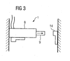
- FIG. 3 shows a further embodiment of the pyrotechnic-mechanical element 1, which is made entirely of a conductive material, for example a suitable metal in the embodiment shown.
- the pyrotechnic element 1 shown in Figure 3 a housing 8 and a switching pin 9, wherein in contrast to the embodiment shown in Figure 2, the switching pin 9 is designed to be moved out of the housing 8 in the explosion of the explosive device.
- the switching pin 9 In the operating position shown, the switching pin 9 is separated from the mating contact 14. In the extended position, however, a contact between the switching pin 9 and the mating contact 14 is provided and thus a Current flow through the pyrotechnic-mechanical element 1 allows and bridges the faulty power semiconductor module.
Landscapes
- Engineering & Computer Science (AREA)
- Power Engineering (AREA)
- Electronic Switches (AREA)
- Protection Of Static Devices (AREA)
- Semiconductor Integrated Circuits (AREA)
Applications Claiming Priority (1)
| Application Number | Priority Date | Filing Date | Title |
|---|---|---|---|
| PCT/DE2006/000344 WO2007095873A1 (de) | 2006-02-23 | 2006-02-23 | Einrichtung zum kurzschliessen von leistungshalbleitermodulen |
Publications (2)
| Publication Number | Publication Date |
|---|---|
| EP1992000A1 EP1992000A1 (de) | 2008-11-19 |
| EP1992000B1 true EP1992000B1 (de) | 2013-10-30 |
Family
ID=37057328
Family Applications (1)
| Application Number | Title | Priority Date | Filing Date |
|---|---|---|---|
| EP06706013.7A Expired - Lifetime EP1992000B1 (de) | 2006-02-23 | 2006-02-23 | Einrichtung zum kurzschliessen von leistungshalbleitermodulen |
Country Status (6)
| Country | Link |
|---|---|
| US (1) | US8164868B2 (https=) |
| EP (1) | EP1992000B1 (https=) |
| JP (1) | JP2009527877A (https=) |
| CA (1) | CA2643110C (https=) |
| DE (1) | DE112006003864A5 (https=) |
| WO (1) | WO2007095873A1 (https=) |
Cited By (1)
| Publication number | Priority date | Publication date | Assignee | Title |
|---|---|---|---|---|
| EP3417534A1 (de) * | 2016-03-11 | 2018-12-26 | Siemens Aktiengesellschaft | Anordnung mit einem modul eines stromrichters und einem schalter |
Families Citing this family (26)
| Publication number | Priority date | Publication date | Assignee | Title |
|---|---|---|---|---|
| DE102007018344B4 (de) | 2007-04-16 | 2022-08-04 | Siemens Energy Global GmbH & Co. KG | Vorrichtung zum Schutz von Umrichtermodulen |
| WO2009092621A1 (de) * | 2008-01-22 | 2009-07-30 | Siemens Aktiengesellschaft | Kurzschlussvorrichtung mit pyrotechnischer auslösung |
| DE102008059670B3 (de) * | 2008-11-26 | 2010-06-17 | Siemens Aktiengesellschaft | Vakuumschalter mit beidseitig fest verschienten Anschlussklemmen |
| US8611113B2 (en) * | 2009-01-16 | 2013-12-17 | Abb Technology Ag | Fault protection in voltage source converters with redundant switching cells via mechanical switches being closed pyrotechnically |
| FR2946455B1 (fr) | 2009-06-08 | 2011-07-01 | Areva T & D Sa | Commutateur de court-circuit a securite amelioree. |
| DE102010010669A1 (de) * | 2010-03-04 | 2011-09-08 | Siemens Aktiengesellschaft | Schalter mit beidseitig fest verschienten Anschlussklemmen |
| KR20130006622A (ko) | 2010-03-18 | 2013-01-17 | 에이비비 리써치 리미티드 | 캐스케이딩된 컨버터들에 대한 컨버터 셀, 결함 컨버터 셀을 바이패싱하기 위한 제어 시스템 및 방법 |
| WO2011154047A1 (de) * | 2010-06-11 | 2011-12-15 | Siemens Aktiengesellschaft | Umrichter mit schalterüberwachung |
| FR2971080B1 (fr) * | 2011-02-02 | 2013-03-01 | Alstom Grid Sas | Appareillage d'ampoule a vide comprenant un moyen de verrouillage |
| FR2971079B1 (fr) | 2011-02-02 | 2013-03-01 | Alstom Grid Sas | Appareillage electrique comprenant une partie mobile a dynamique amelioree |
| CN103635998B (zh) | 2011-06-21 | 2016-08-17 | Abb技术有限公司 | 具有接触机构的功率半导体壳体 |
| US9443683B2 (en) | 2012-04-24 | 2016-09-13 | Commscope Technologies Llc | RF thermal fuse |
| EP2720246B1 (en) * | 2012-10-09 | 2015-07-08 | CommScope Technologies LLC | RF thermal fuse |
| FR3010827A1 (fr) * | 2013-09-13 | 2015-03-20 | Commissariat Energie Atomique | Interrupteur destine a court circuiter une source de tension continue de puissance |
| GB2520566A (en) * | 2013-11-26 | 2015-05-27 | Dynex Semiconductor Ltd | Fail Safe Switch |
| JP6366711B2 (ja) * | 2014-06-30 | 2018-08-01 | 三菱電機株式会社 | 電力変換装置 |
| JP6109430B2 (ja) * | 2014-08-28 | 2017-04-05 | 三菱電機株式会社 | 高速投入器およびこれを備えたスイッチギヤ |
| US11239038B2 (en) * | 2015-05-18 | 2022-02-01 | Gigavac, Llc | Mechanical fuse device |
| US10566160B2 (en) | 2015-05-18 | 2020-02-18 | Gigavac, Llc | Passive triggering mechanisms for use with switching devices incorporating pyrotechnic features |
| DE102016115222B4 (de) * | 2016-06-30 | 2020-02-13 | Dehn Se + Co Kg | Kurzschließeinrichtung für den Einsatz in Nieder- und Mittelspannungsanlagen zum Sach- und Personenschutz |
| RU2686659C1 (ru) * | 2017-06-02 | 2019-04-30 | Дмитрий Валерьевич Хачатуров | Быстродействующее коммутационное устройство |
| EP3818550B1 (de) * | 2018-08-08 | 2022-12-07 | Siemens Energy Global GmbH & Co. KG | Anordnung mit einem überbrückungsschalter |
| US11443910B2 (en) | 2019-09-27 | 2022-09-13 | Gigavac, Llc | Contact levitation triggering mechanisms for use with switching devices incorporating pyrotechnic features |
| FR3103309B1 (fr) | 2019-11-19 | 2023-10-27 | Gigavac Llc | Dispositifs de commutation incorporant un disque de rupture |
| CN118696393A (zh) * | 2022-02-25 | 2024-09-24 | 株式会社大赛璐 | 电路切换装置 |
| SE2350818A1 (en) * | 2023-06-30 | 2024-12-31 | Scibreak Ab | Arrangement, system, and method for bypassing faulty submodules in an electric circuit breaker |
Family Cites Families (17)
| Publication number | Priority date | Publication date | Assignee | Title |
|---|---|---|---|---|
| US3564305A (en) * | 1965-04-05 | 1971-02-16 | Aerojet General Co | Method and apparatus for creating pulsed magnetic field in a large volume |
| GB1321381A (en) | 1971-01-20 | 1973-06-27 | Post Office | Protective circuit assemblies including explosively operated electrical switches |
| JPS5494632A (en) | 1978-01-09 | 1979-07-26 | Toshiba Corp | Converter device |
| JPS5539630U (https=) * | 1978-09-08 | 1980-03-14 | ||
| JPS5539630A (en) | 1978-09-13 | 1980-03-19 | Fujitsu Ltd | Vapor phase growth device |
| GB2153609B (en) | 1984-02-02 | 1987-12-02 | Lucas Elect Electron Syst | Surge suppressor |
| DD225540A1 (de) | 1984-07-02 | 1985-07-31 | Inst Prueffeld Elekt | Antrieb fuer elektrische schalter mit explosivstoffzuendung |
| US4939619A (en) * | 1987-01-26 | 1990-07-03 | Northern Telecom Limited | Packaged solid-state surge protector |
| GB2290854B (en) * | 1994-06-28 | 1996-07-31 | Mark Buyers | Safety module for use in a wellbore |
| WO1997041582A1 (de) * | 1996-04-27 | 1997-11-06 | Dynamit Nobel Gmbh Explosivstoff- Und Systemtechnik | Pyrotechnisches schaltelement für elektrische stromkreise |
| DE19726534A1 (de) * | 1997-06-23 | 1998-12-24 | Asea Brown Boveri | Leistungshalbleitermodul mit geschlossenen Submodulen |
| US6046514A (en) | 1997-07-25 | 2000-04-04 | 3M Innovative Properties Company | Bypass apparatus and method for series connected energy storage devices |
| DE19922674A1 (de) * | 1999-05-18 | 2000-11-23 | Goetz Coenen | Pyrotechnischer Aktuator |
| DE19955682A1 (de) | 1999-11-19 | 2001-06-13 | Abb Patent Gmbh | Strombegrenzende Einrichtung für Hochspannung |
| EP1282145A1 (de) | 2001-07-30 | 2003-02-05 | Abb Research Ltd. | Verfahren und Vorrichtung zum selbstgezündeten pyrotechnischen Kurzschliessen |
| DE10254497B3 (de) | 2002-11-22 | 2004-06-03 | Moeller Gmbh | Kurzschließer für eine Störlichtbogen-Schutzvorrichtung |
| DE10323220B4 (de) * | 2003-05-22 | 2014-07-17 | Siemens Aktiengesellschaft | Kurzschluss-Schaltung für einen Teilumrichter |
-
2006
- 2006-02-23 JP JP2008555602A patent/JP2009527877A/ja active Pending
- 2006-02-23 CA CA2643110A patent/CA2643110C/en not_active Expired - Lifetime
- 2006-02-23 DE DE112006003864T patent/DE112006003864A5/de not_active Withdrawn
- 2006-02-23 WO PCT/DE2006/000344 patent/WO2007095873A1/de not_active Ceased
- 2006-02-23 EP EP06706013.7A patent/EP1992000B1/de not_active Expired - Lifetime
- 2006-02-23 US US12/280,562 patent/US8164868B2/en active Active
Cited By (2)
| Publication number | Priority date | Publication date | Assignee | Title |
|---|---|---|---|---|
| EP3417534A1 (de) * | 2016-03-11 | 2018-12-26 | Siemens Aktiengesellschaft | Anordnung mit einem modul eines stromrichters und einem schalter |
| EP3417534B1 (de) * | 2016-03-11 | 2025-07-16 | Siemens Energy Global GmbH & Co. KG | Modularer multilevelstromrichter |
Also Published As
| Publication number | Publication date |
|---|---|
| US8164868B2 (en) | 2012-04-24 |
| US20090141416A1 (en) | 2009-06-04 |
| JP2009527877A (ja) | 2009-07-30 |
| DE112006003864A5 (de) | 2009-01-29 |
| CA2643110C (en) | 2014-09-16 |
| CA2643110A1 (en) | 2007-08-30 |
| EP1992000A1 (de) | 2008-11-19 |
| WO2007095873A1 (de) | 2007-08-30 |
Similar Documents
| Publication | Publication Date | Title |
|---|---|---|
| EP1992000B1 (de) | Einrichtung zum kurzschliessen von leistungshalbleitermodulen | |
| DE10049071B4 (de) | Sicherungsvorrichtung für einen Stromkreis insbesondere in Kraftfahrzeugen | |
| EP2483976B1 (de) | Überspannungsschutzelement | |
| DE10103336C1 (de) | Lade-/Entlade-Schutzschaltung für eine wiederaufladbare Batterie | |
| DE102016222339A1 (de) | Pyrotechnischer schalter und zwischenkreis-entladungssystem | |
| EP1458072B1 (de) | Kurzschliesseinrichtung für den Einsatz- in Nieder- und Mittelspannungsanlagen | |
| DE102014117280A1 (de) | Sicherheitsschaltgerät zum Ein- und sicheren Ausschalten eines elektrischen Verbrauchers | |
| WO1991000636A1 (de) | Insassen-sicherheitseinrichtung für fahrzeuge | |
| EP3963685A1 (de) | Blitzschutz-funkenstreckenanordnung und verfahren zum betreiben einer blitzschutz-funkenstreckenanordnung | |
| WO2009052953A1 (de) | Brennstoffzellensystem mit zumindest einer brennstoffzelle | |
| DE10313045B3 (de) | Kurzschließeinrichtung für den Einsatz in Nieder- und Mittelspannungsanlagen | |
| DE102016208420A1 (de) | Anordnung mit multifunktionalem Anschluss für Energiespeicherzellen oder Energieverbraucher | |
| DE4430284A1 (de) | Einrichtung für Kraftfahrzeuge zur unfallbedingten Trennung einer elektrischen Energiequelle von einem Bordnetz | |
| EP1079993B1 (de) | Verfahren und vorrichtung zur überprüfung eines elektrischen schaltkreises, insbesondere eines zündschaltkreises eines kraftfahrzeug-insassenschutzsystems | |
| DE102021125555A1 (de) | Sicherungsvorrichtung für Hochvoltanwendungen | |
| DE10111252A1 (de) | Anordnung zum Schutz von Vebrauchern | |
| DE102009018612A1 (de) | Auslöseelement für ein Kraftfahrzeugbordnetz | |
| DE102004019817A1 (de) | Schaltungsanordnung zum Schutz von elektrischen Verbrauchern in Kraftfahrzeugen | |
| DE102020118100B4 (de) | Sicherungselement | |
| DE10329082A1 (de) | Elektrisches Bauelement, insbesondere Laserdiodenbauelement, elektronische Schaltungsanordnung mit einer Mehrzahl von seriell zueinander verschalteten elektrischen Serienelementen und Überbrückungselement für ein elektrisches Serienelement | |
| EP1282145A1 (de) | Verfahren und Vorrichtung zum selbstgezündeten pyrotechnischen Kurzschliessen | |
| DE102007028929B3 (de) | Messfühler zum Einsatz bei einer Leistungselektronik | |
| DE20005783U1 (de) | Schaltungsanordnung zur Prüfung des Zündenergiespeichers eines Zündkreises | |
| WO2015028586A1 (de) | Sicherungselement für eine überspannungsschutzeinrichtung | |
| DE102016000504A1 (de) | Überwachungseinrichtung für wenigstens eine galvanische Zelle zum Speichern von elektrischer Energie |
Legal Events
| Date | Code | Title | Description |
|---|---|---|---|
| PUAI | Public reference made under article 153(3) epc to a published international application that has entered the european phase |
Free format text: ORIGINAL CODE: 0009012 |
|
| 17P | Request for examination filed |
Effective date: 20080731 |
|
| AK | Designated contracting states |
Kind code of ref document: A1 Designated state(s): CH DE GB LI SE |
|
| RIN1 | Information on inventor provided before grant (corrected) |
Inventor name: DORN, JOERG Inventor name: PREIDEL, AXEL Inventor name: HOLWEG, JOHANN Inventor name: DOMMASCHK, MIKE Inventor name: LANG, JOERG Inventor name: WUERFLINGER, KLAUS |
|
| DAX | Request for extension of the european patent (deleted) | ||
| RBV | Designated contracting states (corrected) |
Designated state(s): CH DE GB LI SE |
|
| 17Q | First examination report despatched |
Effective date: 20101209 |
|
| RAP1 | Party data changed (applicant data changed or rights of an application transferred) |
Owner name: SIEMENS AKTIENGESELLSCHAFT |
|
| GRAP | Despatch of communication of intention to grant a patent |
Free format text: ORIGINAL CODE: EPIDOSNIGR1 |
|
| INTG | Intention to grant announced |
Effective date: 20130603 |
|
| GRAS | Grant fee paid |
Free format text: ORIGINAL CODE: EPIDOSNIGR3 |
|
| GRAA | (expected) grant |
Free format text: ORIGINAL CODE: 0009210 |
|
| AK | Designated contracting states |
Kind code of ref document: B1 Designated state(s): CH DE GB LI SE |
|
| REG | Reference to a national code |
Ref country code: GB Ref legal event code: FG4D Free format text: NOT ENGLISH |
|
| REG | Reference to a national code |
Ref country code: CH Ref legal event code: EP Ref country code: CH Ref legal event code: NV Representative=s name: SIEMENS SCHWEIZ AG, CH |
|
| REG | Reference to a national code |
Ref country code: DE Ref legal event code: R096 Ref document number: 502006013315 Country of ref document: DE Effective date: 20131224 |
|
| REG | Reference to a national code |
Ref country code: SE Ref legal event code: TRGR |
|
| RAP2 | Party data changed (patent owner data changed or rights of a patent transferred) |
Owner name: SIEMENS AKTIENGESELLSCHAFT |
|
| REG | Reference to a national code |
Ref country code: DE Ref legal event code: R026 Ref document number: 502006013315 Country of ref document: DE |
|
| PLBI | Opposition filed |
Free format text: ORIGINAL CODE: 0009260 |
|
| 26 | Opposition filed |
Opponent name: ABB AB Effective date: 20140728 |
|
| PLAX | Notice of opposition and request to file observation + time limit sent |
Free format text: ORIGINAL CODE: EPIDOSNOBS2 |
|
| REG | Reference to a national code |
Ref country code: DE Ref legal event code: R026 Ref document number: 502006013315 Country of ref document: DE Effective date: 20140728 |
|
| PLBB | Reply of patent proprietor to notice(s) of opposition received |
Free format text: ORIGINAL CODE: EPIDOSNOBS3 |
|
| REG | Reference to a national code |
Ref country code: DE Ref legal event code: R100 Ref document number: 502006013315 Country of ref document: DE |
|
| PLCK | Communication despatched that opposition was rejected |
Free format text: ORIGINAL CODE: EPIDOSNREJ1 |
|
| PLBN | Opposition rejected |
Free format text: ORIGINAL CODE: 0009273 |
|
| STAA | Information on the status of an ep patent application or granted ep patent |
Free format text: STATUS: OPPOSITION REJECTED |
|
| 27O | Opposition rejected |
Effective date: 20160623 |
|
| REG | Reference to a national code |
Ref country code: CH Ref legal event code: PCOW Free format text: NEW ADDRESS: WERNER-VON-SIEMENS-STRASSE 1, 80333 MUENCHEN (DE) |
|
| REG | Reference to a national code |
Ref country code: DE Ref legal event code: R081 Ref document number: 502006013315 Country of ref document: DE Owner name: SIEMENS ENERGY GLOBAL GMBH & CO. KG, DE Free format text: FORMER OWNER: SIEMENS AKTIENGESELLSCHAFT, 80333 MUENCHEN, DE |
|
| REG | Reference to a national code |
Ref country code: GB Ref legal event code: 732E Free format text: REGISTERED BETWEEN 20220811 AND 20220817 |
|
| PGFP | Annual fee paid to national office [announced via postgrant information from national office to epo] |
Ref country code: DE Payment date: 20250226 Year of fee payment: 20 |
|
| PGFP | Annual fee paid to national office [announced via postgrant information from national office to epo] |
Ref country code: SE Payment date: 20250224 Year of fee payment: 20 |
|
| PGFP | Annual fee paid to national office [announced via postgrant information from national office to epo] |
Ref country code: CH Payment date: 20250301 Year of fee payment: 20 |
|
| PGFP | Annual fee paid to national office [announced via postgrant information from national office to epo] |
Ref country code: GB Payment date: 20250218 Year of fee payment: 20 |
|
| REG | Reference to a national code |
Ref country code: CH Ref legal event code: H14 Free format text: ST27 STATUS EVENT CODE: U-0-0-H10-H14 (AS PROVIDED BY THE NATIONAL OFFICE) Effective date: 20260223 Ref country code: DE Ref legal event code: R071 Ref document number: 502006013315 Country of ref document: DE |
|
| REG | Reference to a national code |
Ref country code: GB Ref legal event code: PE20 Expiry date: 20260222 |