EP1991959B1 - Auf listenmodusdaten basierende lokale bewegungskompensation - Google Patents
Auf listenmodusdaten basierende lokale bewegungskompensation Download PDFInfo
- Publication number
- EP1991959B1 EP1991959B1 EP07717552.9A EP07717552A EP1991959B1 EP 1991959 B1 EP1991959 B1 EP 1991959B1 EP 07717552 A EP07717552 A EP 07717552A EP 1991959 B1 EP1991959 B1 EP 1991959B1
- Authority
- EP
- European Patent Office
- Prior art keywords
- response
- lines
- interest
- region
- motion
- Prior art date
- Legal status (The legal status is an assumption and is not a legal conclusion. Google has not performed a legal analysis and makes no representation as to the accuracy of the status listed.)
- Not-in-force
Links
- 230000004044 response Effects 0.000 claims description 46
- 238000000034 method Methods 0.000 claims description 38
- 239000013598 vector Substances 0.000 claims description 25
- 238000012937 correction Methods 0.000 claims description 14
- 238000002059 diagnostic imaging Methods 0.000 claims description 13
- 238000013519 translation Methods 0.000 claims description 9
- 210000003484 anatomy Anatomy 0.000 claims description 3
- 230000008569 process Effects 0.000 claims description 3
- 238000007670 refining Methods 0.000 claims 1
- 238000012800 visualization Methods 0.000 description 15
- 238000003384 imaging method Methods 0.000 description 10
- 238000004422 calculation algorithm Methods 0.000 description 9
- 238000002600 positron emission tomography Methods 0.000 description 9
- 230000005855 radiation Effects 0.000 description 9
- 238000002591 computed tomography Methods 0.000 description 8
- 230000003902 lesion Effects 0.000 description 7
- 238000012545 processing Methods 0.000 description 7
- 238000001514 detection method Methods 0.000 description 6
- 238000001914 filtration Methods 0.000 description 5
- 230000036961 partial effect Effects 0.000 description 5
- 238000004458 analytical method Methods 0.000 description 4
- 230000008901 benefit Effects 0.000 description 4
- 238000003702 image correction Methods 0.000 description 4
- 210000004072 lung Anatomy 0.000 description 4
- 238000002595 magnetic resonance imaging Methods 0.000 description 4
- 241001417495 Serranidae Species 0.000 description 3
- 239000013078 crystal Substances 0.000 description 3
- 230000006870 function Effects 0.000 description 3
- 230000005251 gamma ray Effects 0.000 description 3
- 230000007246 mechanism Effects 0.000 description 3
- 238000011002 quantification Methods 0.000 description 3
- 230000029058 respiratory gaseous exchange Effects 0.000 description 3
- 230000004075 alteration Effects 0.000 description 2
- 238000013459 approach Methods 0.000 description 2
- 230000000747 cardiac effect Effects 0.000 description 2
- 230000003247 decreasing effect Effects 0.000 description 2
- 238000009795 derivation Methods 0.000 description 2
- 230000000694 effects Effects 0.000 description 2
- 238000012986 modification Methods 0.000 description 2
- 230000004048 modification Effects 0.000 description 2
- 229940121896 radiopharmaceutical Drugs 0.000 description 2
- 239000012217 radiopharmaceutical Substances 0.000 description 2
- 230000002799 radiopharmaceutical effect Effects 0.000 description 2
- 238000002603 single-photon emission computed tomography Methods 0.000 description 2
- 238000012879 PET imaging Methods 0.000 description 1
- 230000003321 amplification Effects 0.000 description 1
- 239000000872 buffer Substances 0.000 description 1
- 238000004364 calculation method Methods 0.000 description 1
- 238000004891 communication Methods 0.000 description 1
- 230000003750 conditioning effect Effects 0.000 description 1
- 125000004122 cyclic group Chemical group 0.000 description 1
- 230000003111 delayed effect Effects 0.000 description 1
- 230000001788 irregular Effects 0.000 description 1
- 230000000670 limiting effect Effects 0.000 description 1
- 239000004973 liquid crystal related substance Substances 0.000 description 1
- 208000037841 lung tumor Diseases 0.000 description 1
- 239000011159 matrix material Substances 0.000 description 1
- 238000003199 nucleic acid amplification method Methods 0.000 description 1
- 230000003287 optical effect Effects 0.000 description 1
- 230000002093 peripheral effect Effects 0.000 description 1
- 238000012805 post-processing Methods 0.000 description 1
- 238000007781 pre-processing Methods 0.000 description 1
- 238000002360 preparation method Methods 0.000 description 1
- 230000005258 radioactive decay Effects 0.000 description 1
- 230000002829 reductive effect Effects 0.000 description 1
- 230000000241 respiratory effect Effects 0.000 description 1
- 239000007787 solid Substances 0.000 description 1
- 230000002123 temporal effect Effects 0.000 description 1
- 230000036962 time dependent Effects 0.000 description 1
Images


Classifications
-
- G—PHYSICS
- G06—COMPUTING; CALCULATING OR COUNTING
- G06T—IMAGE DATA PROCESSING OR GENERATION, IN GENERAL
- G06T11/00—2D [Two Dimensional] image generation
- G06T11/003—Reconstruction from projections, e.g. tomography
- G06T11/006—Inverse problem, transformation from projection-space into object-space, e.g. transform methods, back-projection, algebraic methods
-
- A—HUMAN NECESSITIES
- A61—MEDICAL OR VETERINARY SCIENCE; HYGIENE
- A61B—DIAGNOSIS; SURGERY; IDENTIFICATION
- A61B6/00—Apparatus or devices for radiation diagnosis; Apparatus or devices for radiation diagnosis combined with radiation therapy equipment
- A61B6/02—Arrangements for diagnosis sequentially in different planes; Stereoscopic radiation diagnosis
- A61B6/03—Computed tomography [CT]
- A61B6/037—Emission tomography
-
- G—PHYSICS
- G06—COMPUTING; CALCULATING OR COUNTING
- G06T—IMAGE DATA PROCESSING OR GENERATION, IN GENERAL
- G06T2211/00—Image generation
- G06T2211/40—Computed tomography
- G06T2211/412—Dynamic
Definitions
- the following relates to medical imaging systems. It finds particular application to motion compensation in PET imaging, but is also applicable to other modalities of diagnostic imaging.
- Anatomical motion is a known problem in medical imaging (e.g., Positron Emission Tomography (PET), Single Photon Emission Computed Tomography (SPECT), Computed Tomography (CT), Magnetic Resonance Imaging (MR), etc.).
- PET Positron Emission Tomography
- SPECT Single Photon Emission Computed Tomography
- CT Computed Tomography
- MR Magnetic Resonance Imaging
- the lungs and other portions of the anatomy undergo cyclic movement with patient breathing, the cardiac cycle, and the like.
- Such movement during data acquisition results in motion-averaged (e.g., blurred) images, which tend to have low image quality and limited quantification capabilities (e.g., reduced contrast, decreased lesion detectability, worsened standardized uptake value (SUV) quantitation, etc.).
- SUV standardized uptake value
- One technique used to reduce motion artifact is to have the patient hold their breath during data acquisition. However, in some instances the acquisition time is too long for the patient to hold their breath during the entire data acquisition.
- Conventional active motion correction schemes e.g., deformation model
- deformation model can be very complex and time-consuming, and prone to errors.
- they typically require additional input about the breathing state of the patient over time, which needs to be acquired with external sensors.
- a method for correcting motion in an image reconstructed by a reconstruction system of an imaging system with raw data including lines of response (LORs) as defined in claim 1 includes estimating a characteristic feature of a region of interest within the reconstructed image from the LORs.
- the LORs associated with the region of interest are then corrected for motion with the estimated region characteristic feature.
- a motion-corrected image corresponding to the region of interest with the corrected LORs is then reconstructed.
- One advantage includes facilitating correcting for motion artifact in an image.
- Another advantage lies in using the data employed to reconstruct an image to correct for motion in that image.
- Another advantage resides in eliminating the need for physical motion detectors and complex motion correction algorithms.
- FIGURE 1 illustrates a medical imaging system 10 that includes a scanning system 12 and a console 14 that controls the scanning system 12, presents reconstructed images, and provides visualization and data/image correction tools.
- the scanning system 12 can be any type of medical imaging scanner including one or more of a Positron Emission Tomography (PET) scanner, a Single Photon Emission Computed Tomography (SPECT) scanner, a Computed Tomography (CT) scanner, a Magnetic Resonance Imaging (MR) scanner, a PET/CT scanner, etc.
- PET Positron Emission Tomography
- SPECT Single Photon Emission Computed Tomography
- CT Computed Tomography
- MR Magnetic Resonance Imaging
- PET/CT scanner a PET/CT scanner
- the scanning system 12 is a PET scanner.
- the scanning system 12 includes a plurality of radiation detector modules 16 (e.g., hundreds, thousands, etc.), each arranged around an imaging region 18.
- the modules 16 are positioned or rotated to define one or more rings (e.g., two, ten, a hundred, etc.) of radiation detectors along an axial direction that detect radiation events (e.g., gamma rays) occurring within the imaging region 18.
- the scanning system 12 also includes a support mechanism 20 for positioning a subject (e.g., a human) in the imaging region 18 before, during and/or after imaging.
- the support mechanism 20 may be linearly movable in an axial direction generally transverse to the radiation detectors 16.
- the console 14 is a microprocessor-based system (e.g., a mainframe, a workstation, a desktop, a laptop, etc.).
- the console 14 includes at least one or more processors 22, storage components 24 (e.g., volatile and non-volatile, resident and portable memory, etc.), presentation components 26 (e.g., a flat panel monitor, a liquid crystal display (LCD), a cathode ray tube (CRT) monitor etc.), input devices 28 (e.g., a mouse, a keyboard, a keypad, a roller ball, a digital pen, a microphone, a touch screen, tape drive, disk drive, etc.), input drives 30 (e.g., DVD, CD, magnetic disk, optical disk, tape, etc.), wire and/or wireless communication components 32 (e.g., Ethernet, USB, serial, parallel, FireWire, etc.), as well as various other computer related components.
- storage components 24 e.g., volatile and non-volatile, resident and portable memory
- the console 14 is used to plan patient procedures (e.g., provide for selecting imaging protocol(s), suitably setting imaging parameters, etc.), commence scanning with the scanning system 12, present reconstructed images, and provide various visualization and data/image correction capabilities, as well as other functions such terminating procedures, transferring data, positioning the support mechanism 20, etc.
- suitable visualization capabilities include but are not limited to, forming three dimensional volumes from a two dimensional data sets, defining primitives (e.g., regions and/or volumes of interest), measuring various image quality statistics, superimposing images obtained through different modalities, removing anatomy and/or a defined region/volume of interest from within an image, etc.
- these visualization capabilities are leveraged to facilitate removing motion artifact from various regions (e.g., one or more regions or volumes of interest, etc.) in an image through one or more motion estimation/correction algorithms executed by the one or more processors 22.
- These algorithms use the data (e.g., list mode data) employed to reconstruct images to correct the motion within the reconstructed images.
- a radiopharmaceutical is administered to the subject, and the subject is suitably positioned within the imaging region 18.
- the radiopharmaceutical undergoes radioactive decay, which results in an emission of a positron.
- the positron interacts with one or more nearby electrons and annihilates, which produces two oppositely directed gamma rays having energies of about 511 keV each.
- the two oppositely directed gamma rays strike opposing detector modules 16 concurrently at substantially the same time. Since positions not originating equidistant from a pair of detectors travel different distances, there is a time offset between coincident events.
- a typical detector module 16 includes one or more scintillation crystals (not shown). Each scintillation crystal produces a scintillation of light when struck by a radiation event such as a gamma ray produced from positron annihilation. The light produced by each crystal is received by one or more photodetectors (not shown) such as photomultiplier tubes. Each of the photodetectors converts the light into a representative electrical signal. Solid state detectors which generate the electrical signals directly in response to receiving radiation and other types of detection systems are also contemplated. The resulting electrical signal from the one or more photodetectors are conveyed and processed by one or more processing components 34. Suitable processing by the processing components 34 includes signal amplification, filtering, and/or conditioning. The processed electrical signals are then conveyed to a converter 36, which digitizes and time stamps the signals. Buffers and/or other storage medium (not shown) can be used to facilitate pre-processing and digitizing the signals.
- the data is then conveyed to a coincident detector 38 that identifies pairs of substantially simultaneous coincident gamma ray detections, which correspond to electron-positron annihilation event pairs.
- This processing can include, for example, energy filtering (e.g., discarding radiation detection events outside of a selected energy filtering window disposed about 511 keV) and/or coincidence filtering (e.g., discarding radiation detection event pairs temporally separated from each other by greater than a selected time filtering interval or more than two events within a common window, random coincidence identification using a delayed windowing technique, etc.).
- a line of response (LOR) processor 40 processes the spatial information for each pair of events to identify a spatial LOR that connects gamma ray detections in each pair. Since the two gamma rays emitted by a positron-electron annihilation event are oppositely spatially directed, the electron-positron annihilation event is known to have occurred somewhere on the LOR. In time-of-flight (TOF) PET, the processor 40 analyzes a difference between the detection times of the pair of gamma rays to determine a segment along the LOR along which the annihilation event occurred.
- TOF time-of-flight
- the spatial LOR and/or the pairs of coincident events are conveyed to an artifact corrector 42 (which is described in greater detail below) that is associated with a simplified reconstruction system 43 (which can be part of the artifact corrector 42 as depicted here or external to the artifact corrector 42 as depicted in FIGURE 2 below) that at least facilitates motion correcting the LORs, a reconstruction system 44, a storage component 46, and/or a visualization system 48.
- the reconstruction system 44 reconstructs one or more images from this data using any suitable reconstruction algorithm. Examples of suitable algorithms include, but are not limited to, filtered backprojection and/or iterative backprojection with or without correction. Because the motion correction might artifact areas of the image outside the region of interest, in one embodiment an image combiner 50 replaces the ROI of a non-corrected image with the ROI from the motion corrected image.
- the resulting reconstructed images and/or raw data can be conveyed to the console 14 and stored in the one or more of the storage components 24 and/or presented to the user via the one or more presentation components 26. Additionally or alternatively, the resulting reconstructed images can be conveyed to the storage component 46. In this instance, the console 14 can obtain the reconstructed images and/or raw data from the storage component 46. Additionally or alternatively, the reconstructed images and/or raw data can be conveyed to the visualization system 48 from the console 14, the reconstruction system 44, and/or the storage component 46. Both the console 14 and the visualization system 48 can send data and/or images to one or more peripheral devices 52, including a filmer, a printer, a plotter, a facsimile, an email address, a computer, a network, etc.
- peripheral devices 52 including a filmer, a printer, a plotter, a facsimile, an email address, a computer, a network, etc.
- the console 14 provides various visualization and data/image correction capabilities.
- the clinician can employ the visualization and data/image correction capabilities to view and/or correct for image artifacts (e.g., motion artifact).
- image artifacts e.g., motion artifact
- Such capabilities can be part of the system software and/or applications stored in the storage components 24 and executed by the processors 22.
- the visualization system 48 can be used to facilitate real-time and/or post-processing artifact correction.
- the visualization system 48 may be a dedicated processing system with specialized hardware (not shown) such as graphics engines, graphics accelerators, larger quantities of memory, higher powered processors, high resolution monitors, etc. and/or specialized software applications that facilitated complex and time intensive image processing algorithms.
- the console 14 and the visualization system 48 are combined into a single unit to provide scanner control as well as advanced image processing capabilities.
- a first technique (presented below in FIGURE 2 ) uses a simplified Siddon based algorithm, and another technique (presented below in FIGURE 6 ) uses a vector space approach.
- the LOR processor 40 conveys the remaining LORs to a grouper 52 of the artifact corrector 42.
- the grouper 52 divides the LORs into groups that span about 100 milliseconds, for example.
- the time span can be fixed and the number of LORs per group can vary.
- the number of LORs can be fixed to about 10000, for example, and the time span can vary.
- both the number and time span can be thresholded or otherwise both be allowed to vary, within constraints.
- a filter 54 filters out the LORs that do not intersect a user or automatically defined volume of interest / region of interest (VOI/ROI) 56.
- VOI/ROI volume of interest / region of interest
- a characteristic processor 58 determines a characteristic feature such as the center of mass or other center function of the LORs of each group.
- a controller 60 of the characteristic processor 58 accesses the simplified reconstruction system 43 to reconstruct each group of LORs into a partial image.
- FIGURE 3 illustrates a graphical example of the VOI/ROI 56 and a plurality of exemplary intermediate images 62 derived from the VOI/ROI 56 by the simplified reconstruction system 43. Ten intermediate images 62 are illustrated; however, in other embodiments, more intermediate images can be generated.
- each LOR with each voxel is not calculated. Instead, the voxel values inside the VOI/ROI 56 are increased by one for each voxel that is intersected by the LOR for each of the intermediate images 62.
- FIGURE 4 illustrates a LOR 64 intersects voxels 66, 68, 70, 72, 74 and 76 within the VOI/ROI 56.
- the value of each of the voxels 66-76 is increased by one.
- This simplified back projection is computationally efficient as the number of required divisions and multiplications is minimal.
- the time for generating a sufficient number of intermediate images 62 typically is in the order of a few seconds.
- the partial images are stored in a storage component 78.
- a center of mass (COM) generator 80 computes a center of mass or other characteristic feature of each partial image stored in the storage component 78.
- the locally constrained back projection described above may have a significant background from events outside the VOI/ROI 56.
- the data is thresholded such that only voxels with values above about 50% (or other percentage deemed suitable by the clinician) of the maximum ROI/VOI value are considered in the calculation of the center of mass.
- a variance processor 82 determines a translational offset or other deviation between a center of mass or other characteristic feature of a current group of LORs and a pre-selected center of mass or other characteristic feature stored in a memory 84.
- the pre-selected center can be set as the center of mass of a first group processed, a motion artifacted image, or the like or can be operator selected.
- the deviation of each center of mass is stored in a vector, an array, a string, a matrix, and the like.
- FIGURE 5 graphically illustrates information about the position of the center of mass for each time partial image. The overall center of mass deviations for the full time range is used to calculate a time dependent translation vector 86.
- a LOR shifter 88 corrects the list mode data for motion by shifting each LOR or each group of LORs in the original data set by an amount given by the deviation (e.g., the translation vector 86) to get a motion corrected list mode dataset. This is done at the full timing resolution of the list mode dataset, unlike conventional gating techniques in which the data is still averaged or smeared over the duration of each time frame. This correction can also be integrated as part of a real time image reconstruction. It is assumed that deformation of the tissue inside the ROI/VOI can be neglected, so that the motion of the center of mass reflects the motion of the tissue inside the ROI/VOI. This assumption is reasonable for small VOIs. Although described based on translation, other connections are also contemplated, such as rotational, elasticity, and the like.
- the shifted or otherwise deviation corrected LORs along with translated or non-translated LORs from outside the VOI/ROI are then reconstructed by the reconstruction system 44. Because the LORs have all been shifted to the target center of mass, the reconstructed image of the region of interest is motion corrected. In one instance, the resulting corrected image and an uncorrected image are presented by the presentation component 26 of the console 14 in different display windows. In another instance, the data is motion corrected and reconstructed in substantially real time as it is read out of the scanner. As each additional group of LORs becomes part of the displayed image, the display image builds progressively sharper. In yet another instance, a portion of the corrected image is spliced into the corresponding region of a larger uncorrected image. The various images, combinations of images and/or derivations thereof are presented by the presentation component 26 of the console 14. In yet another instance, the motion corrected image is provided to the storage component 46 and/or the visualization system 48.
- the characteristic processor 56 alternatively determines a center of mass for the LORs with a vector analysis component 96.
- the LOR processor 40 provides the LORs to the artifact corrector 42.
- the grouper 52 of the artifact corrector 42 divides the LORs into one or more groups.
- the filter 54 filters out the LORs outside of the VOI/ROI 56 and, in the case of TOF PET, the LORs that intersect the volume of interest, but whose segment identifying the possible location of the annihilation event falls outside of VOI/ROI 56.
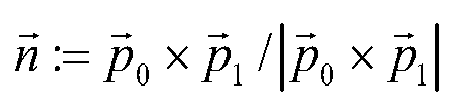
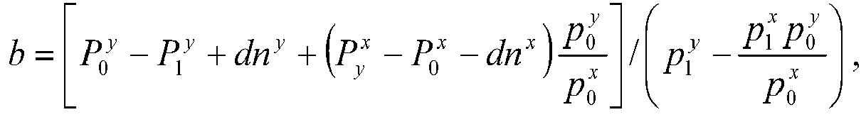
- each LOR in the list mode emission data is defined by a point P x on a LOR and a unit vector p ⁇ x pointing in the direction of the LOR.
- FIGURE 7 illustrates two such LORs in which a first LOR 98 is associated with a point P 98 and a unit vector p ⁇ 98 pointing in the direction of the LOR 98, and a second LOR 100 is associated with point P 100 and a unit vector p ⁇ 100 pointing in the direction of the LOR 100.
- the point C represents the center point of the shortest line segment 102 connecting the LORs 98 and 100.
- the vector analysis component 96 uses this information to determine the center of mass of this point cloud, which is an estimate of the center of mass of the activity distribution in the specified ROI/VOI.
- the above technique can be improved by eliminating outliers of the point cloud.
- FIGURE 8 illustrates exemplary results for simulated list mode data of a moving sphere.
- results are graphically presented in a plot 104 illustrating position at a first axis 106 and time at a second axis 108.
- the numbers of events specified at 110 were used to determine the position of the sphere over time directly from the list mode data.
- the variance processor 82 determines a suitable translation function or other deviation between the current group of LORs and the pre-selected center of mass stored in the memory 84.
- the LOR shifter 88 adjusts the LORs with the offset or other deviation.
- the adjusted or otherwise deviation corrected LORs along with translated or non-translated LORs from outside the VOI/ROI are then reconstructed by the reconstruction system 44.
- the reconstructed image of the region of interest is motion corrected.
- the motion corrected image is then provided to the console 14, the storage component 46, and/or the visualization component 48.
- the clinician is interested in quantitative values (e.g., for a specific lung lesion).
- the clinician manually defines a region or volume of interest by contouring (via the one or the input devices 28) a geometric primitive on the image presented by the one or more presentation components 26.
- the clinician can draw a primitive that encapsulates a substantial portion of a subject lesion.
- the primitive may be a square, a rectangle, a circle, an ellipse, a free hand shape, a sphere, a cube, etc., and/or any other two or three dimensional shapes that the console 14 and/or the visualization system 46 provides for region or volume of interest definition.
- an algorithm can be utilized to automatically define one or more such regions or volumes of interest. For example, based on a range of values (e.g., defined by the clinician or predefined) that correspond to the grey scale values of the lesion, the executing software can threshold image pixel (or voxel) values and trace a region that includes data within the range. This may result in automatic contouring of a "hot spot," or region of relatively higher emission of radiation, in the image. Similarly, the shape of this primitive may be based on known geometric shapes or irregular in shape. Where multiple imaging modalities are used, the region or volume of interest can be defined on an image generated with data from one modality and this image can be registered to an image generated with data from a different modality. For example, in instances where PET/CT are combined, the clinician can define the region of interest in the CT image, and the CT image can subsequently be registered to the PET image.
- a range of values e.g., defined by the clinician or predefined
- the executing software can threshold image pixel (or vo
- time-of-flight (TOF) information is available, it can be exploited to improve motion estimation.
- the number of time steps, i.e. the temporal resolution of motion estimation could be adjustable via the graphical user interface (GUI).
- the number of events used for the estimation of the centre of mass could be adjustable via the GUI.
- an algorithm can determine the optimal setting for these parameters.
- the foregoing techniques can be used for various applications including quantification of lung lesions or the staging of lung tumors or other applications in which localized objects are quantified (e.g., size and absolute activity concentration) under respiratory, cardiac or patient motion.
Landscapes
- Engineering & Computer Science (AREA)
- Physics & Mathematics (AREA)
- Life Sciences & Earth Sciences (AREA)
- Health & Medical Sciences (AREA)
- Theoretical Computer Science (AREA)
- General Physics & Mathematics (AREA)
- Medical Informatics (AREA)
- Nuclear Medicine, Radiotherapy & Molecular Imaging (AREA)
- Biomedical Technology (AREA)
- Mathematical Physics (AREA)
- Mathematical Optimization (AREA)
- Biophysics (AREA)
- High Energy & Nuclear Physics (AREA)
- Mathematical Analysis (AREA)
- Algebra (AREA)
- Optics & Photonics (AREA)
- Pathology (AREA)
- Radiology & Medical Imaging (AREA)
- Pure & Applied Mathematics (AREA)
- Heart & Thoracic Surgery (AREA)
- Molecular Biology (AREA)
- Surgery (AREA)
- Animal Behavior & Ethology (AREA)
- General Health & Medical Sciences (AREA)
- Public Health (AREA)
- Veterinary Medicine (AREA)
- Nuclear Medicine (AREA)
- Apparatus For Radiation Diagnosis (AREA)
- Magnetic Resonance Imaging Apparatus (AREA)
Claims (21)
- Verfahren zum Korrigieren von Bewegung in einem aus Rohdaten rekonstruierten Bild einschließlich Verbindungslinien (engl. lines of response, LOR), umfassend:das Schätzen eines charakteristischen Merkmals einer interessierenden Region innerhalb des rekonstruierten Bilds anhand der Verbindungslinien, wobei für Verbindungslinienpaare (98, 100) Vektoren berechnet werden (102), die Mittelpunkte der kürzesten Liniensegmente darstellen, welche ein jeweiliges Paar von Verbindungslinien in den Rohdaten verbinden, wodurch eine Punktverteilung gebildet wird, wobei das charakteristische Merkmal als ein Massenzentrum der Verteilung in der interessierenden Region berechnet wird;das Korrigieren der zu der interessierenden Region gehörigen Verbindungslinien bezüglich der Bewegung mit dem geschätzten für die Region charakteristischen Merkmal, wobei die Verbindungslinien in den Originaldaten entsprechend der Bewegung des Massenzentrums verschoben werden; unddas Rekonstruieren eines bezüglich der Bewegung korrigierten Bilds entsprechend der interessierenden Region mit den korrigierten Verbindungslinien.
- Verfahren nach Anspruch 1, wobei die Rohdaten Listenmodusdaten sind.
- Verfahren nach Anspruch 1, wobei die interessierende Region kleiner als ein Sichtfeld ist und auf der interessierenden Anatomie lokalisiert ist.
- Verfahren nach Anspruch 1, weiterhin umfassend:das Ersetzen der unkorrigierten interessierenden Region durch das Bild mit der bezüglich der Bewegung korrigierten interessierenden Region.
- Verfahren nach Anspruch 1, weiterhin umfassend das gleichzeitige Darstellen der bezüglich der Bewegung korrigierten interessierenden Region und des unkorrigierten Bilds in separaten Anzeigen.
- Verfahren nach Anspruch 1, wobei der Vektor eine Sammlung von Punkten für eine gegebene Anzahl von aufeinanderfolgenden Verbindungslinienpaaren umfasst.
- Verfahren nach Anspruch 1, wobei der Vektor berechnet wird als eine Funktion von

P 0 undP 1 Punkte auf einem Verbindungslinienpaar sind undp 0 undp 1 die Einheitsrichtungsvektoren für diese Verbindungslinien sind, d eine Länge des kürzesten Liniensegments ist, das die Verbindungslinien verbindet und definiert ist durch
- Verfahren nach Anspruch 1, weiterhin umfassend das Verfeinern des Ergebnisses, indem Daten außerhalb der interessierenden Region ignoriert werden.
- Verfahren nach Anspruch 1, wobei das Korrigieren der Verbindungslinien Folgendes umfasst:das zeitliche Aufteilen der Verbindungslinien in Gruppen;das Ermitteln eines Orts des charakteristischen Merkmals in jeder Gruppe anhand von Daten in jeder Gruppe;das Ermitteln einer Abweichung zwischen dem Ort des geschätzten charakteristischen Merkmals in jeder Gruppe und dem geschätzten charakteristischen Merkmal;das Anpassen der Verbindungslinien in Übereinstimmung mit den ermittelten Abweichungen.
- Verfahren nach Anspruch 9, wobei der Schritt des Anpassens Folgendes umfasst:das Verschieben der Verbindungslinien in Übereinstimmung mit den ermittelten Abweichungen, um die charakteristischen Merkmale der Gruppen auszurichten.
- Verfahren zum Korrigieren von Bewegung in einem anhand von Rohdaten rekonstruierten Bild einschließlich Verbindungslinien, wobei das Verfahren Folgendes umfasst:das Schätzen eines charakteristischen Merkmals einer interessierenden Region innerhalb des rekonstruierten Bilds anhand der Verbindungslinien, wobei das charakteristische Merkmal ein Massenzentrum ist;das Korrigieren der zu der interessierenden Region gehörigen Verbindungslinien bezüglich der Bewegung mit dem für die Region geschätzten charakteristischen Merkmal; unddas Rekonstruieren eines bezüglich der Bewegung korrigierten Bilds entsprechend der interessierenden Region mit den korrigierten Verbindungslinien,wobei das Verfahren weiterhin in Verbindung mit den Schritten des Schätzens des Massenzentrums und des Korrigierens der Rohdaten Folgendes umfasst:das Erzeugen einer Vielzahl von Zwischenbildern der interessierenden Region (62) anhand von Segmenten der Rohdaten für eine Anzahl von kurzen Zeitrahmen;das Anpassen, für jedes der Vielzahl von Zwischenbildern der interessierenden Regionen (62), eines Voxelwerts für ein oder mehrere Voxel (66-76), die sich innerhalb der interessierenden Region (56) befinden und die eine entsprechende Verbindungslinie (64) kreuzen, indem der Voxelwert um eins erhöht wird;das Berechnen des Massenzentrums für jedes der Zwischenbilder der interessierenden Regionen (62);das Berechnen einer Differenz zwischen jedem Massenzentrum und einem ausgewählten Massenzentrum;das Berechnen eines Bewegungskorrekturtranslationsvektor (86) basierend auf den Differenzen; unddas Korrigieren der Rohdaten bezüglich der Bewegung durch Verschieben der Verbindungslinien in den Originaldaten um einen durch den Bewegungskorrekturtranslationsvektor gegebenen Betrag.
- Verfahren nach Anspruch 11, weiterhin umfassend:das Entfernen von Voxeln mit Werten von weniger als einem vorgegebenen Prozentsatz einer maximalen interessierenden Region vor der Schätzung des Massenzentrums, um den Einfluss von Koinzidenzen außerhalb der interessierenden Region zu verringern (56).
- Verfahren nach Anspruch 11, weiterhin Folgendes umfassend, um die Bewegungskorrektur zu verbessern:das Verwenden von Time-of-Flight-Informationen zur Vereinfachung der Bewegungsschätzung, wobei die Time-of-Flight-Informationen verwendet werden, um Verbindungslinien zu entfernen, die die interessierende Region kreuzen, aber deren Segment angibt, dass ein möglicher Ort eines Annihilationsereignisses außerhalb der interessierenden Region liegt.
- Computerimplementiertes Programm zum Ausführen des Verfahrens nach Anspruch 1 oder Anspruch 11.
- Computerlesbares Medium, auf dem Anweisungen zum Implementieren des Verfahrens nach Anspruch 1 oder Anspruch 11 gespeichert sind.
- Medizinisches Bildgebungssystem (10), das Bewegung in einem rekonstruierten Bild mit Daten korrigiert, die zum Rekonstruieren des Bilds verwendet werden, umfassend:eine Vielzahl von Detektoren (16), die Elektronen-Positronen-Annihilationsereignisse detektieren;einen Koinzidenzdetektor (38), der Paare von im Wesentlichen gleichzeitigen Koinzidenzereignissen innerhalb der Elektronen-Positronen-Annihilationsereignisse identifiziert;einen Verbindungslinienprozessor (40), der die Ereignisse verarbeitet und Verbindungslinien identifiziert, die Ereignisse innerhalb jedes koinzidenten Ereignispaares verbinden; undeinen oder mehrere Prozessoren (22, 42), die programmiert sind zum:Schätzen eines charakteristischen Merkmals einer interessierenden Region anhand der Verbindungslinien, wobei für Verbindungslinienpaare Vektoren berechnet werden, die Mittelpunkte der kürzesten Liniensegmente darstellen, welche ein jeweiliges Paar von Verbindungslinien in den Rohdaten verbinden, wodurch eine Punktverteilung gebildet wird, wobei das charakteristische Merkmal als ein Massenzentrum der Verteilung in der interessierenden Region berechnet wird;Korrigieren der der interessierenden Region entsprechenden Verbindungslinien bezüglich der Bewegung, wobei die Verbindungslinien in den Originaldaten entsprechend der Bewegung des Massenzentrums verschoben werden; undRekonstruieren eines bezüglich der Bewegung korrigierten Bilds entsprechend der interessierenden Region mit den korrigierten Verbindungslinien.
- Medizinisches Bildgebungssystem (10) nach Anspruch 16, wobei die Verbindungslinien Listenmodusdaten sind.
- Medizinisches Bildgebungssystem (10) nach Anspruch 16, wobei die interessierende Region auf weniger als ein Sichtfeld des medizinischen Bildgebungssystems (10) lokalisiert ist.
- Medizinisches Bildgebungssystem (10) nach Anspruch 16, weiterhin umfassend:das Darstellen von Komponenten (26), die mindestens eines von Folgendem darstellen:das bezüglich der Bewegung korrigierte Bild,gleichzeitige Anzeigen des bezüglich der Bewegung korrigierten Bilds und eines unkorrigierten Bilds, undein unkorrigiertes Bild mit der bezüglich der Bewegung korrigierten interessierenden Region anstelle der entsprechenden interessierenden Region des unkorrigierten Bilds.
- Medizinisches Bildgebungssystem (10) nach Anspruch 16, wobei der eine oder mehrere Prozessoren weiterhin programmiert sind zum:Gruppieren der Verbindungslinien in zeitlich zusammenhängende Gruppen;Schätzen eines Orts des charakteristischen Merkmals in jeder Gruppe anhand der Verbindungslinien in jeder Gruppe;Verschieben der Verbindungslinien derartig, dass die Orte des charakteristischen Merkmals in jeder Gruppe ausgerichtet werden, um die bezüglich der Bewegung korrigierten Verbindungslinien für die Rekonstruktion zu erzeugen.
- Medizinisches Bildgebungssystem (10), das Bewegung in einem rekonstruierten Bild mit Daten korrigiert, die zum Rekonstruieren des Bilds verwendet werden, umfassend:eine Vielzahl von Detektoren (16), die Elektronen-Positronen-Annihilationsereignisse detektieren;einen Koinzidenzdetektor (38), der Paare von im Wesentlichen gleichzeitigen Koinzidenzereignissen innerhalb der Elektronen-Positronen-Annihilationsereignisse identifiziert;einen Verbindungslinienprozessor (40), der die Ereignisse verarbeitet und Verbindungslinien identifiziert, die Ereignisse innerhalb jedes koinzidenten Ereignispaares verbinden; undeinen oder mehrere Prozessoren (22, 42), die programmiert sind zum:Schätzen eines charakteristischen Merkmals einer interessierenden Region innerhalb des rekonstruierten Bilds anhand der Verbindungslinien, wobei das charakteristische Merkmal ein Massenzentrum ist;Korrigieren der der interessierenden Region entsprechenden Verbindungslinien bezüglich der Bewegung mit dem für die Region geschätzten charakteristischen Merkmal; undRekonstruieren eines bezüglich der Bewegung korrigierten Bilds entsprechend der interessierenden Region mit den korrigierten Verbindungslinien,wobei der eine oder mehrere Prozessoren (22, 42) weiterhin dafür programmiert sind, in Verbindung mit den Schritten des Schätzens des Massenzentrums und des Korrigierens der Verbindungslinien Folgendes durchzuführen:das Erzeugen einer Vielzahl von Zwischenbildern der interessierenden Region (62) anhand von Segmenten der Rohdaten für eine Anzahl von kurzen Zeitrahmen;das Anpassen, für jedes der Vielzahl von Zwischenbildern der interessierenden Regionen (62), eines Voxelwerts für ein oder mehrere Voxel (66-76), die sich innerhalb der interessierenden Region (56) befinden und die eine entsprechende Verbindungslinie (64) kreuzen, indem der Voxelwert um eins erhöht wird;das Berechnen des Massenzentrums für jedes der Zwischenbilder der interessierenden Regionen (62);das Berechnen einer Differenz zwischen jedem Massenzentrum und einem ausgewählten Massenzentrum;das Berechnen eines Bewegungskorrekturtranslationsvektor (86) basierend auf den Differenzen; unddas Korrigieren der Rohdaten bezüglich der Bewegung durch Verschieben der Verbindungslinien in den Originaldaten um einen durch den Bewegungskorrekturtranslationsvektor gegebenen Betrag.
Applications Claiming Priority (2)
| Application Number | Priority Date | Filing Date | Title |
|---|---|---|---|
| US77746906P | 2006-02-28 | 2006-02-28 | |
| PCT/US2007/061597 WO2007100955A2 (en) | 2006-02-28 | 2007-02-05 | Local motion compensation based on list mode data |
Publications (2)
| Publication Number | Publication Date |
|---|---|
| EP1991959A2 EP1991959A2 (de) | 2008-11-19 |
| EP1991959B1 true EP1991959B1 (de) | 2017-08-30 |
Family
ID=38459705
Family Applications (1)
| Application Number | Title | Priority Date | Filing Date |
|---|---|---|---|
| EP07717552.9A Not-in-force EP1991959B1 (de) | 2006-02-28 | 2007-02-05 | Auf listenmodusdaten basierende lokale bewegungskompensation |
Country Status (5)
| Country | Link |
|---|---|
| US (1) | US8144962B2 (de) |
| EP (1) | EP1991959B1 (de) |
| JP (1) | JP5254810B2 (de) |
| CN (1) | CN101454801B (de) |
| WO (1) | WO2007100955A2 (de) |
Families Citing this family (62)
| Publication number | Priority date | Publication date | Assignee | Title |
|---|---|---|---|---|
| US8588367B2 (en) * | 2007-02-07 | 2013-11-19 | Koninklijke Philips N.V. | Motion compensation in quantitative data analysis and therapy |
| JP2010528312A (ja) * | 2007-05-30 | 2010-08-19 | コーニンクレッカ フィリップス エレクトロニクス エヌ ヴィ | Pet局所断層撮影 |
| WO2009040690A2 (en) * | 2007-09-24 | 2009-04-02 | Koninklijke Philips Electronics N.V. | Preclinical time of flight pet imaging |
| US8017915B2 (en) | 2008-03-14 | 2011-09-13 | Reflexion Medical, Inc. | Method and apparatus for emission guided radiation therapy |
| US8472683B2 (en) * | 2008-05-09 | 2013-06-25 | General Electric Company | Motion correction in tomographic images |
| US8515148B2 (en) | 2008-05-28 | 2013-08-20 | Koninklijke Philips N.V. | Geometrical transformations preserving list-mode format |
| RU2517586C2 (ru) * | 2008-06-13 | 2014-05-27 | Конинклейке Филипс Электроникс Н.В. | Обратное реконструирование данных для оптимальной временной выработки импульсов счета в радиологической физиологической визуализации в режиме списка |
| EP2291827B1 (de) | 2008-06-18 | 2012-11-14 | Koninklijke Philips Electronics N.V. | Radiologische bildgebung mit lokaler bewegungsüberwachung, -korrektur und -beurteilung |
| EP2163201A1 (de) * | 2008-09-15 | 2010-03-17 | Westfälische Wilhelms-Universität Münster | Atmungs- und Herzgating auf Listenmodusbasis bei Positronen-Emissions-Tomographie |
| JP5523791B2 (ja) * | 2008-10-27 | 2014-06-18 | 株式会社東芝 | X線診断装置および画像処理装置 |
| JP5764069B2 (ja) * | 2009-01-19 | 2015-08-12 | コーニンクレッカ フィリップス エヌ ヴェ | リストモードpet撮像における領域再構成及び定量的評価 |
| EP2399238B1 (de) | 2009-02-17 | 2015-06-17 | Koninklijke Philips N.V. | Funktionelle bildgebung |
| WO2011033455A1 (en) | 2009-09-18 | 2011-03-24 | Koninklijke Philips Electronics N.V. | System and method for determining a property of blur in a blurred image |
| US8466419B2 (en) * | 2009-10-01 | 2013-06-18 | Kabushiki Kaisha Toshiba | System and method for enhanced sampling via helical scanning and list-mode reconstruction in positron emission tomography |
| JP6243121B2 (ja) * | 2009-12-10 | 2017-12-06 | コーニンクレッカ フィリップス エヌ ヴェKoninklijke Philips N.V. | 飛行時間情報を用いて画像化スキャンにおける動き検出及び補正をする方法と装置 |
| US9111381B2 (en) * | 2010-01-27 | 2015-08-18 | Koninklijke Philips N.V. | Shift-varying line projection using graphics hardware |
| WO2012037151A2 (en) * | 2010-09-13 | 2012-03-22 | University Of Southern California | Efficient mapping of tissue properties from unregistered data with low signal-to-noise ratio |
| US8761467B2 (en) * | 2010-10-04 | 2014-06-24 | General Electric Company | Method and apparatus for assessing motion correction |
| US8811695B2 (en) | 2010-12-14 | 2014-08-19 | General Electric Company | Methods, apparatus and articles of manufacture to adaptively reconstruct medical diagnostic images |
| EP2661735B1 (de) * | 2011-01-05 | 2017-02-22 | Koninklijke Philips N.V. | Verfahren und vorrichtung zur erkennung und korrektur von bewegung bei pet-daten im list-modus mit einem gegateten signal |
| JP6210972B2 (ja) | 2011-03-31 | 2017-10-11 | リフレクション メディカル, インコーポレイテッド | 放射誘導型放射線療法における使用のためのシステムおよび方法 |
| US9761020B2 (en) | 2011-05-12 | 2017-09-12 | Koninklijke Philips N.V. | List mode dynamic image reconstruction |
| US8421021B2 (en) * | 2011-06-21 | 2013-04-16 | General Electric Company | Motion correction of SPECT images |
| CN102324089B (zh) * | 2011-07-13 | 2013-04-03 | 南方医科大学 | 基于广义熵与mr先验的pet图像最大后验重建方法 |
| JP5846209B2 (ja) | 2011-09-15 | 2016-01-20 | 株式会社島津製作所 | 医療用データ処理装置およびそれを備えた放射線断層撮影装置 |
| CN103126701B (zh) * | 2011-11-30 | 2016-04-27 | 株式会社东芝 | 正电子发射计算机断层摄影装置和图像处理装置 |
| JP6178416B2 (ja) * | 2012-08-10 | 2017-08-09 | コーニンクレッカ フィリップス エヌ ヴェKoninklijke Philips N.V. | 連続的なベッド移動を用いた分散型リストモード飛行時間再構成のための仮想フレーム |
| DE102012216292B4 (de) * | 2012-09-13 | 2021-02-18 | Siemens Healthcare Gmbh | Magnetresonanzbaueinheit, eine Magnetresonanzvorrichtung mit der Magnetresonanzbaueinheit sowie ein Verfahren zu einem Bestimmen einer Bewegung eines Patienten während einer Magnetresonanzuntersuchung |
| KR20140042461A (ko) | 2012-09-28 | 2014-04-07 | 삼성전자주식회사 | 영상을 생성하는 방법 및 장치 |
| CA2906208C (en) * | 2013-03-15 | 2022-06-21 | Synaptive Medical (Barbados) Inc. | System and method for magnetic resonance image acquisition |
| KR101604812B1 (ko) * | 2014-01-15 | 2016-03-18 | 삼성전자주식회사 | 의료 영상 처리 장치 및 그에 따른 의료 영상 처리 방법 |
| CN103942763A (zh) * | 2014-05-03 | 2014-07-23 | 南方医科大学 | 一种基于mr信息引导的体素水平pet图像部分容积校正方法 |
| DE102014219376A1 (de) * | 2014-09-25 | 2016-03-31 | Siemens Aktiengesellschaft | Verfahren zu einer Erfassung eines hochaufgelösten Magnetresonanzbilddatensatzes zumindest eines begrenzten Körperbereichs mit zumindest einer anatomischen Struktur eines Patienten |
| US9606245B1 (en) | 2015-03-24 | 2017-03-28 | The Research Foundation For The State University Of New York | Autonomous gamma, X-ray, and particle detector |
| JP6850482B2 (ja) | 2015-06-10 | 2021-03-31 | リフレクション メディカル, インコーポレイテッド | 高帯域幅バイナリマルチリーフコリメータ設計 |
| CN107133549B (zh) * | 2016-02-29 | 2020-11-24 | 上海联影医疗科技有限公司 | Ect运动门控信号获取方法及ect图像重建方法 |
| EP3426345B1 (de) | 2016-03-09 | 2021-06-23 | RefleXion Medical, Inc. | Fluenzkartenerzeugungsverfahren für strahlentherapie |
| CN106097384B (zh) * | 2016-05-30 | 2018-12-18 | 江苏赛诺格兰医疗科技有限公司 | 一种确定门控信号的方法和装置 |
| CN106548473B (zh) * | 2016-11-07 | 2019-03-08 | 赛诺联合医疗科技(北京)有限公司 | 一种构建相位图像的方法及装置 |
| CN110248604B (zh) | 2016-11-15 | 2023-07-21 | 反射医疗公司 | 放射治疗患者平台 |
| WO2018093849A1 (en) | 2016-11-15 | 2018-05-24 | Reflexion Medical, Inc. | Methods for radiation delivery in emission-guided radiotherapy |
| EP3988017A1 (de) | 2016-11-15 | 2022-04-27 | RefleXion Medical, Inc. | System zur emissionsgeführten abgabe von energiereichen photonen |
| WO2018099772A1 (en) * | 2016-11-29 | 2018-06-07 | Koninklijke Philips N.V. | Interactive targeted ultrafast reconstruction in emission and transmission tomography |
| KR101946576B1 (ko) * | 2016-12-23 | 2019-02-11 | 삼성전자주식회사 | 의료 영상 장치 및 의료 영상 처리 방법 |
| US10307116B2 (en) | 2017-02-22 | 2019-06-04 | Uih America, Inc. | System and method for detecting organ motion |
| EP3602499A1 (de) * | 2017-03-24 | 2020-02-05 | Koninklijke Philips N.V. | Verfahren für datengesteuerte respiratorische bewegungsschätzung |
| WO2018183748A1 (en) | 2017-03-30 | 2018-10-04 | Reflexion Medical, Inc. | Radiation therapy systems and methods with tumor tracking |
| EP3630286A4 (de) | 2017-05-30 | 2021-03-03 | RefleXion Medical, Inc. | Verfahren zur bildgeführten strahlentherapie in echtzeit |
| CN110869086A (zh) | 2017-06-22 | 2020-03-06 | 反射医疗公司 | 生物自适应放射疗法的系统和方法 |
| EP4342521A3 (de) | 2017-07-11 | 2024-05-08 | RefleXion Medical Inc. | Verfahren zur pet-detektor-nachglühverwaltung |
| CN117761751A (zh) | 2017-07-26 | 2024-03-26 | 反射医疗公司 | 放射治疗的图形表示 |
| JP7315961B2 (ja) | 2017-08-09 | 2023-07-27 | リフレクション メディカル, インコーポレイテッド | 放出誘導放射線療法における異常検出のためのシステムおよび方法 |
| US10993689B2 (en) * | 2017-08-31 | 2021-05-04 | General Electric Company | Method and system for motion assessment and correction in digital breast tomosynthesis |
| WO2019099551A1 (en) | 2017-11-14 | 2019-05-23 | Reflexion Medical, Inc. | Systems and methods for patient monitoring for radiotherapy |
| US11151726B2 (en) * | 2018-01-10 | 2021-10-19 | Canon Medical Systems Corporation | Medical image processing apparatus, X-ray diagnostic apparatus, and medical image processing method |
| JP7409672B2 (ja) | 2018-02-13 | 2024-01-09 | リフレクション メディカル, インコーポレイテッド | ビームステーション治療計画および放射線送達方法 |
| CN108876730B (zh) * | 2018-05-24 | 2022-03-04 | 东软医疗系统股份有限公司 | 校正运动伪影的方法、装置及设备和存储介质 |
| US11426131B2 (en) * | 2018-12-17 | 2022-08-30 | Siemens Medical Solutions Usa, Inc. | Automated motion correction in PET imaging |
| WO2020150505A1 (en) | 2019-01-16 | 2020-07-23 | Reflexion Medical, Inc. | Methods for setup corrections in radiation therapy |
| US11179128B2 (en) * | 2019-12-31 | 2021-11-23 | GE Precision Healthcare LLC | Methods and systems for motion detection in positron emission tomography |
| US11494955B2 (en) * | 2020-06-10 | 2022-11-08 | Siemens Medical Solutions Usa, Inc. | Data driven reconstruction in emission tomography |
| KR20240116526A (ko) * | 2021-12-06 | 2024-07-29 | 치룬 고 | 의료 영상의 움직임 검출 및 교정을 위한 방법, 시스템 및 컴퓨터 판독 가능 매체 |
Family Cites Families (5)
| Publication number | Priority date | Publication date | Assignee | Title |
|---|---|---|---|---|
| WO1997005574A1 (en) * | 1995-07-27 | 1997-02-13 | Imperial Cancer Research Technology Limited | Raw data segmentation and analysis in image tomography |
| US6292683B1 (en) * | 1999-05-18 | 2001-09-18 | General Electric Company | Method and apparatus for tracking motion in MR images |
| US6980683B2 (en) | 2000-08-28 | 2005-12-27 | Cti Pet Systems, Inc. | On-line correction of patient motion in three-dimensional positron emission tomography |
| WO2005020801A2 (en) * | 2003-09-02 | 2005-03-10 | Ludwig Institute Of Cancer Research | Data driven motion correction for nuclear imaging |
| US7574249B2 (en) * | 2005-02-08 | 2009-08-11 | General Electric Company | Device-less gating of physiological movement for improved image detection |
-
2007
- 2007-02-05 CN CN2007800070638A patent/CN101454801B/zh not_active Expired - Fee Related
- 2007-02-05 WO PCT/US2007/061597 patent/WO2007100955A2/en active Application Filing
- 2007-02-05 US US12/279,996 patent/US8144962B2/en active Active
- 2007-02-05 EP EP07717552.9A patent/EP1991959B1/de not_active Not-in-force
- 2007-02-05 JP JP2008557440A patent/JP5254810B2/ja not_active Expired - Fee Related
Non-Patent Citations (1)
| Title |
|---|
| None * |
Also Published As
| Publication number | Publication date |
|---|---|
| CN101454801B (zh) | 2012-12-05 |
| JP5254810B2 (ja) | 2013-08-07 |
| EP1991959A2 (de) | 2008-11-19 |
| US8144962B2 (en) | 2012-03-27 |
| CN101454801A (zh) | 2009-06-10 |
| US20100166274A1 (en) | 2010-07-01 |
| WO2007100955A8 (en) | 2009-04-02 |
| WO2007100955A2 (en) | 2007-09-07 |
| JP2009528139A (ja) | 2009-08-06 |
| WO2007100955A3 (en) | 2008-08-07 |
Similar Documents
| Publication | Publication Date | Title |
|---|---|---|
| EP1991959B1 (de) | Auf listenmodusdaten basierende lokale bewegungskompensation | |
| US8098916B2 (en) | System and method for image-based attenuation correction of PET/SPECT images | |
| US8351671B2 (en) | Motion correction in nuclear imaging | |
| US9495771B2 (en) | Systems and methods for motion correction in positron emission tomography imaging | |
| US8600132B2 (en) | Method and apparatus for motion correcting medical images | |
| US7507968B2 (en) | Systems and methods for correcting a positron emission tomography emission image | |
| RU2471204C2 (ru) | Локальная позитронная эмиссионная томография | |
| CN107111867B (zh) | 多模态成像系统及方法 | |
| Yanagawa et al. | Adaptive statistical iterative reconstruction technique for pulmonary CT: image quality of the cadaveric lung on standard-and reduced-dose CT | |
| US9747701B2 (en) | Systems and methods for emission tomography quantitation | |
| US9872664B1 (en) | Methods and systems for scatter correction in positron emission tomography | |
| US20120078089A1 (en) | Method and apparatus for generating medical images | |
| US8532357B2 (en) | Method and apparatus for reducing image artifacts | |
| US20110148928A1 (en) | System and method to correct motion in gated-pet images using non-rigid registration | |
| US8415630B2 (en) | Apparatus and methods for determining a boundary of an object for positron emission tomography scatter correction | |
| US20040086199A1 (en) | Methods and apparatus for determining component alignment | |
| US20100284598A1 (en) | Image registration alignment metric | |
| US20190133542A1 (en) | Systems and methods for data-driven respiratory gating in positron emission tomography | |
| CN113116370A (zh) | 用于正电子发射断层摄影中的运动检测的方法和系统 | |
| US10852449B2 (en) | System and method for self-time alignment calibration for a positron emission tomography system | |
| EP3229689A1 (de) | Berechnung einer ausser-fov aktivität anhand von erhebungsdaten und früheren patientendaten in der positronenemissionstomografie | |
| US7853314B2 (en) | Methods and apparatus for improving image quality | |
| US10993103B2 (en) | Using time-of-flight to detect and correct misalignment in PET/CT imaging | |
| EP2715671A1 (de) | Schnelle berechnung der empfindlichkeitsmatrix bei iterativen algorithmen | |
| EP3566208A1 (de) | Verwendung der flugzeit zur detektion und korrektur der fehlausrichtung in der pet/ct-bildgebung |
Legal Events
| Date | Code | Title | Description |
|---|---|---|---|
| PUAI | Public reference made under article 153(3) epc to a published international application that has entered the european phase |
Free format text: ORIGINAL CODE: 0009012 |
|
| AK | Designated contracting states |
Kind code of ref document: A2 Designated state(s): AT BE BG CH CY CZ DE DK EE ES FI FR GB GR HU IE IS IT LI LT LU LV MC NL PL PT RO SE SI SK TR |
|
| AX | Request for extension of the european patent |
Extension state: AL BA HR MK RS |
|
| 17P | Request for examination filed |
Effective date: 20090209 |
|
| RBV | Designated contracting states (corrected) |
Designated state(s): AT BE BG CH CY CZ DE DK EE ES FI FR GB GR HU IE IS IT LI LT LU LV MC NL PL PT RO SE SI SK TR |
|
| RAP1 | Party data changed (applicant data changed or rights of an application transferred) |
Owner name: KONINKLIJKE PHILIPS ELECTRONICS N.V. Owner name: PHILIPS INTELLECTUAL PROPERTY & STANDARDS GMBH |
|
| 17Q | First examination report despatched |
Effective date: 20120123 |
|
| DAX | Request for extension of the european patent (deleted) | ||
| RAP1 | Party data changed (applicant data changed or rights of an application transferred) |
Owner name: KONINKLIJKE PHILIPS N.V. Owner name: PHILIPS INTELLECTUAL PROPERTY & STANDARDS GMBH |
|
| GRAP | Despatch of communication of intention to grant a patent |
Free format text: ORIGINAL CODE: EPIDOSNIGR1 |
|
| INTG | Intention to grant announced |
Effective date: 20170324 |
|
| RIN1 | Information on inventor provided before grant (corrected) |
Inventor name: BRINKS, RALPH Inventor name: BUSCH, MARC Inventor name: MEYER, CARSTEN |
|
| GRAS | Grant fee paid |
Free format text: ORIGINAL CODE: EPIDOSNIGR3 |
|
| GRAA | (expected) grant |
Free format text: ORIGINAL CODE: 0009210 |
|
| AK | Designated contracting states |
Kind code of ref document: B1 Designated state(s): AT BE BG CH CY CZ DE DK EE ES FI FR GB GR HU IE IS IT LI LT LU LV MC NL PL PT RO SE SI SK TR |
|
| REG | Reference to a national code |
Ref country code: GB Ref legal event code: FG4D |
|
| REG | Reference to a national code |
Ref country code: CH Ref legal event code: EP |
|
| REG | Reference to a national code |
Ref country code: AT Ref legal event code: REF Ref document number: 924255 Country of ref document: AT Kind code of ref document: T Effective date: 20170915 |
|
| REG | Reference to a national code |
Ref country code: IE Ref legal event code: FG4D |
|
| REG | Reference to a national code |
Ref country code: DE Ref legal event code: R096 Ref document number: 602007052175 Country of ref document: DE |
|
| REG | Reference to a national code |
Ref country code: NL Ref legal event code: MP Effective date: 20170830 |
|
| REG | Reference to a national code |
Ref country code: LT Ref legal event code: MG4D |
|
| REG | Reference to a national code |
Ref country code: AT Ref legal event code: MK05 Ref document number: 924255 Country of ref document: AT Kind code of ref document: T Effective date: 20170830 |
|
| PG25 | Lapsed in a contracting state [announced via postgrant information from national office to epo] |
Ref country code: LT Free format text: LAPSE BECAUSE OF FAILURE TO SUBMIT A TRANSLATION OF THE DESCRIPTION OR TO PAY THE FEE WITHIN THE PRESCRIBED TIME-LIMIT Effective date: 20170830 Ref country code: SE Free format text: LAPSE BECAUSE OF FAILURE TO SUBMIT A TRANSLATION OF THE DESCRIPTION OR TO PAY THE FEE WITHIN THE PRESCRIBED TIME-LIMIT Effective date: 20170830 Ref country code: FI Free format text: LAPSE BECAUSE OF FAILURE TO SUBMIT A TRANSLATION OF THE DESCRIPTION OR TO PAY THE FEE WITHIN THE PRESCRIBED TIME-LIMIT Effective date: 20170830 Ref country code: AT Free format text: LAPSE BECAUSE OF FAILURE TO SUBMIT A TRANSLATION OF THE DESCRIPTION OR TO PAY THE FEE WITHIN THE PRESCRIBED TIME-LIMIT Effective date: 20170830 |
|
| REG | Reference to a national code |
Ref country code: FR Ref legal event code: PLFP Year of fee payment: 12 |
|
| PG25 | Lapsed in a contracting state [announced via postgrant information from national office to epo] |
Ref country code: ES Free format text: LAPSE BECAUSE OF FAILURE TO SUBMIT A TRANSLATION OF THE DESCRIPTION OR TO PAY THE FEE WITHIN THE PRESCRIBED TIME-LIMIT Effective date: 20170830 Ref country code: BG Free format text: LAPSE BECAUSE OF FAILURE TO SUBMIT A TRANSLATION OF THE DESCRIPTION OR TO PAY THE FEE WITHIN THE PRESCRIBED TIME-LIMIT Effective date: 20171130 Ref country code: LV Free format text: LAPSE BECAUSE OF FAILURE TO SUBMIT A TRANSLATION OF THE DESCRIPTION OR TO PAY THE FEE WITHIN THE PRESCRIBED TIME-LIMIT Effective date: 20170830 Ref country code: IS Free format text: LAPSE BECAUSE OF FAILURE TO SUBMIT A TRANSLATION OF THE DESCRIPTION OR TO PAY THE FEE WITHIN THE PRESCRIBED TIME-LIMIT Effective date: 20171230 Ref country code: GR Free format text: LAPSE BECAUSE OF FAILURE TO SUBMIT A TRANSLATION OF THE DESCRIPTION OR TO PAY THE FEE WITHIN THE PRESCRIBED TIME-LIMIT Effective date: 20171201 |
|
| REG | Reference to a national code |
Ref country code: DE Ref legal event code: R081 Ref document number: 602007052175 Country of ref document: DE Owner name: PHILIPS GMBH, DE Free format text: FORMER OWNER: PHILIPS INTELLECTUAL PROPERTY STANDARDS GMBH, 20099 HAMBURG, DE Ref country code: DE Ref legal event code: R081 Ref document number: 602007052175 Country of ref document: DE Owner name: PHILIPS GMBH, DE Free format text: FORMER OWNER: PHILIPS INTELLECTUAL PROPERTY & STANDARDS GMBH, 20099 HAMBURG, DE |
|
| PG25 | Lapsed in a contracting state [announced via postgrant information from national office to epo] |
Ref country code: NL Free format text: LAPSE BECAUSE OF FAILURE TO SUBMIT A TRANSLATION OF THE DESCRIPTION OR TO PAY THE FEE WITHIN THE PRESCRIBED TIME-LIMIT Effective date: 20170830 |
|
| PG25 | Lapsed in a contracting state [announced via postgrant information from national office to epo] |
Ref country code: RO Free format text: LAPSE BECAUSE OF FAILURE TO SUBMIT A TRANSLATION OF THE DESCRIPTION OR TO PAY THE FEE WITHIN THE PRESCRIBED TIME-LIMIT Effective date: 20170830 Ref country code: PL Free format text: LAPSE BECAUSE OF FAILURE TO SUBMIT A TRANSLATION OF THE DESCRIPTION OR TO PAY THE FEE WITHIN THE PRESCRIBED TIME-LIMIT Effective date: 20170830 Ref country code: DK Free format text: LAPSE BECAUSE OF FAILURE TO SUBMIT A TRANSLATION OF THE DESCRIPTION OR TO PAY THE FEE WITHIN THE PRESCRIBED TIME-LIMIT Effective date: 20170830 Ref country code: CZ Free format text: LAPSE BECAUSE OF FAILURE TO SUBMIT A TRANSLATION OF THE DESCRIPTION OR TO PAY THE FEE WITHIN THE PRESCRIBED TIME-LIMIT Effective date: 20170830 |
|
| PG25 | Lapsed in a contracting state [announced via postgrant information from national office to epo] |
Ref country code: SK Free format text: LAPSE BECAUSE OF FAILURE TO SUBMIT A TRANSLATION OF THE DESCRIPTION OR TO PAY THE FEE WITHIN THE PRESCRIBED TIME-LIMIT Effective date: 20170830 Ref country code: EE Free format text: LAPSE BECAUSE OF FAILURE TO SUBMIT A TRANSLATION OF THE DESCRIPTION OR TO PAY THE FEE WITHIN THE PRESCRIBED TIME-LIMIT Effective date: 20170830 Ref country code: IT Free format text: LAPSE BECAUSE OF FAILURE TO SUBMIT A TRANSLATION OF THE DESCRIPTION OR TO PAY THE FEE WITHIN THE PRESCRIBED TIME-LIMIT Effective date: 20170830 |
|
| REG | Reference to a national code |
Ref country code: DE Ref legal event code: R097 Ref document number: 602007052175 Country of ref document: DE |
|
| PLBE | No opposition filed within time limit |
Free format text: ORIGINAL CODE: 0009261 |
|
| STAA | Information on the status of an ep patent application or granted ep patent |
Free format text: STATUS: NO OPPOSITION FILED WITHIN TIME LIMIT |
|
| 26N | No opposition filed |
Effective date: 20180531 |
|
| PG25 | Lapsed in a contracting state [announced via postgrant information from national office to epo] |
Ref country code: SI Free format text: LAPSE BECAUSE OF FAILURE TO SUBMIT A TRANSLATION OF THE DESCRIPTION OR TO PAY THE FEE WITHIN THE PRESCRIBED TIME-LIMIT Effective date: 20170830 |
|
| REG | Reference to a national code |
Ref country code: CH Ref legal event code: PL |
|
| PG25 | Lapsed in a contracting state [announced via postgrant information from national office to epo] |
Ref country code: MC Free format text: LAPSE BECAUSE OF FAILURE TO SUBMIT A TRANSLATION OF THE DESCRIPTION OR TO PAY THE FEE WITHIN THE PRESCRIBED TIME-LIMIT Effective date: 20170830 |
|
| GBPC | Gb: european patent ceased through non-payment of renewal fee |
Effective date: 20180205 |
|
| REG | Reference to a national code |
Ref country code: IE Ref legal event code: MM4A |
|
| REG | Reference to a national code |
Ref country code: BE Ref legal event code: MM Effective date: 20180228 |
|
| PG25 | Lapsed in a contracting state [announced via postgrant information from national office to epo] |
Ref country code: LU Free format text: LAPSE BECAUSE OF NON-PAYMENT OF DUE FEES Effective date: 20180205 Ref country code: LI Free format text: LAPSE BECAUSE OF NON-PAYMENT OF DUE FEES Effective date: 20180228 Ref country code: CH Free format text: LAPSE BECAUSE OF NON-PAYMENT OF DUE FEES Effective date: 20180228 |
|
| PG25 | Lapsed in a contracting state [announced via postgrant information from national office to epo] |
Ref country code: IE Free format text: LAPSE BECAUSE OF NON-PAYMENT OF DUE FEES Effective date: 20180205 |
|
| PG25 | Lapsed in a contracting state [announced via postgrant information from national office to epo] |
Ref country code: BE Free format text: LAPSE BECAUSE OF NON-PAYMENT OF DUE FEES Effective date: 20180228 Ref country code: GB Free format text: LAPSE BECAUSE OF NON-PAYMENT OF DUE FEES Effective date: 20180205 |
|
| PGFP | Annual fee paid to national office [announced via postgrant information from national office to epo] |
Ref country code: FR Payment date: 20190227 Year of fee payment: 13 |
|
| PGFP | Annual fee paid to national office [announced via postgrant information from national office to epo] |
Ref country code: DE Payment date: 20190430 Year of fee payment: 13 |
|
| PG25 | Lapsed in a contracting state [announced via postgrant information from national office to epo] |
Ref country code: TR Free format text: LAPSE BECAUSE OF FAILURE TO SUBMIT A TRANSLATION OF THE DESCRIPTION OR TO PAY THE FEE WITHIN THE PRESCRIBED TIME-LIMIT Effective date: 20170830 |
|
| PG25 | Lapsed in a contracting state [announced via postgrant information from national office to epo] |
Ref country code: PT Free format text: LAPSE BECAUSE OF FAILURE TO SUBMIT A TRANSLATION OF THE DESCRIPTION OR TO PAY THE FEE WITHIN THE PRESCRIBED TIME-LIMIT Effective date: 20170830 Ref country code: HU Free format text: LAPSE BECAUSE OF FAILURE TO SUBMIT A TRANSLATION OF THE DESCRIPTION OR TO PAY THE FEE WITHIN THE PRESCRIBED TIME-LIMIT; INVALID AB INITIO Effective date: 20070205 |
|
| PG25 | Lapsed in a contracting state [announced via postgrant information from national office to epo] |
Ref country code: CY Free format text: LAPSE BECAUSE OF FAILURE TO SUBMIT A TRANSLATION OF THE DESCRIPTION OR TO PAY THE FEE WITHIN THE PRESCRIBED TIME-LIMIT Effective date: 20170830 |
|
| REG | Reference to a national code |
Ref country code: DE Ref legal event code: R119 Ref document number: 602007052175 Country of ref document: DE |
|
| PG25 | Lapsed in a contracting state [announced via postgrant information from national office to epo] |
Ref country code: DE Free format text: LAPSE BECAUSE OF NON-PAYMENT OF DUE FEES Effective date: 20200901 Ref country code: FR Free format text: LAPSE BECAUSE OF NON-PAYMENT OF DUE FEES Effective date: 20200229 |