EP1990788B1 - Vehicle path determining method and vehicle course determining device - Google Patents
Vehicle path determining method and vehicle course determining device Download PDFInfo
- Publication number
- EP1990788B1 EP1990788B1 EP07715118A EP07715118A EP1990788B1 EP 1990788 B1 EP1990788 B1 EP 1990788B1 EP 07715118 A EP07715118 A EP 07715118A EP 07715118 A EP07715118 A EP 07715118A EP 1990788 B1 EP1990788 B1 EP 1990788B1
- Authority
- EP
- European Patent Office
- Prior art keywords
- vehicle
- path
- predetermined value
- value
- evaluation
- Prior art date
- Legal status (The legal status is an assumption and is not a legal conclusion. Google has not performed a legal analysis and makes no representation as to the accuracy of the status listed.)
- Expired - Fee Related
Links
- 238000000034 method Methods 0.000 title claims description 92
- 238000011156 evaluation Methods 0.000 claims description 124
- 230000007423 decrease Effects 0.000 claims description 4
- 230000008859 change Effects 0.000 claims description 3
- 230000008569 process Effects 0.000 description 51
- 238000004364 calculation method Methods 0.000 description 15
- 238000010586 diagram Methods 0.000 description 12
- 230000009471 action Effects 0.000 description 9
- 230000001133 acceleration Effects 0.000 description 8
- 230000006870 function Effects 0.000 description 6
- 238000001514 detection method Methods 0.000 description 5
- 230000001419 dependent effect Effects 0.000 description 4
- 230000035939 shock Effects 0.000 description 3
- 230000003044 adaptive effect Effects 0.000 description 2
- 238000012854 evaluation process Methods 0.000 description 2
- 230000001010 compromised effect Effects 0.000 description 1
- 230000003111 delayed effect Effects 0.000 description 1
- 238000011161 development Methods 0.000 description 1
- 230000018109 developmental process Effects 0.000 description 1
- 230000000694 effects Effects 0.000 description 1
- 239000000446 fuel Substances 0.000 description 1
- 238000012986 modification Methods 0.000 description 1
- 230000004048 modification Effects 0.000 description 1
- 238000012545 processing Methods 0.000 description 1
- 238000006467 substitution reaction Methods 0.000 description 1
- 239000013598 vector Substances 0.000 description 1
Images


Classifications
-
- B—PERFORMING OPERATIONS; TRANSPORTING
- B60—VEHICLES IN GENERAL
- B60W—CONJOINT CONTROL OF VEHICLE SUB-UNITS OF DIFFERENT TYPE OR DIFFERENT FUNCTION; CONTROL SYSTEMS SPECIALLY ADAPTED FOR HYBRID VEHICLES; ROAD VEHICLE DRIVE CONTROL SYSTEMS FOR PURPOSES NOT RELATED TO THE CONTROL OF A PARTICULAR SUB-UNIT
- B60W30/00—Purposes of road vehicle drive control systems not related to the control of a particular sub-unit, e.g. of systems using conjoint control of vehicle sub-units, or advanced driver assistance systems for ensuring comfort, stability and safety or drive control systems for propelling or retarding the vehicle
- B60W30/10—Path keeping
-
- B—PERFORMING OPERATIONS; TRANSPORTING
- B60—VEHICLES IN GENERAL
- B60W—CONJOINT CONTROL OF VEHICLE SUB-UNITS OF DIFFERENT TYPE OR DIFFERENT FUNCTION; CONTROL SYSTEMS SPECIALLY ADAPTED FOR HYBRID VEHICLES; ROAD VEHICLE DRIVE CONTROL SYSTEMS FOR PURPOSES NOT RELATED TO THE CONTROL OF A PARTICULAR SUB-UNIT
- B60W40/00—Estimation or calculation of non-directly measurable driving parameters for road vehicle drive control systems not related to the control of a particular sub unit, e.g. by using mathematical models
- B60W40/02—Estimation or calculation of non-directly measurable driving parameters for road vehicle drive control systems not related to the control of a particular sub unit, e.g. by using mathematical models related to ambient conditions
-
- G—PHYSICS
- G05—CONTROLLING; REGULATING
- G05D—SYSTEMS FOR CONTROLLING OR REGULATING NON-ELECTRIC VARIABLES
- G05D1/00—Control of position, course or altitude of land, water, air, or space vehicles, e.g. automatic pilot
- G05D1/02—Control of position or course in two dimensions
- G05D1/021—Control of position or course in two dimensions specially adapted to land vehicles
- G05D1/0212—Control of position or course in two dimensions specially adapted to land vehicles with means for defining a desired trajectory
- G05D1/0214—Control of position or course in two dimensions specially adapted to land vehicles with means for defining a desired trajectory in accordance with safety or protection criteria, e.g. avoiding hazardous areas
-
- G—PHYSICS
- G05—CONTROLLING; REGULATING
- G05D—SYSTEMS FOR CONTROLLING OR REGULATING NON-ELECTRIC VARIABLES
- G05D1/00—Control of position, course or altitude of land, water, air, or space vehicles, e.g. automatic pilot
- G05D1/02—Control of position or course in two dimensions
- G05D1/021—Control of position or course in two dimensions specially adapted to land vehicles
- G05D1/0212—Control of position or course in two dimensions specially adapted to land vehicles with means for defining a desired trajectory
- G05D1/0217—Control of position or course in two dimensions specially adapted to land vehicles with means for defining a desired trajectory in accordance with energy consumption, time reduction or distance reduction criteria
-
- G—PHYSICS
- G08—SIGNALLING
- G08G—TRAFFIC CONTROL SYSTEMS
- G08G1/00—Traffic control systems for road vehicles
- G08G1/16—Anti-collision systems
- G08G1/166—Anti-collision systems for active traffic, e.g. moving vehicles, pedestrians, bikes
-
- G—PHYSICS
- G08—SIGNALLING
- G08G—TRAFFIC CONTROL SYSTEMS
- G08G1/00—Traffic control systems for road vehicles
- G08G1/16—Anti-collision systems
- G08G1/167—Driving aids for lane monitoring, lane changing, e.g. blind spot detection
Definitions
- the present invention relates to own-vehicle-path determining methods and own-vehicle-path determining apparatuses which determine one own-vehicle-path candidate as an optimal drivable path from plural predicted own-vehicle-path candidates, and more particularly, to own-vehicle-path determining methods and own-vehicle-path determining apparatuses suitable for automatic driving of an own vehicle.
- Document US 6,169 495 discloses a vehicle traffic control system which is designed such that no conflicts at road intersections are caused. For this, matrices are generated, which are based on the present position, speed and destination of each vehicle, based on which vectors indicating possible courses for each vehicle are generated.
- Document WO 00/40929 discloses a multi-dimensional route optimizer, which refers in particular to an aircraft flight path.
- a lateral path optimizer and a vertical path optimizer are provided, wherein a lateral path is determined by searching for a path among nodes that minimizes a cost function, whereas the vertical path is determined by reference to aircraft parameters and the wind speed.
- Document WO 03/025507 also discloses a route planer for an airplane, which uses a recursive algorithm to determine a lateral path and an adaptive algorithm to determine a vertical path.
- Nonpatent Literature 1 the path found through the prediction by the technique described in Nonpatent Literature 1 is often unreasonable because this technique focuses on predicting a path which is safe for all the objects constituting the system. For example, on a highway, if a vehicle is running ahead of an own vehicle at a lower speed on the same driving lane, a driver of the own vehicle may think he/she can pass. However, since it is safer to simply follow the other slower vehicle, a path following the other vehicle is selected as a safe path based on the prediction. Then, sometimes the arrival to the destination is delayed. In brief, though such techniques may realize an extremely high driving safety, its driving efficiency can be extremely low.
- the present invention is made in view of the above, and an object of the present invention is to provide an own-vehicle-path determining method and an own-vehicle-path determining apparatus which can determine an appropriate own-vehicle path from plural predicted own-vehicle-path candidates.
- the own-vehicle-path determining method and the own-vehicle-path determining apparatus calculate the first evaluation value and the second evaluation value of the own vehicle relative to each of the plural predicted own-vehicle-path candidates, select own-vehicle-path candidates with a high first evaluation value and a high second evaluation value as appropriate own-vehicle-path candidates from the plural own-vehicle-path candidates, and select any one of the appropriate own-vehicle-path candidates as an own-vehicle path, whereby an appropriate own-vehicle path can be determined through an appropriate setting of the first evaluation value and the second evaluation value.
- the own-vehicle-path determining method and the own-vehicle-path determining apparatus calculate the first evaluation value and the second evaluation value of the own vehicle relative to each of the plural predicted own-vehicle-path candidates, and select an own-vehicle-path candidate having a maximum second evaluation value among those having a high first evaluation value from the plural own-vehicle-path candidates as a drivable path of the own vehicle, whereby an appropriate own-vehicle path can be determined through an appropriate setting of the first evaluation value and the second evaluation value.
- the own-vehicle-path determining method and the own-vehicle-path determining apparatus calculate the first evaluation value which indicates an evaluation of the safety of the own vehicle relative to each of the plural predicted own-vehicle-path candidates and the second evaluation value which indicates an evaluation of driving efficiency of each of the own-vehicle-path candidates, and select an own-vehicle-path candidate having a maximum second evaluation value among those having a first evaluation value higher than a set predetermined value as a drivable path of the own vehicle from the plural own-vehicle-path candidates, whereby an own-vehicle path can be determined through an appropriate setting of the predetermined value, which is used for accepting the first evaluation value, depending on a situation while safety and driving efficiency are harmonized in a realistic manner. For example, selection of a passing path is accepted so as to realize early arrival at the destination even though the safety is slightly compromised within a range satisfying the safety standard.
- FIG. 1 is a schematic block diagram of a functional configuration of an own-vehicle-path determining apparatus according to one embodiment of the present invention.
- the own-vehicle-path determining apparatus is mounted on an own vehicle, which is an automobile running on a road, to detect obstacles such as other vehicles present within a predetermined surrounding range of the own vehicle and determine an own-vehicle path for automatically driving the own vehicle in consideration of detected obstacles.
- An own-vehicle-path determining apparatus 1 includes an input unit 2 which inputs various information from outside, a sensor unit 3 which detects a position and an internal condition of an object present within a predetermined range, a track generator 4 which, based on a result of detection by the sensor unit 3, generates a track representing a possible positional change of an object over time in a time-space configured with time and space, a predicting unit 5 which makes a probabilistic prediction of a path of an object such as the own vehicle and the other vehicle using a track generated by the track generator 4, an interference evaluator/action selector 6 which calculates possibility of interference between the own vehicle and the other vehicle based on the result of prediction of the object in the predicting unit 5 to select an optimal drivable path as the own-vehicle path, a storage unit 7 which stores information such as a track in the time-space generated by the track generator 4 and a result of prediction by the predicting unit 5, a predetermined value input unit 8 which serves to input and set
- the input unit 2 has a function of receiving an input of information such as various types of setting information for the prediction of paths of moving objects such as the own vehicle and the other vehicle.
- the input unit 2 is implemented with a remote control, a keyboard (including touchscreen-type devices which allow input from a display), a pointing device (such as a mouse and a track pad), for example.
- a microphone can be arranged as the input unit 2 so that information can be input via voice.
- the sensor unit 3 is implemented with a millimeter-wave radar, a laser radar, an image sensor, and the like.
- the sensor unit 3 includes variety of sensors such as a speed sensor, an acceleration sensor, a rudder angle sensor, and an angular velocity sensor, and is able to detect moving condition of the own vehicle.
- An internal condition of the object detected by the sensor unit 3 has significance in prediction of objects, and preferably is a physical value such as speed, acceleration, angular velocity, and angular acceleration of the object.
- the physical value, such as speed and angular velocity of the moving object such as an own vehicle can be zero (which means that the object is in a halt) naturally.
- the track generator 4 includes an operation selector 41 which selects an operation for a moving object such as the own vehicle and the other vehicle from plural operations, an object operator 42 which performs an operation selected by the operation selector 41 for a predetermined time period, and a determining unit 43 which determines whether the position and the internal condition of the moving object such as the own vehicle and the other vehicle satisfy a predetermined condition after the operation by the object operator 42.
- the predicting unit 5 performs a probabilistic predicting calculation of the path of the object using the track output from the track generator 4 for each moving object such as the own vehicle and the other vehicle.
- the interference evaluator/action selector 6 includes an own-vehicle-path safety evaluator 61 which calculates a safety evaluation value (first evaluation value) indicating an evaluation of the safety of the own vehicle by calculating a possibility of interference such as collision between the other vehicle and each of the plural own-vehicle-path candidates predicted by the predicting unit 5, an own-vehicle-path efficiency evaluator 62 which calculates an efficiency evaluation value (second evaluation value which is an evaluation value indicating how fast the vehicle can reach the destination, for example) which indicates an evaluation of driving efficiency of each of the plural own-vehicle-path candidates predicted by the predicting unit 5, and a setting-based most-efficient path selector 63 which selects, as a drivable path of the own vehicle, an own-vehicle-path candidate whose safety evaluation value satisfies safety condition by exceeding a predetermined set value and which has a highest efficient evaluation value among the plural own-vehicle-path candidates.
- a safety evaluation value first evaluation
- the predetermined value input unit 8 allows setting and input of a predetermined value to be employed in the process by the setting-based most-efficient path selector 63 for determining whether the safety evaluation value of each own-vehicle-path candidate is acceptable in terms of safety.
- a predetermined value for example, an accelerator pedal, a brake pedal, and a mode-selecting switch of driving modes (which switches between, for example, a sport mode and a luxury mode) can be adopted as the predetermined value input unit 8.
- the storage unit 7 stores operations for the selection by the operation selector 41 of the track generator 4, in addition to the track generated by the track generator 4 and the result of prediction by the predicting unit 5. Further, the storage unit 7 includes a predetermined value storage unit 71 which stores a predetermined value input and set by the predetermined value input unit 8, and supplies the stored predetermined value to the setting-based most-efficient path selector 63 for the determination process.
- the storage unit 7 is implemented with a Read Only Memory (ROM) which previously stores therein a program that starts up a predetermined Operation System (OS), an object-path predicting program, an own-vehicle path determining program, and the like according to the embodiment, and a Random Access Memory (RAM) which stores therein operation parameters, data, and the like for each process.
- the storage unit 7 can be implemented with an interface and a computer-readable recording medium corresponding to the interface in such a manner that the computer-readable recording medium can be mounted in the interface provided in the own-vehicle-path determining apparatus 1.
- the track generator 4, the predicting unit 5, the interference evaluator/action selector 6, and the storage unit 7 are implemented with a processor (computer) 10 provided with a Central Processing Unit (CPU) which has calculation and control functions.
- the CPU of the own-vehicle-path determining apparatus 1 executes calculation processes related with the object-path predicting method and the own-vehicle-path determining method according to the embodiment by reading out the information stored in the storage unit 7 and a variety of programs such as the object-path predicting program and the own-vehicle-path determining program from the storage unit 7.
- the object-path predicting program and the own-vehicle-path determining program according to the embodiment can be recorded on a computer-readable recording medium such as a hard disk, flexible disk, CD-ROM, DVD-ROM, flash memory, and MO disk, and widely distributed.
- a computer-readable recording medium such as a hard disk, flexible disk, CD-ROM, DVD-ROM, flash memory, and MO disk, and widely distributed.
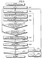
- FIG. 2 is a flowchart of an overall process procedure of the object-path predicting method and the own-vehicle-path determining method according to the embodiment.
- a moving object such as an own vehicle and another vehicle for which the prediction is performed are assumed to be moving on a two-dimensional plane.
- the object-path predicting method and the own-vehicle-path determining method according to the embodiment can be applied for controlling an object moving within a three-dimensional space or an actuator (such as a robot arm) which has any degree of freedom.
- the sensor unit 3 detects the position and the internal condition relative to the own vehicle, of a moving object such as the other vehicle present within a predetermined range, and the detected information is stored in the storage unit 7 (step S1).
- the internal condition of the object is assumed to be specified by speed (more specifically, speed v and direction ⁇ ).
- the sensor unit 3 also detects the internal condition of the own vehicle and stores the detected information in the storage unit 7.
- FIG. 3 is a detailed flowchart of a track generation process in the track generator 4.
- FIG. 3 is based on the assumption that the total number of objects (including the own vehicle) detected by the sensor unit 3 is I, and that the track generator 4 performs a calculation for generating the track N i times for each object O i (1 ⁇ i ⁇ I, i is a natural number; therefore, both I and N i are natural numbers).
- the time of track generation (track generation time) is represented by T (>0).
- initialization is performed.
- a value of a counter i for identifying the object is set to one
- a value of a counter n for indicating the number of track generations for an identical object is set to one (step S201).
- the track generator 4 reads out the result of detection by the sensor unit 3 from the storage unit 7 and sets the read result of detection as an initial state (step S202). Specifically, time t is set to zero, and an initial position (x i (0), y i (0)) and an initial internal condition (v i (0), ⁇ i (0)) are set respectively to information (x i0 , y i0 ) and (v i0 , ⁇ i0 ) input from the sensor unit 3.
- the operation selector 41 selects one operation from plural selectable operations as an operation u i (t) to be performed during a subsequent time ⁇ t according to an operation selection probability attached to each operation in advance (step S203).
- Operation selection probability p(u ic ) indicating the probability of selection of an operation u ic is defined by association between a predetermined random number and each element of a set of operations ⁇ u ic ⁇ selectable as u i (t).
- a different operation selection probability p(u ic ) may be attached to each operation u ic .
- an equal probability may be attached to all the elements in the set of operations ⁇ u ic ⁇ .
- the operation selection probability p(u ic ) can be defined by a function dependent on the position and the internal condition of the own vehicle and a surrounding road environment.
- the operation u ic includes plural elements, and contents of selectable operations are different for each type of the object O i .
- the object O i is a four-wheeled vehicle
- acceleration and angular velocity of the four-wheeled vehicle are determined according to a manner of steering and a manner of treading of an accelerator.
- the operation u ic performed on the object O i is determined based on factors such as the acceleration and the angular velocity.
- the operation u ic may be specified by the speed and the direction.
- a more specific example of the setting of the operation u ic is described.
- the acceleration is set within the range of -10 to +30 km/h/sec, and the steering angle is set within the range of -7 to +7 degrees/sec (in each case, the direction is indicated by the sign)
- the speed is set within the range of 0 to 36 km/h
- the direction is set within the range of 0 to 360 degrees.
- the quantities mentioned here are all continuous quantities. In such a case, appropriate discretization may be performed to make elements of each operation finite for forming the set of operations ⁇ u ic ⁇ .
- the object operator 42 performs the operation u ic selected in step S203 for the time ⁇ t (step S204).
- the time ⁇ t may be set approximately to 0.1 to 0.5 seconds, for example.
- the ⁇ t can be a constant value or a variable value which depends, for example, on a degree of emergency of a surrounding situation. In the following, the ⁇ t is a constant value.
- the track generation time T is an integral multiple of ⁇ t.
- the determining unit 43 determines whether the internal condition of the object O i after the operation u ic in step S204 satisfies a predetermined control condition or not (step S205). The determining unit 43 also determines whether the position of the object O i after the operation u ic is within a movable area or not (step S206).
- the control condition used in the determination in step S205 is determined according to the type of the object O i . For example, when the object O i is a four-wheeled vehicle, the control condition is determined based on the speed range after the operation in step S204 and a vehicle G with maximum acceleration after the operation in step S204.
- the movable area used in the determination in step S206 is an area such as a road (including a vehicular road and a sidewalk).
- the moving condition is satisfied.
- step S205 If any one of the conditions is not satisfied as a result of the determination by the determining unit 43 (No in step S205 or No in step S206), the process returns to step S202.
- the position and the internal condition of the object O i after the operation u ic in step S204 are found to satisfy all the conditions as a result of determination by the determining unit 43 (Yes in Step S205 and Yes in step S206)
- the time is made to advance by ⁇ t (t ⁇ t+ ⁇ t)
- the position and the internal condition after the operation in step S204 are set respectively to (x i (t), y i (t)) and (v i (t), ⁇ i (t)) (step S207).
- steps S202 to S207 described above are repeated until the track generation time T elapses. If the newly defined time t in step S207 has not reached T (No in step S208), the process returns to step S203 to repeat the processes. On the other hand, if the newly defined time t in step S207 reaches T (Yes in step S208), the track for the object O i is output and stored in the storage unit 7 (step S209).
- a track P i (m) (1 ⁇ m ⁇ N i , m is a natural number) passes through a three-dimensional time-space (x, y, t) with two space dimensions (x, y) and one time dimension (t).
- a predicted path of the object O i in the two-dimensional space (x, y) can be obtained.
- step S210 If the value of the counter n has not reached N i after step S209 (No in step S210), the value of the counter n is incremented by one (step S211), and the process returns to step S203. Then, the processes from steps S203 to S208 are repeated until the track generation time T elapses.
- FIG. 5 is an explanatory diagram schematically showing in the three-dimensional time-space, a set of tracks ⁇ P i (n) ⁇ consisting of tracks P i (1), P i (2), ..., P i (N i ) of the number N i generated for a single object O i .
- FIG. 5 is merely a schematic diagram and several thousands or more can be set as the value of Ni, for example.
- step S210 If the counter n reaches N i in step S210, and the value of the counter i for object identification has not reached the total number of objects, I (No in step S212), the value of the counter i is incremented by one and the value of the counter n for track generation counting is initialized to one (step S213). Then the process returns to step S202 and repeats the process. On the other hand, if the value of the counter i for object identification reaches I (Yes in step S212), it means that the track generation has been completed for all the objects. Thus, the track generation process in step S2 is finished and the process proceeds to step S3.
- FIG. 6 is an explanatory diagram schematically showing an example of configuration of the time-space environment Env(P).
- the time-space environment Env(P) shown in FIG. 6 consists of a set of tracks ⁇ P 1 (n) ⁇ of an objects O 1 (shown by a solid line in FIG. 6 ) and a set of tracks ⁇ P 2 (n) ⁇ of an object O 2 (shown by a broken line in FIG. 6 ).
- the time-space environment Env(P) represents a time-space environment of two objects O 1 and O 2 moving on a flat, linear road R similar to a highway in a +y-axis direction.
- the track generation is performed separately for each object without considering the correlation between the objects. Hence, sometimes the tracks of different objects intersect within the time-space.
- time-space probability density a density of a probability of presence of the object O i in each area in the time-space.
- a specific value of the track generation time T is, if set to a constant value in advance, preferably set to such a value that the probability density distribution in the time-space becomes uniform if the track generation continues after the time reaches the value T.
- the specific value of T is preferably set so that the calculation after the time reaches T is meaningless.
- the operation time ⁇ t in step S204 is approximately 0.1 to 0.5 second, a series of processes from steps S203 to S207 will be repeated 10 to 50 times for the generation of each track P i (m).
- a condition may be set so that the prediction is stopped when an increase in the degree of risk, corresponding to each increase ⁇ t in time of prediction, of each possible path of the own vehicle becomes constant.
- the setting is made so as to make end points of the possible paths of the own vehicle at a future side widely dispersed in the space, so that information can be obtained for determining a current path for securing the safety.
- the predicting unit 5 After the track generation process for each object as described above, the predicting unit 5 performs a probabilistic prediction of possible paths (path candidates) of each object such as the own vehicle and the other vehicle (step S3).
- path candidates possible paths
- the predicting unit 5 calculates the probability of selection of a specific track P i (m) among the set of tracks ⁇ P i (n) ⁇ generated for the object O i. It is obvious, however, that the following is merely an example of the predicting calculation.
- a probability p(P i (m)) of one track P i (m) becoming an actual track among N i tracks is calculated as follows. If operation series ⁇ u im (t) ⁇ for realizing the track P i (m) of the object O i is ⁇ u im (0), u im ( ⁇ t), u im (2 ⁇ t), ..., u im ,(T) ⁇ , a probability of an operation u im (t) being selected at the time t is p(u im (t)).
- the probability of presence corresponds to the time-space probability density of the set of tracks ⁇ P i (n) ⁇ in the three-dimensional time-space. In an area where the density of passing tracks is high, the probability of presence is generally high.
- FIG. 7 is a flowchart of an interference evaluation/path selection process in the interference evaluator/action selector 6. Firstly, it is checked whether the predetermined value input unit 8 makes a variable input setting on the predetermined value or not (step S401). When the variable input is made on the predetermined value (Yes in step S401), the input predetermined value is stored in the predetermined value storage unit 71 of the storage unit 7 (step S402). The predetermined value may be set in the predetermined value storage unit 71 in advance.
- a safety evaluation value indicating an evaluation of the safety of the own vehicle and an efficiency evaluation value indicating an evaluation of the driving efficiency of the own vehicle are sequentially calculated for each of the plural own-vehicle-path candidates generated and predicted by the predicting unit 5 for the own vehicle.
- the safety evaluation value and the efficiency evaluation value are used for path determination.
- a safety evaluation value S(1) and an efficiency evaluation value E(1) of a first own-vehicle-path candidate among the plural own-vehicle-path candidates are calculated .
- the safety evaluation value of the own vehicle is obtained by calculating a possibility of interference between the other vehicle and the own-vehicle-path candidate, and evaluating a degree of the possibility as a degree of interference, for example, based on a collision probability.
- the evaluation is not limited to an evaluation based on the possibility of collision, and may be a degree of interference based on a degree of shock of the collision, a degree of financial damage caused by the collision, a degree of minimum time amount of the collision.
- the efficiency evaluation value of the own vehicle is a value indicating an evaluation on how fast the vehicle can arrive the destination, for example.
- the predicted own-vehicle-path candidate obtains a higher efficiency evaluation value as a travelable distance from the current position to the destination is longer.
- the evaluation of the driving efficiency of the own vehicle may be performed for each of the predicted own-vehicle-path candidates based on various factors, for example, how smoothly the acceleration and deceleration and steering can be performed, fuel cost, predicted time till the arrival to the destination.
- FIG. 8 is a flowchart of an example of an interference degree calculation process in the own-vehicle-path safety evaluator 61.
- the object O 1 is assumed to be the own vehicle.
- the safety evaluation value is calculated as the degree of interference.
- a loop process starts for all the tracks of the own vehicle O 1 (step S441). At this time, one track in the set of tracks ⁇ P 1 (n 1 ) ⁇ is selected and the following process is performed on the selected track P 1 (m 1 ).
- a loop process starts for the other vehicle O k (step S442).
- the counter k for the identification of the other vehicle is initialized to two, and the value of the counter k is incremented every time the loop process finishes.
- a loop process (Loop3) is performed also for the other vehicle O k with respect to all the elements of the set of tracks ⁇ P k (n k ) ⁇ generated in step S3 (step S443).
- a degree of interference determined by a value n 1 for identifying the repetition of the Loop1 in other words, for identifying the track generated for the own vehicle O 1 and a counter k for identifying the other vehicle is set to r 1 (n 1 ,k), and the value of r 1 (n 1 ,k) is set to zero (step S444).
- Loop4 for evaluating the interference between the track P 1 (n 1 ) of the own vehicle O 1 and the track P k (n k ) of the other vehicle O k starts (step S445).
- the position of each track is defined as the center of the vehicle, when the difference in spatial positional coordinate (x, y) between two tracks becomes smaller than a predetermined value (such as a standard width or a length of the vehicle), the own vehicle O 1 can be regarded as colliding with the other vehicle O k .
- a predetermined value such as a standard width or a length of the vehicle
- FIG. 9 is a schematic diagram of a relation between the track P 1 (n 1 ) of the own vehicle O 1 and the track P k (n k ) of the other vehicle O k in the time-space.
- the track P 1 (n 1 ) and the track P k (n k ) intersect with each other at two points C 1 and C 2 .
- areas A 1 and A 2 exist where the distance between two tracks at the same time point is shorter than a predetermined value. Therefore, at a time when two tracks P 1 (n 1 ) and P k (n k ) are in the areas A 1 and A 2 , it is determined that the own vehicle O 1 and the other vehicle O k collide.
- FIG. 9 in the time-space environment formed according to the embodiment, even when two tracks collide once, subsequent tracks are generated. This is because the track is generated independently for each object.
- p(P k (n k )) is a value defined by formula (2) and indicates a probability of one track P k (n k ) being selected.
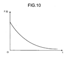
- F(t) in the last is a value giving time dependency of the inter-object interference. Therefore, when it is not necessary to give time dependency to the inter-track interference, F(t) is set to a constant value.
- F(t) may be defined as a function whose value gradually decreases over time, as shown in FIG. 10 , for example. When F(t) shown in FIG. 10 is employed, more recent collision is weighted heavier and focused.
- step S447 if the time t has not reached T (No in step S448), Loop4 is repeated. In this case, the value of t is incremented by ⁇ t (step S449), and the process returns to step S445 to repeat Loop4. On the other hand, if the time t has reached T after step S447 (Yes in step S448), Loop4 is finished. If the own vehicle O 1 does not collide with the other vehicle O k at the time t, the process directly proceeds to a determination process to determine whether to repeat Loop4 or not (step S448).
- step S450 determines whether to repeat Loop3 or not. Specifically, when the interference evaluation of any of the tracks generated for the other vehicle O k has not bee performed with respect to one track P 1 (n 1 ) of the own vehicle O 1 (No in step S450), n k is set to n k +1 (step S451) and the process returns to step S443 to repeat Loop3.
- step S450 when the interference evaluation has been performed on all the tracks generated for the other vehicle O k with respect to one track P 1 (n 1 ) of the own vehicle O 1 (Yes in step S450), it means that interference evaluation of one track P k (n k ) of the other vehicle O k has been finished. Therefore, a final degree of interference r 1 (n 1 ,k) which indicates the evaluation of interference between the track P 1 (n 1 ) of the own vehicle O 1 and all the tracks of the other vehicle O k is obtained (step S452), and the obtained value is output and stored in the storage unit 7 (step S453).
- the value of the degree of interference r 1 (n 1 ,k) output in step S453 is dependent on the probability p(P k (n k )) of the selection of one track p k (n k ) from all the tracks of the other vehicle O k .
- the degree of interference r 1 (n 1 ,k) is a sum of products of the probability p(P k (n k )) of each of the tracks P k (n k ) and the number of collisions between the track P k (n k ) and the track P 1 (n 1 ) of the own vehicle O 1 of all the elements of the set of tracks ⁇ P k (n k ) ⁇ .
- the final value obtained as the degree of interference r 1 (n 1 ,k) is proportional to the probability of collision between one track P 1 (n 1 ) of the own vehicle O 1 and the other vehicle O k .
- step S453 a determination process is performed to determine whether to repeat Loop2 or not. If there still remains the other vehicle O k for which the interference evaluation should be performed with respect to the own vehicle O 1 (No in step S454), the value of k is incremented by one (step S455) and the process returns to step S442 to repeat Loop2. On the other hand, if there is none of the other vehicle O k for which the interference evaluation should be performed with respect to the own vehicle O 1 (Yes in step S454), the process proceeds to step S456.
- step S456 the degree of interference r 1 (n 1 ,k) obtained through Loop2 to Loop4 is weighted by weight ⁇ (k)(>0) depending on the other vehicle O k .
- the value of the weight ⁇ (k) may be set equal as a constant value (for example, 1), or may be set according to a degree of danger depending on conditions such as a type of the object O k .
- the degree of total interference can be calculated for the track P 1 (n 1 ) of the own vehicle O 1 in the entire time-space environment including all the other vehicles O 2 , ..., O k .
- a degree of danger of a most dangerous object O k is treated as the degree of total interference.
- the calculated degree of total interference would not become low, as a total, whereby it is possible to avoid making a determination of safety against an intuition of a person.
- step S457 a determination process is performed to determine whether to repeat Loop1 or not. Specifically, when there still remains a track for which the interference evaluation should be performed among the set of tracks ⁇ P 1 (n 1 ) ⁇ of the own vehicle O 1 (No in step S457), the value of n 1 is incremented by one (step S458) and the process returns to step S441 to repeat Loop1. On the other hand, when there is no track remaining for which the interference evaluation should be performed in the set of tracks ⁇ P 1 (n 1 ) ⁇ of the own vehicle O 1 (Yes in step S457), the Loop1 is finished and the interference degree calculation process ends.
- the values of c 1k and F(t) used to increase the degree of interference r 1 (n 1 ,k) in step S447 are not always constant.
- the coefficient c 1k can be set to a magnitude of relative speed at the time of collision between the own vehicle O 1 and the other vehicle O k .
- a value indicating a seriousness of the damage can substitute for the coefficient c 1k .
- a correlation between the magnitude of relative speed between the vehicles at the time of collision and a damage scale evaluation value, which is a quantified evaluation of a damage scale, and/or an amount of financial damage may be found and stored in the storage unit 7, and the stored value may be read out from the storage unit 7 and assigned to the coefficient c 1k .
- the damage scale evaluation value and/or an amount of financial damage may be determined according to the type of objects. In this case, it may be preferable if the possibility of collision with a person can be reduced as far as possible by, for example, setting an extremely large c 1k value for the collision with a person in comparison with a collision with a vehicle.
- evaluation can be made based on a traveling distance y during an operation time interval ⁇ t (for example, 0.1 second or 0.5 second) on each of the predicted own-vehicle-path candidates, or a traveling distance y during a control time tmax (for example, 5 seconds). As the traveling distance y becomes longer, the efficiency evaluation value increases.
- ⁇ t for example, 0.1 second or 0.5 second
- a safe path "safetypath” and an optimal path “bestpath” are each initialized to “non” (meaning there is no such path) (step S403).
- Variable i is set to one (step S404), and a safety evaluation value S(i) (corresponding to the degree of total interference in the description of FIG. 8 ) and an efficiency evaluation value E(i) of an i th own-vehicle-path candidate are calculated (step S405).
- a safety evaluation value S(i) (corresponding to the degree of total interference in the description of FIG. 8 ) and an efficiency evaluation value E(i) of an i th own-vehicle-path candidate are calculated (step S405).
- safetypath is not “non” (none), (No in step S406), it is determined whether the calculated safety evaluation value S(i) is smaller than a minimum value Smin of the safety evaluation value or not (step S407).
- the minimum value Smin of the safety evaluation value is set to S(i) and "safetypath” is set to i (which indicates the i th own-vehicle-path candidate) (step S408).
- step S410 it is determined whether the safety evaluation value S(i) satisfies safety condition by exceeding a predetermined value set in the predetermined value storage unit 71 (step S410).
- “exceeding a predetermined value” means that the safety evaluation value indicates a value lower than the set predetermined value and thereby having a higher safety than that of the predetermined value (in other words, having a lower risk).
- step S411 it is determined whether the calculated efficiency evaluation value E(i) is larger than a maximum value Emax of the efficiency evaluation value or not (step S412).
- the maximum value Emax of the efficiency evaluation value is set to E(i)
- “bestpath” is set to i (which indicates the it own-vehicle-path candidate) (step S413).
- step S414 the variable i is incremented by +1 (step S414) and the same processes are repeated for each of the all predicted own-vehicle-path candidates (step S415).
- "safetypath” found in step S408 is set as “bestpath” (step S416).
- operation information of the optimal path "bestpath” i found in step S413 or step S416 is output to the side of the output terminal 9 (step S417).
- the i th own-vehicle-path candidate is selected as the drivable path of the own vehicle and information concerning x(t) and u(t) corresponding to the i th own-vehicle-path candidate (track) is output to the side of the output terminal 9.
- a predetermined value which is optionally set within the range satisfying the safety standard
- the selection of a passing path can be accepted so that the own vehicle can arrive the destination faster, whereby realistic determination of the own-vehicle path harmonizing the safety and the driving efficiency can be realized.
- an actuator unit which corresponds to the output terminal 9 is a steering, an accelerator, or a brake itself that is directly driven by an electric control system serving for the automatic driving
- the operation of the steering, the accelerator, or the brake can be performed directly using an operation signal (corresponding to x(t) and u(t) of the selected track) output from the setting-based most-efficient path selector 63.
- the actuator unit which corresponds to the output terminal 9 is an actuator which operates the steering, an accelerator pedal, or a brake pedal (corresponding to legs and hands of the driver)
- an operation torque is calculated based on an operation signal (corresponding to x(t) and u(t) of the selected track) output from the setting-based most-efficient path selector 63, and the calculated torque may be applied to the steering, the accelerator, or the brake for the operation.
- the apparatus can be applied not only for the automatic driving but also for a driving operation supporting apparatus.
- the predetermined value input unit 8 may be an accelerator pedal, and the predetermined value may be made variably set in such a manner that the predetermined value increases from an initially-set value according to a tread amount of the accelerator pedal by the driver.
- the driver knows that the driving risk related with the driving of the own vehicle increases as the tread amount of the accelerator pedal increases from a current driving state.
- the increased tread amount can be regarded as a manifestation of the driver's will to prioritize the driving efficiency (in other words, to arrive the destination faster).
- the variable setting of the predetermined value (increasing the driving risk) linked with the tread amount of the accelerator pedal can be regarded as a realistic measure.
- the predetermined value input unit 8 can be a brake pedal, and the predetermined value may be variably set in such a manner that the predetermined value decreases from an initially-set value or from a current set value according to a tread amount of the brake pedal by the driver.
- the increased tread amount of the brake pedal from the current driving state can be regarded as a manifestation of the driver's will to avoid the driving risk of the driving of the own-vehicle as much as possible.
- the variable setting of the predetermined value (lowering the driving risk) linked with the tread amount of the brake pedal can also be regarded as a realistic measure.
- the predetermined value input unit 8 is a mode-selecting switch (or levers) related with the driving mode, and the driving mode includes a luxury mode and a sport mode
- the predetermined value may be variably set in such a manner that the predetermined value increases from an initially-set value according to an operation by the driver to select the sport mode. Since the driver knows that the driving risk in the driving of the own vehicle increases by the selection of the sport mode, such selection can be regarded as a manifestation of driver's will to prioritize the driving efficiency by speeding up (in other words, to arrive the destination faster).
- the variable setting of the predetermined value linked with the selecting operation of the mode-selecting switch can be regarded as a realistic measure.
- an upper limit of the predetermined variable value which defines the acceptable level of the safety evaluation value can be set by an auto insurance company to a fixed value in an unchangeable state in accordance with an amount of premium of insurance.
- the upper limit which defines the variable range of the predetermined value which can be varied through the operation of the accelerator pedal and the like may be fixedly set in advance according to the insurance contract between the insurance company and an individual driver.
- the insurance company may make an insurance contract with an individual driver of the own vehicle at a premium amount corresponding to the value of the upper limit.
- the upper limit defines the acceptable range of a degree of danger.
- the upper limit the driver accepts is high, the driving risk is also high. Hence, the premium of the insurance is high.
- the upper limit the driver accepts is low, the driving risk is also low, and hence, the premium of the insurance can be low.
- a suitable insurance contract can be made in view of the driving risk and the driving efficiency.
- the safety evaluation value which indicates the evaluation of the safety of the own vehicle is used as a first evaluation value
- the efficiency evaluation value which indicates the evaluation of the driving efficiency of the own vehicle is used as a second evaluation value.
- the first and the second evaluation values can be evaluation values other than the safety evaluation value and the efficiency evaluation value.
- the own-vehicle-path candidate is selected based on the second evaluation value, it is not necessary that a selected own-vehicle-path candidate has a maximum second evaluation value, instead an own-vehicle-path candidate with a second highest second evaluation value, or a third highest second evaluation value may be selected.
- any of the own-vehicle-path candidates can be selected as far as the second evaluation value of the selected own-vehicle-path candidate is not lowest.
- an own-vehicle path is determined from plural own-vehicle-path candidates, it is possible to first select own-vehicle-path candidates with high first evaluation values, then select own-vehicle-path candidates with high second evaluation values as appropriate own-vehicle-path candidates from the selected own-vehicle-path candidates, and select any one of the appropriate own-vehicle-path candidates.
- the own-vehicle-path determining method and the own-vehicle-path determining apparatus according to the present invention are useful for determining one of plural predicted own-vehicle-path candidates as an optimal drivable path, and more particularly are suitable for realizing automatic driving of an own vehicle.
Description
- The present invention relates to own-vehicle-path determining methods and own-vehicle-path determining apparatuses which determine one own-vehicle-path candidate as an optimal drivable path from plural predicted own-vehicle-path candidates, and more particularly, to own-vehicle-path determining methods and own-vehicle-path determining apparatuses suitable for automatic driving of an own vehicle.
- Document
US 6,169 495 discloses a vehicle traffic control system which is designed such that no conflicts at road intersections are caused. For this, matrices are generated, which are based on the present position, speed and destination of each vehicle, based on which vectors indicating possible courses for each vehicle are generated. - Document
WO 00/40929 - Document
WO 03/025507 - In recent years, various attempts have been made to realize automatic driving of automobiles. For the realization of the automatic driving of automobiles, it is important to correctly detect objects around the vehicle such as vehicles, pedestrians, and obstacles, and to avoid dangers based on the result of detection while the vehicle is running. As a technique for detecting surrounding objects with high accuracy, object-detecting techniques utilizing various types of sensors and radars are known.
- On the other hand, as a technique for avoiding dangers during driving, techniques for a system of plural objects and an own vehicle are known, which use information about position and speed of the own vehicle and information about positions and speed of plural objects other than the own vehicle to generate expected paths of objects including the own vehicle, and predict a possibility of collision of two objects among the objects constituting the system (see, for example, Nonpatent Literature 1). This technique predicts possible paths of all the objects constituting the system according to operation series of same framework based on a concept of probability, and outputs the predicted paths. Thereafter, a path, according to which the safest situation is realized for the entire system including the own vehicle, is found and output based on the predicted results.
- Nonpatent Literature 1: Broadhurst, S. Baker, and T. Kanade, "Monte Carlo Road Safety Reasoning", IEEE Intelligent Vehicle Symposium (IV2005), IEEE, (2005 June)
- However, the path found through the prediction by the technique described in
Nonpatent Literature 1 is often unreasonable because this technique focuses on predicting a path which is safe for all the objects constituting the system. For example, on a highway, if a vehicle is running ahead of an own vehicle at a lower speed on the same driving lane, a driver of the own vehicle may think he/she can pass. However, since it is safer to simply follow the other slower vehicle, a path following the other vehicle is selected as a safe path based on the prediction. Then, sometimes the arrival to the destination is delayed. In brief, though such techniques may realize an extremely high driving safety, its driving efficiency can be extremely low. - The present invention is made in view of the above, and an object of the present invention is to provide an own-vehicle-path determining method and an own-vehicle-path determining apparatus which can determine an appropriate own-vehicle path from plural predicted own-vehicle-path candidates.
- This object is solved by an own-vehicle-path determining method as set out in
claim 1, and alternatively by an own-vehicle-path determining apparatus as set out inclaim 8. - Advantageous developments are defined in the dependent claims.
- The own-vehicle-path determining method and the own-vehicle-path determining apparatus according to the present invention calculate the first evaluation value and the second evaluation value of the own vehicle relative to each of the plural predicted own-vehicle-path candidates, select own-vehicle-path candidates with a high first evaluation value and a high second evaluation value as appropriate own-vehicle-path candidates from the plural own-vehicle-path candidates, and select any one of the appropriate own-vehicle-path candidates as an own-vehicle path, whereby an appropriate own-vehicle path can be determined through an appropriate setting of the first evaluation value and the second evaluation value.
- Further, the own-vehicle-path determining method and the own-vehicle-path determining apparatus according to the present invention calculate the first evaluation value and the second evaluation value of the own vehicle relative to each of the plural predicted own-vehicle-path candidates, and select an own-vehicle-path candidate having a maximum second evaluation value among those having a high first evaluation value from the plural own-vehicle-path candidates as a drivable path of the own vehicle, whereby an appropriate own-vehicle path can be determined through an appropriate setting of the first evaluation value and the second evaluation value.
- Specifically, since the own-vehicle-path determining method and the own-vehicle-path determining apparatus according to the present invention calculate the first evaluation value which indicates an evaluation of the safety of the own vehicle relative to each of the plural predicted own-vehicle-path candidates and the second evaluation value which indicates an evaluation of driving efficiency of each of the own-vehicle-path candidates, and select an own-vehicle-path candidate having a maximum second evaluation value among those having a first evaluation value higher than a set predetermined value as a drivable path of the own vehicle from the plural own-vehicle-path candidates, whereby an own-vehicle path can be determined through an appropriate setting of the predetermined value, which is used for accepting the first evaluation value, depending on a situation while safety and driving efficiency are harmonized in a realistic manner. For example, selection of a passing path is accepted so as to realize early arrival at the destination even though the safety is slightly compromised within a range satisfying the safety standard.
-
-
FIG. 1 is a schematic block diagram of a functional configuration of an own-vehicle-path determining apparatus according to one embodiment of the present invention; -
FIG. 2 is a flowchart of an overall process procedure of an object-path predicting method and an own-vehicle-path determining method according to one embodiment; -
FIG. 3 is a detailed flowchart of a track generation process in a track generator; -
FIG. 4 is a schematic diagram of a generated track in a three-dimensional time-space; -
FIG. 5 is a schematic diagram of a generated set of tracks of one object in a three-dimensional time-space; -
FIG. 6 is a schematic diagram of a configuration of a time-space environment formed by the object-path predicting method; -
FIG. 7 is a flowchart of an example of a path determination process in an interference evaluator/action selector; -
FIG. 8 is a flowchart of an example of an interference degree calculation process in an own-vehicle-path safety evaluator; -
FIG. 9 is a schematic diagram showing a relation between a track of an own vehicle and a track of another vehicle in a time-space; -
FIG. 10 is a characteristic graph indicating time dependence of inter-object interference; and -
FIG. 11 is a schematic diagram of an example of interference evaluation based on a degree of total interference between an own vehicle and other vehicles in the time-space environment. -
- 1
- Own-vehicle-path determining apparatus
- 6
- Interference evaluator/action selector
- 8
- Predetermined value input unit
- 61
- Own-vehicle-path safety evaluator
- 62
- Own-vehicle-path efficiency evaluator
- 63
- Setting-based most-efficient path selector
- Exemplary embodiments of an own-vehicle-path determining method and an own-vehicle-path determining apparatus according to the present invention will be described in detail below with reference to the accompanying drawings. The present invention is not limited by the embodiments. Various modifications can be made to the embodiments without departing from the scope of the present invention.
-
FIG. 1 is a schematic block diagram of a functional configuration of an own-vehicle-path determining apparatus according to one embodiment of the present invention. The own-vehicle-path determining apparatus is mounted on an own vehicle, which is an automobile running on a road, to detect obstacles such as other vehicles present within a predetermined surrounding range of the own vehicle and determine an own-vehicle path for automatically driving the own vehicle in consideration of detected obstacles. - An own-vehicle-
path determining apparatus 1 according to the embodiment includes aninput unit 2 which inputs various information from outside, a sensor unit 3 which detects a position and an internal condition of an object present within a predetermined range, a track generator 4 which, based on a result of detection by the sensor unit 3, generates a track representing a possible positional change of an object over time in a time-space configured with time and space, a predictingunit 5 which makes a probabilistic prediction of a path of an object such as the own vehicle and the other vehicle using a track generated by the track generator 4, an interference evaluator/action selector 6 which calculates possibility of interference between the own vehicle and the other vehicle based on the result of prediction of the object in the predictingunit 5 to select an optimal drivable path as the own-vehicle path, astorage unit 7 which stores information such as a track in the time-space generated by the track generator 4 and a result of prediction by the predictingunit 5, a predeterminedvalue input unit 8 which serves to input and set a predetermined value in thestorage unit 7 so as to be used in the interference evaluator/action selector 6, and an output terminal 9 which receives an output result (operation signal) selected by the interference evaluator/action selector 6. - The
input unit 2 has a function of receiving an input of information such as various types of setting information for the prediction of paths of moving objects such as the own vehicle and the other vehicle. Theinput unit 2 is implemented with a remote control, a keyboard (including touchscreen-type devices which allow input from a display), a pointing device (such as a mouse and a track pad), for example. Alternatively, a microphone can be arranged as theinput unit 2 so that information can be input via voice. - The sensor unit 3 is implemented with a millimeter-wave radar, a laser radar, an image sensor, and the like. The sensor unit 3 includes variety of sensors such as a speed sensor, an acceleration sensor, a rudder angle sensor, and an angular velocity sensor, and is able to detect moving condition of the own vehicle. An internal condition of the object detected by the sensor unit 3 has significance in prediction of objects, and preferably is a physical value such as speed, acceleration, angular velocity, and angular acceleration of the object. Here, the physical value, such as speed and angular velocity of the moving object such as an own vehicle can be zero (which means that the object is in a halt) naturally.
- The track generator 4 includes an
operation selector 41 which selects an operation for a moving object such as the own vehicle and the other vehicle from plural operations, anobject operator 42 which performs an operation selected by theoperation selector 41 for a predetermined time period, and a determiningunit 43 which determines whether the position and the internal condition of the moving object such as the own vehicle and the other vehicle satisfy a predetermined condition after the operation by theobject operator 42. The predictingunit 5 performs a probabilistic predicting calculation of the path of the object using the track output from the track generator 4 for each moving object such as the own vehicle and the other vehicle. - The interference evaluator/
action selector 6 includes an own-vehicle-path safety evaluator 61 which calculates a safety evaluation value (first evaluation value) indicating an evaluation of the safety of the own vehicle by calculating a possibility of interference such as collision between the other vehicle and each of the plural own-vehicle-path candidates predicted by the predictingunit 5, an own-vehicle-path efficiency evaluator 62 which calculates an efficiency evaluation value (second evaluation value which is an evaluation value indicating how fast the vehicle can reach the destination, for example) which indicates an evaluation of driving efficiency of each of the plural own-vehicle-path candidates predicted by the predictingunit 5, and a setting-based most-efficient path selector 63 which selects, as a drivable path of the own vehicle, an own-vehicle-path candidate whose safety evaluation value satisfies safety condition by exceeding a predetermined set value and which has a highest efficient evaluation value among the plural own-vehicle-path candidates. - The predetermined
value input unit 8 allows setting and input of a predetermined value to be employed in the process by the setting-based most-efficient path selector 63 for determining whether the safety evaluation value of each own-vehicle-path candidate is acceptable in terms of safety. For example, an accelerator pedal, a brake pedal, and a mode-selecting switch of driving modes (which switches between, for example, a sport mode and a luxury mode) can be adopted as the predeterminedvalue input unit 8. - The
storage unit 7 stores operations for the selection by theoperation selector 41 of the track generator 4, in addition to the track generated by the track generator 4 and the result of prediction by the predictingunit 5. Further, thestorage unit 7 includes a predeterminedvalue storage unit 71 which stores a predetermined value input and set by the predeterminedvalue input unit 8, and supplies the stored predetermined value to the setting-based most-efficient path selector 63 for the determination process. Thestorage unit 7 is implemented with a Read Only Memory (ROM) which previously stores therein a program that starts up a predetermined Operation System (OS), an object-path predicting program, an own-vehicle path determining program, and the like according to the embodiment, and a Random Access Memory (RAM) which stores therein operation parameters, data, and the like for each process. Alternatively, thestorage unit 7 can be implemented with an interface and a computer-readable recording medium corresponding to the interface in such a manner that the computer-readable recording medium can be mounted in the interface provided in the own-vehicle-path determining apparatus 1. - In the own-vehicle-
path determining apparatus 1 with the above-described functional configuration, the track generator 4, the predictingunit 5, the interference evaluator/action selector 6, and thestorage unit 7 are implemented with a processor (computer) 10 provided with a Central Processing Unit (CPU) which has calculation and control functions. The CPU of the own-vehicle-path determining apparatus 1 executes calculation processes related with the object-path predicting method and the own-vehicle-path determining method according to the embodiment by reading out the information stored in thestorage unit 7 and a variety of programs such as the object-path predicting program and the own-vehicle-path determining program from thestorage unit 7. - The object-path predicting program and the own-vehicle-path determining program according to the embodiment can be recorded on a computer-readable recording medium such as a hard disk, flexible disk, CD-ROM, DVD-ROM, flash memory, and MO disk, and widely distributed.
- The object-path predicting method and the own-vehicle-path determining method according to the embodiment of the present invention will be described.
FIG. 2 is a flowchart of an overall process procedure of the object-path predicting method and the own-vehicle-path determining method according to the embodiment. In the following description, a moving object such as an own vehicle and another vehicle for which the prediction is performed are assumed to be moving on a two-dimensional plane. However, the object-path predicting method and the own-vehicle-path determining method according to the embodiment can be applied for controlling an object moving within a three-dimensional space or an actuator (such as a robot arm) which has any degree of freedom. - Firstly, the sensor unit 3 detects the position and the internal condition relative to the own vehicle, of a moving object such as the other vehicle present within a predetermined range, and the detected information is stored in the storage unit 7 (step S1). Hereafter, the internal condition of the object is assumed to be specified by speed (more specifically, speed v and direction θ). In step S1, the sensor unit 3 also detects the internal condition of the own vehicle and stores the detected information in the
storage unit 7. - The track generator 4 generates future tracks of each moving object such as the own vehicle and the other vehicle using the result of detection input by the sensor unit 3 (step S2).
FIG. 3 is a detailed flowchart of a track generation process in the track generator 4.FIG. 3 is based on the assumption that the total number of objects (including the own vehicle) detected by the sensor unit 3 is I, and that the track generator 4 performs a calculation for generating the track Ni times for each object Oi (1≤i≤I, i is a natural number; therefore, both I and Ni are natural numbers). The time of track generation (track generation time) is represented by T (>0). - Firstly, initialization is performed. In the initialization, a value of a counter i for identifying the object is set to one, and a value of a counter n for indicating the number of track generations for an identical object is set to one (step S201).
- Secondly, the track generator 4 reads out the result of detection by the sensor unit 3 from the
storage unit 7 and sets the read result of detection as an initial state (step S202). Specifically, time t is set to zero, and an initial position (xi(0), yi(0)) and an initial internal condition (vi(0), θi(0)) are set respectively to information (xi0, yi0) and (vi0, θi0) input from the sensor unit 3. - Subsequently, the
operation selector 41 selects one operation from plural selectable operations as an operation ui(t) to be performed during a subsequent time Δt according to an operation selection probability attached to each operation in advance (step S203). Operation selection probability p(uic) indicating the probability of selection of an operation uic is defined by association between a predetermined random number and each element of a set of operations {uic} selectable as ui(t). A different operation selection probability p(uic) may be attached to each operation uic. Alternatively, an equal probability may be attached to all the elements in the set of operations {uic}. In the latter case, p(uic)=1/(total number of selectable operations). Further, the operation selection probability p(uic) can be defined by a function dependent on the position and the internal condition of the own vehicle and a surrounding road environment. - In general, the operation uic includes plural elements, and contents of selectable operations are different for each type of the object Oi. For example, if the object Oi is a four-wheeled vehicle, acceleration and angular velocity of the four-wheeled vehicle are determined according to a manner of steering and a manner of treading of an accelerator. In view of this, when the object Oi is the four-wheeled vehicle, the operation uic performed on the object Oi is determined based on factors such as the acceleration and the angular velocity. On the other hand, when the object Oi is a person, the operation uic may be specified by the speed and the direction.
- A more specific example of the setting of the operation uic is described. When the object Oi is an automobile, the acceleration is set within the range of -10 to +30 km/h/sec, and the steering angle is set within the range of -7 to +7 degrees/sec (in each case, the direction is indicated by the sign), whereas when the object Oi is a person, the speed is set within the range of 0 to 36 km/h, and the direction is set within the range of 0 to 360 degrees. The quantities mentioned here are all continuous quantities. In such a case, appropriate discretization may be performed to make elements of each operation finite for forming the set of operations {uic}.
- Subsequently, the
object operator 42 performs the operation uic selected in step S203 for the time Δt (step S204). The time Δt may be set approximately to 0.1 to 0.5 seconds, for example. The Δt can be a constant value or a variable value which depends, for example, on a degree of emergency of a surrounding situation. In the following, the Δt is a constant value. The track generation time T is an integral multiple of Δt. - Subsequently, the determining
unit 43 determines whether the internal condition of the object Oi after the operation uic in step S204 satisfies a predetermined control condition or not (step S205). The determiningunit 43 also determines whether the position of the object Oi after the operation uic is within a movable area or not (step S206). The control condition used in the determination in step S205 is determined according to the type of the object Oi. For example, when the object Oi is a four-wheeled vehicle, the control condition is determined based on the speed range after the operation in step S204 and a vehicle G with maximum acceleration after the operation in step S204. On the other hand, the movable area used in the determination in step S206 is an area such as a road (including a vehicular road and a sidewalk). Hereafter, when the object is within the movable area, it is said that "the moving condition is satisfied". - If any one of the conditions is not satisfied as a result of the determination by the determining unit 43 (No in step S205 or No in step S206), the process returns to step S202. On the other hand, if the position and the internal condition of the object Oi after the operation uic in step S204 are found to satisfy all the conditions as a result of determination by the determining unit 43 (Yes in Step S205 and Yes in step S206), the time is made to advance by Δt (t←t+Δt), and the position and the internal condition after the operation in step S204 are set respectively to (xi(t), yi(t)) and (vi(t), θi(t)) (step S207).
- The processes in steps S202 to S207 described above are repeated until the track generation time T elapses. If the newly defined time t in step S207 has not reached T (No in step S208), the process returns to step S203 to repeat the processes. On the other hand, if the newly defined time t in step S207 reaches T (Yes in step S208), the track for the object Oi is output and stored in the storage unit 7 (step S209).
-
FIG. 4 is a schematic diagram of a track generated for the object Oi through the series of processes from steps S203 to S207 repeated over the time t =0, Δt, 2Δt, ..., T. InFIG. 4 , a track Pi(m) (1≤m≤Ni, m is a natural number) passes through a three-dimensional time-space (x, y, t) with two space dimensions (x, y) and one time dimension (t). When the track Pi(m) is projected onto an x-y plane, a predicted path of the object Oi in the two-dimensional space (x, y) can be obtained. - If the value of the counter n has not reached Ni after step S209 (No in step S210), the value of the counter n is incremented by one (step S211), and the process returns to step S203. Then, the processes from steps S203 to S208 are repeated until the track generation time T elapses.
- When the value of the counter n reaches Ni in step S210 (Yes in step S210), the generation of all the tracks for the object Oi is completed.
FIG. 5 is an explanatory diagram schematically showing in the three-dimensional time-space, a set of tracks {Pi(n)} consisting of tracks Pi(1), Pi(2), ..., Pi(Ni) of the number Ni generated for a single object Oi. A starting point of each track as an element of the set of tracks {Pi(n)}, in other words, an initial position (xi0, yi0, 0) is identical (see step S202).FIG. 5 is merely a schematic diagram and several thousands or more can be set as the value of Ni, for example. - If the counter n reaches Ni in step S210, and the value of the counter i for object identification has not reached the total number of objects, I (No in step S212), the value of the counter i is incremented by one and the value of the counter n for track generation counting is initialized to one (step S213). Then the process returns to step S202 and repeats the process. On the other hand, if the value of the counter i for object identification reaches I (Yes in step S212), it means that the track generation has been completed for all the objects. Thus, the track generation process in step S2 is finished and the process proceeds to step S3.
- When the track generation process is performed for a predetermined times for all the objects detected by sensor unit 3, a time-space environment Env(P) is formed. The time-space environment Env(P) is configured with a set of tracks which the plural objects present in the predetermined range within the three-dimensional time-space can take.
FIG. 6 is an explanatory diagram schematically showing an example of configuration of the time-space environment Env(P). The time-space environment Env(P) shown inFIG. 6 consists of a set of tracks {P1(n)} of an objects O1 (shown by a solid line inFIG. 6 ) and a set of tracks {P2(n)} of an object O2 (shown by a broken line inFIG. 6 ). More specifically, the time-space environment Env(P) represents a time-space environment of two objects O1 and O2 moving on a flat, linear road R similar to a highway in a +y-axis direction. In the embodiment, the track generation is performed separately for each object without considering the correlation between the objects. Hence, sometimes the tracks of different objects intersect within the time-space. - In
FIG. 6 , a per unit volume density of the set of tracks {Pi(n)} (i=1, 2) within each area in the time-space is a density of a probability of presence of the object Oi in each area in the time-space (hereinafter referred to "time-space probability density"). Hence, the probability of the object Oi passing through a predetermined area in the three-dimensional time-space can be found based on the time-space environment Env(P) formed by the track generation process in step S2. Since the time-space probability density is merely a probabilistic concept for this time-space, sum of time-space probability densities for one object within the time-space is not always one. - A specific value of the track generation time T is, if set to a constant value in advance, preferably set to such a value that the probability density distribution in the time-space becomes uniform if the track generation continues after the time reaches the value T. Namely, the specific value of T is preferably set so that the calculation after the time reaches T is meaningless. For example, when the object is a four-wheeled vehicle in a normal driving, T is set to a value as low as approximately 5 seconds (T=5). In this case, if the operation time Δt in step S204 is approximately 0.1 to 0.5 second, a series of processes from steps S203 to S207 will be repeated 10 to 50 times for the generation of each track Pi(m).
- In addition, it is preferable to set a different value as the track generation time T for each type of roads such as a highway, an open road, and a two-lane road, and switch from one value to another by using a method of reading out a type of a road on which the own vehicle is currently running from map data based on positional data, or using a method of reading out a type of a road using a road recognizing apparatus utilizing image recognition and the like.
- Further, it is preferable to statistically evaluate the probability density distribution in the time-space based on the tracks obtained through calculation before the track generation time T elapses, and to perform adaptive control so as to shorten the track generation time T when the distribution is uniform and lengthen the track generation time T when the distribution is not uniform.
- Further, it is possible to prepare (plural) possible paths of the own vehicle in advance, and perform the prediction only up to the track generation time T after which the probability of the own-vehicle path intersecting with the path of other object is constant. In this case, a condition may be set so that the prediction is stopped when an increase in the degree of risk, corresponding to each increase Δt in time of prediction, of each possible path of the own vehicle becomes constant. When such configuration is adopted, needless to say, the setting is made so as to make end points of the possible paths of the own vehicle at a future side widely dispersed in the space, so that information can be obtained for determining a current path for securing the safety.
- After the track generation process for each object as described above, the predicting
unit 5 performs a probabilistic prediction of possible paths (path candidates) of each object such as the own vehicle and the other vehicle (step S3). Hereinbelow, as a specific example of the predicting calculation process in the predictingunit 5, a calculation of the probability of selection of a specific track Pi(m) among the set of tracks {Pi(n)} generated for the object Oi will be described. It is obvious, however, that the following is merely an example of the predicting calculation. - When the Ni number of the tracks (path candidates) are generated for the object Oi, a probability p(Pi(m)) of one track Pi(m) becoming an actual track among Ni tracks is calculated as follows. If operation series {uim(t)} for realizing the track Pi(m) of the object Oi is {uim(0), uim(Δt), uim(2Δt), ..., uim,(T)}, a probability of an operation uim(t) being selected at the time t is p(uim(t)). Hence, the probability of the operation series {uim(t)} being performed over time t=0 to T is:


- If all the operations uim(t) are selected with an equal probability p0 (where 0<p0<1), the formula (1) becomes

Hence, the sum of the probabilities of the tracks Pi(m) included in the possible Ni tracks of the object Oi is, if the number of discretization steps from t=0 to t=T is represented as s, represented as Nkp0 s. The probability p(Pi(m)) of one track Pi(m) among them being selected is, with the substitution of formula (3) into the formula (2):
Thus, the probability p(Pi(m)) is not dependent on the track Pi(m). - If the number of generated tracks (path candidates) is the same for all the objects (and is N) in the formula (4), p(Pi(m))=1/N and is constant regardless of the objects Oi, since the N1 = N2 =...= NI = N (constant value). In this case, the standardization of the value of probability p(Pi(m)) to one can simplify the predicting calculation in the predicting
unit 5 and allow for more rapid operation of a predetermined predicting calculation. - The predicting
unit 5 finds the probability of presence of the object Oi per unit volume in each area of the tree-dimensional time-space based on the probability p(Pi(m)) calculated for each of the objects Oi (i=1, 2, ..., I). The probability of presence corresponds to the time-space probability density of the set of tracks {Pi(n)} in the three-dimensional time-space. In an area where the density of passing tracks is high, the probability of presence is generally high. - Subsequent to step S3 described above, the interference evaluator/
action selector 6 determines an optimal path of the own vehicle while evaluating the interference between the own vehicle and the other vehicle based on the result of prediction in the predicting unit 5 (step S4) and outputs the result to the output terminal 9 (step S5).FIG. 7 is a flowchart of an interference evaluation/path selection process in the interference evaluator/action selector 6. Firstly, it is checked whether the predeterminedvalue input unit 8 makes a variable input setting on the predetermined value or not (step S401). When the variable input is made on the predetermined value (Yes in step S401), the input predetermined value is stored in the predeterminedvalue storage unit 71 of the storage unit 7 (step S402). The predetermined value may be set in the predeterminedvalue storage unit 71 in advance. - Then, a safety evaluation value indicating an evaluation of the safety of the own vehicle and an efficiency evaluation value indicating an evaluation of the driving efficiency of the own vehicle are sequentially calculated for each of the plural own-vehicle-path candidates generated and predicted by the predicting
unit 5 for the own vehicle. The safety evaluation value and the efficiency evaluation value are used for path determination. Firstly, a safety evaluation value S(1) and an efficiency evaluation value E(1) of a first own-vehicle-path candidate among the plural own-vehicle-path candidates are calculated . The safety evaluation value of the own vehicle is obtained by calculating a possibility of interference between the other vehicle and the own-vehicle-path candidate, and evaluating a degree of the possibility as a degree of interference, for example, based on a collision probability. As the degree of interference increases, the possibility of collision and the like of the other vehicle increases. The evaluation is not limited to an evaluation based on the possibility of collision, and may be a degree of interference based on a degree of shock of the collision, a degree of financial damage caused by the collision, a degree of minimum time amount of the collision. The efficiency evaluation value of the own vehicle is a value indicating an evaluation on how fast the vehicle can arrive the destination, for example. The predicted own-vehicle-path candidate obtains a higher efficiency evaluation value as a travelable distance from the current position to the destination is longer. The evaluation of the driving efficiency of the own vehicle may be performed for each of the predicted own-vehicle-path candidates based on various factors, for example, how smoothly the acceleration and deceleration and steering can be performed, fuel cost, predicted time till the arrival to the destination. - Referring to
FIG. 8 , the interference evaluation process for calculating the safety evaluation value in the step described above and in step S405 mentioned later, and the like will be described.FIG. 8 is a flowchart of an example of an interference degree calculation process in the own-vehicle-path safety evaluator 61. In the following description, the object O1 is assumed to be the own vehicle. Further, for the convenience of description, other objects Ok (k=2, 3, ..., K) are all assumed to be four-wheeled vehicles, and collectively referred to as other vehicle Ok. The interference evaluation process shown inFIG. 8 includes four loop processes, and evaluates the interference between all elements of the set of tracks {P1(n1)} of the own vehicle O1 found in step S3 and all sets of tracks {Pk(nk)} of the other vehicle Ok. The safety evaluation value is calculated as the degree of interference. - Firstly, a loop process (Loop1) starts for all the tracks of the own vehicle O1 (step S441). At this time, one track in the set of tracks {P1(n1)} is selected and the following process is performed on the selected track P1(m1).
- Secondly, a loop process (Loop2) starts for the other vehicle Ok (step S442). In the Loop2, the counter k for the identification of the other vehicle is initialized to two, and the value of the counter k is incremented every time the loop process finishes.
- A loop process (Loop3) is performed also for the other vehicle Ok with respect to all the elements of the set of tracks {Pk(nk)} generated in step S3 (step S443). In the loop process, a degree of interference determined by a value n1 for identifying the repetition of the Loop1, in other words, for identifying the track generated for the own vehicle O1 and a counter k for identifying the other vehicle is set to r1(n1,k), and the value of r1(n1,k) is set to zero (step S444).
- Subsequently, a loop process (Loop4) for evaluating the interference between the track P1(n1) of the own vehicle O1 and the track Pk(nk) of the other vehicle Ok starts (step S445). In Loop4, a difference in positional coordinate (x, y) between the two tracks P1(n1) and Pk(nk) is sequentially obtained at time t=0, Δt, ..., T. Since the position of each track is defined as the center of the vehicle, when the difference in spatial positional coordinate (x, y) between two tracks becomes smaller than a predetermined value (such as a standard width or a length of the vehicle), the own vehicle O1 can be regarded as colliding with the other vehicle Ok.
-
FIG. 9 is a schematic diagram of a relation between the track P1(n1) of the own vehicle O1 and the track Pk(nk) of the other vehicle Ok in the time-space. InFIG. 9 , the track P1(n1) and the track Pk(nk) intersect with each other at two points C1 and C2. Hence, around the two points C1 and C2, areas A1 and A2 exist where the distance between two tracks at the same time point is shorter than a predetermined value. Therefore, at a time when two tracks P1(n1) and Pk(nk) are in the areas A1 and A2, it is determined that the own vehicle O1 and the other vehicle Ok collide. As is obvious fromFIG. 9 , in the time-space environment formed according to the embodiment, even when two tracks collide once, subsequent tracks are generated. This is because the track is generated independently for each object. - After the difference in the positional coordinate (x, y) is found, when the own vehicle O1 and the other vehicle Ok collide in the sense as described above (Yes in step S446), the value of the degree of interference r1(n1,k) is increased as follows (step S447):

A second term clk•p(Pk(nk))•F(t) will be described. Firstly, clk is a positive constant value, and can be set as clk=1, for example. Further, p(Pk(nk)) is a value defined by formula (2) and indicates a probability of one track Pk(nk) being selected. Further, F(t) in the last is a value giving time dependency of the inter-object interference. Therefore, when it is not necessary to give time dependency to the inter-track interference, F(t) is set to a constant value. On the other hand, when the time dependency is given to the inter-track interference, F(t) may be defined as a function whose value gradually decreases over time, as shown inFIG. 10 , for example. When F(t) shown inFIG. 10 is employed, more recent collision is weighted heavier and focused. - After step S447, if the time t has not reached T (No in step S448), Loop4 is repeated. In this case, the value of t is incremented by Δt (step S449), and the process returns to step S445 to repeat Loop4. On the other hand, if the time t has reached T after step S447 (Yes in step S448), Loop4 is finished. If the own vehicle O1 does not collide with the other vehicle Ok at the time t, the process directly proceeds to a determination process to determine whether to repeat Loop4 or not (step S448).
- Through the repeating processes of Loop4 as described above, the value of the degree of interference r1(n1,k) becomes higher as the number of collisions increases. After Loop4 finishes, the determination process is performed in step S450 to determine whether to repeat Loop3 or not. Specifically, when the interference evaluation of any of the tracks generated for the other vehicle Ok has not bee performed with respect to one track P1(n1) of the own vehicle O1 (No in step S450), nk is set to nk+1 (step S451) and the process returns to step S443 to repeat Loop3.
- On the other hand, when the interference evaluation has been performed on all the tracks generated for the other vehicle Ok with respect to one track P1(n1) of the own vehicle O1 (Yes in step S450), it means that interference evaluation of one track Pk(nk) of the other vehicle Ok has been finished. Therefore, a final degree of interference r1(n1,k) which indicates the evaluation of interference between the track P1(n1) of the own vehicle O1 and all the tracks of the other vehicle Ok is obtained (step S452), and the obtained value is output and stored in the storage unit 7 (step S453).
- The value of the degree of interference r1(n1,k) output in step S453 is dependent on the probability p(Pk(nk)) of the selection of one track pk(nk) from all the tracks of the other vehicle Ok. Hence, if clk in the formula (5) is made independent of k and made constant (for example, clk=1), and F(t) is made constant (for example, 1), the degree of interference r1(n1,k) is a sum of products of the probability p(Pk(nk)) of each of the tracks Pk(nk) and the number of collisions between the track Pk(nk) and the track P1(n1) of the own vehicle O1 of all the elements of the set of tracks {Pk(nk)}. This represents no other than the probability of collision between one track P1(n1) of the own vehicle O1 and the possible track of the other vehicle Ok. Therefore, the final value obtained as the degree of interference r1(n1,k) is proportional to the probability of collision between one track P1(n1) of the own vehicle O1 and the other vehicle Ok.
- Subsequent to step S453, a determination process is performed to determine whether to repeat Loop2 or not. If there still remains the other vehicle Ok for which the interference evaluation should be performed with respect to the own vehicle O1 (No in step S454), the value of k is incremented by one (step S455) and the process returns to step S442 to repeat Loop2. On the other hand, if there is none of the other vehicle Ok for which the interference evaluation should be performed with respect to the own vehicle O1 (Yes in step S454), the process proceeds to step S456.
- In step S456, the degree of interference r1(n1,k) obtained through Loop2 to Loop4 is weighted by weight α(k)(>0) depending on the other vehicle Ok. Then, a degree of total interference,

is calculated as a total sum of the weighted degrees of interference, and the result of calculation is output and stored in thestorage unit 7. The value of the weight α(k) may be set equal as a constant value (for example, 1), or may be set according to a degree of danger depending on conditions such as a type of the object Ok. As a result, the degree of total interference can be calculated for the track P1(n1) of the own vehicle O1 in the entire time-space environment including all the other vehicles O2, ..., Ok. - For example, when plural other vehicles are present within a predetermined range around the own vehicle O1 as in a time-space environment Env (P1, P2, P3) shown in
FIG. 11 (two other vehicles are shown inFIG. 11 ), it is more preferable to perform the interference evaluation based on the degree of total interference R1(n1) in the time-space environment than to perform the interference evaluation based on respective degrees of interference r1(n1,2) and r1(n1,3) with respect to the other vehicles O2 and O3 because more appropriate danger avoidance can be realized. - The degree of total interference may be set as:

In this case, a degree of danger of a most dangerous object Ok is treated as the degree of total interference. According to this technique, when there is an interference with a small number of objects and no interference with a remaining large number of objects, the calculated degree of total interference would not become low, as a total, whereby it is possible to avoid making a determination of safety against an intuition of a person. - In subsequent step S457, a determination process is performed to determine whether to repeat Loop1 or not. Specifically, when there still remains a track for which the interference evaluation should be performed among the set of tracks {P1(n1)} of the own vehicle O1 (No in step S457), the value of n1 is incremented by one (step S458) and the process returns to step S441 to repeat Loop1. On the other hand, when there is no track remaining for which the interference evaluation should be performed in the set of tracks {P1(n1)} of the own vehicle O1 (Yes in step S457), the Loop1 is finished and the interference degree calculation process ends.
- The values of c1k and F(t) used to increase the degree of interference r1(n1,k) in step S447 are not always constant. For example, the coefficient c1k can be set to a magnitude of relative speed at the time of collision between the own vehicle O1 and the other vehicle Ok. In general, the higher the magnitude of relative speed is, the larger the shock at the collision will be. Therefore, when the coefficient c1k is set to the magnitude of relative speed between the vehicles, a degree of shock at the collision of the vehicles can be reflected in the degree of interference r1(n1,k).
- Alternatively, a value indicating a seriousness of the damage can substitute for the coefficient c1k. In this case, a correlation between the magnitude of relative speed between the vehicles at the time of collision and a damage scale evaluation value, which is a quantified evaluation of a damage scale, and/or an amount of financial damage may be found and stored in the
storage unit 7, and the stored value may be read out from thestorage unit 7 and assigned to the coefficient c1k. When the sensor unit 3 has a function of detecting the type of objects, the damage scale evaluation value and/or an amount of financial damage may be determined according to the type of objects. In this case, it may be preferable if the possibility of collision with a person can be reduced as far as possible by, for example, setting an extremely large c1k value for the collision with a person in comparison with a collision with a vehicle. - When the own-vehicle-
path efficiency evaluator 62 evaluates the driving efficiency based on the shortness of the time elapsed before the arrival at the destination, evaluation can be made based on a traveling distance y during an operation time interval Δt (for example, 0.1 second or 0.5 second) on each of the predicted own-vehicle-path candidates, or a traveling distance y during a control time tmax (for example, 5 seconds). As the traveling distance y becomes longer, the efficiency evaluation value increases. - Returning to the process shown in
FIG. 7 , a safe path "safetypath" and an optimal path "bestpath" are each initialized to "non" (meaning there is no such path) (step S403). Variable i is set to one (step S404), and a safety evaluation value S(i) (corresponding to the degree of total interference in the description ofFIG. 8 ) and an efficiency evaluation value E(i) of an ith own-vehicle-path candidate are calculated (step S405). Firstly, it is determined whether "safetypath" is "non" (none) or not (step S406). If "safetypath" is not "non" (none), (No in step S406), it is determined whether the calculated safety evaluation value S(i) is smaller than a minimum value Smin of the safety evaluation value or not (step S407). When "safetypath" is "non" (none) (Yes in step S406), or when the safety evaluation value S(i) is smaller than the minimum value Smin (Yes in step S407), the minimum value Smin of the safety evaluation value is set to S(i) and "safetypath" is set to i (which indicates the ith own-vehicle-path candidate) (step S408). - Subsequently, it is determined whether the safety evaluation value S(i) satisfies safety condition by exceeding a predetermined value set in the predetermined value storage unit 71 (step S410). Here, "exceeding a predetermined value" means that the safety evaluation value indicates a value lower than the set predetermined value and thereby having a higher safety than that of the predetermined value (in other words, having a lower risk). When the safety evaluation value S(i) satisfies the safety condition by exceeding the predetermined value (Yes in Step S410), subsequently it is determined whether "bestpath" is "non" (none) or not (step S411). When "bestpath" is not "non" (none) (No in step S411), it is determined whether the calculated efficiency evaluation value E(i) is larger than a maximum value Emax of the efficiency evaluation value or not (step S412). When "bestpath" is "non" (none) (Yes in step S411) or when the efficiency evaluation value E(i) is larger than the maximum value Emax (Yes in step S412), the maximum value Emax of the efficiency evaluation value is set to E(i), and "bestpath" is set to i (which indicates the it own-vehicle-path candidate) (step S413).
- Then, the variable i is incremented by +1 (step S414) and the same processes are repeated for each of the all predicted own-vehicle-path candidates (step S415). When the processes are finished for all the own-vehicle-path candidates (Yes in step S415), and still "bestpath" is "non" and the optimal path cannot be found, "safetypath" found in step S408 is set as "bestpath" (step S416). Then, operation information of the optimal path "bestpath" =i found in step S413 or step S416 is output to the side of the output terminal 9 (step S417). In other words, the ith own-vehicle-path candidate is selected as the drivable path of the own vehicle and information concerning x(t) and u(t) corresponding to the ith own-vehicle-path candidate (track) is output to the side of the output terminal 9.
- When the drivable path of the own vehicle is selected with the priority on the safety, the own-vehicle-path candidate which is "safetypath" =i whose safety evaluation value S(i) is the minimum value Smin may well be selected. In the present embodiment, however, in consideration of a predetermined value which is optionally set within the range satisfying the safety standard, plural own-vehicle-path candidates which satisfy the safety condition by exceeding the predetermined value are regarded as equal in terms of safety, and the own-vehicle-path candidate which is "bestpath" =i whose efficiency evaluation value is the maximum efficiency evaluation value Emax among the above own-vehicle-path candidates is selected. Thus, for example, even though the safety may be slightly lowered within the range satisfying the safety standard (as the driver accepts driving risk by his/her own decision), the selection of a passing path can be accepted so that the own vehicle can arrive the destination faster, whereby realistic determination of the own-vehicle path harmonizing the safety and the driving efficiency can be realized.
- When an actuator unit which corresponds to the output terminal 9 is a steering, an accelerator, or a brake itself that is directly driven by an electric control system serving for the automatic driving, the operation of the steering, the accelerator, or the brake can be performed directly using an operation signal (corresponding to x(t) and u(t) of the selected track) output from the setting-based most-
efficient path selector 63. On the other hand, when the actuator unit which corresponds to the output terminal 9 is an actuator which operates the steering, an accelerator pedal, or a brake pedal (corresponding to legs and hands of the driver), an operation torque is calculated based on an operation signal (corresponding to x(t) and u(t) of the selected track) output from the setting-based most-efficient path selector 63, and the calculated torque may be applied to the steering, the accelerator, or the brake for the operation. Particularly in this case, since the automatic operation can be overridden by an operation by a person, the apparatus can be applied not only for the automatic driving but also for a driving operation supporting apparatus. - Next, setting of a predetermined value for defining an acceptable level of the safety evaluation value will be described. For example, the predetermined
value input unit 8 may be an accelerator pedal, and the predetermined value may be made variably set in such a manner that the predetermined value increases from an initially-set value according to a tread amount of the accelerator pedal by the driver. The driver knows that the driving risk related with the driving of the own vehicle increases as the tread amount of the accelerator pedal increases from a current driving state. Hence, the increased tread amount can be regarded as a manifestation of the driver's will to prioritize the driving efficiency (in other words, to arrive the destination faster). Thus, the variable setting of the predetermined value (increasing the driving risk) linked with the tread amount of the accelerator pedal can be regarded as a realistic measure. - Similarly, the predetermined
value input unit 8 can be a brake pedal, and the predetermined value may be variably set in such a manner that the predetermined value decreases from an initially-set value or from a current set value according to a tread amount of the brake pedal by the driver. The increased tread amount of the brake pedal from the current driving state can be regarded as a manifestation of the driver's will to avoid the driving risk of the driving of the own-vehicle as much as possible. Thus, the variable setting of the predetermined value (lowering the driving risk) linked with the tread amount of the brake pedal can also be regarded as a realistic measure. - Further, when the predetermined
value input unit 8 is a mode-selecting switch (or levers) related with the driving mode, and the driving mode includes a luxury mode and a sport mode, the predetermined value may be variably set in such a manner that the predetermined value increases from an initially-set value according to an operation by the driver to select the sport mode. Since the driver knows that the driving risk in the driving of the own vehicle increases by the selection of the sport mode, such selection can be regarded as a manifestation of driver's will to prioritize the driving efficiency by speeding up (in other words, to arrive the destination faster). Thus, the variable setting of the predetermined value linked with the selecting operation of the mode-selecting switch can be regarded as a realistic measure. - Further, an upper limit of the predetermined variable value which defines the acceptable level of the safety evaluation value can be set by an auto insurance company to a fixed value in an unchangeable state in accordance with an amount of premium of insurance. Specifically, the upper limit which defines the variable range of the predetermined value which can be varied through the operation of the accelerator pedal and the like may be fixedly set in advance according to the insurance contract between the insurance company and an individual driver. The insurance company may make an insurance contract with an individual driver of the own vehicle at a premium amount corresponding to the value of the upper limit. The upper limit defines the acceptable range of a degree of danger. When the upper limit the driver accepts is high, the driving risk is also high. Hence, the premium of the insurance is high. On the other hand, when the upper limit the driver accepts is low, the driving risk is also low, and hence, the premium of the insurance can be low. Thus, a suitable insurance contract can be made in view of the driving risk and the driving efficiency.
- In the present embodiment, the safety evaluation value which indicates the evaluation of the safety of the own vehicle is used as a first evaluation value, and the efficiency evaluation value which indicates the evaluation of the driving efficiency of the own vehicle is used as a second evaluation value. The first and the second evaluation values, however, can be evaluation values other than the safety evaluation value and the efficiency evaluation value. Further, when the own-vehicle-path candidate is selected based on the second evaluation value, it is not necessary that a selected own-vehicle-path candidate has a maximum second evaluation value, instead an own-vehicle-path candidate with a second highest second evaluation value, or a third highest second evaluation value may be selected. In brief, any of the own-vehicle-path candidates can be selected as far as the second evaluation value of the selected own-vehicle-path candidate is not lowest. Hence, when an own-vehicle path is determined from plural own-vehicle-path candidates, it is possible to first select own-vehicle-path candidates with high first evaluation values, then select own-vehicle-path candidates with high second evaluation values as appropriate own-vehicle-path candidates from the selected own-vehicle-path candidates, and select any one of the appropriate own-vehicle-path candidates.
- As can be seen from the foregoing, the own-vehicle-path determining method and the own-vehicle-path determining apparatus according to the present invention are useful for determining one of plural predicted own-vehicle-path candidates as an optimal drivable path, and more particularly are suitable for realizing automatic driving of an own vehicle.
Claims (14)
- An own-vehicle-path determining method comprising:generating a plurality of tracks representing a possible positional change of at least two objects including the own vehicle and at least another vehicle over time;making a probabilistic prediction of each possible path of the at least two objects using the plurality of tracks generated;calculating a first evaluation value (S(i)) of each candidate of the plural predicted own-vehicle-paths ({P1(n1)}) (S405), the first evaluation value (S(i)) being a value indicating an evaluation of safety of the own vehicle (O1 );calculating a second evaluation value (E(i)) of each candidate of the plural own-vehicle-paths ({P1(n1)}) (S405), the second evaluation value (E(i)) being a value indicating an evaluation of driving efficiency of the own vehicle (O1 );first selecting own-vehicle-path candidates with high first evaluation values (S(i)) from the plural own-vehicle-path candidates (S410);second selecting own-vehicle-path candidates with high second evaluation values (E(i)) as appropriate own-vehicle-path candidates from the first selected own-vehicle-path candidates (S412); andselecting any one of the appropriate own-vehicle-path candidates as an own-vehicle path (S417).
- The own-vehicle-path determining method according to claim 1, wherein
the own-vehicle-path candidate with a highest second evaluation value (E(i)) as a drivable path of an own vehicle is selected from the selected own-vehicle-path candidates. - The own-vehicle-path determining method according to claim 1 or 2, wherein
own-vehicle-path candidates with the first evaluation values (S(i)) higher than a predetermined value are selected in the selecting own-vehicle-path candidates with high first evaluation values (S(i)) from the plural own-vehicle-path candidates. - The own-vehicle-path determining method according to claim 1, wherein
an own-vehicle-path candidate with the second evaluation value (E(i)) higher than a predetermined value is selected in the selecting own-vehicle-path candidates with high second evaluation values (E(i)) from the plural own-vehicle-path candidates. - The own-vehicle-path determining method according to claim 3, further comprising
inputting and setting the predetermined value. - The own-vehicle-path determining method according to claim 5, wherein
the predetermined value is set variably in the inputting and setting the predetermined value. - The own-vehicle-path determining method according to claim 6, wherein
the predetermined value is set variably so as to increase according to a tread amount of an accelerator pedal in the inputting and setting the predetermined value,
the predetermined value is set variably so as to decrease according to a tread amount of a break pedal in the inputting and setting the predetermined value, or
the predetermined value is set variably according to an operation of a mode-selecting switch related with a driving mode in the inputting and setting the predetermined value. - An own-vehicle-path determining apparatus comprising:a track generator (4) for generating a plurality of tracks representing a possible positional change of at least two objects including the own vehicle and at least another vehicle over timea predicting unit (5) for making a probabilistic prediction of each possible path of the at least two objects using the plurality of tracks generated;a first calculator (61) for calculating a first evaluation value (S(i)) of each candidate of the plural predicted own-vehicle-paths ({P1(n1)}), the first evaluation value (S(i)) being a value indicating an evaluation of safety of the own vehicle;a second calculator (62) for calculating a second evaluation value (E(i)) of each candidate of the plural own-vehicle-paths ({P1(n1)}), the second evaluation value (E(i)) being a value indicating an evaluation of driving efficiency of the own vehicle; anda selector (63) that is adapted to first select own-vehicle-path candidates with high first evaluation values (S(i)) from the plural own-vehicle-path candidates, to second select own-vehicle-path candidates with high second evaluation values (E(i)) as appropriate own-vehicle-path candidates from the first selected own-vehicle-path candidates, and to select any one of the appropriate own-vehicle-path candidates as an own-vehicle path.
- The own-vehicle-path determining apparatus according to claim 8, wherein
the selector (63) is adapted to select the own-vehicle-path candidate with a highest second evaluation value (E(i)) as a drivable path of an own vehicle from the first selected own-vehicle-path candidates. - The own-vehicle-path determining apparatus according to claim 8 or 9, wherein
when selecting own-vehicle-path candidates with high first evaluation values (S(i)) from the plural own-vehicle-path candidates, the selector (63) is adapted to select, the own-vehicle-path candidates with the first evaluation values (S(i)) higher than a predetermined value. - The own-vehicle-path determining apparatus according to claim 8, wherein
when selecting own-vehicle-path candidates with high second evaluation values (E(i)) from the plural own-vehicle-path candidates, the selector (63) is adapted to select, own-vehicle-path candidates with the second evaluation values (E(i)) higher than a predetermined value. - The own-vehicle-path determining apparatus according to claim 10, further comprising
a predetermined value input unit (8) for inputting and setting the predetermined value. - The own-vehicle-path determining apparatus according to claim 12, wherein
the predetermined value input unit (8) is adapted to set the predetermined value variably. - The own-vehicle-path determining apparatus according to claim 13, wherein
the predetermined value input unit (8) is adapted to set the predetermined value variably so that the predetermined value increases according to a tread amount of an accelerator pedal,
the predetermined value input unit (8) is adapted o set the predetermined value variably so that the predetermined value decreases according to a tread amount of a break pedal, or
the predetermined value input unit (8) is adapted to set the predetermined value variably according to an operation of a mode-selecting switch related with a driving mode.
Applications Claiming Priority (2)
| Application Number | Priority Date | Filing Date | Title |
|---|---|---|---|
| JP2006055441 | 2006-03-01 | ||
| PCT/JP2007/053955 WO2007102405A1 (en) | 2006-03-01 | 2007-03-01 | Vehicle path determining method and vehicle course determining device |
Publications (3)
| Publication Number | Publication Date |
|---|---|
| EP1990788A1 EP1990788A1 (en) | 2008-11-12 |
| EP1990788A4 EP1990788A4 (en) | 2010-04-07 |
| EP1990788B1 true EP1990788B1 (en) | 2012-09-05 |
Family
ID=38474836
Family Applications (1)
| Application Number | Title | Priority Date | Filing Date |
|---|---|---|---|
| EP07715118A Expired - Fee Related EP1990788B1 (en) | 2006-03-01 | 2007-03-01 | Vehicle path determining method and vehicle course determining device |
Country Status (5)
| Country | Link |
|---|---|
| US (1) | US8457892B2 (en) |
| EP (1) | EP1990788B1 (en) |
| JP (1) | JP4743275B2 (en) |
| CN (1) | CN101395648B (en) |
| WO (1) | WO2007102405A1 (en) |
Cited By (1)
| Publication number | Priority date | Publication date | Assignee | Title |
|---|---|---|---|---|
| EP3699055A1 (en) * | 2019-02-19 | 2020-08-26 | Baidu Online Network Technology (Beijing) Co., Ltd. | Decision method, device, equipment in a lane changing process and storage medium |
Families Citing this family (85)
| Publication number | Priority date | Publication date | Assignee | Title |
|---|---|---|---|---|
| US7610151B2 (en) | 2006-06-27 | 2009-10-27 | Microsoft Corporation | Collaborative route planning for generating personalized and context-sensitive routing recommendations |
| US8793066B2 (en) | 2006-06-27 | 2014-07-29 | Microsoft Corporation | Route monetization |
| US10157422B2 (en) | 2007-05-10 | 2018-12-18 | Allstate Insurance Company | Road segment safety rating |
| US10096038B2 (en) | 2007-05-10 | 2018-10-09 | Allstate Insurance Company | Road segment safety rating system |
| US9932033B2 (en) | 2007-05-10 | 2018-04-03 | Allstate Insurance Company | Route risk mitigation |
| US8606512B1 (en) | 2007-05-10 | 2013-12-10 | Allstate Insurance Company | Route risk mitigation |
| JP4941240B2 (en) * | 2007-11-12 | 2012-05-30 | トヨタ自動車株式会社 | Traveling locus generation method and traveling locus generation device |
| JP5029329B2 (en) * | 2007-12-05 | 2012-09-19 | トヨタ自動車株式会社 | Traveling locus generation method and traveling locus generation device |
| US8473198B2 (en) | 2007-12-14 | 2013-06-25 | Microsoft Corporation | Additional content based on intended travel destination |
| US8090532B2 (en) | 2007-12-14 | 2012-01-03 | Microsoft Corporation | Pedestrian route production |
| US8428859B2 (en) | 2007-12-14 | 2013-04-23 | Microsoft Corporation | Federated route production |
| US8060297B2 (en) | 2007-12-14 | 2011-11-15 | Microsoft Corporation | Route transfer between devices |
| JP5029377B2 (en) * | 2008-01-15 | 2012-09-19 | トヨタ自動車株式会社 | Traveling locus generating apparatus and traveling locus generating method |
| US20090210142A1 (en) * | 2008-02-19 | 2009-08-20 | Microsoft Corporation | Safe route configuration |
| US20090210302A1 (en) * | 2008-02-19 | 2009-08-20 | Microsoft Corporation | Route reward augmentation |
| JP5120049B2 (en) * | 2008-04-25 | 2013-01-16 | トヨタ自動車株式会社 | Vehicle travel control device |
| JP5262986B2 (en) * | 2009-03-05 | 2013-08-14 | 日産自動車株式会社 | Travel route generation device, travel route generation method, and driving operation support device |
| US8352112B2 (en) * | 2009-04-06 | 2013-01-08 | GM Global Technology Operations LLC | Autonomous vehicle management |
| WO2011021588A1 (en) * | 2009-08-20 | 2011-02-24 | 日本電気株式会社 | Mobile body trajectory identification system |
| DE102009045661A1 (en) * | 2009-10-14 | 2011-04-21 | Robert Bosch Gmbh | Method for determining at least one passable area in the environment of a motor vehicle that is relevant in particular for the vehicle guidance |
| JP5407764B2 (en) * | 2009-10-30 | 2014-02-05 | トヨタ自動車株式会社 | Driving assistance device |
| WO2011080830A1 (en) * | 2009-12-28 | 2011-07-07 | トヨタ自動車株式会社 | Driving assistance device |
| JP2012058780A (en) * | 2010-09-03 | 2012-03-22 | Toyota Motor Corp | Device and method for creating environment map and device and method for action prediction |
| DE102010045461A1 (en) * | 2010-09-14 | 2012-03-15 | Siemens Aktiengesellschaft | Method for visualization of track occupancy |
| US9601020B2 (en) * | 2010-10-05 | 2017-03-21 | Toyota Jidosha Kabushiki Kaisha | Collision determination device |
| EP2562060B1 (en) | 2011-08-22 | 2014-10-01 | Honda Research Institute Europe GmbH | A method and system for predicting movement behavior of a target traffic object |
| JP5979352B2 (en) * | 2012-04-16 | 2016-08-24 | セイコーエプソン株式会社 | Information processing apparatus, movement prediction system, and movement prediction method |
| US9037399B2 (en) | 2012-06-20 | 2015-05-19 | Microsoft Technology Licensing, Llc | Pluggable route-planning module |
| DE112012006594B4 (en) * | 2012-06-27 | 2020-04-23 | Mitsubishi Electric Corp. | Recommended ride pattern generation device and method |
| JP5981332B2 (en) * | 2012-12-21 | 2016-08-31 | 株式会社日本自動車部品総合研究所 | Travel route generator |
| KR20140104610A (en) * | 2013-02-20 | 2014-08-29 | 한국전자통신연구원 | Apparatus and method for estimating moving path using visible light communication in real time |
| US9147353B1 (en) | 2013-05-29 | 2015-09-29 | Allstate Insurance Company | Driving analysis using vehicle-to-vehicle communication |
| US8930060B1 (en) * | 2013-07-15 | 2015-01-06 | Ford Global Technologies | Post-impact path assist for vehicles |
| US9552735B2 (en) * | 2013-11-22 | 2017-01-24 | Ford Global Technologies, Llc | Autonomous vehicle identification |
| DE102014200687A1 (en) * | 2014-01-16 | 2015-07-16 | Robert Bosch Gmbh | Method for operating a vehicle |
| US9340207B2 (en) * | 2014-01-16 | 2016-05-17 | Toyota Motor Engineering & Manufacturing North America, Inc. | Lateral maneuver planner for automated driving system |
| US10096067B1 (en) | 2014-01-24 | 2018-10-09 | Allstate Insurance Company | Reward system related to a vehicle-to-vehicle communication system |
| US9355423B1 (en) | 2014-01-24 | 2016-05-31 | Allstate Insurance Company | Reward system related to a vehicle-to-vehicle communication system |
| US9390451B1 (en) | 2014-01-24 | 2016-07-12 | Allstate Insurance Company | Insurance system related to a vehicle-to-vehicle communication system |
| US9940676B1 (en) | 2014-02-19 | 2018-04-10 | Allstate Insurance Company | Insurance system for analysis of autonomous driving |
| US10783586B1 (en) | 2014-02-19 | 2020-09-22 | Allstate Insurance Company | Determining a property of an insurance policy based on the density of vehicles |
| US10783587B1 (en) | 2014-02-19 | 2020-09-22 | Allstate Insurance Company | Determining a driver score based on the driver's response to autonomous features of a vehicle |
| US10803525B1 (en) | 2014-02-19 | 2020-10-13 | Allstate Insurance Company | Determining a property of an insurance policy based on the autonomous features of a vehicle |
| US10796369B1 (en) | 2014-02-19 | 2020-10-06 | Allstate Insurance Company | Determining a property of an insurance policy based on the level of autonomy of a vehicle |
| JP6298322B2 (en) * | 2014-02-27 | 2018-03-20 | 株式会社ゼンリン | Route search device, route search method and program |
| US10008111B1 (en) * | 2015-01-26 | 2018-06-26 | State Farm Mutual Automobile Insurance Company | Generating emergency vehicle warnings |
| CN111351495A (en) * | 2015-02-10 | 2020-06-30 | 御眼视觉技术有限公司 | Server system, method and machine-readable medium |
| JP6025273B2 (en) * | 2015-03-17 | 2016-11-16 | 富士重工業株式会社 | Vehicle travel control device |
| EP3115942B1 (en) * | 2015-07-10 | 2019-10-16 | Volvo Car Corporation | Method and system for smart use of in-car time with advanced pilot assist and autonomous drive |
| EP3144919B1 (en) * | 2015-09-18 | 2020-06-24 | Continental Automotive GmbH | Device and method for start assistance for a motor vehicle |
| KR101714250B1 (en) | 2015-10-28 | 2017-03-08 | 현대자동차주식회사 | Method for predicting driving path around the vehicle |
| US10269075B2 (en) | 2016-02-02 | 2019-04-23 | Allstate Insurance Company | Subjective route risk mapping and mitigation |
| JP6308233B2 (en) | 2016-02-29 | 2018-04-11 | トヨタ自動車株式会社 | Vehicle control apparatus and vehicle control method |
| US20190084561A1 (en) * | 2016-03-15 | 2019-03-21 | Honda Motor Co., Ltd. | Vehicle control apparatus, vehicle control method, and vehicle control program |
| CN105922994B (en) * | 2016-04-21 | 2018-08-03 | 深圳市元征科技股份有限公司 | A kind of method and device generating instruction straight line travel direction |
| CN106125076A (en) * | 2016-07-13 | 2016-11-16 | 南京慧尔视智能科技有限公司 | A kind of Anticollision Radar method for early warning being applied to urban transportation and device |
| JP6520862B2 (en) | 2016-08-10 | 2019-05-29 | トヨタ自動車株式会社 | Automatic driving system |
| JP6572847B2 (en) | 2016-08-10 | 2019-09-11 | トヨタ自動車株式会社 | Automated driving system |
| JP6583185B2 (en) | 2016-08-10 | 2019-10-02 | トヨタ自動車株式会社 | Automatic driving system and automatic driving vehicle |
| JP6468261B2 (en) | 2016-08-10 | 2019-02-13 | トヨタ自動車株式会社 | Automated driving system |
| DE102017001707A1 (en) * | 2017-02-22 | 2018-08-23 | GM Global Technology Operations LLC (n. d. Ges. d. Staates Delaware) | Notification of an estimated movement path of a vehicle |
| JP6558393B2 (en) * | 2017-04-06 | 2019-08-14 | トヨタ自動車株式会社 | Course setting device and course setting method |
| CN107180277B (en) * | 2017-05-24 | 2020-03-27 | 江西理工大学 | Unmanned aerial vehicle inspection path planning method applying elite reverse harmony search |
| JP6897349B2 (en) * | 2017-06-09 | 2021-06-30 | トヨタ自動車株式会社 | Driving support device |
| CN109109865B (en) * | 2017-06-23 | 2020-05-08 | 长城汽车股份有限公司 | Vehicle position detection method and device and vehicle |
| US10348487B2 (en) | 2017-07-20 | 2019-07-09 | International Business Machines Corporation | Game data offloading to a blockchain |
| EP3686864A4 (en) * | 2017-09-22 | 2021-01-27 | Sony Corporation | Information processing device, autonomous moving apparatus, method, and program |
| GB2570887B (en) * | 2018-02-07 | 2020-08-12 | Jaguar Land Rover Ltd | A system for a vehicle |
| DE102018109883A1 (en) * | 2018-04-24 | 2018-12-20 | Continental Teves Ag & Co. Ohg | Method and device for the cooperative tuning of future driving maneuvers of a vehicle with foreign maneuvers of at least one other vehicle |
| DE102018109885A1 (en) * | 2018-04-24 | 2018-12-20 | Continental Teves Ag & Co. Ohg | Method and device for the cooperative tuning of future driving maneuvers of a vehicle with foreign maneuvers of at least one other vehicle |
| JP7111517B2 (en) * | 2018-06-14 | 2022-08-02 | シャープ株式会社 | Traveling device, travel control method for travel device, travel control program for travel device, and recording medium |
| JP7225816B2 (en) * | 2019-01-17 | 2023-02-21 | マツダ株式会社 | Vehicle driving support device |
| US11364936B2 (en) * | 2019-02-28 | 2022-06-21 | Huawei Technologies Co., Ltd. | Method and system for controlling safety of ego and social objects |
| US10726642B1 (en) | 2019-03-29 | 2020-07-28 | Toyota Motor North America, Inc. | Vehicle data sharing with interested parties |
| US10535207B1 (en) | 2019-03-29 | 2020-01-14 | Toyota Motor North America, Inc. | Vehicle data sharing with interested parties |
| US10896555B2 (en) | 2019-03-29 | 2021-01-19 | Toyota Motor North America, Inc. | Vehicle data sharing with interested parties |
| WO2020242065A1 (en) * | 2019-05-31 | 2020-12-03 | 주식회사 라운지랩 | Robot movement control method based on risk level determination and mobile robot device using same |
| JP7136054B2 (en) | 2019-08-29 | 2022-09-13 | トヨタ自動車株式会社 | vehicle control system |
| JP7120186B2 (en) | 2019-08-29 | 2022-08-17 | トヨタ自動車株式会社 | vehicle control system |
| US11345342B2 (en) * | 2019-09-27 | 2022-05-31 | Intel Corporation | Potential collision warning system based on road user intent prediction |
| JP2021142788A (en) * | 2020-03-10 | 2021-09-24 | トヨタ自動車株式会社 | Operation support system |
| CN111724598B (en) * | 2020-06-29 | 2022-04-05 | 北京百度网讯科技有限公司 | Method, device, equipment and storage medium for automatically driving and planning path |
| US11858536B1 (en) * | 2020-10-31 | 2024-01-02 | Uatc, Llc | Systems and methods for interactive prediction and planning |
| US11884304B2 (en) | 2021-09-08 | 2024-01-30 | Ford Global Technologies, Llc | System, method, and computer program product for trajectory scoring during an autonomous driving operation implemented with constraint independent margins to actors in the roadway |
| CN116194972A (en) * | 2021-09-28 | 2023-05-30 | 株式会社斯巴鲁 | Driving support device and recording medium having computer program recorded thereon |
Family Cites Families (28)
| Publication number | Priority date | Publication date | Assignee | Title |
|---|---|---|---|---|
| JP2840946B2 (en) * | 1988-04-13 | 1998-12-24 | 本田技研工業株式会社 | Search display method of recommended route in navigation device |
| JP2782135B2 (en) * | 1991-12-18 | 1998-07-30 | 本田技研工業株式会社 | Vehicle travel guidance device |
| JP3214122B2 (en) * | 1993-01-19 | 2001-10-02 | 三菱電機株式会社 | Danger situation alarm device |
| JP2799375B2 (en) | 1993-09-30 | 1998-09-17 | 本田技研工業株式会社 | Anti-collision device |
| JPH07225612A (en) | 1994-02-15 | 1995-08-22 | Fujitsu Ltd | Method and device for path search having time base put in search space |
| JP3218865B2 (en) | 1994-06-28 | 2001-10-15 | 富士通株式会社 | Route search device incorporating time axis into search space |
| JP3277837B2 (en) | 1996-03-15 | 2002-04-22 | トヨタ自動車株式会社 | Transmission control device |
| JPH10207504A (en) * | 1997-01-20 | 1998-08-07 | Komatsu Ltd | Artificial intelligence machine and artificial intelligence machine system |
| JP3017956B2 (en) * | 1997-03-26 | 2000-03-13 | 運輸省船舶技術研究所長 | Airfield control support system |
| US6253129B1 (en) * | 1997-03-27 | 2001-06-26 | Tripmaster Corporation | System for monitoring vehicle efficiency and vehicle and driver performance |
| JP3653954B2 (en) | 1997-10-23 | 2005-06-02 | トヨタ自動車株式会社 | Mobile device for mobile traffic control system, control station for mobile traffic control system, mobile traffic control system |
| US6192314B1 (en) * | 1998-03-25 | 2001-02-20 | Navigation Technologies Corp. | Method and system for route calculation in a navigation application |
| US6266610B1 (en) | 1998-12-31 | 2001-07-24 | Honeywell International Inc. | Multi-dimensional route optimizer |
| DE10036276A1 (en) | 2000-07-26 | 2002-02-07 | Daimler Chrysler Ag | Automatic braking and steering system for a vehicle |
| US6675094B2 (en) * | 2000-09-08 | 2004-01-06 | Raytheon Company | Path prediction system and method |
| JP3586713B2 (en) | 2001-03-05 | 2004-11-10 | 国土交通省国土技術政策総合研究所長 | Driving support information processing device |
| US20030093219A1 (en) | 2001-09-20 | 2003-05-15 | Honeywell Inc. | Four-dimensional route planner |
| JP3848554B2 (en) | 2001-10-11 | 2006-11-22 | 株式会社日立製作所 | Danger information collection / distribution device, alarm generation device, vehicle danger information transmission device, and route search device |
| EP1506431A1 (en) | 2002-05-07 | 2005-02-16 | Robert Bosch Gmbh | Method for determining a risk of an accident between a first object and at least one second object |
| JP4145644B2 (en) | 2002-12-17 | 2008-09-03 | 富士重工業株式会社 | Vehicle travel control device |
| JP3922173B2 (en) | 2002-12-18 | 2007-05-30 | トヨタ自動車株式会社 | Driving assistance system and device |
| JP2004212160A (en) | 2002-12-27 | 2004-07-29 | Matsushita Electric Ind Co Ltd | Route searching device and device for changing internal environment of vehicle |
| JP4096758B2 (en) * | 2003-02-26 | 2008-06-04 | 日産自動車株式会社 | Navigation device |
| JP2005043068A (en) * | 2003-07-22 | 2005-02-17 | Toyota Motor Corp | Route guidance device, center, and route search method |
| JP2005098714A (en) * | 2003-09-22 | 2005-04-14 | Casio Comput Co Ltd | Navigation system, method for providing map data, and program |
| US20060247852A1 (en) * | 2005-04-29 | 2006-11-02 | Kortge James M | System and method for providing safety-optimized navigation route planning |
| WO2007031579A1 (en) * | 2005-09-15 | 2007-03-22 | Continental Teves Ag & Co. Ohg | Method and device for carrying out a deviating manoeuvre |
| US7579942B2 (en) * | 2006-10-09 | 2009-08-25 | Toyota Motor Engineering & Manufacturing North America, Inc. | Extra-vehicular threat predictor |
-
2007
- 2007-03-01 US US12/083,239 patent/US8457892B2/en active Active
- 2007-03-01 WO PCT/JP2007/053955 patent/WO2007102405A1/en active Application Filing
- 2007-03-01 EP EP07715118A patent/EP1990788B1/en not_active Expired - Fee Related
- 2007-03-01 JP JP2008503814A patent/JP4743275B2/en active Active
- 2007-03-01 CN CN2007800072116A patent/CN101395648B/en not_active Expired - Fee Related
Cited By (2)
| Publication number | Priority date | Publication date | Assignee | Title |
|---|---|---|---|---|
| EP3699055A1 (en) * | 2019-02-19 | 2020-08-26 | Baidu Online Network Technology (Beijing) Co., Ltd. | Decision method, device, equipment in a lane changing process and storage medium |
| US11440565B2 (en) | 2019-02-19 | 2022-09-13 | Apollo Intelligent Driving Technology (Beijing) Co., Ltd. | Decision method, device, equipment in a lane changing process and storage medium |
Also Published As
| Publication number | Publication date |
|---|---|
| US20090012703A1 (en) | 2009-01-08 |
| CN101395648A (en) | 2009-03-25 |
| JP4743275B2 (en) | 2011-08-10 |
| WO2007102405A1 (en) | 2007-09-13 |
| CN101395648B (en) | 2011-05-11 |
| JPWO2007102405A1 (en) | 2009-07-23 |
| EP1990788A4 (en) | 2010-04-07 |
| EP1990788A1 (en) | 2008-11-12 |
| US8457892B2 (en) | 2013-06-04 |
Similar Documents
| Publication | Publication Date | Title |
|---|---|---|
| EP1990788B1 (en) | Vehicle path determining method and vehicle course determining device | |
| JP4211794B2 (en) | Interference evaluation method, apparatus, and program | |
| JP4730137B2 (en) | Mobile body safety evaluation method and mobile body safety evaluation apparatus | |
| JP4062353B1 (en) | Obstacle course prediction method, apparatus, and program | |
| EP3474254B1 (en) | Surrounding environment recognition device | |
| JP4353192B2 (en) | Course setting method, apparatus, program, and automatic driving system | |
| US7961084B2 (en) | Host vehicle moving area acquisition device and acquisition method | |
| US8805601B2 (en) | Object path prediction method, apparatus, and program, and automatic operation system | |
| US8781720B2 (en) | Vehicle travel track estimator | |
| JP4807385B2 (en) | Interference evaluation method, apparatus, and program | |
| US9827985B2 (en) | System and method for autonomous navigation of vehicle | |
| JP4946739B2 (en) | Mobile body course acquisition method and mobile body course acquisition apparatus | |
| EP2950294B1 (en) | Method and vehicle with an advanced driver assistance system for risk-based traffic scene analysis | |
| JP5082433B2 (en) | Method, apparatus, and program for determining surrounding object risk | |
| JP4396653B2 (en) | Object course prediction method, apparatus, and program | |
| US8947218B2 (en) | Driving support device | |
| JP2016143240A (en) | Lane change optimization device and program | |
| KR101998953B1 (en) | Mehtod for predicting path of surrounding vehicle and learning method for path prediction | |
| US20220172089A1 (en) | Behavior prediction device | |
| CN114595913A (en) | Autonomous vehicle performance scoring system and method based on human reasoning |
Legal Events
| Date | Code | Title | Description |
|---|---|---|---|
| PUAI | Public reference made under article 153(3) epc to a published international application that has entered the european phase |
Free format text: ORIGINAL CODE: 0009012 |
|
| 17P | Request for examination filed |
Effective date: 20080416 |
|
| AK | Designated contracting states |
Kind code of ref document: A1 Designated state(s): DE FR GB |
|
| DAX | Request for extension of the european patent (deleted) | ||
| RBV | Designated contracting states (corrected) |
Designated state(s): DE FR GB |
|
| A4 | Supplementary search report drawn up and despatched |
Effective date: 20100304 |
|
| RIC1 | Information provided on ipc code assigned before grant |
Ipc: G08G 1/16 20060101ALI20100226BHEP Ipc: B60R 21/00 20060101ALI20100226BHEP Ipc: G05D 1/02 20060101AFI20100226BHEP |
|
| REG | Reference to a national code |
Ref country code: DE Ref legal event code: R079 Ref document number: 602007025270 Country of ref document: DE Free format text: PREVIOUS MAIN CLASS: G08G0001160000 Ipc: G05D0001020000 |
|
| GRAP | Despatch of communication of intention to grant a patent |
Free format text: ORIGINAL CODE: EPIDOSNIGR1 |
|
| RIC1 | Information provided on ipc code assigned before grant |
Ipc: G08G 1/16 20060101ALI20120214BHEP Ipc: G05D 1/02 20060101AFI20120214BHEP Ipc: B60R 21/00 20060101ALI20120214BHEP Ipc: B60W 30/10 20060101ALI20120214BHEP Ipc: B60W 40/02 20060101ALI20120214BHEP |
|
| GRAS | Grant fee paid |
Free format text: ORIGINAL CODE: EPIDOSNIGR3 |
|
| GRAA | (expected) grant |
Free format text: ORIGINAL CODE: 0009210 |
|
| AK | Designated contracting states |
Kind code of ref document: B1 Designated state(s): DE FR GB |
|
| REG | Reference to a national code |
Ref country code: GB Ref legal event code: FG4D |
|
| REG | Reference to a national code |
Ref country code: DE Ref legal event code: R096 Ref document number: 602007025270 Country of ref document: DE Effective date: 20121025 |
|
| RAP2 | Party data changed (patent owner data changed or rights of a patent transferred) |
Owner name: TOYOTA JIDOSHA KABUSHIKI KAISHA |
|
| REG | Reference to a national code |
Ref country code: DE Ref legal event code: R084 Ref document number: 602007025270 Country of ref document: DE Effective date: 20121219 |
|
| PLBE | No opposition filed within time limit |
Free format text: ORIGINAL CODE: 0009261 |
|
| STAA | Information on the status of an ep patent application or granted ep patent |
Free format text: STATUS: NO OPPOSITION FILED WITHIN TIME LIMIT |
|
| 26N | No opposition filed |
Effective date: 20130606 |
|
| REG | Reference to a national code |
Ref country code: DE Ref legal event code: R097 Ref document number: 602007025270 Country of ref document: DE Effective date: 20130606 |
|
| GBPC | Gb: european patent ceased through non-payment of renewal fee |
Effective date: 20130301 |
|
| REG | Reference to a national code |
Ref country code: FR Ref legal event code: ST Effective date: 20131129 |
|
| PG25 | Lapsed in a contracting state [announced via postgrant information from national office to epo] |
Ref country code: FR Free format text: LAPSE BECAUSE OF NON-PAYMENT OF DUE FEES Effective date: 20130402 Ref country code: GB Free format text: LAPSE BECAUSE OF NON-PAYMENT OF DUE FEES Effective date: 20130301 |
|
| PGFP | Annual fee paid to national office [announced via postgrant information from national office to epo] |
Ref country code: DE Payment date: 20220203 Year of fee payment: 16 |
|
| P01 | Opt-out of the competence of the unified patent court (upc) registered |
Effective date: 20230517 |
|
| REG | Reference to a national code |
Ref country code: DE Ref legal event code: R119 Ref document number: 602007025270 Country of ref document: DE |
|
| PG25 | Lapsed in a contracting state [announced via postgrant information from national office to epo] |
Ref country code: DE Free format text: LAPSE BECAUSE OF NON-PAYMENT OF DUE FEES Effective date: 20231003 |