EP1988212A2 - Biegewalzenanordnung - Google Patents
Biegewalzenanordnung Download PDFInfo
- Publication number
- EP1988212A2 EP1988212A2 EP07023641A EP07023641A EP1988212A2 EP 1988212 A2 EP1988212 A2 EP 1988212A2 EP 07023641 A EP07023641 A EP 07023641A EP 07023641 A EP07023641 A EP 07023641A EP 1988212 A2 EP1988212 A2 EP 1988212A2
- Authority
- EP
- European Patent Office
- Prior art keywords
- adjustment
- eccentric
- adjusting
- roller assembly
- bearing
- Prior art date
- Legal status (The legal status is an assumption and is not a legal conclusion. Google has not performed a legal analysis and makes no representation as to the accuracy of the status listed.)
- Granted
Links
- 238000013000 roll bending Methods 0.000 title 1
- 238000005452 bending Methods 0.000 claims abstract description 28
- 238000006073 displacement reaction Methods 0.000 claims description 5
- 230000000149 penetrating effect Effects 0.000 claims description 3
- 230000008093 supporting effect Effects 0.000 claims description 3
- 238000013461 design Methods 0.000 description 14
- 229910000831 Steel Inorganic materials 0.000 description 3
- 239000000463 material Substances 0.000 description 3
- 239000010959 steel Substances 0.000 description 3
- 238000000576 coating method Methods 0.000 description 2
- 230000001419 dependent effect Effects 0.000 description 2
- 235000019589 hardness Nutrition 0.000 description 2
- 229920003002 synthetic resin Polymers 0.000 description 2
- 239000000057 synthetic resin Substances 0.000 description 2
- 239000011248 coating agent Substances 0.000 description 1
- 239000002131 composite material Substances 0.000 description 1
- 230000006835 compression Effects 0.000 description 1
- 238000007906 compression Methods 0.000 description 1
- 238000010276 construction Methods 0.000 description 1
- 238000011161 development Methods 0.000 description 1
- 230000018109 developmental process Effects 0.000 description 1
- 230000000694 effects Effects 0.000 description 1
- 230000002349 favourable effect Effects 0.000 description 1
- 239000000835 fiber Substances 0.000 description 1
- 239000012530 fluid Substances 0.000 description 1
- 239000007788 liquid Substances 0.000 description 1
- 238000012423 maintenance Methods 0.000 description 1
- 238000004519 manufacturing process Methods 0.000 description 1
- 239000002184 metal Substances 0.000 description 1
- 230000002787 reinforcement Effects 0.000 description 1
- 238000005096 rolling process Methods 0.000 description 1
- 230000003068 static effect Effects 0.000 description 1
- 238000012549 training Methods 0.000 description 1
- 238000013519 translation Methods 0.000 description 1
- 238000004804 winding Methods 0.000 description 1
Images
Classifications
-
- D—TEXTILES; PAPER
- D21—PAPER-MAKING; PRODUCTION OF CELLULOSE
- D21G—CALENDERS; ACCESSORIES FOR PAPER-MAKING MACHINES
- D21G1/00—Calenders; Smoothing apparatus
- D21G1/02—Rolls; Their bearings
- D21G1/0226—Bearings
-
- D—TEXTILES; PAPER
- D21—PAPER-MAKING; PRODUCTION OF CELLULOSE
- D21F—PAPER-MAKING MACHINES; METHODS OF PRODUCING PAPER THEREON
- D21F1/00—Wet end of machines for making continuous webs of paper
- D21F1/36—Guiding mechanisms
- D21F1/40—Rolls
-
- D—TEXTILES; PAPER
- D21—PAPER-MAKING; PRODUCTION OF CELLULOSE
- D21G—CALENDERS; ACCESSORIES FOR PAPER-MAKING MACHINES
- D21G1/00—Calenders; Smoothing apparatus
- D21G1/02—Rolls; Their bearings
- D21G1/0206—Controlled deflection rolls
-
- F—MECHANICAL ENGINEERING; LIGHTING; HEATING; WEAPONS; BLASTING
- F16—ENGINEERING ELEMENTS AND UNITS; GENERAL MEASURES FOR PRODUCING AND MAINTAINING EFFECTIVE FUNCTIONING OF MACHINES OR INSTALLATIONS; THERMAL INSULATION IN GENERAL
- F16C—SHAFTS; FLEXIBLE SHAFTS; ELEMENTS OR CRANKSHAFT MECHANISMS; ROTARY BODIES OTHER THAN GEARING ELEMENTS; BEARINGS
- F16C13/00—Rolls, drums, discs, or the like; Bearings or mountings therefor
- F16C13/02—Bearings
-
- F—MECHANICAL ENGINEERING; LIGHTING; HEATING; WEAPONS; BLASTING
- F16—ENGINEERING ELEMENTS AND UNITS; GENERAL MEASURES FOR PRODUCING AND MAINTAINING EFFECTIVE FUNCTIONING OF MACHINES OR INSTALLATIONS; THERMAL INSULATION IN GENERAL
- F16C—SHAFTS; FLEXIBLE SHAFTS; ELEMENTS OR CRANKSHAFT MECHANISMS; ROTARY BODIES OTHER THAN GEARING ELEMENTS; BEARINGS
- F16C13/00—Rolls, drums, discs, or the like; Bearings or mountings therefor
- F16C13/02—Bearings
- F16C13/022—Bearings supporting a hollow roll mantle rotating with respect to a yoke or axle
- F16C13/024—Bearings supporting a hollow roll mantle rotating with respect to a yoke or axle adjustable for positioning, e.g. radial movable bearings for controlling the deflection along the length of the roll mantle
-
- B—PERFORMING OPERATIONS; TRANSPORTING
- B65—CONVEYING; PACKING; STORING; HANDLING THIN OR FILAMENTARY MATERIAL
- B65H—HANDLING THIN OR FILAMENTARY MATERIAL, e.g. SHEETS, WEBS, CABLES
- B65H2404/00—Parts for transporting or guiding the handled material
- B65H2404/10—Rollers
- B65H2404/13—Details of longitudinal profile
- B65H2404/137—Means for varying longitudinal profiles
- B65H2404/1371—Means for bending, e.g. for controlled deflection
-
- B—PERFORMING OPERATIONS; TRANSPORTING
- B65—CONVEYING; PACKING; STORING; HANDLING THIN OR FILAMENTARY MATERIAL
- B65H—HANDLING THIN OR FILAMENTARY MATERIAL, e.g. SHEETS, WEBS, CABLES
- B65H2404/00—Parts for transporting or guiding the handled material
- B65H2404/10—Rollers
- B65H2404/13—Details of longitudinal profile
- B65H2404/137—Means for varying longitudinal profiles
- B65H2404/1372—Means for varying longitudinal profiles anti-deflection
Definitions
- the invention relates to a bending roll arrangement, comprising an outer shell and an inner shell, which are supported in the radial direction by a support body in the central region of their longitudinal extension, rotatable together and are mounted on mutually independent, end bearing journal, wherein means are provided which allow the bearing pin of the inner shell to move relative to the bearing pin of the outer shell in the radial direction.
- Such a bending roll arrangement is known from DE 10 2004 045 407 A1 known.
- the outer and inner shells are supported on each other in the central region of their longitudinal extent by means of an annular projection, otherwise separated by a gap from each other and mounted independently of each other at the front ends and supported by the bearing position adjustable in support structures.
- This makes it possible to displace the ends against each other in the radial direction in order to set a central, defined deflection of the outer shell and to use the bending roll, for example in a Breitstrecktechnik, in order to stretch a transversely extending, flexible web in the transverse direction.
- the size of the deflection of the outer shell and the range of applications of such bending rolls are limited.
- the invention is based on the object of further developing such a device in such a way that, with a simplified adjustability, the deflection of larger values for the deflections or the compensation of deflections can be obtained.
- the means are radially enclosed by the outer jacket and comprise at least one first adjusting device for the radial displacement of the bearing journals of the inner jacket.
- the bearing journals of the outer and inner shells are each non-rotatably connected to the outer and inner sheath, for example, by flanges, and normally supported on rolling or plain bearings in a support structure.
- the one or more effective in the radial direction adjustment is mechanically and / or motor-adjustable or are. If adjusting devices are provided at the two opposite ends of the inner jacket, these are used in pairs with the appropriate proviso that a parallel adjustment of both adjustment is provided in order to achieve a symmetrical supporting effect of the outer shell. Of course, it is also possible with an appropriate requirement an asymmetrical adjustment make and adjust the adjustment for this purpose unbalanced.
- the adjustment eccentric can be designed to be adjustable by motor and comprise an electrically, hydraulically or pneumatically actuatable drive unit.
- the adjustment gestatlet in such an embodiment very easy.
- the first adjustment device may comprise at least one wedge adjustment or at least one adjustment eccentric.
- first adjusting eccentric each with an eccentric to the first bearing pin recorded support bearing for the bearing journal of the inner shell and that the first adjustment eccentric components of the bearing pin centrally outwardly penetrating first Einstellwellen form, which are rotatable in the circumferential direction.
- the eccentricity has a rigid value in this design and is displaceable by a relative rotation of the first adjustment shaft to any circumferential location. In most applications, it is important that a defined deflection of the bending roll is present only in one direction and that secondary deflections in other directions can be accepted.
- the range of applications of the bending roll is thereby significantly expanded, resulting in the additional advantage that the bending roll at deflections of the outer shell, which are below the maximum value, in accordance with mechanical load less.
- the durability is thereby significantly improved under certain circumstances and there is also the possibility to avoid during the change of the rotational speed of the Beigewalze resonant frequencies by the eccentricities are slightly adjusted.
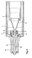
- gears are fixed non-rotatably on the second setting shafts when the gears are in engagement with an internal toothing of the second adjusting eccentric and when the second adjusting eccentric are rotatable by the gears in the circumferential direction.
- the second adjustment eccentric can be mounted in the first adjustment eccentric on a plain bearing, since no particularly frequent and large relative rotations are needed.
- the Space requirement in the radial direction in a plain bearing very low, which makes it possible to make the actual support bearing of the inner shell correspondingly large and robust. Nevertheless, with a plain bearing for a sprocket translation sufficiently high accuracy of the guide can be achieved in the radial direction.
- the roll shells may be made of any material used, for example of metal, in particular steel or a fiber composite material. They are expedient, viewed in the transverse direction, constructed symmetrically and have expedient in the roll center a greater hardness than at the ends, wherein the different hardnesses merge into one another evenly.
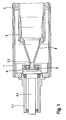
- Fig. 1 a design in which only a single adjustment eccentric is provided at the ends of the bending roller assembly.
- Fig. 2 a design in which two interposed adjusting eccentric are provided at the ends of the bending roller assembly.
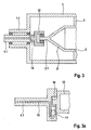
- Fig. 3 and Fig. 3a show a design in which a motor drive unit is provided for a radial displacement of the inner shell.
- Fig. 1 shown design shows one end of a bending roll assembly, comprising an outer shell 1 and an inner shell 2 made of steel, wherein on the outer shell 1, a reinforcement made of fiber-reinforced synthetic resin or a Schlmony harsh rubber is applied.
- the outer sheath can also consist entirely of fiber-reinforced synthetic resin.
- the outer shell is supported in the middle region of its longitudinal extension by an annular support body 3 in the radial direction on the inner shell non-rotatably, here on an elastic rubber ring.
- the outer casing 1 and the inner casing 2 are rotatable together and rotatably supported at both ends on mutually independent, end-side bearing journals 1.1, 2.1.
- the two-sided bearing pin 2.1 of the inner shell 2 thereby form the ends of hollow conical bells which are non-rotatably connected to the ends of the inner shell 2.
- the inner shell 2 can be shortened to the length of the supporting body 3 and be connected by the immediately adjacent bells 9 with the bearing pin 2.1. As a result, a particularly stiff, static training and support of the inner shell 2 is achieved. Overall, the inner shell 2 is always made considerably more rigid than the outer shell 1, in order to achieve that the outer shell 1 can be supported in the central region permanently on the inner shell 2 in order to set the desired deflection of the central region of the outer shell 1 targeted and permanent ,
- first adjusting eccentric 4 are provided with a respective eccentric to the first bearing pin 1.1 recorded support bearing 5 for the bearing journals 2.1 of the inner shell and that for a relative rotation of the first adjustment eccentric 4 in the circumferential direction in each case a bearing pin 1.1 centric outwardly penetrating, first adjustment shaft 4.1 is provided.
- the arrangement is made consistent in the region of both ends of the bending roller assembly.
- the size of the eccentricity of the first setting eccentric 4 is rigidly fixed in this design to a fixed value, wherein the direction of the eccentricity, based on the circumferential direction, is determined by the respective position of the first adjustment shafts 4.1.
- Fig. 1 shows the deflection of the eccentricity in the leaf level upwards.
- the direction of the deflection is dependent on the position of the adjustment shaft 4.1 and is maintained at circulating bending roller assembly. It can be displaced out of the plane of the drawing by relative turning of the first adjusting shaft 4.1.
- the deflection of the bending roller arrangement which reaches its maximum value in the central region of the longitudinal extent and is denoted by D, can be used to produce a extend parallel to the page level from bottom to top over the roller assembly running, flexible web in the transverse direction.
- the degree of stretching depends largely on the magnitude of the eccentricity of the first adjustment eccentric 4, the diameter of the outer shell 1, and the grip and type of surface coating of the outer shell 1. Particularly good values are achieved using surface coatings of soft rubber.
- the eccentricity of the first adjustment eccentric is rigidly fixed and not changeable during normal use. It is only possible to rotate the adjusting shaft 4.1 about its axis so that the maximum value of the eccentricity in a deviating from the direction of the web or sheet level direction, with the result that parallel to the direction of the web a correspondingly reduced effect in Transverse direction results. In this case, however, depending on the relative rotation of the first adjustment shafts 4.1, secondary deflections in other directions must be accepted, which are often undesirable or technically disturbing.
- the size of the deflection in the middle range depends solely on the eccentricity of the setting eccentric and can be easily adjusted to almost any size. Only the durability of the outer sheath rotating during the intended use sets limits to these values.
- Fig. 3 and Fig. 3a show a design in longitudinal and cross-sectional view, in which for a radial displacement of the inner shell 2, a motor drive unit is provided, which is enclosed by the outer shell 1. It is effective parallel to the longitudinal direction of a guide 10, which extends transversely to the longitudinal axis and the drawing plane of the bending roller assembly and consists of a piston / cylinder unit 11 which is included in the adjustment shaft 4.1 and can be acted upon by a hydraulic fluid.
- the bearing 12 of the inner shell 2 can thereby be moved parallel to the longitudinal direction of the guide 10 and transversely to the outer shell 1.
Landscapes
- Engineering & Computer Science (AREA)
- General Engineering & Computer Science (AREA)
- Mechanical Engineering (AREA)
- Paper (AREA)
- Rolls And Other Rotary Bodies (AREA)
Abstract
Description
- Die Erfindung betrifft eine Biegewalzenanordnung, umfassend einen Außenmantel und einen Innenmantel, die im mittleren Bereich ihrer Längserstreckung durch einen Abstützkörper in radialer Richtung aufeinander abgestützt, gemeinsam rotierbar und auf voneinander unabhängigen, stirnseitigen Lagerzapfengelagert sind, wobei Mittel vorgesehen sind, die es gestatten, die Lagerzapfen des Innenmantels relativ zu den Lagerzapfen des Außenmantels in radialer Richtung zu verschieben.
- Eine solche Biegewalzenanordnung ist aus der
DE 10 2004 045 407 A1 bekannt. Der Außen- und der Innenmantel sind dabei im mittleren Bereich ihrer Längserstreckung mittels eines Ringvorsprunges aufeinander abgestützt, im übrigen durch einen Spalt von einander getrennt und an den stirnseitigen Enden unabhängig voneinander gelagert und mittels der Lager positionsverstellbar in Stützkonstruktionen abgestützt. Dies ermöglicht es, die Enden gegeneinander in radialer Richtung zu verschieben, um eine mittige, definierte Durchbiegung des Außenmantels einzustellen und die Biegewalze z.B. in einem Breitstreckwerk zu verwenden, um eine darüber laufende, flexible Warenbahn in Querrichtung zu strecken. Die Größe der Durchbiegung des Außenmantels und das Anwendungsspektrum solcher Biegewalzen sind allerdings begrenzt. Es entstand daher der Wunsch größere Werte der Durchbiegung einstellen zu können. Das Einstellen einer bestimmten Durchbiegung ist außerdem mit erheblichem Aufwand verbunden und dadurch wenig befriedigend. Eine andere Anwendung bezieht sich darauf, eine zusätzliche Abstützung im mittleren Bereich einer auf Biegung beanspruchten Walze zur Verfügung zu haben, um das Auftreten einer Durchbiegung zu verhindern bzw. zu kompensieren. Derartige Anwendungen ergeben sich z.B. bei Andrückrollen, die beim Aufwickeln flexibler Warenbahnen zur Anwendung gelangen können. - Der Erfindung liegt die Aufgabe zu Grunde, eine solche Vorrichtung derart weiter zu entwickeln, dass bei vereinfachter Einstellbarkeit der Durchbiegung größerer Werte für die Durchbiegungen oder die Kompensation von Durchbiegungen erhalten werden können.
- Diese Aufgabe wird erfindungsgemäß bei einer Biegewalzenanordnung nach dem Oberbegriff durch die kennzeichnenden Merkmale von Anspruch 1 gelöst. Auf vorteilhafte Weiterbildungen nehmen die Unteransprüche Bezug.
- Bei der erfindungsgemäßen Biegewalzenanordnung ist es demgemäss vorgesehen, dass , dass die Mittel von dem Außenmantel radial umschlossen sind und zumindest eine erste Verstelleinrichtung für die radiale Verschiebung der Lagerzapfen des Innenmantels umfassen. Die Lagerzapfen des Außen- und des Innenmantels sind jeweils mit dem Außen- bzw. Innenmantel unverdrehbar verbunden, beispielsweise durch Flansche, und im Normalfall auf auf Wälz- oder Gleitlagern in einer Stützkonstruktion gelagert.
- Durch die Anbringung der eine radiale Verschiebung der Achse des Innenmantels bewirkenden Mittel im Inneren des Außenmantels gelangen sie an einer statisch günstigeren Stelle als bisher zum Einsatz und sind daher wirkungsvoller als bisher gestaltbar. Außerdem erfordert die Montage keine besonderen Maßnahmen oder Hilfsmitel an äußeren oder sekundären Stützkontruktionen, sondern die Biegewalzenanordnung kann als in sich geschlossene Bauheinheit im Falle einer Beschädigung einfacher ausgetauscht werden als bisher.
- Nach einer vorteilhaften Ausgestaltung ist es vorgesehen, dass der oder die in radialer Richtung wirksame Verstelleinrichtung mechanisch und/oder motorisch verstellbar ist bzw. sind. Falls an den beiden einander gegenüberliegenden Enden des Innenmantels Verstelleinrichtungen vorgesehen sind, gelangen diese paaarweise zur Anwendung mit der zweckmäßigen Maßgabe, dass eine parallele Verstellung beider Verstelleinrichtungen vorgesehen ist, um eine symmetrische Abstützwirkung des Außenmantels zu erzielen. Natürlich ist es bei entsprechendem Bedarf auch möglich eine unsymmetrische Verstellung vorzunehmen und die Verstelleinrichtungen zu diesem Zweck unsymmetrisch zu verstellen.
- Die Einstellexzenter können motorisch verstellbar ausgebildet sein und eine elektrisch, hydraulisch oder pneumatisch betätigbare Antriebseinheit umfassen. Das Einstellen gestatlet sich bei einer solchen Ausführung ganz besonders einfach.
- Die erste Verstelleinrichtung kann zumindest eine Keilverstellung oder zumindest einen Einstellexzenter umfassen.
- Nach einer weiteren Ausgestaltung ist es vorgesehen, dass an den beiden Enden des Innenmantels erste Einstellexzenter mit jeweils einem exzentrisch zu den ersten Lagerzapfen aufgenommenen Stützlager für die Lagerzapfen des Innenmantels vorgesehen sind und dass die ersten Einstellexzenter Bestandteile von die Lagerzapfen zentrisch nach außen durchdringenden, ersten Einstellwellen bilden, die in Umfangsrichtung verdrehbar sind. Die Exzentrizität hat bei dieser Bauform einen starren Wert und ist durch eine Relativverdrehung der ersten Einstellwelle an jede beliebige Umfangsstelle verlagerbar. In den meisten Anwendungsfällen kommt es darauf an, dass eine definierte Durchbiegung der Biegewalze nur in einer bestimmten Richtung vorhanden ist und dass sekundäre Auslenkungen in anderen Richtungen in Kauf genommen werden können. Dieser Forderung lässt sich mit einer solch einfachen Bauform mit hinreichender Genauigkeit entsprechen, wobei die Einfachheit der Einstellung der Durchbiegung in einer definierten Richtung von besonderer Bedeutung ist. Die jeweils gewünschte Größe der Durchbiegung in dieser Richtung kann durch einfaches Verdrehen der ersten Einstellwelle zwischen dem minimalen und dem maximalen Wert eingestellt und verändert werden. Der maximale Wert der Auslenkung wird im mittleren Bereich der Längserstreckung erzielt.
- Für Anwendungsfälle, in denen sekundäre Auslenkungen der Biegewalzenanordnung in anderen Richtungen nicht in Kauf genommen werden können, hat es sich bei einer solchen Bauform bewährt, wenn zwischen den Stützlagern des Innenmantels und dem ersten Einstellexzenter jeweils ein in Umfangsrichtung verdrehbarer, zweiter Einstellexzenter vorgesehen ist und wenn die zweiten Einstellexzenter durch zweite Einstellwellen verdrehbar sind, die die ersten Einstellwellen zentrisch nach außen durchdringen. Die Biegewirksamkeiten des ersten und des zweiten Einstellexzenters überlagern sich dabei gegenseitig derart, dass die radiale Durchbiegung des Außenmantels auf eine einzige Umfangsrichtung konzentriert ist und an dieser Umfangsstelle durch gezielte Relativverdrehungen des ersten und des zweiten Einstellexzenters auf irgend einen benötigten Zwischenwert zwischen der Minimal- und der Maximalauslenkung der Biegewalze eingestellt werden kann. Das Anwendungsspektrum der Biegewalze ist dadurch erheblich erweitert, wobei sich der zusätzliche Vorteil ergibt, dass die Biegewalze bei Durchbiegungen des Außenmantels, die unterhalb des Maximalwertes liegen, in mechanischer Hinsicht entsprechend weniger belastet wird. Die Dauerhaltbarkeit wird dadurch unter Umständen erheblich verbessert und es ergibt sich ferner die Möglichkeit, während der Veränderung der Umlaufgeschwindigkeit der Beigewalze Resonanzfrequenzen zu vermeiden, indem die Exzentrizitäten geringfügig verstellt werden.
- Dabei hat es sich als besonders vorteilhaft erwiesen, wenn auf den zweiten Einstellwellen Zahnräder unverdrehbar festgelegt sind, wenn die Zahnräder mit einer Innenverzahnung der zweiten Einstellexzenter in Eingriff stehen und wenn die zweiten Einstellexzenter durch die Zahnräder in Umfangsrichtung verdrehbar sind. Die zweiten Einstellexzenter können in dem ersten Einstellexzenter auf einem Gleitlager gelagert sein, da keine besonders häufigen und großen Relativverdrehungen benötigt werden. Außerdem ist der Platzbedarf in Radialer Richtung bei einem Gleitlager ganz besonders gering, was es gestattet, das eigentliche Traglager des Innenmantels entsprechend groß und robust zu gestalten. Dennoch kann mit einem Gleitlager eine für eine Zahnkranzübersetzung hinreichend große Genauigkeit der Führung in radialer Richtung erreicht werden.
- Die Walzenmäntel können aus irgend einem einschlägig benutzten Werkstoff bestehen, beispielweise aus Metall, insbesondere aus Stahl oder einem Faserverbundstoff. Sie sind zweckmäßig, in Querrichtung betrachtet, symmetrisch aufgebaut und haben zweckmäßig in der Walzenmitte eine größere Härte als an den Enden, wobei die verschiedenen Härten gleichmäßig ineinander übergehen.
- Zwei beispielhafte Ausführungen der Erfindung sind in der beiliegenden Zeichnung hälftig und in Längsrichtung zum Teil aufgeschnitten dargestellt. Sie werden nachfolgend näher erläutert.
-
Fig. 1 eine Bauform, bei der an den Enden der Biegewalzenanordnung jeweils nur ein einziger Einstellexzenter vorgesehen ist. -
Fig. 2 eine Bauform, bei der an den Enden der Biegewalzenanordnung jeweils zwei ineinander gelagerte Einstellexzenter vorgesehen sind. -
Fig. 3 und Fig. 3a zeigen eine Bauform, bei der für eine radiale Verschiebung des Innenmantels eine motorische Antriebseinheit vorgesehen ist. - Die in
Fig. 1 gezeigte Bauform zeigt ein Ende einer Biegewalzenanordnung, umfassend einen Außenmantel 1 und einen Innenmantel 2 aus Stahl, wobei auf dem Außenmantel 1 eine Armierung aus faserverstärktem Kunstharz oder eine Schleißschicht aus Gummi aufgebracht ist. Der Außenmantel kann auch insgesamt aus faserverstärktem Kunstharz bestehen. Der Außenmantel ist im mittleren Bereich seiner Längserstreckung durch einen ringförmigen Abstützkörper 3 in radialer Richtung auf dem Innenmantel unverdrehbar abgestützt, hier auf einem elastischen Gummiring. Statt dessen kann auch ein unnachgiebiger, metallischer Ring zur Anwendung gelangen, eine Vielzahl von gleichmäßig in Umfangsrichtung verteilten, unnachgiebigen oder elastischen Stützkörpern oder ein Ringvorsprung des Innen - oder Außenmantels. Der Außenmantel 1 und der Innenmantel 2 sind gemeinsam rotierbar und an beiden Enden auf voneinander unabhängigen, stirnseitigen Lagerzapfen 1.1, 2.1 verdrehbar gelagert. Die beidseitigen Lagerzapfen 2.1 des Innenmantels 2 bilden dabei die Enden von hohlkegeligen Glocken, die unverdrehbar mit den Enden des Innenmantels 2 verbunden sind. - Der Innenmantel 2 kann bis auf die Länge des Abstützkörpers 3 verkürzt und durch die sich unmittelbar anschließenden Glocken 9 mit den Lagerzapfen 2.1 verbunden sein. Hierdurch wird eine besonders steife, statische Ausbildung und Abstützung des Innenmantels 2 erreicht. Insgesamt ist der Innenmantel 2 stets erheblich biegesteifer gestaltet als der Außenmantel 1, um zu erreichen, dass der Außenmantel 1 im mittleren Bereich dauerhaft auf dem Innenmantel 2 abgestützt werden kann, um die gewünschte Auslenkung des mittleren Bereichs des Außenmantels 1 gezielt und dauerhaft einstellen zu können.
- Zur Auslenkung des mittleren Bereichs des Außenmantels 1 sind an beiden Enden des Innenmantels 2 Mittel vorgesehen, die es gestatten, seine Lagerzapfen 2.1 parallel zu einander und relativ zu den Lagerzapfen 1.1 des Außenmantels 1 in einer radialen Richtung zu verschieben.
- Dazu ist es gemäß
Fig. 1 vorgesehen, dass in den ersten Lagerzapfen 1.1 des Außenmantels erste Einstellexzenter 4 mit jeweils einem exzentrisch zu den ersten Lagerzapfen 1.1 aufgenommenen Stützlager 5 für die Lagerzapfen 2.1 des Innenmantels vorgesehen sind und dass für eine Relativverdrehung der ersten Einstellexzenter 4 in Umfangsrichtung jeweils eine die Lagerzapfen 1.1 zentrisch nach außen durchdringende, erste Einstellwelle 4.1 vorgesehen ist. Die Anordnung ist im Bereich von beiden Enden der Biegewalzenanordnung übereinstimmend gestaltet. - Die Größe der Exzentriziät des ersten Einstellexenters 4 ist bei dieser Bauform auf einen festen Wert starr festgelegt, wobei die Richtung der Exzentrizität, bezogen auf die Umfangsrichtung, durch die jeweiligen Stellung der ersten Einstellwellen 4.1 bestimmt ist. In der Darstellung gemäß
Fig. 1 zeigt die Auslenkung der Exzentrizität in der Blattebene nach oben. Am oberen Ende der Biegewalzenanordnung ergibt sich als Folge davon eine stärkere Komprimierung des ringförmigen Stützkörpers 3 als am unteren Ende, zugleich aber auch durchgehend eine konvexe Durchbiegung und Auslenkung des Außenmantels 1, die vor allem im mittleren Bereich seiner Längserstreckung deutlich in Erscheinung tritt. Die Richtung der Durchbiegung ist von der Stellung der Einstellwelle 4.1 abhängig und bleibt bei umlaufender Biegewalzenanordnung erhalten. Sie kann durch Relativverdrehen der ersten Einstellwelle 4.1 aus der Ebene der Zeichnung heraus verlagert werden. - Bei dem in
Fig. 1 gezeigten Ausführungsbeispiel kann die Auslenkung der Biegewalzenanordnung, die ihren Maximalwert im mittleren Bereich der Längserstreckung erzielt und mit D bezeichnet ist, dazu benutzt werden, eine parallel zur Blattebene von unten nach oben über die Walzenanordnung laufende, flexible Warenbahn in Querrichtung zu strecken. - Der Grad der Streckung hängt maßgeblich von der Größe der Exzentriziät des ersten Einstellexzenters 4 ab, vom Durchmesser des Außenmantels 1 sowie von der Griffigkeit und Art der Oberflächenbeschichtung des Außenmantels 1. Besonders gute Werte werden unter Verwendung von Oberflächenbeschichtungen aus Weichgummi erzielt.
- Bei der Bauform nach
Fig. 1 ist die Exzentrizität des ersten Einstellexzenters starr festgelegt und während der bestimmungsgemäßen Verwendung nicht veränderbar. Es ist lediglich möglich, die Einstellwelle 4.1 so um ihre Achse zu verdrehen, dass der Maximalwert der Exzentrizität in eine von der Laufrichtung der Warenbahn bzw. Blattebene abweichende Richtung zeigt, mit der Folge, dass sich parallel zur Laufrichtung der Warenbahn eine entsprechend reduzierte Wirkung in Querrichtung ergibt. Dabei müssen aber in Abhängigkeit von der jeweiligen Relativerdrehung der ersten Einstellwellen 4.1 Sekundärauslenkungen in anderen Richtungen in Kauf genommen werden, die häufig nicht erwünscht oder technisch störend sind. - Diese Probleme werden bei der Bauform nach
Fig. 2 überwunden, bei der es vorgesehen ist, dass zwischen den Stützlagern 5 und den ersten Einstellexzentern 4 jeweils ein in Umfangsrichtung relativ verdrehbarer, zweiter Einstellexzenter 6 vorgesehen ist, wobei die zweiten Einstellexzenter 6 durch zweite Einstellwellen 8.1 relativ verdrehbar sind, die die ersten Einstellwellen 4.1 zentrisch nach außen durchdringen. Die Größe der Exzentrizität des Außenmantels 1 im mittleren Bereich ergibt sich dadurch als Resultierende aus den beiden gegeneinander verdrehbaren Exzentrizitäten der ersten und zweiten Einstellexzenter 4, 6 in Bezug zu einander. Sie kann daher bei dieser Bauform zwischen dem Wert Null und dem Maximalwert stufenlos verändert und außerdem auf eine bestimmte Richtung konzentriert werden. Die technische Verwendbarkeit dadurch wesentlich verbessert. Außerdem ist es in vielen Fällen nicht erforderlich, mit der maximalen Durchbiegung bzw. Auslenkung des Außenmantels 1 im mittleren Bereich seiner Längserstreckung zu arbeiten. Die mechanische Beanspruchung des zu seiner Herstellung verwendeten Werkstoffes lässt sich wird dadurch erheblich vermindern und die Dauerhaltbarkeit entsprechend verbessern. - Als vorteilhaft hat es sich bewährt, wenn bei einer solchen Bauform auf den zweiten Einstellwellen 8.1 Zahnräder 8 unverdrehbar festgelegt sind, wenn die Zahnräder 8 mit einer Innenverzahnung 7 der zweiten Einstellexzenter 6 in Eingriff stehen und wenn die zweiten Einstellexzenter 6 durch die Zahnräder 8 in Umfangsrichtung verdrehbar sind. Eine solche Konstruktion zeichnet sich durch eine besonders große Robustheit und Langlebigkeit aus. Sie bedarf so gut wie keiner Wartung. Außerdem ist es von besonderem Vorteil, dass die jeweilige Stellung der Einstellexzenter 4,6 von außen erkennbar und in Bezug auf die jeweilige Stellung der beiden Einstellwellen 4.1, 8.1 unveränderlich ist. Die Einstellung exakt definierter Durchbiegungen für bestimmte Anwendungsfälle wird dadurch wesentlich vereinfacht.
- Die Größe der Durchbiegung im mittleren Bereich ist allein von der Exzentriziät der Einstellexzenter abhängig und kann einfach und auf nahezu beliebig große Werte eingestellt werden. Allein die Dauerhaltbarkeit des während der bestimmungsgemäßen Verwendung rotierenden Außenmantels setzt diesen Werten Grenzen.
-
Fig. 3 und Fig. 3a zeigen eine Bauform in längs- und quergeschnittener Darstellung, bei der für eine radiale Verschiebung des Innenmantels 2 eine motorische Antriebseinheit vorgesehen ist, die von dem Außenmantel 1 umschlossen ist. Sie ist parallel zur Längsrichtung einer Führung 10 wirksam, die sich quer zur Längsachse und der Zeichungsbene der Biegewalzenanordnung erstreckt und aus einer Kolben-/Zylindereinheit 11 besteht, welche in der Einstellwelle 4.1 enthalten und mit einer hydraulischen Flüssigkeit beaufschlagbar ist. Die Lagerung 12 des Innenmantels 2 läßt sich hierdurch parallel zur Längsrichtung der Führung 10 und quer zum Außenmantel 1 verschieben. Für die Zuleitung der hydraulsichen Flüssigkeit sind Kanäle 13 vorgehen, die in der Einstellwelle 4.1 aufgenommen sind und die deren Stirnfläche mit dem Zylinder der Kolben-/Zylindereinheit verbinden. Der Kolben ist in üblicher Weise durch Topfdichtungen gegenüber der Zylinderwandung abgedichtet. Der ringförmige Abstützkörper besteht bei dieser Bauform aus vergütetem Stahl. Ein socher Werkstoff ist frei von Relaxationserscheinungen, was es erlaubt, die Exzentrizität des Außenmantels feinfühlig und dauerhaft auf sehr exakte Werte einzustellen.
Claims (7)
- Biegewalzenanordnung, umfassend einen Außenmantel (1) und einen Innenmantel (2), die im mittleren Bereich ihrer Längserstreckung durch mindestens einen Abstützkörper (3) in radialer Richtung aufeinander abgestützt, gemeinsam rotierbar und auf voneinander unabhängigen, stirnseitigen Lagerzapfen (1.1, 2.1) gelagert sind, wobei Mittel vorgesehen sind, die es gestatten, die Lagerzapfen (2.1) des Innenmantels (2) relativ zu den Lagerzapfen (1.1) des Außenmantels (1) in radialer Richtung zu verschieben, dadurch gekennzeichnet, dass die Mittel von dem Außenmantel (1) radial umschlossen sind und zumindest eine erste Verstelleinrichtung (9) für die radiale Verschiebung der Lagerzapfen (2.1) des Innenmantels (2) umfassen.
- Biegewalzenanordnung nach Anspruch 1, dadurch gekennzeichnet, dass der erste Verstelleinrichtung (9) mechanisch und/oder motorisch verstellbar ist.
- Biegewalzenanordnung nach Anspruch 1, bei der der erste Verstelleinrichtung (9) motorisch verstellbar ist, dadurch gekennzeichnet, dass die motorische Verstellung eine elektrisch, hydraulisch oder pneumatisch betätigbare Antriebseinheit umfasst.
- Biegewalzenanordnung nach einem der Ansprüche 1 bis 3, dadurch gekennzeichnet, dass die erste Verstelleinrichtung (9) zumindest eine Keilverstellung oder zumindest einen Einstellexzenter umfasst.
- Biegewalzenanordnung nach Anspruch 4, bei der die Verstelleinrichtung zumindest einen ersten Einstellexzenter umfasst, dadurch gekennzeichnet, dass an den beiden Enden des Innenmantels (2) erste Einstellexzenter (4) mit einem exzentrisch zu den ersten Lagerzapfen (1.1) aufgenommenen Stützlager (5) für die Lagerzapfen (2.1) des Innenmantels vorgesehen sind und dass die ersten Einstellexzenter Bestandteile von die Lagerzapfen (1.1) zentrisch nach außen durchdringenden, ersten Einstellwellen (4.1) bilden, die in Umfangsrichtung verdrehbar sind.
- Biegewalzenanordnung nach Anspruch 5, dadurch gekennzeichnet, dass zwischen den ersten Einstellexzentern (4) und den Stützlagern (5) jeweils ein in Umfangsrichtung verdrehbarer, zweiter Einstellexzenter (6) vorgesehen ist und dass die zweiten Einstellexzenter (6) durch zweite Einstellwellen (8.1) verdrehbar sind, die die ersten Einstellwellen (4.1) zentrisch nach außen durchdringen.
- Biegewalzenanordnung nach Anspruch 6, dadurch gekennzeichnet, dass auf den zweiten Einstellwellen (8.1) Zahnräder (8) unverdrehbar festgelegt sind, dass die Zahnräder (8) mit einer Innenverzahnung (7) der zweiten Einstellexzenter (6) in Eingriff stehen und dass die zweiten Einstellexzenter (6) durch die Zahnräder (8) in Umfangsrichtung verdrehbar sind.
Applications Claiming Priority (1)
| Application Number | Priority Date | Filing Date | Title |
|---|---|---|---|
| DE200610057907 DE102006057907B4 (de) | 2006-12-08 | 2006-12-08 | Biegewalzenanordnung |
Publications (3)
| Publication Number | Publication Date |
|---|---|
| EP1988212A2 true EP1988212A2 (de) | 2008-11-05 |
| EP1988212A3 EP1988212A3 (de) | 2011-10-26 |
| EP1988212B1 EP1988212B1 (de) | 2015-04-15 |
Family
ID=39365472
Family Applications (1)
| Application Number | Title | Priority Date | Filing Date |
|---|---|---|---|
| EP20070023641 Not-in-force EP1988212B1 (de) | 2006-12-08 | 2007-12-06 | Biegewalzenanordnung |
Country Status (2)
| Country | Link |
|---|---|
| EP (1) | EP1988212B1 (de) |
| DE (1) | DE102006057907B4 (de) |
Cited By (1)
| Publication number | Priority date | Publication date | Assignee | Title |
|---|---|---|---|---|
| WO2013075883A1 (de) * | 2011-11-23 | 2013-05-30 | Voith Patent Gmbh | Breitstreckwalze |
Families Citing this family (1)
| Publication number | Priority date | Publication date | Assignee | Title |
|---|---|---|---|---|
| JP6148418B1 (ja) * | 2016-02-24 | 2017-06-14 | 日本タングステン株式会社 | ロータリーカッター用ロールおよびロータリーカッター |
Citations (1)
| Publication number | Priority date | Publication date | Assignee | Title |
|---|---|---|---|---|
| DE102004045407A1 (de) | 2003-09-26 | 2005-04-28 | Metso Paper Inc | Anlage zum Stützen einer Walze einer Papier-, Karton- oder Ausrüstungsmaschine und Verfahren zur Steuerung der Walzendurchbiegung |
Family Cites Families (8)
| Publication number | Priority date | Publication date | Assignee | Title |
|---|---|---|---|---|
| DE211326C (de) * | ||||
| FI50896C (fi) * | 1969-06-04 | 1976-08-10 | Ahlstroem Oy | Tela |
| FI57471C (fi) * | 1976-01-21 | 1980-08-11 | Ahlstroem Oy | Vals med reglerbar nedboejning |
| DE2823089A1 (de) * | 1978-05-26 | 1979-11-29 | Jagdfeld Heinz Josef Dipl Ing | Walze, insbesondere kalanderwalze |
| DE2832457A1 (de) * | 1978-07-24 | 1980-02-14 | Koller Rudolf | Walzenpaar zum auswalzen plastischer werkstoffe und zum bearbeiten von bahnfoermigen produkten |
| DE2940879A1 (de) * | 1979-10-09 | 1981-04-23 | M.A.N.- Roland Druckmaschinen AG, 6050 Offenbach | Vorrichtung zum biegen einer druckwalze in einer rotationsdruckmaschine |
| DE19945156B4 (de) * | 1999-09-21 | 2009-05-20 | Voith Patent Gmbh | Walze |
| DE102005044957A1 (de) * | 2005-09-20 | 2007-03-22 | Voith Patent Gmbh | Breitstreckwalze |
-
2006
- 2006-12-08 DE DE200610057907 patent/DE102006057907B4/de not_active Expired - Fee Related
-
2007
- 2007-12-06 EP EP20070023641 patent/EP1988212B1/de not_active Not-in-force
Patent Citations (1)
| Publication number | Priority date | Publication date | Assignee | Title |
|---|---|---|---|---|
| DE102004045407A1 (de) | 2003-09-26 | 2005-04-28 | Metso Paper Inc | Anlage zum Stützen einer Walze einer Papier-, Karton- oder Ausrüstungsmaschine und Verfahren zur Steuerung der Walzendurchbiegung |
Cited By (1)
| Publication number | Priority date | Publication date | Assignee | Title |
|---|---|---|---|---|
| WO2013075883A1 (de) * | 2011-11-23 | 2013-05-30 | Voith Patent Gmbh | Breitstreckwalze |
Also Published As
| Publication number | Publication date |
|---|---|
| EP1988212B1 (de) | 2015-04-15 |
| DE102006057907A1 (de) | 2008-06-19 |
| DE102006057907B4 (de) | 2008-10-23 |
| EP1988212A3 (de) | 2011-10-26 |
Similar Documents
| Publication | Publication Date | Title |
|---|---|---|
| DE4239411C1 (de) | ||
| DE3639009C2 (de) | ||
| DE3501635A1 (de) | Presswalze | |
| DE711527C (de) | Gleitlager | |
| DE2718734A1 (de) | Walze, insbesondere breitstreckwalze | |
| DE2646769A1 (de) | Presswalze mit durchbiegungskontrollvorrichtung | |
| DE19927897A1 (de) | Kontakt- oder Transportwalze mit einstellbarer Biegung | |
| DE69819562T2 (de) | Stützwalzenanordnung mit dynamischer balligkeitsregelung | |
| EP0295449A2 (de) | Vorrichtung zum Bedrucken oder Stanzen einer Materialbahn | |
| WO1997028075A1 (de) | Walze für eine wickelmaschine | |
| DE69838504T2 (de) | Biegbare rolle für bandförmiges material | |
| DE3317457A1 (de) | Presseinrichtung fuer bandfoermiges gut, insbesondere zum entwaessern einer papierbahn | |
| DE102006049290B4 (de) | Walze mit einstellbarer Biegung | |
| DE2522657B2 (de) | Walze zur Druckbehandlung von bahnförmigen Materialien | |
| DE102012214830B4 (de) | Hydrostatische Axialkolbenmaschine mit verstellbarer Schrägscheibe oder Schenkwiege und zugehörigem Gleitlager mit hydrostatischem Druckfeld, dessen Randkonturausbildung den Leckagestrom ins Gehäuse minimiert | |
| DE4435845C1 (de) | Preßwalze | |
| DE102008016000B3 (de) | Walzenpresse | |
| EP1988212B1 (de) | Biegewalzenanordnung | |
| DE2832457A1 (de) | Walzenpaar zum auswalzen plastischer werkstoffe und zum bearbeiten von bahnfoermigen produkten | |
| DE10305511B9 (de) | Walze | |
| DE4026007C2 (de) | Durchbiegungseinstellwalze | |
| EP0741253B1 (de) | Presswalze und Maschine mit Presswalze | |
| EP1114890A2 (de) | Walzenanordnung und Walze | |
| EP0203279B1 (de) | Walze, vorzugsweise Gegendruckwalze eines Tiefdruckformzylinders, mit durchbiegbarem Walzenmantel | |
| EP0962668B1 (de) | Druckbehandlungswalze |
Legal Events
| Date | Code | Title | Description |
|---|---|---|---|
| PUAI | Public reference made under article 153(3) epc to a published international application that has entered the european phase |
Free format text: ORIGINAL CODE: 0009012 |
|
| AK | Designated contracting states |
Kind code of ref document: A2 Designated state(s): AT BE BG CH CY CZ DE DK EE ES FI FR GB GR HU IE IS IT LI LT LU LV MC MT NL PL PT RO SE SI SK TR |
|
| AX | Request for extension of the european patent |
Extension state: AL BA HR MK RS |
|
| PUAL | Search report despatched |
Free format text: ORIGINAL CODE: 0009013 |
|
| AK | Designated contracting states |
Kind code of ref document: A3 Designated state(s): AT BE BG CH CY CZ DE DK EE ES FI FR GB GR HU IE IS IT LI LT LU LV MC MT NL PL PT RO SE SI SK TR |
|
| AX | Request for extension of the european patent |
Extension state: AL BA HR MK RS |
|
| RIC1 | Information provided on ipc code assigned before grant |
Ipc: B65H 23/025 20060101ALI20110920BHEP Ipc: F16C 13/02 20060101ALI20110920BHEP Ipc: F16C 13/00 20060101ALI20110920BHEP Ipc: D21G 1/00 20060101ALI20110920BHEP Ipc: D21F 1/40 20060101ALI20110920BHEP Ipc: D21G 1/02 20060101AFI20110920BHEP |
|
| 17P | Request for examination filed |
Effective date: 20120425 |
|
| AKX | Designation fees paid |
Designated state(s): AT BE BG CH CY CZ DE DK EE ES FI FR GB GR HU IE IS IT LI LT LU LV MC MT NL PL PT RO SE SI SK TR |
|
| 17Q | First examination report despatched |
Effective date: 20120803 |
|
| GRAP | Despatch of communication of intention to grant a patent |
Free format text: ORIGINAL CODE: EPIDOSNIGR1 |
|
| INTG | Intention to grant announced |
Effective date: 20141022 |
|
| GRAS | Grant fee paid |
Free format text: ORIGINAL CODE: EPIDOSNIGR3 |
|
| RAP1 | Party data changed (applicant data changed or rights of an application transferred) |
Owner name: INOMETA GMBH & CO. KG |
|
| GRAA | (expected) grant |
Free format text: ORIGINAL CODE: 0009210 |
|
| AK | Designated contracting states |
Kind code of ref document: B1 Designated state(s): AT BE BG CH CY CZ DE DK EE ES FI FR GB GR HU IE IS IT LI LT LU LV MC MT NL PL PT RO SE SI SK TR |
|
| REG | Reference to a national code |
Ref country code: GB Ref legal event code: FG4D Free format text: NOT ENGLISH Ref country code: CH Ref legal event code: EP |
|
| REG | Reference to a national code |
Ref country code: IE Ref legal event code: FG4D Free format text: LANGUAGE OF EP DOCUMENT: GERMAN |
|
| REG | Reference to a national code |
Ref country code: AT Ref legal event code: REF Ref document number: 722058 Country of ref document: AT Kind code of ref document: T Effective date: 20150515 |
|
| REG | Reference to a national code |
Ref country code: DE Ref legal event code: R096 Ref document number: 502007013867 Country of ref document: DE Effective date: 20150528 |
|
| REG | Reference to a national code |
Ref country code: NL Ref legal event code: VDEP Effective date: 20150415 |
|
| REG | Reference to a national code |
Ref country code: LT Ref legal event code: MG4D |
|
| PG25 | Lapsed in a contracting state [announced via postgrant information from national office to epo] |
Ref country code: NL Free format text: LAPSE BECAUSE OF FAILURE TO SUBMIT A TRANSLATION OF THE DESCRIPTION OR TO PAY THE FEE WITHIN THE PRESCRIBED TIME-LIMIT Effective date: 20150415 |
|
| PG25 | Lapsed in a contracting state [announced via postgrant information from national office to epo] |
Ref country code: ES Free format text: LAPSE BECAUSE OF FAILURE TO SUBMIT A TRANSLATION OF THE DESCRIPTION OR TO PAY THE FEE WITHIN THE PRESCRIBED TIME-LIMIT Effective date: 20150415 Ref country code: PT Free format text: LAPSE BECAUSE OF FAILURE TO SUBMIT A TRANSLATION OF THE DESCRIPTION OR TO PAY THE FEE WITHIN THE PRESCRIBED TIME-LIMIT Effective date: 20150817 Ref country code: LT Free format text: LAPSE BECAUSE OF FAILURE TO SUBMIT A TRANSLATION OF THE DESCRIPTION OR TO PAY THE FEE WITHIN THE PRESCRIBED TIME-LIMIT Effective date: 20150415 |
|
| PG25 | Lapsed in a contracting state [announced via postgrant information from national office to epo] |
Ref country code: IS Free format text: LAPSE BECAUSE OF FAILURE TO SUBMIT A TRANSLATION OF THE DESCRIPTION OR TO PAY THE FEE WITHIN THE PRESCRIBED TIME-LIMIT Effective date: 20150815 Ref country code: LV Free format text: LAPSE BECAUSE OF FAILURE TO SUBMIT A TRANSLATION OF THE DESCRIPTION OR TO PAY THE FEE WITHIN THE PRESCRIBED TIME-LIMIT Effective date: 20150415 Ref country code: GR Free format text: LAPSE BECAUSE OF FAILURE TO SUBMIT A TRANSLATION OF THE DESCRIPTION OR TO PAY THE FEE WITHIN THE PRESCRIBED TIME-LIMIT Effective date: 20150716 |
|
| REG | Reference to a national code |
Ref country code: DE Ref legal event code: R097 Ref document number: 502007013867 Country of ref document: DE |
|
| PG25 | Lapsed in a contracting state [announced via postgrant information from national office to epo] |
Ref country code: EE Free format text: LAPSE BECAUSE OF FAILURE TO SUBMIT A TRANSLATION OF THE DESCRIPTION OR TO PAY THE FEE WITHIN THE PRESCRIBED TIME-LIMIT Effective date: 20150415 Ref country code: DK Free format text: LAPSE BECAUSE OF FAILURE TO SUBMIT A TRANSLATION OF THE DESCRIPTION OR TO PAY THE FEE WITHIN THE PRESCRIBED TIME-LIMIT Effective date: 20150415 |
|
| PLBE | No opposition filed within time limit |
Free format text: ORIGINAL CODE: 0009261 |
|
| STAA | Information on the status of an ep patent application or granted ep patent |
Free format text: STATUS: NO OPPOSITION FILED WITHIN TIME LIMIT |
|
| PG25 | Lapsed in a contracting state [announced via postgrant information from national office to epo] |
Ref country code: SK Free format text: LAPSE BECAUSE OF FAILURE TO SUBMIT A TRANSLATION OF THE DESCRIPTION OR TO PAY THE FEE WITHIN THE PRESCRIBED TIME-LIMIT Effective date: 20150415 Ref country code: RO Free format text: LAPSE BECAUSE OF NON-PAYMENT OF DUE FEES Effective date: 20150415 Ref country code: CZ Free format text: LAPSE BECAUSE OF FAILURE TO SUBMIT A TRANSLATION OF THE DESCRIPTION OR TO PAY THE FEE WITHIN THE PRESCRIBED TIME-LIMIT Effective date: 20150415 Ref country code: PL Free format text: LAPSE BECAUSE OF FAILURE TO SUBMIT A TRANSLATION OF THE DESCRIPTION OR TO PAY THE FEE WITHIN THE PRESCRIBED TIME-LIMIT Effective date: 20150415 |
|
| 26N | No opposition filed |
Effective date: 20160118 |
|
| PG25 | Lapsed in a contracting state [announced via postgrant information from national office to epo] |
Ref country code: IT Free format text: LAPSE BECAUSE OF FAILURE TO SUBMIT A TRANSLATION OF THE DESCRIPTION OR TO PAY THE FEE WITHIN THE PRESCRIBED TIME-LIMIT Effective date: 20150415 |
|
| PG25 | Lapsed in a contracting state [announced via postgrant information from national office to epo] |
Ref country code: BE Free format text: LAPSE BECAUSE OF NON-PAYMENT OF DUE FEES Effective date: 20151231 Ref country code: SI Free format text: LAPSE BECAUSE OF FAILURE TO SUBMIT A TRANSLATION OF THE DESCRIPTION OR TO PAY THE FEE WITHIN THE PRESCRIBED TIME-LIMIT Effective date: 20150415 |
|
| PG25 | Lapsed in a contracting state [announced via postgrant information from national office to epo] |
Ref country code: LU Free format text: LAPSE BECAUSE OF FAILURE TO SUBMIT A TRANSLATION OF THE DESCRIPTION OR TO PAY THE FEE WITHIN THE PRESCRIBED TIME-LIMIT Effective date: 20151206 Ref country code: MC Free format text: LAPSE BECAUSE OF FAILURE TO SUBMIT A TRANSLATION OF THE DESCRIPTION OR TO PAY THE FEE WITHIN THE PRESCRIBED TIME-LIMIT Effective date: 20150415 |
|
| REG | Reference to a national code |
Ref country code: CH Ref legal event code: PL |
|
| GBPC | Gb: european patent ceased through non-payment of renewal fee |
Effective date: 20151206 |
|
| REG | Reference to a national code |
Ref country code: IE Ref legal event code: MM4A |
|
| REG | Reference to a national code |
Ref country code: FR Ref legal event code: ST Effective date: 20160831 |
|
| PG25 | Lapsed in a contracting state [announced via postgrant information from national office to epo] |
Ref country code: IE Free format text: LAPSE BECAUSE OF NON-PAYMENT OF DUE FEES Effective date: 20151206 Ref country code: GB Free format text: LAPSE BECAUSE OF NON-PAYMENT OF DUE FEES Effective date: 20151206 Ref country code: CH Free format text: LAPSE BECAUSE OF NON-PAYMENT OF DUE FEES Effective date: 20151231 Ref country code: LI Free format text: LAPSE BECAUSE OF NON-PAYMENT OF DUE FEES Effective date: 20151231 |
|
| PG25 | Lapsed in a contracting state [announced via postgrant information from national office to epo] |
Ref country code: FR Free format text: LAPSE BECAUSE OF NON-PAYMENT OF DUE FEES Effective date: 20151231 |
|
| PG25 | Lapsed in a contracting state [announced via postgrant information from national office to epo] |
Ref country code: BG Free format text: LAPSE BECAUSE OF FAILURE TO SUBMIT A TRANSLATION OF THE DESCRIPTION OR TO PAY THE FEE WITHIN THE PRESCRIBED TIME-LIMIT Effective date: 20150415 Ref country code: HU Free format text: LAPSE BECAUSE OF FAILURE TO SUBMIT A TRANSLATION OF THE DESCRIPTION OR TO PAY THE FEE WITHIN THE PRESCRIBED TIME-LIMIT; INVALID AB INITIO Effective date: 20071206 |
|
| PG25 | Lapsed in a contracting state [announced via postgrant information from national office to epo] |
Ref country code: CY Free format text: LAPSE BECAUSE OF FAILURE TO SUBMIT A TRANSLATION OF THE DESCRIPTION OR TO PAY THE FEE WITHIN THE PRESCRIBED TIME-LIMIT Effective date: 20150415 Ref country code: SE Free format text: LAPSE BECAUSE OF FAILURE TO SUBMIT A TRANSLATION OF THE DESCRIPTION OR TO PAY THE FEE WITHIN THE PRESCRIBED TIME-LIMIT Effective date: 20150415 |
|
| PG25 | Lapsed in a contracting state [announced via postgrant information from national office to epo] |
Ref country code: MT Free format text: LAPSE BECAUSE OF FAILURE TO SUBMIT A TRANSLATION OF THE DESCRIPTION OR TO PAY THE FEE WITHIN THE PRESCRIBED TIME-LIMIT Effective date: 20150415 Ref country code: TR Free format text: LAPSE BECAUSE OF FAILURE TO SUBMIT A TRANSLATION OF THE DESCRIPTION OR TO PAY THE FEE WITHIN THE PRESCRIBED TIME-LIMIT Effective date: 20150415 |
|
| PGFP | Annual fee paid to national office [announced via postgrant information from national office to epo] |
Ref country code: FI Payment date: 20191209 Year of fee payment: 13 |
|
| PGFP | Annual fee paid to national office [announced via postgrant information from national office to epo] |
Ref country code: AT Payment date: 20191209 Year of fee payment: 13 |
|
| PGFP | Annual fee paid to national office [announced via postgrant information from national office to epo] |
Ref country code: DE Payment date: 20200131 Year of fee payment: 13 |
|
| REG | Reference to a national code |
Ref country code: DE Ref legal event code: R119 Ref document number: 502007013867 Country of ref document: DE |
|
| REG | Reference to a national code |
Ref country code: FI Ref legal event code: MAE |
|
| PG25 | Lapsed in a contracting state [announced via postgrant information from national office to epo] |
Ref country code: FI Free format text: LAPSE BECAUSE OF NON-PAYMENT OF DUE FEES Effective date: 20201206 |
|
| REG | Reference to a national code |
Ref country code: AT Ref legal event code: MM01 Ref document number: 722058 Country of ref document: AT Kind code of ref document: T Effective date: 20201206 |
|
| PG25 | Lapsed in a contracting state [announced via postgrant information from national office to epo] |
Ref country code: AT Free format text: LAPSE BECAUSE OF NON-PAYMENT OF DUE FEES Effective date: 20201206 |
|
| PG25 | Lapsed in a contracting state [announced via postgrant information from national office to epo] |
Ref country code: DE Free format text: LAPSE BECAUSE OF NON-PAYMENT OF DUE FEES Effective date: 20210701 |