EP1987353B1 - Fluid transfer mechanism - Google Patents
Fluid transfer mechanism Download PDFInfo
- Publication number
- EP1987353B1 EP1987353B1 EP07705600A EP07705600A EP1987353B1 EP 1987353 B1 EP1987353 B1 EP 1987353B1 EP 07705600 A EP07705600 A EP 07705600A EP 07705600 A EP07705600 A EP 07705600A EP 1987353 B1 EP1987353 B1 EP 1987353B1
- Authority
- EP
- European Patent Office
- Prior art keywords
- chamber
- liquid
- opening
- barrier layer
- fluid pathway
- Prior art date
- Legal status (The legal status is an assumption and is not a legal conclusion. Google has not performed a legal analysis and makes no representation as to the accuracy of the status listed.)
- Not-in-force
Links
- 239000012530 fluid Substances 0.000 title claims abstract description 31
- 238000012546 transfer Methods 0.000 title claims description 37
- 230000007246 mechanism Effects 0.000 title description 8
- 239000007788 liquid Substances 0.000 claims abstract description 101
- 230000004888 barrier function Effects 0.000 claims abstract description 37
- 230000000977 initiatory effect Effects 0.000 claims abstract description 18
- 230000014759 maintenance of location Effects 0.000 claims abstract description 14
- 238000006243 chemical reaction Methods 0.000 claims description 100
- 238000001514 detection method Methods 0.000 claims description 67
- 238000000034 method Methods 0.000 claims description 31
- 238000003018 immunoassay Methods 0.000 claims description 4
- 230000037361 pathway Effects 0.000 claims 13
- 230000000694 effects Effects 0.000 claims 1
- 239000010410 layer Substances 0.000 description 111
- 239000000523 sample Substances 0.000 description 34
- 239000011148 porous material Substances 0.000 description 21
- 239000011324 bead Substances 0.000 description 18
- 239000003153 chemical reaction reagent Substances 0.000 description 16
- 238000009739 binding Methods 0.000 description 15
- 239000000853 adhesive Substances 0.000 description 12
- 230000001070 adhesive effect Effects 0.000 description 12
- WQZGKKKJIJFFOK-VFUOTHLCSA-N beta-D-glucose Chemical compound OC[C@H]1O[C@@H](O)[C@H](O)[C@@H](O)[C@@H]1O WQZGKKKJIJFFOK-VFUOTHLCSA-N 0.000 description 9
- WQZGKKKJIJFFOK-GASJEMHNSA-N Glucose Natural products OC[C@H]1OC(O)[C@H](O)[C@@H](O)[C@@H]1O WQZGKKKJIJFFOK-GASJEMHNSA-N 0.000 description 8
- 230000008901 benefit Effects 0.000 description 8
- 108010074051 C-Reactive Protein Proteins 0.000 description 7
- 102100032752 C-reactive protein Human genes 0.000 description 7
- 239000012491 analyte Substances 0.000 description 7
- 239000000758 substrate Substances 0.000 description 7
- 239000008103 glucose Substances 0.000 description 6
- 238000012360 testing method Methods 0.000 description 6
- 125000006850 spacer group Chemical group 0.000 description 5
- 108090000790 Enzymes Proteins 0.000 description 4
- 102000004190 Enzymes Human genes 0.000 description 4
- KDLHZDBZIXYQEI-UHFFFAOYSA-N Palladium Chemical compound [Pd] KDLHZDBZIXYQEI-UHFFFAOYSA-N 0.000 description 4
- 230000008859 change Effects 0.000 description 4
- 238000004519 manufacturing process Methods 0.000 description 4
- 230000008569 process Effects 0.000 description 4
- 238000009736 wetting Methods 0.000 description 4
- 239000012790 adhesive layer Substances 0.000 description 3
- YAGKRVSRTSUGEY-UHFFFAOYSA-N ferricyanide Chemical compound [Fe+3].N#[C-].N#[C-].N#[C-].N#[C-].N#[C-].N#[C-] YAGKRVSRTSUGEY-UHFFFAOYSA-N 0.000 description 3
- 229920000139 polyethylene terephthalate Polymers 0.000 description 3
- 238000004080 punching Methods 0.000 description 3
- 230000004044 response Effects 0.000 description 3
- 239000000243 solution Substances 0.000 description 3
- 229920002799 BoPET Polymers 0.000 description 2
- 108010050375 Glucose 1-Dehydrogenase Proteins 0.000 description 2
- 239000002390 adhesive tape Substances 0.000 description 2
- 239000011230 binding agent Substances 0.000 description 2
- 230000001419 dependent effect Effects 0.000 description 2
- 239000012799 electrically-conductive coating Substances 0.000 description 2
- 238000005429 filling process Methods 0.000 description 2
- 229910052763 palladium Inorganic materials 0.000 description 2
- 239000000126 substance Substances 0.000 description 2
- JKMHFZQWWAIEOD-UHFFFAOYSA-N 2-[4-(2-hydroxyethyl)piperazin-1-yl]ethanesulfonic acid Chemical compound OCC[NH+]1CCN(CCS([O-])(=O)=O)CC1 JKMHFZQWWAIEOD-UHFFFAOYSA-N 0.000 description 1
- 239000007995 HEPES buffer Substances 0.000 description 1
- WQZGKKKJIJFFOK-DVKNGEFBSA-N alpha-D-glucose Chemical compound OC[C@H]1O[C@H](O)[C@H](O)[C@@H](O)[C@@H]1O WQZGKKKJIJFFOK-DVKNGEFBSA-N 0.000 description 1
- 239000012298 atmosphere Substances 0.000 description 1
- 210000004369 blood Anatomy 0.000 description 1
- 239000008280 blood Substances 0.000 description 1
- 239000000872 buffer Substances 0.000 description 1
- 239000004020 conductor Substances 0.000 description 1
- 238000013461 design Methods 0.000 description 1
- 230000009977 dual effect Effects 0.000 description 1
- 238000000840 electrochemical analysis Methods 0.000 description 1
- 238000000835 electrochemical detection Methods 0.000 description 1
- PCHJSUWPFVWCPO-UHFFFAOYSA-N gold Chemical compound [Au] PCHJSUWPFVWCPO-UHFFFAOYSA-N 0.000 description 1
- 239000010931 gold Substances 0.000 description 1
- 229910052737 gold Inorganic materials 0.000 description 1
- 230000001939 inductive effect Effects 0.000 description 1
- 230000003993 interaction Effects 0.000 description 1
- 238000010030 laminating Methods 0.000 description 1
- 239000012939 laminating adhesive Substances 0.000 description 1
- 238000003698 laser cutting Methods 0.000 description 1
- 229910052751 metal Inorganic materials 0.000 description 1
- 239000002184 metal Substances 0.000 description 1
- 239000000203 mixture Substances 0.000 description 1
- 230000003287 optical effect Effects 0.000 description 1
- -1 potassium ferricyanide Chemical compound 0.000 description 1
- 238000011160 research Methods 0.000 description 1
- 238000007789 sealing Methods 0.000 description 1
- 210000002966 serum Anatomy 0.000 description 1
- 239000012085 test solution Substances 0.000 description 1
- 238000013022 venting Methods 0.000 description 1
- XLYOFNOQVPJJNP-UHFFFAOYSA-N water Substances O XLYOFNOQVPJJNP-UHFFFAOYSA-N 0.000 description 1
Images


Classifications
-
- B—PERFORMING OPERATIONS; TRANSPORTING
- B01—PHYSICAL OR CHEMICAL PROCESSES OR APPARATUS IN GENERAL
- B01L—CHEMICAL OR PHYSICAL LABORATORY APPARATUS FOR GENERAL USE
- B01L3/00—Containers or dishes for laboratory use, e.g. laboratory glassware; Droppers
- B01L3/50—Containers for the purpose of retaining a material to be analysed, e.g. test tubes
- B01L3/502—Containers for the purpose of retaining a material to be analysed, e.g. test tubes with fluid transport, e.g. in multi-compartment structures
- B01L3/5027—Containers for the purpose of retaining a material to be analysed, e.g. test tubes with fluid transport, e.g. in multi-compartment structures by integrated microfluidic structures, i.e. dimensions of channels and chambers are such that surface tension forces are important, e.g. lab-on-a-chip
- B01L3/502738—Containers for the purpose of retaining a material to be analysed, e.g. test tubes with fluid transport, e.g. in multi-compartment structures by integrated microfluidic structures, i.e. dimensions of channels and chambers are such that surface tension forces are important, e.g. lab-on-a-chip characterised by integrated valves
-
- F—MECHANICAL ENGINEERING; LIGHTING; HEATING; WEAPONS; BLASTING
- F16—ENGINEERING ELEMENTS AND UNITS; GENERAL MEASURES FOR PRODUCING AND MAINTAINING EFFECTIVE FUNCTIONING OF MACHINES OR INSTALLATIONS; THERMAL INSULATION IN GENERAL
- F16K—VALVES; TAPS; COCKS; ACTUATING-FLOATS; DEVICES FOR VENTING OR AERATING
- F16K99/00—Subject matter not provided for in other groups of this subclass
- F16K99/0001—Microvalves
- F16K99/0003—Constructional types of microvalves; Details of the cutting-off member
- F16K99/0017—Capillary or surface tension valves, e.g. using electro-wetting or electro-capillarity effects
-
- F—MECHANICAL ENGINEERING; LIGHTING; HEATING; WEAPONS; BLASTING
- F16—ENGINEERING ELEMENTS AND UNITS; GENERAL MEASURES FOR PRODUCING AND MAINTAINING EFFECTIVE FUNCTIONING OF MACHINES OR INSTALLATIONS; THERMAL INSULATION IN GENERAL
- F16K—VALVES; TAPS; COCKS; ACTUATING-FLOATS; DEVICES FOR VENTING OR AERATING
- F16K99/00—Subject matter not provided for in other groups of this subclass
- F16K99/0001—Microvalves
- F16K99/0003—Constructional types of microvalves; Details of the cutting-off member
- F16K99/0025—Valves using microporous membranes
-
- B—PERFORMING OPERATIONS; TRANSPORTING
- B01—PHYSICAL OR CHEMICAL PROCESSES OR APPARATUS IN GENERAL
- B01L—CHEMICAL OR PHYSICAL LABORATORY APPARATUS FOR GENERAL USE
- B01L2200/00—Solutions for specific problems relating to chemical or physical laboratory apparatus
- B01L2200/14—Process control and prevention of errors
- B01L2200/143—Quality control, feedback systems
-
- B—PERFORMING OPERATIONS; TRANSPORTING
- B01—PHYSICAL OR CHEMICAL PROCESSES OR APPARATUS IN GENERAL
- B01L—CHEMICAL OR PHYSICAL LABORATORY APPARATUS FOR GENERAL USE
- B01L2300/00—Additional constructional details
- B01L2300/06—Auxiliary integrated devices, integrated components
- B01L2300/0627—Sensor or part of a sensor is integrated
- B01L2300/0645—Electrodes
-
- B—PERFORMING OPERATIONS; TRANSPORTING
- B01—PHYSICAL OR CHEMICAL PROCESSES OR APPARATUS IN GENERAL
- B01L—CHEMICAL OR PHYSICAL LABORATORY APPARATUS FOR GENERAL USE
- B01L2300/00—Additional constructional details
- B01L2300/08—Geometry, shape and general structure
- B01L2300/0809—Geometry, shape and general structure rectangular shaped
- B01L2300/0816—Cards, e.g. flat sample carriers usually with flow in two horizontal directions
-
- B—PERFORMING OPERATIONS; TRANSPORTING
- B01—PHYSICAL OR CHEMICAL PROCESSES OR APPARATUS IN GENERAL
- B01L—CHEMICAL OR PHYSICAL LABORATORY APPARATUS FOR GENERAL USE
- B01L2300/00—Additional constructional details
- B01L2300/08—Geometry, shape and general structure
- B01L2300/0809—Geometry, shape and general structure rectangular shaped
- B01L2300/0825—Test strips
-
- B—PERFORMING OPERATIONS; TRANSPORTING
- B01—PHYSICAL OR CHEMICAL PROCESSES OR APPARATUS IN GENERAL
- B01L—CHEMICAL OR PHYSICAL LABORATORY APPARATUS FOR GENERAL USE
- B01L2300/00—Additional constructional details
- B01L2300/08—Geometry, shape and general structure
- B01L2300/0861—Configuration of multiple channels and/or chambers in a single devices
- B01L2300/0874—Three dimensional network
-
- B—PERFORMING OPERATIONS; TRANSPORTING
- B01—PHYSICAL OR CHEMICAL PROCESSES OR APPARATUS IN GENERAL
- B01L—CHEMICAL OR PHYSICAL LABORATORY APPARATUS FOR GENERAL USE
- B01L2300/00—Additional constructional details
- B01L2300/08—Geometry, shape and general structure
- B01L2300/0887—Laminated structure
-
- B—PERFORMING OPERATIONS; TRANSPORTING
- B01—PHYSICAL OR CHEMICAL PROCESSES OR APPARATUS IN GENERAL
- B01L—CHEMICAL OR PHYSICAL LABORATORY APPARATUS FOR GENERAL USE
- B01L2400/00—Moving or stopping fluids
- B01L2400/04—Moving fluids with specific forces or mechanical means
- B01L2400/0403—Moving fluids with specific forces or mechanical means specific forces
- B01L2400/0406—Moving fluids with specific forces or mechanical means specific forces capillary forces
-
- B—PERFORMING OPERATIONS; TRANSPORTING
- B01—PHYSICAL OR CHEMICAL PROCESSES OR APPARATUS IN GENERAL
- B01L—CHEMICAL OR PHYSICAL LABORATORY APPARATUS FOR GENERAL USE
- B01L2400/00—Moving or stopping fluids
- B01L2400/04—Moving fluids with specific forces or mechanical means
- B01L2400/0475—Moving fluids with specific forces or mechanical means specific mechanical means and fluid pressure
- B01L2400/0487—Moving fluids with specific forces or mechanical means specific mechanical means and fluid pressure fluid pressure, pneumatics
-
- B—PERFORMING OPERATIONS; TRANSPORTING
- B01—PHYSICAL OR CHEMICAL PROCESSES OR APPARATUS IN GENERAL
- B01L—CHEMICAL OR PHYSICAL LABORATORY APPARATUS FOR GENERAL USE
- B01L2400/00—Moving or stopping fluids
- B01L2400/06—Valves, specific forms thereof
- B01L2400/0688—Valves, specific forms thereof surface tension valves, capillary stop, capillary break
-
- F—MECHANICAL ENGINEERING; LIGHTING; HEATING; WEAPONS; BLASTING
- F16—ENGINEERING ELEMENTS AND UNITS; GENERAL MEASURES FOR PRODUCING AND MAINTAINING EFFECTIVE FUNCTIONING OF MACHINES OR INSTALLATIONS; THERMAL INSULATION IN GENERAL
- F16K—VALVES; TAPS; COCKS; ACTUATING-FLOATS; DEVICES FOR VENTING OR AERATING
- F16K99/00—Subject matter not provided for in other groups of this subclass
- F16K2099/0073—Fabrication methods specifically adapted for microvalves
- F16K2099/008—Multi-layer fabrications
-
- F—MECHANICAL ENGINEERING; LIGHTING; HEATING; WEAPONS; BLASTING
- F16—ENGINEERING ELEMENTS AND UNITS; GENERAL MEASURES FOR PRODUCING AND MAINTAINING EFFECTIVE FUNCTIONING OF MACHINES OR INSTALLATIONS; THERMAL INSULATION IN GENERAL
- F16K—VALVES; TAPS; COCKS; ACTUATING-FLOATS; DEVICES FOR VENTING OR AERATING
- F16K99/00—Subject matter not provided for in other groups of this subclass
- F16K2099/0082—Microvalves adapted for a particular use
- F16K2099/0086—Medical applications
-
- Y—GENERAL TAGGING OF NEW TECHNOLOGICAL DEVELOPMENTS; GENERAL TAGGING OF CROSS-SECTIONAL TECHNOLOGIES SPANNING OVER SEVERAL SECTIONS OF THE IPC; TECHNICAL SUBJECTS COVERED BY FORMER USPC CROSS-REFERENCE ART COLLECTIONS [XRACs] AND DIGESTS
- Y10—TECHNICAL SUBJECTS COVERED BY FORMER USPC
- Y10T—TECHNICAL SUBJECTS COVERED BY FORMER US CLASSIFICATION
- Y10T436/00—Chemistry: analytical and immunological testing
- Y10T436/25—Chemistry: analytical and immunological testing including sample preparation
- Y10T436/2575—Volumetric liquid transfer
Definitions
- the present invention relates generally to fluid transfer mechanisms. Examples of particular embodiments of the invention relate to medical fluid testing mechanisms.
- a vent was opened at the end of the detection chamber remote from the reaction chamber, usually by puncturing a layer, whereupon liquid transferred from the reaction chamber to the detection chamber either partially emptying the reaction chamber or drawing sample from a filling reservoir.
- the method given above has a number of potential disadvantages. It can be difficult to close the entrance to the detection chamber in a reliable manner across the range of viscosities of samples encountered when testing whole blood. This means that differing amounts of liquid can enter the detection chamber during filling of the reaction chamber, which can add to the variability of the response. Also, the reliability of a puncturing method can be difficult to guarantee over the life of a meter, with the potential for a needle or blade to become blunt with repeated use. It would therefore be desirable to develop a method for affecting a timed liquid transfer that overcomes these difficulties.
- EP0057110 describes a reaction vessel with a first and second zone connected by a passageway and a method for effecting the interaction of liquids and reagents.
- An example of an embodiment of the invention seeks to provide a reliable and robust method for transferring small volumes of liquid between chambers utilizing passive transfer forces.
- the method involves providing a porous wall between the chambers between which the liquid is to be transferred.
- the porous wall has pores that are large enough to be substantially filled with the liquid to be transferred, but small enough such that the surface tension of the liquid interface with the second chamber prevents the liquid leaking out of the pores into the second chamber until an initiation step is performed.
- Liquid is introduced into a first chamber such that it wets the porous wall and at least partially fills the pores.
- the liquid does not, however, enter the second chamber at this point as surface tension prevents it from exiting the opposite face of the porous wall into the second chamber.
- an initiation step is performed which overcomes or breaks the surface tension and allows liquid to flow out of the pores and into the second chamber.
- the initiation step is such that it overcomes the surface tension holding the liquid in the pores in the wall and allows the liquid to enter the second chamber.
- This initiation step can be provided by supplying a pressure pulse to the liquid in the first chamber, creating a vacuum in the second chamber, vibrating the strip, touching a surface to the surface of the porous wall facing the second chamber, or any other method that breaks or overcomes the surfaces tension.
- Multiple second chambers can be filled from a single first chamber at the same or at different times by inducing the initiation mechanism in the desired second chamber(s) at the desired time(s).
- a third chamber could be filled from the second chamber by having at least a portion of a wall of the second chamber porous and in common with the third chamber, with the initiation step being performed on the third chamber when the transfer is required. This can of course be repeated for a subsequent string of chambers in parallel or series.
- Particular embodiments of the invention provide a fluid transfer device for transferring liquid from a first chamber to a second chamber.
- the device has a first chamber; a second chamber; and a barrier between the first chamber and the second chamber, the barrier having at least one opening fluidly connecting the first chamber to the second chamber, the at least one opening being sized such that a retention force keeps the liquid in the first chamber.
- the fluid is transferred from the first chamber to the second chamber when an initiation input is introduced to the liquid that is sufficient to overcome the retention force.
- inventions provide methods of transferring liquid from a first chamber to a second chamber.
- the methods include providing a first chamber; providing a second chamber; providing a barrier between the first chamber and the second chamber, the barrier having at least one opening fluidly connecting the first chamber to the second chamber, the at least one opening being sized such that a retention force keeps the liquid in the first chamber; and transferring the liquid from the first chamber to the second chamber.
- the transferring takes place when an initiation input is introduced to the liquid that is sufficient to over come the retention force.
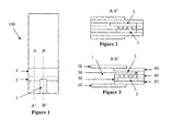
- Figure 1 shows an example of a first embodiment of the invention
- Figure 2 is a sectional view along section line A-A' of the embodiment shown in Figure 1 ;
- Figure 3 is a sectional view along section line B-B' of the embodiment shown in Figure 1 ;
- Figure 4 shows an example of a second embodiment of the invention
- Figure 5 is a sectional view along section line A-A' of the embodiment shown in Figure 4 ;
- Figure 6 is a sectional view along section line B-B' of the embodiment shown in Figure 4 ;
- FIG. 7 shows an alternate embodiment of the invention
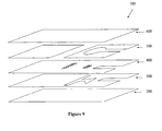
- Figure 8 shows an example of a third embodiment of the invention
- Figure 9 is an exploded view of the embodiment shown in Figure 8 ;
- Figure 10 is a graph showing current as a function of time of a first example of the invention.
- Figure 11 is a graph showing current as a function of time of a second example of the invention.
- This embodiment relates to a disposable immunoassay strip using electrochemical detection of the results of an immuno-binding reaction.
- the terms upper and lower are used for convenience only in the following description, they do not imply anything about the preferred orientation of the device during use, which can in fact be used in any orientation.
- the strip comprises three chambers, a filling chamber, a reaction chamber and a detection chamber.
- the filling chamber serves to receive the sample and act as a sample reservoir
- the reaction chamber contains reagents whereby a probe is selectively immobilized in the reaction chamber to differing extents dependent upon the presence or concentration of an analyte in the sample.
- the detection chamber contains electrodes and reagents so as to be able to detect the amount of probe transferred with liquid from the reaction chamber and thus detect or quantify the amount of analyte in the original sample.
- An example of such a strip is shown in Figures 1-3 .
- the strip 100 has a number of layers which are laminated together using adhesives.
- the strip has three chambers, a filling chamber 1, a reaction chamber 2, and a detection chamber 3.
- Layers 10 and 70 are sealing layers that serve to close the faces of chamber 1 to help to form a capillary space.
- Layer 20 is a layer carrying an electrically conductive upper surface which serves as an electrode in detection chamber 3.
- Layers 30 and 50 are spacer layers which have adhesive upper and lower faces. Layers 30 and 50 serve to hold the laminate together and to define the height of the detection and reaction chambers, respectively.
- a region cut-out of layer 30 shown in Figures 2 and 3 defines the area of detection chamber 3 and the area of the detection chamber electrodes.
- a region cut-out of layer 50 shown in Figures 2 and 3 defines the area of reaction chamber 2.
- Layer 40 is a layer containing pores which serve as pores that connect reaction chamber 2 to detection chamber 3.
- Layer 40 has an electrically conductive coating on its lower surface that serves as the second electrode in detection chamber 3.
- Layer 60 serves to close reaction chamber 2 and filling chamber 1.
- layer 60 can carry an electrically conductive coating on its lower surface to serve as an electrode to detect when liquid fills reaction chamber 2. With this option, liquid fills reaction chamber 2 and the pores in 40, thus bridging the electrode on the lower face of 40 and that on the lower face of 60. This bridging can be detected to tell the meter to initiate the test sequence.
- Layers 10 and 70 can be secured to layers 20 and 60, respectively, by any suitable method.
- a preferred method is to use adhesive.
- the adhesive can be applied to the lower surface of layer 20 and the upper surface of layer 60, layers 10 and 70 can then be laminated to these adhesive layers. Alternatively, adhesive can be coated on to layers 10 and 70 and then those layers laminated to 20 and 60.
- Figures 4-6 show an alternative embodiment where the cut-out in layer 50 to form reaction chamber 2 is such that the walls of the cut-out fully surround the cut-out to form an enclosed area.
- This embodiment has the advantage of preventing liquid from reaction chamber 2 wetting around the open edge of reaction chamber 2 to fill detection chamber 3 from its open edge, rather than through the porous wall connecting the two chambers.
- the air that is displaced as liquid fills reaction chamber 2 can vent through the holes in the porous wall, allowing the chamber to fill until all the pores in the wall are filled with liquid or reaction chamber 2 is fully filled. Note that it is not necessary for reaction chamber 2 to be completely filled for correct operation, just that there is a sufficient volume of liquid in contact with the reagents in reaction chamber 2 to fill detection chamber 3.
- FIG. 4-6 Also shown in Figures 4-6 is an embodiment where layers 10 and 70 are not required and instead layers 20 and 60 are extended to form the end walls of filling chamber 1.
- the conductive layer on the upper surface of 20 can be extended into filling chamber 1. If this is done, when liquid fills reaction chamber 2 and the pores of layer 40, electrical connection is made via the liquid between the conductive layer on 20 in filling chamber 1 and the conductive layer on the lower surface of layer 40. This can be detected electrically as a drop in the resistance or a change in the voltage, or current flowing or capacitance between the conductive layers on 20 and 40. This can serve as a signal to the meter that liquid has filled detection chamber 3 and thus automatically initiate a pre-determined test sequence.
- an advantage of this method is that the signal won't be detected until the liquid in filling chamber 1 is of sufficient volume to touch the opening of reaction chamber 2 and start to fill the pores of layer 40. Similar to the method disclosed in US 6,571,651 , the capillary dimension of filling chamber 1 is greater than that of reaction chamber 2, thus filling chamber 1 can empty to fill reaction chamber 2. So if filling chamber 1 is sized so as to have a volume at least equal to and preferably slightly greater than reaction chamber 2, then the signal indicating that liquid has been introduced into the device will not be detected until there is sufficient liquid introduced for the device to function as intended. An additional advantage of this is that if at first not enough liquid is introduced into filling chamber 1, more can be added until enough is present without affecting the intended operation of the device.
- An advantage of this embodiment is that only two electrical connections are required to detect all the electrical signals from the strip to complete the test, one connection to the conductive layer on 20 and the second to the conductive layer on 40. Suitable connectors for this are disclosed in US Patent Nos. 6,379,513 and 6,946,067 , and in US Patent Application No. 11/284,136 .
- connection device 200 is illustrated with reference to the present invention, however it is to be understood that this aspect of the invention is applicable to any device when it is desired that connection be made to surfaces that are in close proximity and face one another.
- the numbered elements in Figure 7 with numbers common to the other figures denote the same element in the present illustration.
- Figure 7 shows the end of the strip opposite to the end onto which filling chamber 1 opens.
- layer 20 is extended beyond spacer layer 30 and layer 40.
- Layer 20 carries an electrically conductive layer 70 on its upper surface and layer 40 carries an electrically conductive layer 90 on its lower surface. It is desired to make separate electrical connection to layers 70 and 90.
- Layer 40 is extended beyond spacer layer 30.
- An additional layer 110 is introduced into the space between layers 20 and 40 that extends beyond 30.
- the thickness of layer 110 plus a conductive layer 80 and any adhesive layers that may be present is to equal to or slightly greater than the thickness of layer 30.
- Layer 110 is electrically conductive at least on its upper surface 80 however is not electrically conductive through its full thickness, such that electrical connection can be made between 80 and 90 but not between 90 and 70 via 110.
- Layer 110 and conductive layer 80 carried thereupon extend beyond the edge of 40, thus by bringing 80 and 90 into electrical connection, electrical connection can be made to 90 via 80 in the area of 80 that extends beyond 40.
- an adhesive layer is present between the lower surface of 110 and 70 to fix layer 110 in position.
- a conductive adhesive can optionally be placed between layers 90 and 80, in at least a portion of where they overlap, to help ensure good electrical connection.
- the port containing the pins or similar devices to connect the strip to an external electrical circuit can be configured such that when the strip is inserted into the port, a face or faces of the port push against the upper surface of 40 to push 90 into connection with 80.
- FIG. 8 shows a top view of a device with three active chambers and a filling chamber.
- Figure 9 shows an exploded view of this embodiment showing the various layers.
- the strip 700 comprises a filling chamber 800, a first reaction chamber 510, a transfer and reaction chamber 310 and a second reaction chamber 520.
- Perforations 410 in layer 400 serve to connect first reaction chamber 510 with transfer and reaction chamber 310.
- Perforations 420 in layer 400 serve to connect transfer and reaction chamber 310 with second reaction chamber 520.
- sample is added to filling chamber 800 until it fills to the opening to 510 at the end of filling chamber 800, whereupon the sample fills first reaction chamber 510.
- first reaction chamber 510 The air that is necessarily displaced during this filling process will vent through the open ends of second reaction chamber 520, via perforations 410 and 420.
- One or more reagents and reagent layers can be dried into first reaction chamber 510 to do a sample pretreatment step, for example.
- the transfer of fluid to transfer and reaction chamber 310 can be initiated by the means disclosed, such as pushing on layer 200 from below until it contacts the lower surface of layer 400 at the perforated area 410.
- treated sample will flow from first reaction chamber 510 to fill transfer and reaction chamber 310 until perforations 420 are blocked with liquid sample such that air can no longer vent through perforations 420.
- first reaction chamber 510 could correspond to the reaction chamber of the embodiment shown in Figures 1-7 and second reaction chamber 520 could function as the detection chamber.
- transfer and reaction chamber 310 acts purely as a transfer chamber which separates first reaction chamber 510 and second reaction chamber 520 laterally as well as by perforated area 420. This can be advantageous in some applications in minimizing vapor from the fluid in first reaction chamber 510, when filled, from diffusing to second reaction chamber 520 and wetting the reagents prematurely.
- a further transfer of sample from transfer and reaction chamber 310 to second reaction chamber 520 can occur via perforations 420.
- This transfer can be initiated, for example, by pushing on the upper surface of layer 600 above perforations 420 such that the lower surface of layer 600 comes into contact with at least some of perforations 420.
- Further reagents can be dried into second reaction chamber 520 to further treat or react with components of the sample.
- the results of any reactions carried out in transfer and reaction chamber 310 and first reaction chamber 510 can be detected in second reaction chamber 520 and converted into a usable signal, either optical, electrochemical or for some other suitable method.
- Layers 200 and 600 are the lower and upper closing layers, respectively, whose functions are to close faces of the capillary spaces in the strip, provide layers to contact the perforated layer to initiate fluid transfer if initiation is performed in this manner, and to serve as supports on to which one or more other layers may be placed.
- Examples of other layers are layers of conductive material to form electrodes and electrical connection tracks and dried reagent layers that may be required to process the sample in the various chambers.
- Layer 500 is an upper spacer layer. Portions of layer 500 are either cut away or otherwise formed to define the area of first and second reaction chambers 510, 520.
- Layer 500 can be formed from a substrate with adhesive coated on both sides or may be just a layer of adhesive that has been formed or laid down with the areas that will correspond to first and second reaction chambers 510, 520 left free of adhesive. If an adhesive coated substrate is used, the areas corresponding to first and second reaction chambers 510, 520 could be formed by punching or otherwise removing those areas.
- Layer 400 is a layer that acts as a barrier between, and comprises the perforations necessary to complete the fluid transfers between, first reaction chamber 510 and transfer and reaction chamber 310 and transfer and reaction chamber 310 and second reaction chamber 520 when required.
- the perforations can be formed as described elsewhere in this disclosure.
- Layer 300 is a second spacer layer with an open area that serves to define transfer and reaction chamber 310. This can be constructed by the methods given above for layer 500.
- Filling chamber 800 can be formed by first laminating or otherwise joining layers 300, 400 and 500 with areas 310, 510 and 520 and perforations 410 and 420 pre-formed in the respective layers, and then punching through the tri-laminate to form the cut-out for filling chamber 800.
- the regions of 300, 400 and 500 that correspond to filling chamber 800 can be formed separately in the layers and then the layers laminated such that the cut-out regions align to form the side walls of filling chamber 800.
- the end faces of filling chamber 800 are closed when 200 and 600 are laminated to the upper and lower surfaces of the tri-laminate comprising 300,400 and 500.
- reagents can be dried into reaction chamber 2 and detection chamber 3 during fabrication.
- the reagents in reaction chamber 2 comprise a probe linked to a binding agent (hereafter termed the conjugate) and a binding target to which the binding agent can bind, where the species carrying the binding target, or the binding target itself, can be prevented from entering detection chamber 3.
- the conjugate can consist of an enzyme such as PQQ dependent glucose dehydrogenase (GDHpqq) linked to an antibody to an analyte of interest.
- GDHpqq PQQ dependent glucose dehydrogenase
- the target binding site can then be the analyte of interest tethered to magnetic beads.
- the magnetic beads can be prevented from entering the detection chamber by means of a magnet confining them to reaction chamber 3.
- the beads need not be magnetic but be large enough such that they cannot fit through the pores in layer 40, such that this prevents them from entering detection chamber 3.
- the free analyte can bind to the binding site on the conjugate and therefore block the conjugate from binding to the immobilized target sites.
- the conjugate therefore remains free in solution and so able to transfer to detection chamber 3.
- the conjugate and the target binding site are not mixed before the sample contacts the reagents.
- the conjugate can be dried onto the lower face of 60 and the species carrying the target binding sites onto the upper face of 40.
- a permanent or electromagnet placed next to the upper face of 60 can draw the beads up to mix with the conjugate after sample has filled reaction chamber 2 and freed the magnetic beads from the initially dry layer.
- the magnet serves to prevent the beads entering detection chamber 3.
- Detection chamber 3 also contains reagents dried down during strip fabrication. These reagents are those necessary to translate the presence of the probe into a current that can flow between the electrodes in detection chamber 3.
- a substrate and electrochemically active mediator for the enzyme can be incorporated.
- the substrate for the enzyme can be incorporated into reaction chamber 2. This has advantages where the substrate can take some time to become active.
- the probe is GDH
- glucose is a suitable substrate, however the GDHpqq is only active with ⁇ -D-glucose.
- D-glucose in the dried state is predominately in the form of ⁇ -D-glucose, which proceeds to mutarotate to ⁇ -D-glucose once it dissolves.
- any fluid containing a probe that enters the detection chamber will dissolve the dried chemicals and the chemicals and the probe begin to react.
- glucose is a suitable substrate and ferricyanide is a suitable mediator.
- ferricyanide is a suitable mediator.
- the GDHpqq will oxidize the glucose and be reduced in the process, the GDHpqq will then be reoxidised by ferricyanide, which forms ferrocyanide in the process.
- the ferrocyanide can then be oxidized at the anode in the detection chamber to produce a measurable current. This current can be related to the rate of production of ferrocyanide, which in turn can be related to the concentration of GDHpqq in the detection chamber, which in turn can be related to the concentration of analyte originally in the sample.
- the chemistry dried into the detection chamber should be dried onto the upper surface of 20. This prevents liquid filling the pores of 40 coming into contact with the dried reagents prematurely. Additionally, the dissolving of the chemistry on 20 in the reacted sample liquid when the chemistry contacts the liquid filled pores of 40 (as set out below) helps to encourage the transfer of liquid into the detection chamber.
- liquid from the reaction chamber In order for the GDHpqq to be detected in the detection chamber liquid from the reaction chamber must be transferred to the detection chamber after a pre-determined time when the binding reactions in the reaction chamber have proceeded to the desired point.
- the hydrophilicity of the pores in 40 are such that they also fill with liquid at this point.
- the liquid In this embodiment, in order to break the surface tension layer 20 is pushed from below in the region of the detection chamber. This distorts 20 such that its upper surface comes into contact with the lower surface of 40.
- the liquid can now exit the pores in 40 without increasing the air/liquid interface area by directly wetting the upper face of 20.
- the solution that wetted 20 moves away with it and draws more liquid through the pores of 40 in order to minimize the ratio of air/liquid interface to liquid volume as the surfaces move apart.
- This process draws liquid through the pores until eventually the detection chamber is completely filled.
- both the reaction chamber and the detection chamber should be open to the atmosphere when they are being filled for correct function, so that air can be displaced and vented during the filling processes.
- a venting function is provided by the reaction and detection chambers opening to the sides of the strip 100.
- the detection chamber is vented through its openings to the sides of the strip and the reaction chamber is vented through the open sides of the detection chamber via the pores in 40.
- the filling of the detection chamber does not result in the emptying of a chamber with similar capillary dimensions, as the two forces can oppose one another and create a slow or incomplete fill.
- the filling chamber has a larger capillary dimension than either the reaction or the detection chamber.
- the filling chamber will empty if there is no excess liquid attached to the filling chamber. Since the filling chamber has a larger capillary dimension than the detection chamber, the filling of the detection chamber will be less impeded.
- the detection chamber should be more hydrophilic than the filling chamber in order to affect the transfer of liquid.
- the invention has a number of advantages over the related art.
- a pusher mechanism rather than a piercing mechanism can be used to initiate fluid transfer, which should add robustness to the system.
- the chambers can be stacked one upon the other, leading to miniaturization and manufacturing advantages.
- multiple chambers can be stacked and offset, with multiple pusher mechanisms, as exemplified in Figures 8 and 9 , thus allowing multiple chambers in either parallel or series to be filled as desired times, increasing flexibility.
- electrode areas in the detection cell can be more conveniently defined since a cut-out region in 30 can entirely define the electrode areas.
- Melinex 329 was sputter coated with a thin layer of palladium to give an electrical resistance of 10 Ohms/sq to form layer 20.
- 0.002 inch thick Melinex 329 was coated with ca. 22 microns of heat activated adhesive ARCare-90503 (Adhesives Research Inc) on both sides to serve as layers 30 and 50.
- the adhesive tape was supplied with siliconised PET release liners on both faces.
- a 0.004 inch thick web of PET was perforated by laser cutting through holes in lines in the down-web direction.
- the holes were conical in shape with the larger end being 150 micron diameter and the smaller end being 45 microns in diameter.
- the average hole density was 8.2 holes/mm 2 .
- one side of the web was sputter coated with gold to give an electrical resistance of 10 Ohms/sq.
- the double sided adhesive tape was laminated to both sides of the perforated PET leaving the gaps as shown in Figure 1 which would form the reaction chamber 2 and the detection chamber 3.
- the palladium coated Melinex was then laminated to the lower face of layer 30 to form layer 20.
- Clear PET film was laminated to the upper face of layer 50 to form layer 60.
- Filling chamber 1 was then formed by punching through layers 20 to 60 and laminating adhesive coated PET film layers 10 and 70 to close the faces of filling chamber 1.
- Conjugate and derivatised magnetic beads were prepared as per US Patent Application Publication No. US-2006-0134713-A1 , herein incorporated by reference.
- the conjugate comprised an antibody to CRP (C-Reactive Protein) joined to at least one GDHpqq.
- CRP C-Reactive Protein
- the surface of the magnetic beads were modified to comprise CRP. This CRP served as the immobilized binding site for the conjugate.
- the magnetic beads were prevented from entering the detection chamber by a permanent magnet placed near the reaction chamber.
- the conjugate was dried onto the lower face of layer 60. In some strips beads were dried on the upper face of layer 40. A mixture of potassium ferricyanide, glucose and buffer was dried on the upper surface of layer 20. During testing a permanent magnet was placed adjacent to the upper face of layer 60. This served the dual purpose of preventing beads (if present) entering the detection chamber and attracting the beads towards the layer of conjugate to promote mixing of the two once the sample was introduced into the reaction chamber.
- sample was introduced into filling chamber 1 until it filled across to touch the entrance to reaction chamber 2, whereupon reaction chamber 2 also filled with sample. Sixty seconds was then allowed to elapse. After sixty seconds, a metal rod was pressed against the lower surface of 20 such that 20 was deflected up until the upper surface of 20 came into contact with liquid filling the holes in layer 40, whereupon liquid flowed through the holes in 40 to completely fill detection chamber 3.
- the meter initiated an electrochemical test sequence, where it made the lower electrode +300 mV relative to the upper electrode for 16 seconds.
- Figure 10 shows plots of the typical current response for strips filled with 0.1 M HEPES buffer in water with and without the presence of CRP labeled beads in the test solution.
- maximal conjugate should be transferred to detection chamber 3.
- the conjugate is substantially immobilised on the beads leading to a minimal transfer of conjugate to detection chamber 3.
- the lower electrode was at +300 mV with respect to the upper electrode during the sixteen seconds the potential was applied.
- Figure 11 shows typical current responses for strips with conjugate and beads dried into them when tested blood serum containing either zero or 250 micrograms/milliliter of CRP.
- the upper electrode was at +300 mV with respect to the lower electrode.
- the invention is also pertinent to a sensor with a single, larger punched hole in layer 40 rather than a series of small, laser formed holes.
- a 1.5 mm diameter male/female punch was used to create a hole in layer 40.
- liquid filled chamber 2 it stopped just past the edge of the hole.
- layer 20 was pushed against the hole, the liquid entered chamber 3.
- the invention is not restricted to the number of holes per sensor or the range of hole diameters described in Examples 1 and 2.
Landscapes
- Chemical & Material Sciences (AREA)
- Engineering & Computer Science (AREA)
- General Engineering & Computer Science (AREA)
- Dispersion Chemistry (AREA)
- Mechanical Engineering (AREA)
- Health & Medical Sciences (AREA)
- Chemical Kinetics & Catalysis (AREA)
- Analytical Chemistry (AREA)
- General Health & Medical Sciences (AREA)
- Hematology (AREA)
- Clinical Laboratory Science (AREA)
- Investigating Or Analysing Biological Materials (AREA)
- Automatic Analysis And Handling Materials Therefor (AREA)
- Apparatus Associated With Microorganisms And Enzymes (AREA)
- Reciprocating Pumps (AREA)
Priority Applications (2)
| Application Number | Priority Date | Filing Date | Title |
|---|---|---|---|
| PL07705600T PL1987353T3 (pl) | 2006-02-21 | 2007-02-15 | Mechanizm przenoszenia płynu |
| SI200731013T SI1987353T1 (sl) | 2006-02-21 | 2007-02-15 | Mehanizem za prenos fluida |
Applications Claiming Priority (2)
| Application Number | Priority Date | Filing Date | Title |
|---|---|---|---|
| US77467806P | 2006-02-21 | 2006-02-21 | |
| PCT/IB2007/000370 WO2007096730A1 (en) | 2006-02-21 | 2007-02-15 | Fluid transfer mechanism |
Publications (3)
| Publication Number | Publication Date |
|---|---|
| EP1987353A1 EP1987353A1 (en) | 2008-11-05 |
| EP1987353A4 EP1987353A4 (en) | 2010-11-17 |
| EP1987353B1 true EP1987353B1 (en) | 2012-06-13 |
Family
ID=38436990
Family Applications (1)
| Application Number | Title | Priority Date | Filing Date |
|---|---|---|---|
| EP07705600A Not-in-force EP1987353B1 (en) | 2006-02-21 | 2007-02-15 | Fluid transfer mechanism |
Country Status (18)
| Country | Link |
|---|---|
| US (1) | US8182765B2 (enExample) |
| EP (1) | EP1987353B1 (enExample) |
| JP (1) | JP5154452B2 (enExample) |
| KR (1) | KR101345428B1 (enExample) |
| CN (1) | CN101384900B (enExample) |
| AU (1) | AU2007219203B2 (enExample) |
| BR (1) | BRPI0708131A2 (enExample) |
| CA (1) | CA2643370C (enExample) |
| DK (1) | DK1987353T3 (enExample) |
| ES (1) | ES2389382T3 (enExample) |
| IL (1) | IL193352A (enExample) |
| MX (1) | MX2008010719A (enExample) |
| NZ (1) | NZ571322A (enExample) |
| PL (1) | PL1987353T3 (enExample) |
| PT (1) | PT1987353E (enExample) |
| TW (1) | TWI402341B (enExample) |
| WO (1) | WO2007096730A1 (enExample) |
| ZA (1) | ZA200807527B (enExample) |
Families Citing this family (21)
| Publication number | Priority date | Publication date | Assignee | Title |
|---|---|---|---|---|
| US8137626B2 (en) | 2006-05-19 | 2012-03-20 | California Institute Of Technology | Fluorescence detector, filter device and related methods |
| US8187541B2 (en) * | 2006-09-18 | 2012-05-29 | California Institute Of Technology | Apparatus for detecting target molecules and related methods |
| EP2072133A1 (en) | 2007-12-20 | 2009-06-24 | Koninklijke Philips Electronics N.V. | Multi-compartment device with magnetic particles |
| WO2010016916A2 (en) * | 2008-08-07 | 2010-02-11 | The University Of North Carolina At Chapel Hill | Method of creating removable barriers in microfabricated fluidic devices |
| JP5847074B2 (ja) | 2009-04-17 | 2016-01-20 | ユニバーサル バイオセンサーズ ピーティーワイ リミテッドUniversal Biosensors Pty Limited | 基板上対照検出 |
| EP2451576B1 (en) * | 2009-07-09 | 2019-06-12 | Alere Switzerland GmbH | Device and method for analyzing analyte in liquid sample |
| WO2012092394A1 (en) | 2010-12-29 | 2012-07-05 | Cardinal Health 414, Llc | Closed vial fill system for aseptic dispensing |
| US8956518B2 (en) | 2011-04-20 | 2015-02-17 | Lifescan, Inc. | Electrochemical sensors with carrier field |
| US20130020727A1 (en) | 2011-07-15 | 2013-01-24 | Cardinal Health 414, Llc. | Modular cassette synthesis unit |
| US20130102772A1 (en) | 2011-07-15 | 2013-04-25 | Cardinal Health 414, Llc | Systems, methods and devices for producing, manufacturing and control of radiopharmaceuticals-full |
| US9417332B2 (en) | 2011-07-15 | 2016-08-16 | Cardinal Health 414, Llc | Radiopharmaceutical CZT sensor and apparatus |
| WO2013036617A1 (en) | 2011-09-06 | 2013-03-14 | President And Fellows Of Harvard College | Microfluidic devices for multiplexed electrochemical detection |
| US9623407B2 (en) * | 2015-03-27 | 2017-04-18 | International Business Machines Corporation | Microfluidic device with longitudinal and transverse liquid barriers for transverse flow mixing |
| WO2017040946A1 (en) * | 2015-09-03 | 2017-03-09 | The Charles Stark Draper Laboratory, Inc. | Modular chemical sensor platform |
| US11499962B2 (en) | 2017-11-17 | 2022-11-15 | Ultima Genomics, Inc. | Methods and systems for analyte detection and analysis |
| US10273528B1 (en) | 2017-11-17 | 2019-04-30 | Ultima Genomics, Inc. | Methods and systems for analyte detection and analysis |
| US10512911B1 (en) | 2018-12-07 | 2019-12-24 | Ultima Genomics, Inc. | Implementing barriers for controlled environments during sample processing and detection |
| US12239980B2 (en) | 2018-12-07 | 2025-03-04 | Ultima Genomics, Inc. | Implementing barriers for controlled environments during sample processing and detection |
| CN209829010U (zh) * | 2019-03-01 | 2019-12-24 | 南京岚煜生物科技有限公司 | 一种多通道微流体凝血检测芯片 |
| US11118223B2 (en) | 2019-03-14 | 2021-09-14 | Ultima Genomics, Inc. | Methods, devices, and systems for analyte detection and analysis |
| WO2020194179A1 (en) * | 2019-03-24 | 2020-10-01 | Baldwa Mehul | Biosensor for detection of analytes in a fluid |
Family Cites Families (23)
| Publication number | Priority date | Publication date | Assignee | Title |
|---|---|---|---|---|
| US4426451A (en) | 1981-01-28 | 1984-01-17 | Eastman Kodak Company | Multi-zoned reaction vessel having pressure-actuatable control means between zones |
| JP3717983B2 (ja) * | 1995-11-07 | 2005-11-16 | シチズン時計株式会社 | 液体吐出方法及びその装置 |
| AUPO581397A0 (en) | 1997-03-21 | 1997-04-17 | Memtec America Corporation | Sensor connection means |
| US6565813B1 (en) * | 1998-02-04 | 2003-05-20 | Merck & Co., Inc. | Virtual wells for use in high throughput screening assays |
| GB9809943D0 (en) | 1998-05-08 | 1998-07-08 | Amersham Pharm Biotech Ab | Microfluidic device |
| US6485690B1 (en) * | 1999-05-27 | 2002-11-26 | Orchid Biosciences, Inc. | Multiple fluid sample processor and system |
| US6878255B1 (en) * | 1999-11-05 | 2005-04-12 | Arrowhead Center, Inc. | Microfluidic devices with thick-film electrochemical detection |
| US6571651B1 (en) | 2000-03-27 | 2003-06-03 | Lifescan, Inc. | Method of preventing short sampling of a capillary or wicking fill device |
| US6561208B1 (en) | 2000-04-14 | 2003-05-13 | Nanostream, Inc. | Fluidic impedances in microfluidic system |
| RU2278612C2 (ru) | 2000-07-14 | 2006-06-27 | Лайфскен, Инк. | Иммуносенсор |
| US6536477B1 (en) * | 2000-10-12 | 2003-03-25 | Nanostream, Inc. | Fluidic couplers and modular microfluidic systems |
| DE10101326A1 (de) * | 2001-01-13 | 2002-07-25 | Fraunhofer Ges Forschung | Verfahren zur Herstellung von emulgierfähigen Proteinprodukten aus einer Ölsaat |
| US6946067B2 (en) | 2002-01-04 | 2005-09-20 | Lifescan, Inc. | Method of forming an electrical connection between an electrochemical cell and a meter |
| AU2003215340A1 (en) * | 2002-02-22 | 2003-09-09 | Nanostream, Inc. | Ratiometric dilution devices and methods |
| US20060134713A1 (en) | 2002-03-21 | 2006-06-22 | Lifescan, Inc. | Biosensor apparatus and methods of use |
| KR100444751B1 (ko) * | 2002-11-11 | 2004-08-16 | 한국전자통신연구원 | 표면장력에 의한 유체제어 소자 |
| US7125711B2 (en) * | 2002-12-19 | 2006-10-24 | Bayer Healthcare Llc | Method and apparatus for splitting of specimens into multiple channels of a microfluidic device |
| US20040265172A1 (en) * | 2003-06-27 | 2004-12-30 | Pugia Michael J. | Method and apparatus for entry and storage of specimens into a microfluidic device |
| US7722817B2 (en) | 2003-08-28 | 2010-05-25 | Epocal Inc. | Lateral flow diagnostic devices with instrument controlled fluidics |
| EP1728062A4 (en) * | 2004-03-26 | 2012-12-26 | Univ Laval | REMOVABLE MICROFLUID FLOW CELL |
| US20060002817A1 (en) * | 2004-06-30 | 2006-01-05 | Sebastian Bohm | Flow modulation devices |
| JP4617743B2 (ja) * | 2004-07-06 | 2011-01-26 | ソニー株式会社 | 機能素子およびその製造方法、ならびに流体吐出ヘッド |
| US8192599B2 (en) | 2005-05-25 | 2012-06-05 | Universal Biosensors Pty Ltd | Method and apparatus for electrochemical analysis |
-
2007
- 2007-02-15 MX MX2008010719A patent/MX2008010719A/es active IP Right Grant
- 2007-02-15 EP EP07705600A patent/EP1987353B1/en not_active Not-in-force
- 2007-02-15 PT PT07705600T patent/PT1987353E/pt unknown
- 2007-02-15 CN CN2007800059677A patent/CN101384900B/zh not_active Expired - Fee Related
- 2007-02-15 AU AU2007219203A patent/AU2007219203B2/en not_active Ceased
- 2007-02-15 JP JP2008554877A patent/JP5154452B2/ja not_active Expired - Fee Related
- 2007-02-15 ES ES07705600T patent/ES2389382T3/es active Active
- 2007-02-15 NZ NZ571322A patent/NZ571322A/en not_active IP Right Cessation
- 2007-02-15 US US12/280,317 patent/US8182765B2/en not_active Expired - Fee Related
- 2007-02-15 DK DK07705600.0T patent/DK1987353T3/da active
- 2007-02-15 TW TW096105823A patent/TWI402341B/zh not_active IP Right Cessation
- 2007-02-15 BR BRPI0708131-6A patent/BRPI0708131A2/pt not_active IP Right Cessation
- 2007-02-15 CA CA2643370A patent/CA2643370C/en not_active Expired - Fee Related
- 2007-02-15 WO PCT/IB2007/000370 patent/WO2007096730A1/en not_active Ceased
- 2007-02-15 PL PL07705600T patent/PL1987353T3/pl unknown
-
2008
- 2008-08-10 IL IL193352A patent/IL193352A/en not_active IP Right Cessation
- 2008-09-02 ZA ZA200807527A patent/ZA200807527B/xx unknown
- 2008-09-19 KR KR1020087022938A patent/KR101345428B1/ko not_active Expired - Fee Related
Also Published As
| Publication number | Publication date |
|---|---|
| PT1987353E (pt) | 2012-09-06 |
| JP2009527676A (ja) | 2009-07-30 |
| CN101384900B (zh) | 2013-06-05 |
| IL193352A0 (en) | 2009-05-04 |
| NZ571322A (en) | 2011-08-26 |
| CA2643370A1 (en) | 2007-08-30 |
| BRPI0708131A2 (pt) | 2011-05-17 |
| HK1124665A1 (en) | 2009-07-17 |
| ES2389382T3 (es) | 2012-10-25 |
| TW200813215A (en) | 2008-03-16 |
| EP1987353A1 (en) | 2008-11-05 |
| US8182765B2 (en) | 2012-05-22 |
| AU2007219203B2 (en) | 2012-12-20 |
| JP5154452B2 (ja) | 2013-02-27 |
| ZA200807527B (en) | 2009-07-29 |
| KR20090034298A (ko) | 2009-04-07 |
| US20090305431A1 (en) | 2009-12-10 |
| DK1987353T3 (da) | 2012-09-10 |
| CA2643370C (en) | 2014-06-03 |
| CN101384900A (zh) | 2009-03-11 |
| EP1987353A4 (en) | 2010-11-17 |
| WO2007096730A1 (en) | 2007-08-30 |
| KR101345428B1 (ko) | 2013-12-27 |
| PL1987353T3 (pl) | 2012-11-30 |
| AU2007219203A1 (en) | 2007-08-30 |
| TWI402341B (zh) | 2013-07-21 |
| MX2008010719A (es) | 2008-09-01 |
| IL193352A (en) | 2014-01-30 |
Similar Documents
| Publication | Publication Date | Title |
|---|---|---|
| EP1987353B1 (en) | Fluid transfer mechanism | |
| JP5288700B2 (ja) | バイオセンサー装置及びその使用方法 | |
| KR100884501B1 (ko) | 면역센서 | |
| EP2646152B1 (en) | Sample metering device and assay device with integrated sample dilution | |
| EP1481246B1 (en) | Apparatus and methods for analyte measurement and immunoassay | |
| US20060141469A1 (en) | Multi-layered electrochemical microfluidic sensor comprising reagent on porous layer | |
| US9846152B2 (en) | Assay devices with integrated sample dilution and dilution verification and methods of using same | |
| EP2646153B1 (en) | Sample metering device and assay device with integrated sample dilution | |
| EP2205357B1 (en) | Assay device and method | |
| WO2012075258A2 (en) | Ratiometric immunoassay method and blood testing device | |
| HK1124665B (en) | Fluid transfer mechanism | |
| JP4929427B2 (ja) | 免疫学的センサ | |
| JP2009092514A (ja) | 試料液分析チップ、および試料液の移送制御方法 | |
| HK1151589A (en) | Biosensor apparatus and methods of use | |
| HK1141753A (en) | Assay device and method | |
| HK1141753B (en) | Assay device and method |
Legal Events
| Date | Code | Title | Description |
|---|---|---|---|
| PUAI | Public reference made under article 153(3) epc to a published international application that has entered the european phase |
Free format text: ORIGINAL CODE: 0009012 |
|
| 17P | Request for examination filed |
Effective date: 20080902 |
|
| AK | Designated contracting states |
Kind code of ref document: A1 Designated state(s): AT BE BG CH CY CZ DE DK EE ES FI FR GB GR HU IE IS IT LI LT LU LV MC NL PL PT RO SE SI SK TR |
|
| REG | Reference to a national code |
Ref country code: HK Ref legal event code: DE Ref document number: 1124665 Country of ref document: HK |
|
| A4 | Supplementary search report drawn up and despatched |
Effective date: 20101014 |
|
| 17Q | First examination report despatched |
Effective date: 20110614 |
|
| GRAP | Despatch of communication of intention to grant a patent |
Free format text: ORIGINAL CODE: EPIDOSNIGR1 |
|
| RIC1 | Information provided on ipc code assigned before grant |
Ipc: B01L 3/00 20060101ALI20111212BHEP Ipc: G01N 33/53 20060101ALI20111212BHEP Ipc: B81B 1/00 20060101ALI20111212BHEP Ipc: G01N 33/49 20060101AFI20111212BHEP |
|
| GRAS | Grant fee paid |
Free format text: ORIGINAL CODE: EPIDOSNIGR3 |
|
| GRAA | (expected) grant |
Free format text: ORIGINAL CODE: 0009210 |
|
| AK | Designated contracting states |
Kind code of ref document: B1 Designated state(s): AT BE BG CH CY CZ DE DK EE ES FI FR GB GR HU IE IS IT LI LT LU LV MC NL PL PT RO SE SI SK TR |
|
| DAX | Request for extension of the european patent (deleted) | ||
| REG | Reference to a national code |
Ref country code: GB Ref legal event code: FG4D |
|
| REG | Reference to a national code |
Ref country code: AT Ref legal event code: REF Ref document number: 562208 Country of ref document: AT Kind code of ref document: T Effective date: 20120615 Ref country code: CH Ref legal event code: EP |
|
| BECA | Be: change of holder's address |
Owner name: UNIVERSAL BIOSENSORS PTY LTD Effective date: 20120613 Owner name: 1 CORPORATION AVENUE, ROWVILLE VIC 3178 Effective date: 20120613 |
|
| REG | Reference to a national code |
Ref country code: IE Ref legal event code: FG4D |
|
| REG | Reference to a national code |
Ref country code: CH Ref legal event code: NV Representative=s name: E. BLUM & CO. AG PATENT- UND MARKENANWAELTE VSP |
|
| REG | Reference to a national code |
Ref country code: DE Ref legal event code: R096 Ref document number: 602007023320 Country of ref document: DE Effective date: 20120816 |
|
| REG | Reference to a national code |
Ref country code: PT Ref legal event code: SC4A Free format text: AVAILABILITY OF NATIONAL TRANSLATION Effective date: 20120830 |
|
| REG | Reference to a national code |
Ref country code: DK Ref legal event code: T3 |
|
| REG | Reference to a national code |
Ref country code: NL Ref legal event code: T3 |
|
| REG | Reference to a national code |
Ref country code: SE Ref legal event code: TRGR |
|
| REG | Reference to a national code |
Ref country code: CH Ref legal event code: PFA Owner name: UNIVERSAL BIOSENSORS PTY LIMITED Free format text: UNIVERSAL BIOSENSORS PTY LIMITED#103 RICKETTS ROAD#MOUNT WAVERLEY, VIC 3149 (AU) -TRANSFER TO- UNIVERSAL BIOSENSORS PTY LIMITED#1 CORPORATE AVENUE#ROWVILLE, VIC 3178 (AU) |
|
| RAP2 | Party data changed (patent owner data changed or rights of a patent transferred) |
Owner name: UNIVERSAL BIOSENSORS PTY LIMITED |
|
| RAP2 | Party data changed (patent owner data changed or rights of a patent transferred) |
Owner name: UNIVERSAL BIOSENSORS PTY LIMITED |
|
| REG | Reference to a national code |
Ref country code: ES Ref legal event code: FG2A Ref document number: 2389382 Country of ref document: ES Kind code of ref document: T3 Effective date: 20121025 |
|
| REG | Reference to a national code |
Ref country code: FR Ref legal event code: CA Effective date: 20120926 |
|
| REG | Reference to a national code |
Ref country code: GR Ref legal event code: EP Ref document number: 20120402045 Country of ref document: GR Effective date: 20120915 |
|
| PG25 | Lapsed in a contracting state [announced via postgrant information from national office to epo] |
Ref country code: CY Free format text: LAPSE BECAUSE OF FAILURE TO SUBMIT A TRANSLATION OF THE DESCRIPTION OR TO PAY THE FEE WITHIN THE PRESCRIBED TIME-LIMIT Effective date: 20120613 Ref country code: LT Free format text: LAPSE BECAUSE OF FAILURE TO SUBMIT A TRANSLATION OF THE DESCRIPTION OR TO PAY THE FEE WITHIN THE PRESCRIBED TIME-LIMIT Effective date: 20120613 |
|
| REG | Reference to a national code |
Ref country code: LT Ref legal event code: MG4D Effective date: 20120613 |
|
| PG25 | Lapsed in a contracting state [announced via postgrant information from national office to epo] |
Ref country code: LV Free format text: LAPSE BECAUSE OF FAILURE TO SUBMIT A TRANSLATION OF THE DESCRIPTION OR TO PAY THE FEE WITHIN THE PRESCRIBED TIME-LIMIT Effective date: 20120613 |
|
| REG | Reference to a national code |
Ref country code: PL Ref legal event code: T3 |
|
| REG | Reference to a national code |
Ref country code: HU Ref legal event code: AG4A Ref document number: E014990 Country of ref document: HU |
|
| PG25 | Lapsed in a contracting state [announced via postgrant information from national office to epo] |
Ref country code: EE Free format text: LAPSE BECAUSE OF FAILURE TO SUBMIT A TRANSLATION OF THE DESCRIPTION OR TO PAY THE FEE WITHIN THE PRESCRIBED TIME-LIMIT Effective date: 20120613 Ref country code: SK Free format text: LAPSE BECAUSE OF FAILURE TO SUBMIT A TRANSLATION OF THE DESCRIPTION OR TO PAY THE FEE WITHIN THE PRESCRIBED TIME-LIMIT Effective date: 20120613 Ref country code: RO Free format text: LAPSE BECAUSE OF FAILURE TO SUBMIT A TRANSLATION OF THE DESCRIPTION OR TO PAY THE FEE WITHIN THE PRESCRIBED TIME-LIMIT Effective date: 20120613 Ref country code: IS Free format text: LAPSE BECAUSE OF FAILURE TO SUBMIT A TRANSLATION OF THE DESCRIPTION OR TO PAY THE FEE WITHIN THE PRESCRIBED TIME-LIMIT Effective date: 20121013 |
|
| REG | Reference to a national code |
Ref country code: HK Ref legal event code: GR Ref document number: 1124665 Country of ref document: HK |
|
| PLBE | No opposition filed within time limit |
Free format text: ORIGINAL CODE: 0009261 |
|
| STAA | Information on the status of an ep patent application or granted ep patent |
Free format text: STATUS: NO OPPOSITION FILED WITHIN TIME LIMIT |
|
| 26N | No opposition filed |
Effective date: 20130314 |
|
| REG | Reference to a national code |
Ref country code: DE Ref legal event code: R097 Ref document number: 602007023320 Country of ref document: DE Effective date: 20130314 |
|
| PG25 | Lapsed in a contracting state [announced via postgrant information from national office to epo] |
Ref country code: BG Free format text: LAPSE BECAUSE OF FAILURE TO SUBMIT A TRANSLATION OF THE DESCRIPTION OR TO PAY THE FEE WITHIN THE PRESCRIBED TIME-LIMIT Effective date: 20120913 |
|
| PG25 | Lapsed in a contracting state [announced via postgrant information from national office to epo] |
Ref country code: MC Free format text: LAPSE BECAUSE OF NON-PAYMENT OF DUE FEES Effective date: 20130228 |
|
| PGFP | Annual fee paid to national office [announced via postgrant information from national office to epo] |
Ref country code: TR Payment date: 20150127 Year of fee payment: 9 |
|
| PG25 | Lapsed in a contracting state [announced via postgrant information from national office to epo] |
Ref country code: LU Free format text: LAPSE BECAUSE OF NON-PAYMENT OF DUE FEES Effective date: 20130215 |
|
| REG | Reference to a national code |
Ref country code: FR Ref legal event code: PLFP Year of fee payment: 10 |
|
| REG | Reference to a national code |
Ref country code: FR Ref legal event code: PLFP Year of fee payment: 11 |
|
| REG | Reference to a national code |
Ref country code: FR Ref legal event code: PLFP Year of fee payment: 12 |
|
| PGFP | Annual fee paid to national office [announced via postgrant information from national office to epo] |
Ref country code: AT Payment date: 20200107 Year of fee payment: 14 Ref country code: FI Payment date: 20200107 Year of fee payment: 14 Ref country code: PT Payment date: 20200108 Year of fee payment: 14 Ref country code: ES Payment date: 20200303 Year of fee payment: 14 Ref country code: IT Payment date: 20200124 Year of fee payment: 14 Ref country code: DE Payment date: 20200107 Year of fee payment: 14 Ref country code: DK Payment date: 20200107 Year of fee payment: 14 Ref country code: GR Payment date: 20200107 Year of fee payment: 14 Ref country code: NL Payment date: 20200107 Year of fee payment: 14 Ref country code: SE Payment date: 20200107 Year of fee payment: 14 Ref country code: IE Payment date: 20200107 Year of fee payment: 14 Ref country code: GB Payment date: 20200107 Year of fee payment: 14 Ref country code: HU Payment date: 20200114 Year of fee payment: 14 |
|
| PGFP | Annual fee paid to national office [announced via postgrant information from national office to epo] |
Ref country code: SI Payment date: 20200114 Year of fee payment: 14 Ref country code: CZ Payment date: 20200212 Year of fee payment: 14 Ref country code: CH Payment date: 20200107 Year of fee payment: 14 Ref country code: BE Payment date: 20200107 Year of fee payment: 14 |
|
| PGFP | Annual fee paid to national office [announced via postgrant information from national office to epo] |
Ref country code: FR Payment date: 20200107 Year of fee payment: 14 |
|
| PGFP | Annual fee paid to national office [announced via postgrant information from national office to epo] |
Ref country code: PL Payment date: 20200113 Year of fee payment: 14 |
|
| REG | Reference to a national code |
Ref country code: DE Ref legal event code: R119 Ref document number: 602007023320 Country of ref document: DE |
|
| REG | Reference to a national code |
Ref country code: DK Ref legal event code: EBP Effective date: 20210228 |
|
| REG | Reference to a national code |
Ref country code: SE Ref legal event code: EUG |
|
| REG | Reference to a national code |
Ref country code: FI Ref legal event code: MAE |
|
| REG | Reference to a national code |
Ref country code: AT Ref legal event code: MM01 Ref document number: 562208 Country of ref document: AT Kind code of ref document: T Effective date: 20210215 |
|
| GBPC | Gb: european patent ceased through non-payment of renewal fee |
Effective date: 20210215 |
|
| REG | Reference to a national code |
Ref country code: BE Ref legal event code: MM Effective date: 20210228 |
|
| PG25 | Lapsed in a contracting state [announced via postgrant information from national office to epo] |
Ref country code: FI Free format text: LAPSE BECAUSE OF NON-PAYMENT OF DUE FEES Effective date: 20210215 Ref country code: CZ Free format text: LAPSE BECAUSE OF NON-PAYMENT OF DUE FEES Effective date: 20210215 Ref country code: LI Free format text: LAPSE BECAUSE OF NON-PAYMENT OF DUE FEES Effective date: 20210228 Ref country code: HU Free format text: LAPSE BECAUSE OF NON-PAYMENT OF DUE FEES Effective date: 20210216 Ref country code: CH Free format text: LAPSE BECAUSE OF NON-PAYMENT OF DUE FEES Effective date: 20210228 Ref country code: AT Free format text: LAPSE BECAUSE OF NON-PAYMENT OF DUE FEES Effective date: 20210215 |
|
| PG25 | Lapsed in a contracting state [announced via postgrant information from national office to epo] |
Ref country code: SE Free format text: LAPSE BECAUSE OF NON-PAYMENT OF DUE FEES Effective date: 20210216 Ref country code: GR Free format text: LAPSE BECAUSE OF NON-PAYMENT OF DUE FEES Effective date: 20210906 Ref country code: PT Free format text: LAPSE BECAUSE OF NON-PAYMENT OF DUE FEES Effective date: 20210816 |
|
| REG | Reference to a national code |
Ref country code: NL Ref legal event code: MM Effective date: 20210301 |
|
| PG25 | Lapsed in a contracting state [announced via postgrant information from national office to epo] |
Ref country code: NL Free format text: LAPSE BECAUSE OF NON-PAYMENT OF DUE FEES Effective date: 20210301 |
|
| PG25 | Lapsed in a contracting state [announced via postgrant information from national office to epo] |
Ref country code: DE Free format text: LAPSE BECAUSE OF NON-PAYMENT OF DUE FEES Effective date: 20210901 Ref country code: DK Free format text: LAPSE BECAUSE OF NON-PAYMENT OF DUE FEES Effective date: 20210228 Ref country code: GB Free format text: LAPSE BECAUSE OF NON-PAYMENT OF DUE FEES Effective date: 20210215 Ref country code: IE Free format text: LAPSE BECAUSE OF NON-PAYMENT OF DUE FEES Effective date: 20210215 Ref country code: FR Free format text: LAPSE BECAUSE OF NON-PAYMENT OF DUE FEES Effective date: 20210228 |
|
| REG | Reference to a national code |
Ref country code: SI Ref legal event code: KO00 Effective date: 20211129 |
|
| PG25 | Lapsed in a contracting state [announced via postgrant information from national office to epo] |
Ref country code: SI Free format text: LAPSE BECAUSE OF NON-PAYMENT OF DUE FEES Effective date: 20210216 |
|
| PG25 | Lapsed in a contracting state [announced via postgrant information from national office to epo] |
Ref country code: IT Free format text: LAPSE BECAUSE OF NON-PAYMENT OF DUE FEES Effective date: 20210215 |
|
| REG | Reference to a national code |
Ref country code: ES Ref legal event code: FD2A Effective date: 20220511 |
|
| PG25 | Lapsed in a contracting state [announced via postgrant information from national office to epo] |
Ref country code: TR Free format text: LAPSE BECAUSE OF NON-PAYMENT OF DUE FEES Effective date: 20160215 |
|
| PG25 | Lapsed in a contracting state [announced via postgrant information from national office to epo] |
Ref country code: ES Free format text: LAPSE BECAUSE OF NON-PAYMENT OF DUE FEES Effective date: 20210216 Ref country code: BE Free format text: LAPSE BECAUSE OF NON-PAYMENT OF DUE FEES Effective date: 20210228 |
|
| PG25 | Lapsed in a contracting state [announced via postgrant information from national office to epo] |
Ref country code: PL Free format text: LAPSE BECAUSE OF NON-PAYMENT OF DUE FEES Effective date: 20210215 |
|
| P01 | Opt-out of the competence of the unified patent court (upc) registered |
Effective date: 20230512 |