EP1985397A2 - Appareil à fileter sur une tour contrôlée numériquement - Google Patents
Appareil à fileter sur une tour contrôlée numériquement Download PDFInfo
- Publication number
- EP1985397A2 EP1985397A2 EP08007185A EP08007185A EP1985397A2 EP 1985397 A2 EP1985397 A2 EP 1985397A2 EP 08007185 A EP08007185 A EP 08007185A EP 08007185 A EP08007185 A EP 08007185A EP 1985397 A2 EP1985397 A2 EP 1985397A2
- Authority
- EP
- European Patent Office
- Prior art keywords
- threading
- threading device
- supporting assembly
- refrigerating
- electric
- Prior art date
- Legal status (The legal status is an assumption and is not a legal conclusion. Google has not performed a legal analysis and makes no representation as to the accuracy of the status listed.)
- Granted
Links
Images

Classifications
-
- B—PERFORMING OPERATIONS; TRANSPORTING
- B23—MACHINE TOOLS; METAL-WORKING NOT OTHERWISE PROVIDED FOR
- B23G—THREAD CUTTING; WORKING OF SCREWS, BOLT HEADS, OR NUTS, IN CONJUNCTION THEREWITH
- B23G1/00—Thread cutting; Automatic machines specially designed therefor
- B23G1/32—Thread cutting; Automatic machines specially designed therefor by milling
- B23G1/34—Thread cutting; Automatic machines specially designed therefor by milling with a cutting bit moving in a closed path arranged eccentrically with respect to the axis of the rotating workpieces
-
- A—HUMAN NECESSITIES
- A61—MEDICAL OR VETERINARY SCIENCE; HYGIENE
- A61B—DIAGNOSIS; SURGERY; IDENTIFICATION
- A61B17/00—Surgical instruments, devices or methods
- A61B17/56—Surgical instruments or methods for treatment of bones or joints; Devices specially adapted therefor
- A61B17/58—Surgical instruments or methods for treatment of bones or joints; Devices specially adapted therefor for osteosynthesis, e.g. bone plates, screws or setting implements
- A61B17/68—Internal fixation devices, including fasteners and spinal fixators, even if a part thereof projects from the skin
- A61B17/84—Fasteners therefor or fasteners being internal fixation devices
- A61B17/86—Pins or screws or threaded wires; nuts therefor
- A61B17/866—Material or manufacture
-
- B—PERFORMING OPERATIONS; TRANSPORTING
- B23—MACHINE TOOLS; METAL-WORKING NOT OTHERWISE PROVIDED FOR
- B23G—THREAD CUTTING; WORKING OF SCREWS, BOLT HEADS, OR NUTS, IN CONJUNCTION THEREWITH
- B23G2240/00—Details of equipment for threading other than threading tools, details of the threading process
- B23G2240/12—Means for cooling or lubrication
-
- B—PERFORMING OPERATIONS; TRANSPORTING
- B23—MACHINE TOOLS; METAL-WORKING NOT OTHERWISE PROVIDED FOR
- B23G—THREAD CUTTING; WORKING OF SCREWS, BOLT HEADS, OR NUTS, IN CONJUNCTION THEREWITH
- B23G2240/00—Details of equipment for threading other than threading tools, details of the threading process
- B23G2240/40—Threading equipment having an integrally incorporated driving motor
-
- B—PERFORMING OPERATIONS; TRANSPORTING
- B23—MACHINE TOOLS; METAL-WORKING NOT OTHERWISE PROVIDED FOR
- B23G—THREAD CUTTING; WORKING OF SCREWS, BOLT HEADS, OR NUTS, IN CONJUNCTION THEREWITH
- B23G2240/00—Details of equipment for threading other than threading tools, details of the threading process
- B23G2240/60—Thread whirling, i.e. production of a thread by means of an annular tool rotating about an axis not coincident with the axis of the thread being produced
-
- Y—GENERAL TAGGING OF NEW TECHNOLOGICAL DEVELOPMENTS; GENERAL TAGGING OF CROSS-SECTIONAL TECHNOLOGIES SPANNING OVER SEVERAL SECTIONS OF THE IPC; TECHNICAL SUBJECTS COVERED BY FORMER USPC CROSS-REFERENCE ART COLLECTIONS [XRACs] AND DIGESTS
- Y10—TECHNICAL SUBJECTS COVERED BY FORMER USPC
- Y10T—TECHNICAL SUBJECTS COVERED BY FORMER US CLASSIFICATION
- Y10T82/00—Turning
- Y10T82/25—Lathe
- Y10T82/2502—Lathe with program control
-
- Y—GENERAL TAGGING OF NEW TECHNOLOGICAL DEVELOPMENTS; GENERAL TAGGING OF CROSS-SECTIONAL TECHNOLOGIES SPANNING OVER SEVERAL SECTIONS OF THE IPC; TECHNICAL SUBJECTS COVERED BY FORMER USPC CROSS-REFERENCE ART COLLECTIONS [XRACs] AND DIGESTS
- Y10—TECHNICAL SUBJECTS COVERED BY FORMER USPC
- Y10T—TECHNICAL SUBJECTS COVERED BY FORMER US CLASSIFICATION
- Y10T82/00—Turning
- Y10T82/30—Miscellaneous
Definitions
- the present invention relates to a piece-threading device to be used on a numerically controlled lathe.
- the best method used in the prior art for making threaded elements to be used in the medical or dental field is a specifically designed cutting process, the so-called “swivel” threading process or, in a word-wide manner, the "Thread Whirling Process”.
- Prior methods allow to make threaded pieces with a variable pitch thread, a very long pitch thread, highly buttressed threads, bevel threads or variably buttressed threads.
- the prior machining method allowing to make different types of threads on a lathe, also allows to machine, without any technical problems, very hard metals, such as stainless steel, titanium or the like.
- the prior method for making the above mentioned threads is not a continuous cutting method, but an interrupted cutting operation, like a milling machining operation, and this type of machining greatly stresses the driving means; moreover, because of unavoidable clearances, the surfaces of the resulting threads are inevitably affected by machining defects and rags.
- the threading tools are driven by a driving motor through a series of gears which, because of their nature, necessarily require a minimum clearance, to provide a proper mutual meshing, and this clearance, even if it has a minimum value, negatively affects the precision and quality of the resulting thread surface.
- the aim of the present invention is to overcome the above mentioned drawbacks of the prior art, and improve the cutting threading method so as to provide variable pitch threads free of metal rags and with thread surfaces having a minimum roughness, while allowing to omit prior gear cascade arrangements or belt drives to rotatively operate the threading tool.
- a threading device for threading pieces designed to be used in the medical field comprising a supporting assembly having an inner rotatively driven body, which, on a side thereof facing the workpiece to be threaded, comprises a plurality of threading tools, said rotatively driven body housing an electric rotor to which an electric stator built-in in said supporting assembly is operatively coupled.
- said stator has a stator outer circumference including a plurality of channels for circulating therethrough a refrigerating fluid.
- the electric stator is encompassed by a sleeve having a plurality of circumferential channels, therethrough a refrigerating and lubricating fluid flows. Said refrigerating and lubricating fluid passes through the inside of the supporting assembly and exit the latter through an opening.
- the related interface includes electric cables to power supply the electric motor and the ducts required for pressurizing the device.
- a speed sensor for controlling the electric motor, and being coupled to the rotary body is further provided.
- the electric motor driving the rotary body may be advantageously controlled by control means of a MRAS type (Model Reference Adaptive System), thereby allowing the speed or revolution sensor to be omitted.
- MRAS Model Reference Adaptive System
- the threading device which has been generally indicated by the reference number 1, comprises a supporting assembly or body 2, having a throughgoing opening 3 for supplying a refrigerating and lubricating fluid 4.
- the supporting body or assembly 2 is mounted on a slide of a machine tool, not herein shown.
- the refrigerating and lubricating fluid passes through channels, not specifically shown, of the supporting assembly 2, as it will be disclosed in a more detailed manner hereinafter, said fluid 4 exiting the supporting assembly 2 through an outlet channel 5.
- the refrigerating fluid 4 passes through a plurality of circumferential channels 6 of an annular body 7 encompassing the stator 8 operating in cooperation with a rotor 9 integral with a further body 10 which, at a region 11 thereof, supports a plurality of machining tools (not shown in figure 1 ) for machining a bar, schematically indicated by 12.
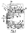
- Figure 2 is a cross-sectional view showing the body 10 of the device 1, integral with said electric rotor 9, which is rotatively driven through said electric stator 8, said electric rotor 9 and stator 8 forming together an electric motor.
- Figure 2 shows moreover in a very clear manner the arrangement of the threading tools 11 for threading, as desired, the free end portion of the bar 12.
- the refrigerating fluid 4, exiting the opening or outlet 5 of the supporting assembly 2, as is shown in figure 1 is not only used as a refrigerating fluid proper passing through the channels 6 of the annular body 7; in fact said refrigerating fluid 4, upon exiting the supporting assembly 2 through the channel 5, will moreover freely descend, to be also used as a refrigerating fluid for the machining tools 11 forming threads 13 on the free end portion of the bar 12 which threaded bar will be finally cut to any desired length.
- the fluid 4 will be filtered and fed again to the cooling channels 6.
- the rotary body 10 is very accurately supported on said supporting assembly 2 by precision bearings 14.
- the device 1 comprises an interface 20 to properly drive and control the motor 8, 9, which interface 20 is advantageously operatively coupled to a machine Numeric Control Device (not shown).
- Said interface is so pressurized as to prevent machining chips from depositing in the apparatus and wearing rotary parts of the latter.
- said single interface providing both a passage for the electric motor power supply cables and a pressurized operating environment, allows to make a compact and operatively flexible device, which can be easily and quickly supported by a slide of any desired single or multiple spindle machine tool without the need of modifying the latter.
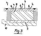
- Figure 3 shows a schematic cross-sectional view of the portion 10 of the supporting assembly 2, said portion 10 supporting not shown threading tools and comprising said electric rotor 9 forming, with said electric stator 8, a synchronous brushless electric motor 8, 9 (for example of a type offered and produced by the Company Phase Motion Control of Genoa).
- Figure 3 also clearly shows the circumferential channels 6 formed in the sleeve 7 therethrough said refrigerating fluid 4 supplied, for example, through a channel 3 of a central unit (not shown) flows, said fluid 4 being so temperature controlled as to properly cool said stator 8; moreover said fluid upon exiting the device 1 through the channel 5 ( figure 1 ) will be also conveyed to the machining tools 11 to also properly lubricate and cool the latter, and remove any machining chips from the resulting thread 13 at the free end portion of the bar 12.
- said refrigerating fluid 4 supplied, for example, through a channel 3 of a central unit (not shown) flows, said fluid 4 being so temperature controlled as to properly cool said stator 8; moreover said fluid upon exiting the device 1 through the channel 5 ( figure 1 ) will be also conveyed to the machining tools 11 to also properly lubricate and cool the latter, and remove any machining chips from the resulting thread 13 at the free end portion of the bar 12.
- the reference number 21 shows the fixed portion and the reference number 22 the rotary portion of a speed sensor for sensing the rotary speed of the body 10.
Landscapes
- Health & Medical Sciences (AREA)
- Orthopedic Medicine & Surgery (AREA)
- Surgery (AREA)
- Engineering & Computer Science (AREA)
- Life Sciences & Earth Sciences (AREA)
- Medical Informatics (AREA)
- Public Health (AREA)
- Neurology (AREA)
- Biomedical Technology (AREA)
- Heart & Thoracic Surgery (AREA)
- Mechanical Engineering (AREA)
- Molecular Biology (AREA)
- Animal Behavior & Ethology (AREA)
- General Health & Medical Sciences (AREA)
- Nuclear Medicine, Radiotherapy & Molecular Imaging (AREA)
- Veterinary Medicine (AREA)
- Connection Of Motors, Electrical Generators, Mechanical Devices, And The Like (AREA)
- Transmission Devices (AREA)
- Dental Tools And Instruments Or Auxiliary Dental Instruments (AREA)
- Magnetic Bearings And Hydrostatic Bearings (AREA)
- Knitting Machines (AREA)
- Sewing Machines And Sewing (AREA)
Applications Claiming Priority (1)
| Application Number | Priority Date | Filing Date | Title |
|---|---|---|---|
| IT000860A ITMI20070860A1 (it) | 2007-04-26 | 2007-04-26 | Dispositivo per filettare su una macchina tornitrice a controllo numerico |
Publications (3)
| Publication Number | Publication Date |
|---|---|
| EP1985397A2 true EP1985397A2 (fr) | 2008-10-29 |
| EP1985397A3 EP1985397A3 (fr) | 2018-01-24 |
| EP1985397B1 EP1985397B1 (fr) | 2020-06-10 |
Family
ID=39503767
Family Applications (1)
| Application Number | Title | Priority Date | Filing Date |
|---|---|---|---|
| EP08007185.5A Active EP1985397B1 (fr) | 2007-04-26 | 2008-04-11 | Appareil à fileter sur une tour contrôlée numériquement |
Country Status (6)
| Country | Link |
|---|---|
| US (1) | US7958805B2 (fr) |
| EP (1) | EP1985397B1 (fr) |
| JP (1) | JP5416360B2 (fr) |
| CN (1) | CN101293291A (fr) |
| ES (1) | ES2813905T3 (fr) |
| IT (1) | ITMI20070860A1 (fr) |
Cited By (8)
| Publication number | Priority date | Publication date | Assignee | Title |
|---|---|---|---|---|
| EP2359969A1 (fr) * | 2010-02-16 | 2011-08-24 | Reika GmbH & Co. KG | Dispositif de séparation tourbillonant |
| EP2444186A1 (fr) * | 2010-10-20 | 2012-04-25 | Reika GmbH & Co. KG | Dispositif de séparation de colonne |
| DE102011082903A1 (de) | 2011-09-18 | 2013-03-21 | Gildemeister Italiana S.P.A. | Gewindewirbelvorrichtung und Drehmaschine umfassend eine Gewindewirbelvorrichtung |
| US10239140B2 (en) | 2010-08-16 | 2019-03-26 | Emerson Electric Co. | Systems and devices for performing powered threading operations |
| WO2019097074A1 (fr) * | 2017-11-20 | 2019-05-23 | Hartmetall-Werkzeugfabrik Paul Horn Gmbh | Outil de filetage à la volée |
| EP3498408A1 (fr) * | 2017-12-14 | 2019-06-19 | Mirko Flam | Dispositif de tourbillonnage, logement d'outil et dispositif de transmission d'un fluide |
| CN110893492A (zh) * | 2019-12-03 | 2020-03-20 | 磐安艾肯机械设备有限公司 | 一种高效率齿条切割装置 |
| EP3852659A1 (fr) * | 2018-09-21 | 2021-07-28 | DePuy Synthes Products, Inc. | Vis à os de compression et procédés et systèmes associés |
Families Citing this family (5)
| Publication number | Priority date | Publication date | Assignee | Title |
|---|---|---|---|---|
| DE102009059707B4 (de) * | 2009-12-18 | 2021-10-28 | Wto Werkzeug-Einrichtungen Gmbh | Vorrichtung zum Gewindewirbeln und Werkzeug zur Montage eines Wirbelrings |
| CN102389985A (zh) * | 2010-12-11 | 2012-03-28 | 西安合升动力科技有限公司 | 用于刚性攻丝的交流永磁同步电主轴 |
| US12138702B2 (en) | 2019-11-01 | 2024-11-12 | Milwaukee Electric Tool Corporation | Portable pipe threader |
| EP4051447A4 (fr) | 2019-11-01 | 2024-04-03 | Milwaukee Electric Tool Corporation | Fileteuse de tuyaux portative |
| US12390870B2 (en) | 2021-03-31 | 2025-08-19 | Milwaukee Electric Tool Corporation | Lubrication system for portable pipe threader |
Family Cites Families (17)
| Publication number | Priority date | Publication date | Assignee | Title |
|---|---|---|---|---|
| US2036821A (en) * | 1935-11-07 | 1936-04-07 | Gen Electric | Machine tool driving system |
| FR1176722A (fr) * | 1956-06-16 | 1959-04-15 | Stahlkontor Weser G M B H Masc | Appareil à fraiser les filetages |
| US2934689A (en) * | 1957-11-22 | 1960-04-26 | Gen Precision Inc | Servo systems and quadrature signal filter therefor |
| US3129592A (en) * | 1958-11-10 | 1964-04-21 | Maxson Electronics Corp | Inertial integrating accelerometers |
| JPS5192789U (fr) * | 1975-01-24 | 1976-07-24 | ||
| AU521673B2 (en) * | 1980-01-16 | 1982-04-22 | Helmut Herdegen | Toolpost milling-attachment |
| JPS63257487A (ja) * | 1987-04-10 | 1988-10-25 | Fanuc Ltd | サ−ボモ−タの制御方法 |
| DE29507871U1 (de) * | 1995-05-12 | 1995-07-27 | Hermann Pfauter GmbH & Co., 71636 Ludwigsburg | Wälzfräsmaschine |
| US5664470A (en) * | 1996-05-06 | 1997-09-09 | The Olofsson Corporation | Tool turret indexer |
| JP3773316B2 (ja) * | 1996-07-18 | 2006-05-10 | 森精機興産株式会社 | 工作機械における切削油剤による主軸装置の冷却方法及び主軸冷却装置 |
| JP3387339B2 (ja) * | 1996-12-27 | 2003-03-17 | 住友金属工業株式会社 | ねじ切り機 |
| FR2758488B1 (fr) * | 1997-01-20 | 1999-02-12 | Jean Michel Delacou | Dispositif d'usinage par enlevement de copeaux, a bloc massif et colonne coulissante et machine incorporant ce dispositif |
| DE19918082B4 (de) * | 1999-04-21 | 2005-09-08 | Deckel Maho Gmbh | Universal-Werkzeugmaschine |
| JP2001252825A (ja) * | 2000-03-08 | 2001-09-18 | Toyoda Mach Works Ltd | 多軸タップ加工装置 |
| DE10125722A1 (de) * | 2001-05-18 | 2002-12-05 | Sauter Kg Feinmechanik | Werkzeugrevolver |
| JP4636824B2 (ja) * | 2004-07-14 | 2011-02-23 | 株式会社牧野フライス製作所 | 回転軸装置 |
| JP2006102906A (ja) * | 2004-10-08 | 2006-04-20 | Nsk Ltd | 主軸装置 |
-
2007
- 2007-04-26 IT IT000860A patent/ITMI20070860A1/it unknown
-
2008
- 2008-04-11 ES ES08007185T patent/ES2813905T3/es active Active
- 2008-04-11 EP EP08007185.5A patent/EP1985397B1/fr active Active
- 2008-04-21 JP JP2008109824A patent/JP5416360B2/ja active Active
- 2008-04-23 US US12/148,839 patent/US7958805B2/en active Active
- 2008-04-24 CN CNA2008100949069A patent/CN101293291A/zh active Pending
Cited By (15)
| Publication number | Priority date | Publication date | Assignee | Title |
|---|---|---|---|---|
| EP2359969A1 (fr) * | 2010-02-16 | 2011-08-24 | Reika GmbH & Co. KG | Dispositif de séparation tourbillonant |
| EP2605879B1 (fr) * | 2010-08-16 | 2019-08-07 | Emerson Electric Co. | Dispositif de réalisation d'opérations de filetage mécaniques et procédé s'y rapportant |
| US10668548B2 (en) | 2010-08-16 | 2020-06-02 | Emerson Electric Co. | Systems and devices for performing powered threading operations |
| EP3584027A1 (fr) * | 2010-08-16 | 2019-12-25 | Emerson Electric Co. | Dispositif de réalisation d'opérations de filetage mécaniques et procédé s'y rapportant |
| US10239140B2 (en) | 2010-08-16 | 2019-03-26 | Emerson Electric Co. | Systems and devices for performing powered threading operations |
| EP2444186A1 (fr) * | 2010-10-20 | 2012-04-25 | Reika GmbH & Co. KG | Dispositif de séparation de colonne |
| WO2013038028A1 (fr) | 2011-09-18 | 2013-03-21 | Gildemeister Italiana S.P.A. | Dispositif de filetage à la volée, et tour comprenant un dispositif de filetage à la volée |
| US9085031B2 (en) | 2011-09-18 | 2015-07-21 | Gildemeister Italiana S.P.A. | Thread whirling device and turning machine comprising a thread whirling device |
| DE102011082903A1 (de) | 2011-09-18 | 2013-03-21 | Gildemeister Italiana S.P.A. | Gewindewirbelvorrichtung und Drehmaschine umfassend eine Gewindewirbelvorrichtung |
| WO2019097074A1 (fr) * | 2017-11-20 | 2019-05-23 | Hartmetall-Werkzeugfabrik Paul Horn Gmbh | Outil de filetage à la volée |
| US11517967B2 (en) | 2017-11-20 | 2022-12-06 | Hartmetall-Werkzeugfabrik Paul Horn Gmbh | Whirling tool |
| EP3498408A1 (fr) * | 2017-12-14 | 2019-06-19 | Mirko Flam | Dispositif de tourbillonnage, logement d'outil et dispositif de transmission d'un fluide |
| EP3852659A1 (fr) * | 2018-09-21 | 2021-07-28 | DePuy Synthes Products, Inc. | Vis à os de compression et procédés et systèmes associés |
| CN110893492A (zh) * | 2019-12-03 | 2020-03-20 | 磐安艾肯机械设备有限公司 | 一种高效率齿条切割装置 |
| CN110893492B (zh) * | 2019-12-03 | 2021-02-02 | 江苏锦上精密齿条制造有限公司 | 一种高效率齿条切割装置 |
Also Published As
| Publication number | Publication date |
|---|---|
| ES2813905T3 (es) | 2021-03-25 |
| ITMI20070860A1 (it) | 2008-10-27 |
| CN101293291A (zh) | 2008-10-29 |
| JP2008272926A (ja) | 2008-11-13 |
| JP5416360B2 (ja) | 2014-02-12 |
| EP1985397B1 (fr) | 2020-06-10 |
| EP1985397A3 (fr) | 2018-01-24 |
| US20080264220A1 (en) | 2008-10-30 |
| US7958805B2 (en) | 2011-06-14 |
Similar Documents
| Publication | Publication Date | Title |
|---|---|---|
| EP1985397B1 (fr) | Appareil à fileter sur une tour contrôlée numériquement | |
| US20080131224A1 (en) | Whirling head and its use | |
| US11219977B2 (en) | Machine tool, in particular for drilling | |
| KR100997578B1 (ko) | 공구와 공구홀더 및 공작기계 | |
| CN112584972A (zh) | 多轴线旋转的动态冷却剂输送系统 | |
| KR100745933B1 (ko) | 공구와 공구홀더 및 공작기계 | |
| KR20030031870A (ko) | 공작기계의 장착부 및 공작기계 | |
| US7290316B2 (en) | Automatic screw machine with multi-axis drive control | |
| US9248505B2 (en) | Boring and facing head | |
| JP2020148300A (ja) | 静圧流体軸受装置 | |
| JPH10180543A (ja) | ねじ切り機 | |
| US12454008B2 (en) | Peeling machine for elongated products | |
| KR20220133093A (ko) | 선반 | |
| WO2008087502A1 (fr) | Ensemble pour finition d'une surface tridimensionnelle d'une pièce et machine comprenant un tel ensemble | |
| CN119839330B (zh) | 大孔径数控深孔变径镗刀及异型深孔加工方法 | |
| CN215393776U (zh) | 一种钢制品切割加工用数控机床 | |
| CN118023635B (zh) | 一种铆螺母攻丝机 | |
| CN105234442B (zh) | 用于加工内孔的刀具和系统 | |
| US20240075536A1 (en) | Tool driving device and method of producing hole processed product | |
| JP3473147B2 (ja) | スクリューロータの加工装置およびその加工方法 | |
| JP3958029B2 (ja) | 工具、工具ホルダおよび工作機械 | |
| JP2003145380A (ja) | 工具、工具ホルダおよび工作機械 | |
| JP2024173714A (ja) | タッピングマシンおよびタッピング方法 | |
| CN209021265U (zh) | 一种数控高精度自动钻孔机床 | |
| JP2024035338A (ja) | 工具駆動装置及び切削加工品の製造方法 |
Legal Events
| Date | Code | Title | Description |
|---|---|---|---|
| PUAI | Public reference made under article 153(3) epc to a published international application that has entered the european phase |
Free format text: ORIGINAL CODE: 0009012 |
|
| AK | Designated contracting states |
Kind code of ref document: A2 Designated state(s): AT BE BG CH CY CZ DE DK EE ES FI FR GB GR HR HU IE IS IT LI LT LU LV MC MT NL NO PL PT RO SE SI SK TR |
|
| AX | Request for extension of the european patent |
Extension state: AL BA MK RS |
|
| 17P | Request for examination filed |
Effective date: 20090203 |
|
| PUAL | Search report despatched |
Free format text: ORIGINAL CODE: 0009013 |
|
| AK | Designated contracting states |
Kind code of ref document: A3 Designated state(s): AT BE BG CH CY CZ DE DK EE ES FI FR GB GR HR HU IE IS IT LI LT LU LV MC MT NL NO PL PT RO SE SI SK TR |
|
| AX | Request for extension of the european patent |
Extension state: AL BA MK RS |
|
| RIC1 | Information provided on ipc code assigned before grant |
Ipc: A61B 17/86 20060101ALI20171218BHEP Ipc: B23B 5/46 20060101ALI20171218BHEP Ipc: B23G 1/34 20060101AFI20171218BHEP Ipc: B23Q 11/10 20060101ALI20171218BHEP Ipc: B23B 3/24 20060101ALI20171218BHEP |
|
| AKX | Designation fees paid |
Designated state(s): CH DE ES FR GB LI |
|
| AXX | Extension fees paid |
Extension state: MK Extension state: BA Extension state: RS Extension state: AL |
|
| STAA | Information on the status of an ep patent application or granted ep patent |
Free format text: STATUS: EXAMINATION IS IN PROGRESS |
|
| 17Q | First examination report despatched |
Effective date: 20190402 |
|
| GRAP | Despatch of communication of intention to grant a patent |
Free format text: ORIGINAL CODE: EPIDOSNIGR1 |
|
| STAA | Information on the status of an ep patent application or granted ep patent |
Free format text: STATUS: GRANT OF PATENT IS INTENDED |
|
| INTG | Intention to grant announced |
Effective date: 20191126 |
|
| GRAS | Grant fee paid |
Free format text: ORIGINAL CODE: EPIDOSNIGR3 |
|
| GRAA | (expected) grant |
Free format text: ORIGINAL CODE: 0009210 |
|
| STAA | Information on the status of an ep patent application or granted ep patent |
Free format text: STATUS: THE PATENT HAS BEEN GRANTED |
|
| AK | Designated contracting states |
Kind code of ref document: B1 Designated state(s): CH DE ES FR GB LI |
|
| REG | Reference to a national code |
Ref country code: GB Ref legal event code: FG4D |
|
| REG | Reference to a national code |
Ref country code: CH Ref legal event code: EP |
|
| REG | Reference to a national code |
Ref country code: DE Ref legal event code: R096 Ref document number: 602008062828 Country of ref document: DE |
|
| REG | Reference to a national code |
Ref country code: DE Ref legal event code: R097 Ref document number: 602008062828 Country of ref document: DE |
|
| REG | Reference to a national code |
Ref country code: ES Ref legal event code: FG2A Ref document number: 2813905 Country of ref document: ES Kind code of ref document: T3 Effective date: 20210325 |
|
| PLBE | No opposition filed within time limit |
Free format text: ORIGINAL CODE: 0009261 |
|
| STAA | Information on the status of an ep patent application or granted ep patent |
Free format text: STATUS: NO OPPOSITION FILED WITHIN TIME LIMIT |
|
| 26N | No opposition filed |
Effective date: 20210311 |
|
| PGFP | Annual fee paid to national office [announced via postgrant information from national office to epo] |
Ref country code: GB Payment date: 20210422 Year of fee payment: 14 Ref country code: ES Payment date: 20210519 Year of fee payment: 14 |
|
| GBPC | Gb: european patent ceased through non-payment of renewal fee |
Effective date: 20220411 |
|
| PG25 | Lapsed in a contracting state [announced via postgrant information from national office to epo] |
Ref country code: GB Free format text: LAPSE BECAUSE OF NON-PAYMENT OF DUE FEES Effective date: 20220411 |
|
| REG | Reference to a national code |
Ref country code: ES Ref legal event code: FD2A Effective date: 20230529 |
|
| PG25 | Lapsed in a contracting state [announced via postgrant information from national office to epo] |
Ref country code: ES Free format text: LAPSE BECAUSE OF NON-PAYMENT OF DUE FEES Effective date: 20220412 |
|
| PGFP | Annual fee paid to national office [announced via postgrant information from national office to epo] |
Ref country code: DE Payment date: 20250430 Year of fee payment: 18 |
|
| PGFP | Annual fee paid to national office [announced via postgrant information from national office to epo] |
Ref country code: FR Payment date: 20250422 Year of fee payment: 18 |
|
| PGFP | Annual fee paid to national office [announced via postgrant information from national office to epo] |
Ref country code: CH Payment date: 20250501 Year of fee payment: 18 |