EP1985346A2 - Verdampfereinrichtung - Google Patents
Verdampfereinrichtung Download PDFInfo
- Publication number
- EP1985346A2 EP1985346A2 EP08153391A EP08153391A EP1985346A2 EP 1985346 A2 EP1985346 A2 EP 1985346A2 EP 08153391 A EP08153391 A EP 08153391A EP 08153391 A EP08153391 A EP 08153391A EP 1985346 A2 EP1985346 A2 EP 1985346A2
- Authority
- EP
- European Patent Office
- Prior art keywords
- fuel
- evaporator
- conveyor
- supply pipeline
- supply line
- Prior art date
- Legal status (The legal status is an assumption and is not a legal conclusion. Google has not performed a legal analysis and makes no representation as to the accuracy of the status listed.)
- Granted
Links
Images

Classifications
-
- B—PERFORMING OPERATIONS; TRANSPORTING
- B01—PHYSICAL OR CHEMICAL PROCESSES OR APPARATUS IN GENERAL
- B01B—BOILING; BOILING APPARATUS ; EVAPORATION; EVAPORATION APPARATUS
- B01B1/00—Boiling; Boiling apparatus for physical or chemical purposes ; Evaporation in general
- B01B1/005—Evaporation for physical or chemical purposes; Evaporation apparatus therefor, e.g. evaporation of liquids for gas phase reactions
-
- C—CHEMISTRY; METALLURGY
- C01—INORGANIC CHEMISTRY
- C01B—NON-METALLIC ELEMENTS; COMPOUNDS THEREOF; METALLOIDS OR COMPOUNDS THEREOF NOT COVERED BY SUBCLASS C01C
- C01B3/00—Hydrogen; Gaseous mixtures containing hydrogen; Separation of hydrogen from mixtures containing it; Purification of hydrogen; Reversible storage of hydrogen
- C01B3/02—Production of hydrogen; Production of gaseous mixtures containing hydrogen
- C01B3/32—Production of hydrogen; Production of gaseous mixtures containing hydrogen by reaction of gaseous or liquid organic compounds with gasifying agents, e.g. water, carbon dioxide or air
- C01B3/34—Production of hydrogen; Production of gaseous mixtures containing hydrogen by reaction of gaseous or liquid organic compounds with gasifying agents, e.g. water, carbon dioxide or air by reaction of hydrocarbons with gasifying agents
- C01B3/38—Production of hydrogen; Production of gaseous mixtures containing hydrogen by reaction of gaseous or liquid organic compounds with gasifying agents, e.g. water, carbon dioxide or air by reaction of hydrocarbons with gasifying agents using catalysts
- C01B3/386—Catalytic partial combustion
-
- H—ELECTRICITY
- H01—ELECTRIC ELEMENTS
- H01M—PROCESSES OR MEANS, e.g. BATTERIES, FOR THE DIRECT CONVERSION OF CHEMICAL ENERGY INTO ELECTRICAL ENERGY
- H01M8/00—Fuel cells; Manufacture thereof
- H01M8/06—Combination of fuel cells with means for production of reactants or for treatment of residues
- H01M8/0606—Combination of fuel cells with means for production of reactants or for treatment of residues with means for production of gaseous reactants
- H01M8/0612—Combination of fuel cells with means for production of reactants or for treatment of residues with means for production of gaseous reactants from carbon-containing material
- H01M8/0618—Reforming processes, e.g. autothermal, partial oxidation or steam reforming
-
- H—ELECTRICITY
- H01—ELECTRIC ELEMENTS
- H01M—PROCESSES OR MEANS, e.g. BATTERIES, FOR THE DIRECT CONVERSION OF CHEMICAL ENERGY INTO ELECTRICAL ENERGY
- H01M8/00—Fuel cells; Manufacture thereof
- H01M8/06—Combination of fuel cells with means for production of reactants or for treatment of residues
- H01M8/0606—Combination of fuel cells with means for production of reactants or for treatment of residues with means for production of gaseous reactants
- H01M8/0612—Combination of fuel cells with means for production of reactants or for treatment of residues with means for production of gaseous reactants from carbon-containing material
- H01M8/0625—Combination of fuel cells with means for production of reactants or for treatment of residues with means for production of gaseous reactants from carbon-containing material in a modular combined reactor/fuel cell structure
- H01M8/0631—Reactor construction specially adapted for combination reactor/fuel cell
-
- C—CHEMISTRY; METALLURGY
- C01—INORGANIC CHEMISTRY
- C01B—NON-METALLIC ELEMENTS; COMPOUNDS THEREOF; METALLOIDS OR COMPOUNDS THEREOF NOT COVERED BY SUBCLASS C01C
- C01B2203/00—Integrated processes for the production of hydrogen or synthesis gas
- C01B2203/02—Processes for making hydrogen or synthesis gas
- C01B2203/025—Processes for making hydrogen or synthesis gas containing a partial oxidation step
- C01B2203/0261—Processes for making hydrogen or synthesis gas containing a partial oxidation step containing a catalytic partial oxidation step [CPO]
-
- C—CHEMISTRY; METALLURGY
- C01—INORGANIC CHEMISTRY
- C01B—NON-METALLIC ELEMENTS; COMPOUNDS THEREOF; METALLOIDS OR COMPOUNDS THEREOF NOT COVERED BY SUBCLASS C01C
- C01B2203/00—Integrated processes for the production of hydrogen or synthesis gas
- C01B2203/06—Integration with other chemical processes
- C01B2203/066—Integration with other chemical processes with fuel cells
-
- C—CHEMISTRY; METALLURGY
- C01—INORGANIC CHEMISTRY
- C01B—NON-METALLIC ELEMENTS; COMPOUNDS THEREOF; METALLOIDS OR COMPOUNDS THEREOF NOT COVERED BY SUBCLASS C01C
- C01B2203/00—Integrated processes for the production of hydrogen or synthesis gas
- C01B2203/12—Feeding the process for making hydrogen or synthesis gas
- C01B2203/1288—Evaporation of one or more of the different feed components
-
- Y—GENERAL TAGGING OF NEW TECHNOLOGICAL DEVELOPMENTS; GENERAL TAGGING OF CROSS-SECTIONAL TECHNOLOGIES SPANNING OVER SEVERAL SECTIONS OF THE IPC; TECHNICAL SUBJECTS COVERED BY FORMER USPC CROSS-REFERENCE ART COLLECTIONS [XRACs] AND DIGESTS
- Y02—TECHNOLOGIES OR APPLICATIONS FOR MITIGATION OR ADAPTATION AGAINST CLIMATE CHANGE
- Y02E—REDUCTION OF GREENHOUSE GAS [GHG] EMISSIONS, RELATED TO ENERGY GENERATION, TRANSMISSION OR DISTRIBUTION
- Y02E60/00—Enabling technologies; Technologies with a potential or indirect contribution to GHG emissions mitigation
- Y02E60/30—Hydrogen technology
- Y02E60/50—Fuel cells
Definitions
- the present invention relates to an evaporator device for evaporating a liquid fuel, in particular for a reformer of a fuel cell system.
- the invention also relates to a reformer equipped with such an evaporator device and to a fuel cell system equipped with such an evaporator device.
- reformers that are used in a motor vehicle, for example as part of a fuel cell system
- the fuel which is already carried along in the vehicle to operate an internal combustion engine, for producing a reformate gas containing hydrogen gas.
- gasoline, diesel, natural gas, and biodiesel are suitable for use in a reformer.
- liquid fuels an inhomogeneous mixture formation between the vaporized fuel and the gaseous oxidizer, usually air, can often be observed.
- the known metering device for supplying fuel to a reformer, in particular a fuel cell system.
- the known metering device has a supply line connecting a fuel tank with a fuel inlet of the reformer for introducing liquid fuel into the reformer.
- a conveyor for driving the liquid fuel is arranged in this supply line.
- a metering valve for adjusting a flowing through the supply line from the metering valve to the reformer fuel flow is arranged in the supply line downstream of the conveyor.
- the known metering device also comprises a return line, which is connected on the input side between the conveyor and the pressure control valve to the supply line and the output side to the fuel tank.
- a pressure-holding valve for setting a predetermined or predeterminable pressure is arranged.
- a reformer for generating a reformate gas containing hydrogen gas in which a fuel connection is associated with an evaporator.
- the evaporator consists essentially of a porous evaporator structure, which may be formed for example by nonwoven material or other tissue or mat-like fabric, foam, ceramic or the like.
- the fuel is introduced via a corresponding feed directly into the evaporator structure, in which the liquid fuel by capillary action large volume spreads. As a result, its surface extremely increases, which favors the evaporation of fuel.
- the present invention is concerned with the problem of providing an improved embodiment for an evaporator device or for a reformer equipped therewith or for a fuel cell system equipped therewith, which is characterized in particular by a homogeneous mixture formation.
- the invention is based on the general idea to provide an evaporator device which operates with a porous evaporator structure and a metering device, which makes it possible to selectively introduce a desired fuel flow in the evaporator structure.
- the porous evaporator structure used in this case can basically from the aforementioned DE 102 17 675 A1 correspond to known evaporator structure. Accordingly, the disclosure of this document is added by expressly referring to the disclosure of the present invention.
- a metering device can in principle be used a metering device, as for example from the aforementioned DE 100 20 089 A1 Accordingly, the disclosure of which is hereby incorporated by express reference into the disclosure content of the present invention becomes.
- the known metering device is equipped with at least one bubble separator for removing bubbles from the liquid fuel delivered in the supply line.
- This is arranged for this purpose in the supply line upstream of the conveyor.
- the invention uses the knowledge that bubbles in the liquid fuel hinder the homogeneous mixture formation. It has been found that the removal of bubbles from the fuel leads to a more uniform delivery of the conveyor and thus to a more uniform introduction of fuel into the evaporator structure, which favors overall continuous evaporation and the formation of a homogeneous mixture.
- the invention is of particular interest when the liquid fuel used is a comparatively volatile fuel, that is to say a fuel having a comparatively low vaporization temperature, e.g. Petrol.
- At least one vibration damper can be arranged in the supply line or in the return line. This design supports the accuracy of the fuel metering with the aid of the metering valve.
- Corresponding Fig. 1 comprises a fuel cell system 1, which may be preferably arranged in a motor vehicle, at least one fuel cell 2 and a reformer 3.
- the fuel cell 2 is used in a conventional manner for generating electricity from a fuel gas containing hydrogen gas and an oxidant gas containing oxygen gas.
- the fuel gas is supplied to an anode side 4 of the fuel cell 2, while the oxidizer gas, which is expediently air, a cathode side 5 of the fuel cell 2 is supplied.
- an electrolyte 6 separates the anode side 4 from the cathode side 5.
- the fuel cell 2 usually consists of a stack of several fuel cell elements, in each of which the anode side 4 is separated from the cathode side 5 by an electrolyte 6.
- the fuel cell is a high-temperature fuel cell, which may be configured in particular as a solid-state fuel cell or as an SOFC fuel cell.
- the fuel cell 2 it is basically possible to design the fuel cell 2 as a low-temperature fuel cell, which may be in particular a PEM fuel cell, which operates with a proton transport membrane or with a polymer electrolyte membrane as the electrolyte 6.
- a CO cleaning device not shown here, may additionally be provided between reformer 3 and fuel cell 2.
- the fuel cell 2 On the input side, the fuel cell 2 receives an anode gas formed by the fuel gas via an anode gas line 7 connected to the anode side 4. An anode exhaust gas containing hydrogen gas leaves the fuel cell 2 on the output side via an anode exhaust gas line 8, which is likewise connected to the anode side 4. Furthermore, the fuel cell 2 receives on the input side via a cathode gas line 9 connected to the cathode side 5 a cathode gas formed by the oxidizer gas. A cathode exhaust gas leaves the fuel cell 2 on the output side via a cathode exhaust gas line 10, which is connected to the cathode side 5 for this purpose.
- the fuel cell system 1 is expediently equipped with an oxidizer supply device 11 which is designed to supply oxidizer gas, that is to say in particular air, to at least one component of the fuel cell system 1.
- an oxidizer supply device 11 which is designed to supply oxidizer gas, that is to say in particular air, to at least one component of the fuel cell system 1.
- it has a supply line 12, in which a suitable conveyor 13, e.g. a pump or a blower arranged to drive the oxidizer gas.
- the supply line 12 can be connected to the respective component of the fuel cell system 1 to be supplied with oxidizer gas directly or, as here, via a corresponding supply line branch.
- three such supply line branches are provided, namely a first supply line branch 14, a second supply line branch 15 and a third supply line branch 16.
- the first supply line branch 14 forms the cathode gas line 9 and supplies the oxidizer gas to the fuel cell 2.
- a valve device 20 may be provided which is selectively actuated via a corresponding, not shown here control that the respectively required Oxidatorgasmenge by the respective supply line branch 14, 15, 16 is conveyed.
- the reformer 3 serves to generate the fuel gas from a liquid fuel and from an oxidizer gas, preferably air.
- the reformer 3 is connected on the input side to a fuel line 17 and to an oxidizer line 18.
- a conveyor 19 for driving the fuel is arranged, e.g. a pump.
- the fuel is an atomic hydrogen-containing liquid fuel, preferably a hydrocarbon.
- the oxidizer line 18 supplies the oxidizer gas to the reformer 3 and, in the example shown, is formed by the second supply line branch 15.
- the fuel cell system 1 can also have a residual gas burner 21, which is designed for burning anode exhaust gas with cathode exhaust gas.
- the residual gas burner 21 is connected on the input side to the anode exhaust gas line 8 and to the cathode exhaust gas line 10.
- the residual gas burner 21 is equipped with a combustion chamber 22 in which a combustion reaction takes place with an open flame.
- a residual gas burner 21 is also conceivable, which has an oxidation catalyst and works with catalytic combustion.
- an exhaust gas line 23 is connected to the residual gas burner 21, via which a burner exhaust gas formed by the combustion reaction is discharged from the residual gas burner 21.
- a cooling gas line 24 may be connected to the residual gas burner 21, in particular on the cathode side. If necessary, a cooling gas, preferably air, can be fed to the residual gas burner 21 via the cooling gas line 24.
- the cooling gas line 24 is formed by the third supply line branch 16.
- the Oxidator machines worn 11 is used to supply the fuel cell 2 of the reformer 3 and the residual gas burner 21 with oxidizer gas.
- the Oxidatorchucks worn 11 may also be configured so that it supplies only one of these components 2, 3, 21 or only two of these components 2, 3, 21 with the oxidant gas.
- at least one further oxidator supply device can then be provided.
- the fuel cell system 1 may further comprise at least one heat exchanger.
- four heat exchangers are provided, namely a main heat exchanger 25, a Rezirkulationskorübertrager 27 and an auxiliary heat exchanger 28.
- the main heat exchanger 25 is on the one hand in the exhaust pipe 23 and on the other hand integrated into the cathode gas line 9 and in the first supply line branch 14 and thus serves for the transmission of Heat from the burner exhaust gas to the cathode gas.
- the recirculation heat exchanger 27 is on the one hand in the Oxidatorgastechnisch 18 or in the second supply line branch 15 and on the other hand incorporated into a recirculation line 29.
- This recirculation line 29 branches off at 30 from the anode exhaust gas line 8 and is connected to the input side of the reformer 3. It contains downstream of the Rezirkulations Scriübertragers 27, a conveyor 31 for driving the recirculated anode exhaust gas, which may be, for example, a pump, a blower or a compressor. Depending on the operating state of the fuel cell 2, the anode exhaust gas can contain a relatively high proportion of hydrogen gas and can thus be utilized by the return to the reformer 3 to increase the efficiency. Finally, the auxiliary heat exchanger 28 is integrated on the one hand into the exhaust pipe 23 and on the other hand into a line 32, which can lead to a basically any heat consumer.
- the auxiliary heat exchanger 28 may be integrated via the line 32 into a cooling circuit of an internal combustion engine of the motor vehicle equipped with the fuel cell system 1 or into a heating circuit for warming up a vehicle interior of the vehicle equipped with the fuel cell system 1.
- the auxiliary heat exchanger 28 is arranged in the exhaust pipe 23 downstream of the main heat exchanger 25 and can extract additional heat from the burner exhaust gas.
- Fuel cell 2 residual gas burner 21, main heat exchanger 25, Rezirkulationskorübertrager 27 and auxiliary heat exchanger 28 form in the examples shown, each separate components. In principle, however, it is possible, at least structurally integrating two of these components into one unit.
- the residual gas burner 21 can be integrated into an output side of the fuel cell 2.
- the main heat exchanger 25 can be integrated into the outlet side of the residual gas burner 21. It is also possible to integrate two or more heat exchangers 25, 27, 28 to form a structural unit.
- the fuel cell system 1 here also has a thermally insulating insulating sheath 33, which is indicated by a broken line. It consists of a thermally insulating material.
- the fuel cell 2, the reformer 3, the residual gas burner 21 and the main heat exchanger 25 are enveloped by the insulating sheath 33, while the recirculation heat exchanger 27 with the associated conveyor 31 and the auxiliary heat exchanger 28 and parts of the Oxidatorchucks adopted 11 are disposed outside the insulation sheath 33.
- the insulation sheath 33 consists of several partial sheaths.
- the fuel line 17 can be connected directly to the reformer 3; the insulation sheath 33 may have a corresponding recess there. In this way, it is avoided to lay the fuel line 17 within the insulation sheath 33.
- the reformer 3 contains a mixture-forming section 34 and a reactor section 35.
- the mixture-forming section 34 the most homogeneous possible mixture of vaporized fuel and oxidizer gas and optionally recycled anode exhaust gas is formed. This mixture is supplied to the reactor section 35.
- the reactor section 35 the generation of the reformate gas or fuel gas or anode gas takes place.
- the reactor section 35 operates, for example, with partial oxidation and may contain a corresponding catalyst for this purpose.
- the fuel cell system 1 has an evaporator device 36, which in Fig. 1 is indicated by a drawn with a broken line frame.
- the evaporator device 36 may form part of the reformer 3 and in particular the fuel line 17 and the associated conveyor 19 include.
- such an evaporator device 36 includes a porous evaporator structure 37 configured to more easily vaporize a liquid fuel introduced therein.
- the evaporator structure 37 causes fuel introduced therein to spread in the volume of the evaporator structure 37, in particular due to capillary forces, thereby greatly increasing its surface area available for evaporation.
- the evaporator device 36 also includes a supply line 38, which corresponds to the fuel line 17. Accordingly, the evaporator device 36 includes those in the supply line
- the supply line 38 connects a fuel tank 39 to the evaporator structure 37.
- the supply line 38 is designed such that it introduces the liquid fuel directly into the evaporator structure 37.
- the feed line 38 preferably ends directly at or in the evaporator structure 37.
- the evaporator device 36 also includes a metering valve 40 which is disposed in the supply line 38 downstream of the conveyor 19.
- the metering valve 40 is designed such that a flow of fuel flowing through the supply line 38 from the metering valve 40 to the evaporator structure 37 is adjustable.
- the evaporator device 36 comprises a return line 41. This is the input side connected between the conveyor 19 and the metering valve 40 to the supply line 38 and the output side to the fuel tank 39.
- a connection point or connection point between the supply line 38 and the return line 41 is designated 42 here.
- a check valve 26 may be arranged in the supply line 38, with which the supply line 38 is blocked and the metering valve 40 can be relieved.
- the evaporator device 36 also has at least one bubble separator 43.
- the bubble separators 43 are preferably arranged in series, so that they are flowed through by the entire fuel flow in succession.
- the respective bubble separator 43 is expediently arranged upstream of the delivery device 19 in the supply line 38 and is in each case designed such that it can remove bubbles from the liquid fuel conveyed in the supply line 38.
- the separated bubbles can then be returned to the fuel tank 39 via a corresponding return 44. If a plurality of bubble separators 43 are provided, it may be expedient to provide a common return 44 for them.
- the supply line 38 is connected to a lower side 45 arranged in the installed state bottom, while the return line 41 is connected to a top in the installed state top 46 of the fuel tank 39 to this.
- the return 44 is suitably connected to the top of the fuel tank 39, preferably in the fuel vapor region.
- a pressure holding valve 47 is preferably arranged, which is designed so that so that a predetermined or a predeterminable pressure in the fuel upstream of the pressure holding valve 47 is adjustable.
- a pressure sensor 48 may be connected to the return line 41 to measure the pressure set in the fuel from the pressure holding valve 47 upstream of the pressure holding valve 47.
- a closed loop to set a desired pressure can be realized.
- a non-return valve 49 is optionally arranged in the supply line 38 between the conveyor 19 and the junction 42 of the return line 41.
- the check valve 49 locks in the direction of the conveyor 19.
- the conveyor 19 has a gear pump or is formed by a gear pump.
- the vaporizer device 36 may also be equipped with at least one vibration damper 50 that is configured to dampen pressure oscillations in the fuel.
- a vibration damper 50 is arranged here in the return line 41 upstream of the pressure-maintaining valve 47.
- such a vibration damper 50 may additionally or alternatively be arranged in the supply line 38, specifically downstream of the delivery device 19 and upstream of the metering valve 40.
- the evaporator structure 37 may include or be formed by a nonwoven material. Likewise, the evaporator structure 37 may comprise or be formed by a metal foam or a ceramic foam or a fabric or a mat.
Landscapes
- Chemical & Material Sciences (AREA)
- Chemical Kinetics & Catalysis (AREA)
- Engineering & Computer Science (AREA)
- Manufacturing & Machinery (AREA)
- Organic Chemistry (AREA)
- Life Sciences & Earth Sciences (AREA)
- Combustion & Propulsion (AREA)
- Sustainable Development (AREA)
- Sustainable Energy (AREA)
- Electrochemistry (AREA)
- General Chemical & Material Sciences (AREA)
- Health & Medical Sciences (AREA)
- General Health & Medical Sciences (AREA)
- Inorganic Chemistry (AREA)
- Fuel Cell (AREA)
Abstract
Description
- Die vorliegende Erfindung betrifft eine Verdampfereinrichtung zum Verdampfen eines flüssigen Kraftstoffs, insbesondere für einen Reformer eines Brennstoffzellensystems. Die Erfindung betrifft außerdem einen mit einer derartigen Verdampfereinrichtung ausgestatteten Reformer sowie ein mit einer derartigen Verdampfereinrichtung ausgestattetes Brennstoffzellensystem.
- Bei Reformern, die in einem Kraftfahrzeug zum Einsatz kommen, z.B. als Bestandteil eines Brennstoffzellensystems, bietet es sich an, den im Fahrzeug zum Betreiben einer Brennkraftmaschine ohnehin mitgeführten Kraftstoff zum Herstellen eines Wasserstoffgas enthaltenden Reformatgases zu verwenden. Beispielsweise eignen sich ohne Beschränkung der Allgemeinheit Benzin, Diesel, Erdgas und Biodiesel zur Verwendung in einem Reformer. Bei flüssigen Kraftstoffen lässt sich häufig eine inhomogene Gemischbildung zwischen dem verdampften Kraftstoff und dem gasförmigen Oxidator, in der Regel Luft, beobachten.
- Aus der
DE 100 20 089 A1 ist es bekannt, zur Kraftstoffversorgung eines Reformers, insbesondere eines Brennstoffzellensystems, eine Dosiereinrichtung vorzusehen. Die bekannte Dosiereinrichtung weist eine einen Kraftstofftank mit einem Kraftstoffeinlass des Reformers verbindende Zuführleitung zum Einbringen von flüssigem Kraftstoff in den Reformer auf. In dieser Zuführleitung ist eine Fördereinrichtung zum Antreiben des flüssigen Kraftstoffs angeordnet. Außerdem ist in der Zuführleitung stromab der Fördereinrichtung ein Dosierventil zum Einstellen eines durch die Zuführleitung vom Dosierventil zum Reformer fließenden Kraftstoffstroms angeordnet. Die bekannte Dosiereinrichtung umfasst außerdem eine Rückführleitung, die eingangsseitig zwischen der Fördereinrichtung und dem Druckregelventil an die Zuführleitung und ausgangsseitig an den Kraftstofftank angeschlossen ist. Zusätzlich ist bei der bekannten Dosiereinrichtung in der Rückführleitung ein Druckhalteventil zum Einstellen eines vorbestimmten oder vorbestimmbaren Drucks angeordnet. - Aus der
DE 102 17 675 A1 ist ein Reformer zum Generieren eines Wasserstoffgas enthaltenden Reformatgases bekannt, bei dem einem Kraftstoffanschluss ein Verdampfer zugeordnet ist. Beim bekannten Reformer besteht der Verdampfer im wesentlichen aus einer porösen Verdampferstruktur, die beispielsweise durch Vliesmaterial oder sonstiges Gewebe oder mattenartiges Gewebe, Schaum, Keramik oder dgl. gebildet sein kann. Der Kraftstoff wird dabei über eine entsprechende Zuführeinrichtung unmittelbar in die Verdampferstruktur eingebracht, in der sich der flüssige Kraftstoff durch Kapillarwirkung großvolumig ausbreitet. Hierdurch vergrößert sich seine Oberfläche extrem, was die Kraftstoffverdampfung begünstigt. - Die vorliegende Erfindung beschäftigt sich mit dem Problem, für eine Verdampfereinrichtung bzw. für einen damit ausgestatteten Reformer bzw. für ein damit ausgestattetes Brennstoffzellensystem eine verbesserte Ausführungsform anzugeben, die sich insbesondere durch eine homogene Gemischbildung auszeichnet.
- Dieses Problem wird erfindungsgemäß durch die Gegenstände der unabhängigen Ansprüche gelöst. Vorteilhafte Ausführungsformen sind Gegenstand der abhängigen Ansprüche.
- Die Erfindung beruht auf dem allgemeinen Gedanken, eine Verdampfereinrichtung zu schaffen, die mit einer porösen Verdampferstruktur und einer Dosiereinrichtung arbeitet, die es ermöglicht, einen erwünschten Kraftstoffstrom gezielt in die Verdampferstruktur einzubringen. Die hierbei verwendete poröse Verdampferstruktur kann dabei grundsätzlich der aus der zuvor genannten
DE 102 17 675 A1 bekannten Verdampferstruktur entsprechen. Dementsprechend wird der Offenbarungsgehalt dieses Dokuments durch ausdrückliche Bezugnahme zum Offenbarungsgehalt der vorliegenden Erfindung hinzugefügt. Als Dosiereinrichtung kann grundsätzlich eine Dosiereinrichtung verwendet werden, wie sie beispielsweise aus der zuvor genanntenDE 100 20 089 A1 bekannt ist, deren Offenbarungsgehalt dementsprechend durch ausdrückliche Bezugnahme zum Offenbarungsgehalt der vorliegenden Erfindung hinzugefügt wird. Zusätzlich ist bei der Erfindung die an sich bekannte Dosiereinrichtung mit wenigstens einem Blasenabscheider zum Entfernen von Blasen aus dem in der Zuführleitung geförderten flüssigen Kraftstoff ausgestattet. Dieser ist hierzu in der Zuführleitung stromauf der Fördereinrichtung angeordnet. Die Erfindung nutzt hierbei die Erkenntnis, dass Blasen im flüssigen Kraftstoff die homogene Gemischbildung behindern. Es hat sich gezeigt, dass die Entfernung von Blasen aus dem Kraftstoff zu einer gleichmäßigeren Förderleistung der Fördereinrichtung und somit zu einer gleichmäßigeren Einleitung von Kraftstoff in die Verdampferstruktur führt, was insgesamt eine kontinuierliche Verdampfung und die Ausbildung eines homogenen Gemischs begünstigt. - Die Erfindung ist von besonderem Interesse, wenn es sich beim verwendeten flüssigen Kraftstoff um einen vergleichsweise flüchtigen Kraftstoff, also um einen Kraftstoff mit vergleichsweise niedriger Verdampfungstemperatur handelt, wie z.B. Benzin.
- Bei einer vorteilhaften Ausführungsform kann in der Zuführleitung bzw. in der Rückführleitung zumindest ein Schwingungsdämpfer angeordnet sein. Diese Bauweise unterstützt die Genauigkeit der Kraftstoffdosierung mit Hilfe des Dosierventils.
- Weitere wichtige Merkmale und Vorteile der Erfindung ergeben sich aus den Unteransprüchen, aus den Zeichnungen und aus der zugehörigen Figurenbeschreibung anhand der Zeichnungen. Es versteht sich, dass die vorstehend genannten und die nachstehend noch zu erläuternden Merkmale nicht nur in der jeweils angegebenen Kombination, sondern auch in anderen Kombinationen oder in Alleinstellung verwendbar sind, ohne den Rahmen der vorliegenden Erfindung zu verlassen.
- Bevorzugte Ausführungsbeispiele der Erfindung sind in den Zeichnungen dargestellt und werden in der nachfolgenden Beschreibung näher erläutert, wobei sich gleiche Bezugszeichen auf gleiche oder ähnliche oder funktional gleiche Bauteile beziehen.
- Es zeigen, jeweils schematisch,
- Fig. 1
- ein Brennstoffzellensystem mit einem Reformer und einer Verdampfereinrichtung,
- Fig. 2
- eine Verdampfereinrichtung.
- Entsprechend
Fig. 1 umfasst ein Brennstoffzellensystem 1, das vorzugsweise in einem Kraftfahrzeug angeordnet sein kann, zumindest eine Brennstoffzelle 2 sowie einen Reformer 3. Die Brennstoffzelle 2 dient in üblicher Weise zum Generieren von Strom aus einem Wasserstoffgas enthaltenden Brenngas und einem Sauerstoffgas enthaltenden Oxidatorgas. Das Brenngas wird dabei einer Anodenseite 4 der Brennstoffzelle 2 zugeführt, während das Oxidatorgas, bei dem es sich zweckmäßig um Luft handelt, einer Kathodenseite 5 der Brennstoffzelle 2 zugeführt wird. In der Brennstoffzelle 2 trennt ein Elektrolyt 6 die Anodenseite 4 von der Kathodenseite 5. Üblicherweise besteht die Brennstoffzelle 2 aus einem Stapel mehrerer Brennstoffzellenelemente, in denen jeweils die Anodenseite 4 durch einen Elektrolyten 6 von der Kathodenseite 5 getrennt ist. Vorzugsweise handelt es sich bei der Brennstoffzelle um eine Hochtemperatur-Brennstoffzelle, die insbesondere als Festkörper-Brennstoffzelle bzw. als SOFC-Brennstoffzelle ausgestaltet sein kann. Ebenso ist es grundsätzlich möglich, die Brennstoffzelle 2 als Niedertemperatur-Brennstoffzelle auszugestalten, die insbesondere eine PEM-Brennstoffzelle sein kann, die mit einer Protonen-Transport-Membran bzw. mit einer Polymer-Elektrolyt-Membran als Elektrolyt 6 arbeitet. Für diesen Fall kann zusätzlich eine hier nicht gezeigte CO-Reinigungseinrichtung zwischen Reformer 3 und Brennstoffzelle 2 vorgesehen sein. - Die Brennstoffzelle 2 erhält eingangsseitig über eine an die Anodenseite 4 angeschlossene Anodengasleitung 7 ein durch das Brenngas gebildetes Anodengas. Ein Wasserstoffgas enthaltendes Anodenabgas verlässt die Brennstoffzelle 2 ausgangsseitig über eine Anodenabgasleitung 8, die ebenfalls an die Anodenseite 4 angeschlossen ist. Des Weiteren erhält die Brennstoffzelle 2 eingangsseitig über eine an die Kathodenseite 5 angeschlossene Kathodengasleitung 9 ein durch das Oxidatorgas gebildetes Kathodengas. Ein Kathodenabgas verlässt die Brennstoffzelle 2 ausgangsseitig über eine Kathodenabgasleitung 10, die hierzu an die Kathodenseite 5 angeschlossen ist.
- Das Brennstoffzellensystem 1 ist zweckmäßig mit einer Oxidatorversorgungseinrichtung 11 ausgestattet, die zum Zuführen von Oxidatorgas, also insbesondere von Luft, zu wenigstens einer Komponente des Brennstoffzellensystems 1 ausgestaltet ist. Hierzu weist sie eine Versorgungsleitung 12 auf, in der eine geeignete Fördereinrichtung 13, z.B. eine Pumpe oder ein Gebläse, zum Antreiben des Oxidatorgases angeordnet ist. Die Versorgungsleitung 12 kann an die jeweilige mit Oxidatorgas zu versorgende Komponente des Brennstoffzellensystems 1 direkt oder - wie hier - über einen entsprechenden Versorgungsleitungszweig angeschlossen sein. Beim hier gezeigten Beispiel sind drei derartige Versorgungsleitungszweige vorgesehen, nämlich ein erster Versorgungsleitungszweig 14, ein zweiter Versorgungsleitungszweig 15 und ein dritter Versorgungsleitungszweig 16. Der erste Versorgungsleitungszweig 14 bildet die Kathodengasleitung 9 und führt das Oxidatorgas der Brennstoffzelle 2 zu.
- Zur gezielten Aufteilung des mit der Fördereinrichtung 13 geförderten Oxidatorgases von der gemeinsamen Versorgungsleitung 12 auf die einzelnen Versorgungsleitungszweige 14, 15, 16 kann eine Ventileinrichtung 20 vorgesehen sein, die über eine entsprechende, hier nicht dargestellte Steuerung gezielt so betätigbar ist, dass die jeweils erforderliche Oxidatorgasmenge durch den jeweiligen Versorgungsleitungszweig 14, 15, 16 förderbar ist.
- Der Reformer 3 dient zum Erzeugen des Brenngases aus einem flüssigen Kraftstoff und aus einem Oxidatorgas, vorzugsweise Luft. Hierzu ist der Reformer 3 eingangsseitig an eine Kraftstoffleitung 17 und an eine Oxidatorleitung 18 angeschlossen. In der Kraftstoffleitung 17 ist eine Fördereinrichtung 19 zum Antreiben des Kraftstoffs angeordnet, z.B. eine Pumpe. Beim Kraftstoff handelt es sich um einen atomaren Wasserstoff enthaltenden flüssigen Kraftstoff, vorzugsweise um einen Kohlenwasserstoff. Zweckmäßig kann dabei derjenige Kraftstoff verwendet werden, der in einem mit dem Brennstoffzellensystem 1 ausgestatteten Kraftfahrzeug ohnehin zum Betreiben einer Brennkraftmaschine des Fahrzeugs vorhanden ist, also insbesondere Benzin, Diesel, Biodiesel. Die Oxidatorleitung 18 führt dem Reformer 3 das Oxidatorgas zu und ist im gezeigten Beispiel durch den zweiten Versorgungsleitungszweig 15 gebildet.
- Das Brennstoffzellensystem 1 kann außerdem einen Restgasbrenner 21 aufweisen, der zum Verbrennen von Anodenabgas mit Kathodenabgas ausgestaltet ist. Hierzu ist der Restgasbrenner 21 eingangsseitig an die Anodenabgasleitung 8 und an die Kathodenabgasleitung 10 angeschlossen. Bevorzugt ist der Restgasbrenner 21 mit einem Brennraum 22 ausgestattet, in dem eine Verbrennungsreaktion mit offener Flamme abläuft. Grundsätzlich ist jedoch auch ein Restgasbrenner 21 denkbar, der einen Oxidationskatalysator aufweist und mit katalytischer Verbrennung arbeitet. Ausgangsseitig ist an den Restgasbrenner 21 eine Abgasleitung 23 angeschlossen, über die ein durch die Verbrennungsreaktion gebildetes Brennerabgas vom Restgasbrenner 21 abgeführt wird. Optional kann an den Restgasbrenner 21 eine Kühlgasleitung 24 angeschlossen sein, und zwar insbesondere kathodenseitig. Über die Kühlgasleitung 24 ist bei Bedarf ein Kühlgas, vorzugsweise Luft, dem Restgasbrenner 21 zuführbar. Im gezeigten Beispiel ist die Kühlgasleitung 24 durch den dritten Versorgungsleitungszweig 16 gebildet.
- Bei der hier gezeigten, bevorzugten Ausführungsform dient die Oxidatorversorgungseinrichtung 11 zur Versorgung der Brennstoffzelle 2 des Reformers 3 und des Restgasbrenners 21 mit Oxidatorgas. Bei einer anderen Ausführungsform kann die Oxidatorversorgungseinrichtung 11 auch so ausgestaltet sein, dass sie nur eine dieser Komponenten 2, 3, 21 oder nur zwei dieser Komponenten 2, 3, 21 mit dem Oxidatorgas versorgt. Zur Versorgung der jeweils anderen Komponente oder Komponenten 2, 3, 21 kann dann zumindest eine weitere Oxidatorversorgungseinrichtung vorgesehen sein.
- Das Brennstoffzellensystem 1 kann des Weiteren zumindest einen Wärmeübertrager aufweisen. Im gezeigten Beispiel sind vier Wärmeübertrager vorgesehen, nämlich ein Hauptwärmeübertrager 25, ein Rezirkulationswärmeübertrager 27 und ein Hilfswärmeübertrager 28. Der Hauptwärmeübertrager 25 ist einerseits in die Abgasleitung 23 und andererseits in die Kathodengasleitung 9 bzw. in den ersten Versorgungsleitungszweig 14 eingebunden und dient somit zur Übertragung von Wärme vom Brennerabgas auf das Kathodengas. Der Rezirkulationswärmeübertrager 27 ist einerseits in die Oxidatorgasleitung 18 bzw. in den zweiten Versorgungsleitungszweig 15 und andererseits in eine Rezirkulationsleitung 29 eingebunden. Diese Rezirkulationsleitung 29 zweigt bei 30 von der Anodenabgasleitung 8 ab und ist an die Eingangsseite des Reformers 3 angeschlossen. Sie enthält stromab des Rezirkulationswärmeübertragers 27 eine Fördereinrichtung 31 zum Antreiben des rezirkulierten Anodenabgases, bei der es sich beispielsweise um eine Pumpe, ein Gebläse oder einen Kompressor handeln kann. Das Anodenabgas kann je nach Betriebszustand der Brennstoffzelle 2 einen relativ hohen Anteil an Wasserstoffgas enthalten und kann somit durch die Rückführung in den Reformer 3 zur Steigerung des Wirkungsgrads genutzt werden. Schließlich ist der Hilfswärmeübertrager 28 einerseits in die Abgasleitung 23 und andererseits in eine Leitung 32 eingebunden, die zu einem grundsätzlich beliebigen Wärmeverbraucher führen kann. Insbesondere kann der Hilfswärmeübertrager 28 über die Leitung 32 in einen Kühlkreis einer Brennkraftmaschine des mit dem Brennstoffzellensystem 1 ausgestatteten Kraftfahrzeugs oder in einen Heizkreis zum Aufwärmen eines Fahrzeuginnenraums des mit dem Brennstoffzellensystem 1 ausgestatteten Fahrzeugs eingebunden sein. Der Hilfswärmeübertrager 28 ist in der Abgasleitung 23 stromab des Hauptwärmeübertragers 25 angeordnet und kann dem Brennerabgas zusätzliche Wärme entziehen.
- Brennstoffzelle 2, Restgasbrenner 21, Hauptwärmeübertrager 25, Rezirkulationswärmeübertrager 27 und Hilfswärmeübertrager 28 bilden in den gezeigten Beispielen jeweils separate Komponenten. Grundsätzlich ist es jedoch möglich, zumindest zwei dieser Komponenten baulich zu einer Einheit zu integrieren. Beispielsweise kann der Restgasbrenner 21 in eine Ausgangsseite der Brennstoffzelle 2 integriert werden. Zusätzlich oder alternativ kann der Hauptwärmeübertrager 25 in die Ausgangsseite des Restgasbrenners 21 integriert werden. Ebenso ist es möglich, zwei oder mehr Wärmeübertrager 25, 27, 28 zu einer baulichen Einheit zu integrieren.
- Das Brennstoffzellensystem 1 weist hier außerdem eine thermisch isolierende Isolationshülle 33 auf, die durch eine unterbrochene Linie angedeutet ist. Sie besteht aus einem thermisch isolierenden Material. Im gezeigten Beispiel sind von der Isolationshülle 33 die Brennstoffzelle 2, der Reformer 3, der Restgasbrenner 21 und der Hauptwärmeübertrager 25 umhüllt, während der Rezirkulationswärmeübertrager 27 mit der zugehörigen Fördereinrichtung 31 und der Hilfswärmeübertrager 28 sowie Teile der Oxidatorversorgungseinrichtung 11 außerhalb der Isolationshülle 33 angeordnet sind. Denkbar ist auch eine Ausführungsform, bei der die Isolationshülle 33 aus mehreren Teilhüllen besteht.
- Im Bereich der mit den entsprechenden Anschlüssen versehenen Eingangsseite des Reformers 3 ist die Kraftstoffleitung 17 direkt an den Reformer 3 anschließbar; die Isolationshülle 33 kann dort eine entsprechende Aussparung aufweisen. Auf diese Weise wird vermieden, die Kraftstoffleitung 17 innerhalb der Isolationshülle 33 zu verlegen.
- Der Reformer 3 enthält einen Gemischbildungsabschnitt 34 und einen Reaktorabschnitt 35. Im Gemischbildungsabschnitt 34 wird ein möglichst homogenes Gemisch aus verdampftem Kraftstoff und Oxidatorgas sowie ggf. rückgeführtem Anodenabgas gebildet. Dieses Gemisch wird dem Reaktorabschnitt 35 zugeführt. Im Reaktorabschnitt 35 erfolgt die Generierung des Reformatgases oder Brenngases oder Anodengases. Der Reaktorabschnitt 35 arbeitet beispielsweise mit partieller Oxidation und kann hierzu einen entsprechenden Katalysator enthalten. Zur Verdampfung des dem Reformer 3 in flüssigem Zustand zugeführten Kraftstoffs, bei dem es sich vorzugsweise um Benzin handelt, weist das Brennstoffzellensystem 1 eine Verdampfereinrichtung 36 auf, die in
Fig. 1 durch einen mit unterbrochener Linie gezeichneten Rahmen angedeutet ist. Die Verdampfereinrichtung 36 kann dabei einen Bestandteil des Reformers 3 bilden und insbesondere die Kraftstoffleitung 17 sowie die zugehörige Fördereinrichtung 19 beinhalten. - Entsprechend
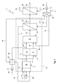
Fig. 2 umfasst eine derartige Verdampfereinrichtung 36 eine poröse Verdampferstruktur 37, die so ausgestaltet ist, dass ein darin eingebrachter flüssiger Kraftstoff leichter verdampft. Insbesondere bewirkt die Verdampferstruktur 37, dass sich darin eingeleiteter Kraftstoff, insbesondere aufgrund von Kapillarkräften, im Volumen der Verdampferstruktur 37 ausbreitet und dadurch seine für die Verdampfung bereitstehende Oberfläche extrem vergrößert. Die Verdampfereinrichtung 36 umfasst außerdem eine Zuführleitung 38, die der Kraftstoffleitung 17 entspricht. Dementsprechend umfasst die Verdampfereinrichtung 36 die in der Zuführleitung 38 angeordnete Fördereinrichtung 19. Die Zuführleitung 38 verbindet einen Kraftstofftank 39 mit der Verdampferstruktur 37. Die Zuführleitung 38 ist so ausgestaltet, dass sie den flüssigen Kraftstoff unmittelbar in die Verdampferstruktur 37 einbringt. Vorzugsweise endet die Zuführleitung 38 hierzu unmittelbar an oder in der Verdampferstruktur 37. - Die Verdampfereinrichtung 36 umfasst außerdem ein Dosierventil 40, das in der Zuführleitung 38 stromab der Fördereinrichtung 19 angeordnet ist. Das Dosierventil 40 ist so ausgestaltet, dass damit ein durch die Zuführleitung 38 vom Dosierventil 40 zur Verdampferstruktur 37 fließender Kraftstoffstrom einstellbar ist. Ferner umfasst die Verdampfereinrichtung 36 eine Rückführleitung 41. Diese ist eingangsseitig zwischen der Fördereinrichtung 19 und dem Dosierventil 40 an die Zuführleitung 38 und ausgangsseitig an den Kraftstofftank 39 angeschlossen. Eine Anschlussstelle oder Verbindungsstelle zwischen der Zuführleitung 38 und der Rückführleitung 41 ist hier mit 42 bezeichnet. Optional kann zwischen dem Dosierventil 40 und der Verbindungsstelle 42 ein Sperrventil 26 in der Zuführleitung 38 angeordnet sein, mit dem die Zuführleitung 38 gesperrt und das Dosierventil 40 entlastet werden kann.
- Die Verdampfereinrichtung 36 weist außerdem zumindest einen Blasenabscheider 43 auf. Im gezeigten Beispiel sind zwei derartige Blasenabscheider 43 vorgesehen. Bei anderen Ausführungsformen kann ein einzelner Blasenabscheider 43 ausreichen; ebenso können auch mehr als zwei Blasenabscheider 43 vorgesehen sein. Die Blasenabscheider 43 sind vorzugsweise in Reihe angeordnet, so dass sie vom gesamten Kraftstoffstrom nacheinander durchströmt werden. Der jeweilige Blasenabscheider 43 ist zweckmäßig stromauf der Fördereinrichtung 19 in der Zuführleitung 38 angeordnet und ist jeweils so ausgestaltet, dass er Blasen aus dem in der Zuführleitung 38 geförderten flüssigen Kraftstoff entfernen kann. Die abgeschiedenen Blasen können dann über einen entsprechenden Rücklauf 44 dem Kraftstofftank 39 rückgeführt werden. Sofern mehrere Blasenabscheider 43 vorgesehen sind, kann es zweckmäßig sein, für diese einen gemeinsamen Rücklauf 44 vorzusehen.
- Vorzugsweise ist die Zuführleitung 38 an einer im Einbauzustand unten angeordneten Unterseite 45 angeschlossen, während die Rücklaufleitung 41 an einer im Einbauzustand oben liegenden Oberseite 46 des Kraftstofftanks 39 an diesen angeschlossen ist. Auch der Rücklauf 44 ist zweckmäßig oben an den Kraftstofftank 39 angeschlossen, vorzugsweise im Kraftstoffdampfbereich.
- In der Rückführleitung 41 ist vorzugsweise ein Druckhalteventil 47 angeordnet, das so ausgestaltet ist, dass damit ein vorbestimmter oder ein vorbestimmbarer Druck im Kraftstoff stromauf des Druckhalteventils 47 einstellbar ist. Stromauf des Druckhalteventils 47 kann ein Drucksensor 48 an die Rückführleitung 41 angeschlossen sein, um den vom Druckhalteventil 47 eingestellten Druck im Kraftstoff stromauf des Druckhalteventils 47 zu messen. Insbesondere kann in Verbindung mit einem einstellbaren Druckhalteventil 47 ein geschlossener Regelkreis zum Einstellen eines gewünschten Drucks realisiert werden.
- Bei der hier gezeigten bevorzugten Ausführungsform ist optional zwischen der Fördereinrichtung 19 und der Anschlussstelle 42 der Rückführleitung 41 ein Rückschlagsperrventil 49 in der Zuführleitung 38 angeordnet. Das Rückschlagsperrventil 49 sperrt in Richtung zur Fördereinrichtung 19. Bei einer bevorzugten Ausführungsform weist die Fördereinrichtung 19 eine Zahnradpumpe auf oder ist durch eine Zahnradpumpe gebildet.
- Die Verdampfereinrichtung 36 kann außerdem mit wenigstens einem Schwingungsdämpfer 50 ausgestattet sein, der so ausgestaltet ist, dass er Druckschwingungen im Kraftstoff bedämpfen kann. Exemplarisch ist ein solcher Schwingungsdämpfer 50 hier in der Rückführleitung 41 stromauf des Druckhalteventils 47 angeordnet. Grundsätzlich kann ein derartiger Schwingungsdämpfer 50 zusätzlich oder alternativ in der Zuführleitung 38 angeordnet sein, und zwar stromab der Fördereinrichtung 19 und stromauf des Dosierventils 40.
- Die Verdampferstruktur 37 kann ein Vliesmaterial aufweisen oder dadurch gebildet sein. Ebenso kann die Verdampferstruktur 37 einen Metallschaum oder einen Keramikschaum oder ein Gewebe oder eine Matte aufweisen oder dadurch gebildet sein.
- Die Verdampfereinrichtung 36 arbeitet wie folgt:
- Bei eingeschalteter Verdampfereinrichtung 36 ist die Fördereinrichtung 19 in Betrieb, so dass diese Kraftstoff aus dem Kraftstofftank 39 ansaugt und in der Zuführleitung 38 fördert. Bei einer besonders einfachen Ausführungsform besitzt die Fördereinrichtung 19 nur eine einzige Betriebsstufe, in der sie zumindest so viel Kraftstoff fördert, wie der Reformer 3 bei maximaler Leistung benötigt. In Abhängigkeit eines aktuellen Kraftstoffbedarfs des Reformers 3 wird das Dosierventil 40 betätigt, um einen dem aktuellen Kraftstoffbedarf entsprechenden Kraftstoffstrom einzustellen. Der vom Dosierventil 40 eingestellte Kraftstoffstrom gelangt über die Zuführleitung 38 in flüssigem Zustand in die Verdampferstruktur 37 und kann dort im Gemischbildungsabschnitt 34 des Reformers 3 verdampfen und sich mit dem Oxidatorgas sowie ggf. mit dem rückgeführten Anodenabgas vermischen. Sofern der vom Dosierventil 40 eingestellte, dem Reformer 3 bzw. der Verdampferstruktur 37 zugeführte Kraftstoffstrom kleiner ist als die Fördermenge der Fördereinrichtung 19, wird die Differenz über die Rückführleitung 41 in den Tank 39 zurückgeführt. Das Druckhalteventil 47 sorgt dafür, dass die Fördereinrichtung 19 stromauf des Dosierventils 40 im Kraftstoff einen für eine ordnungsgemäße Dosierung oder Zumessung der jeweils gewünschten Kraftstoffmenge vorbestimmter Druck erzeugt. Die Blasenabscheider 43 reduzieren den Gasgehalt im Kraftstoff und bewirken bestenfalls, dass die Fördereinrichtung 19 blasenfreien Kraftstoff fördern kann. Durch das Ausscheiden der Blasen aus dem Kraftstoff kann die Fördereinrichtung 19, insbesondere wenn es sich dabei um eine Zahnradpumpe handelt, zuverlässiger arbeiten, um den gewünschten Druck im Kraftstoff und die gewünschte Fördermenge bereitzustellen. Dies führt zu einer verbesserten Verdampfung und Gemischbildung.
Claims (10)
- Verdampfereinrichtung zum Verdampfen eines flüssigen Kraftstoffs, insbesondere für einen Reformer (3) eines Brennstoffzellensystems (1),- mit einer porösen Verdampferstruktur (37) zum Verdampfen von in die Verdampferstruktur (37) eingebrachtem flüssigen Kraftstoff,- mit einer einen Kraftstofftank (39) mit der Verdampferstruktur (37) verbindenden Zuführleitung (38) zum Einbringen von flüssigem Kraftstoff in die Verdampferstruktur (37),- mit einer in der Zuführleitung (38) angeordneten Fördereinrichtung (19) zum Antreiben des flüssigen Kraftstoffs,- mit einem in der Zuführleitung (38) stromab der Fördereinrichtung (19) angeordneten Dosierventil (40) zum Einstellen eines durch die Zuführleitung (38) vom Dosierventil (40) zur Verdampferstruktur (37) fließenden Kraftstoffstroms,- mit einer Rückführleitung (41), die eingangsseitig zwischen der Fördereinrichtung (19) und dem Dosierventil (40) an die Zuführleitung (38) und ausgangsseitig an den Kraftstofftank (39) angeschlossen ist,- mit wenigstens einem in der Zuführleitung (38) stromauf der Fördereinrichtung (19) angeordneten Blasenabscheider (43) zum Entfernen von Blasen aus dem in der Zuführleitung (38) geförderten flüssigen Kraftstoff.
- Verdampfereinrichtung nach Anspruch 1,
dadurch gekennzeichnet,
dass in der Rückführleitung (41) ein Druckhalteventil (47) zum Einstellen eines vorbestimmten oder vorbestimmbaren Drucks angeordnet ist. - Verdampfereinrichtung nach Anspruch 1 oder 2,
dadurch gekennzeichnet,- dass zumindest zwei Blasenabscheider (43) in der Zuführleitung (38) stromauf der Fördereinrichtung (19) in Reihe angeordnet sind, und/oder- dass der jeweilige Blasenabscheider (43) über einen Rücklauf (44) mit dem Kraftstofftank (39) verbunden ist, und/oder- dass für zwei oder mehr Blasenabscheider (43) ein gemeinsamer Rücklauf (44) vorgesehen ist. - Verdampfereinrichtung nach einem der Ansprüche 1 bis 3,
dadurch gekennzeichnet,
dass in der Zuführleitung (38) zwischen der Fördereinrichtung (19) und einer Anschlussstelle (42) der Rückführleitung (41) ein zur Fördereinrichtung (19) hin sperrendes Rückschlagsperrventil (49) angeordnet ist. - Verdampfereinrichtung nach einem der Ansprüche 1 bis 4,
dadurch gekennzeichnet,
dass die Fördereinrichtung (19) eine Zahnradpumpe aufweist oder dadurch gebildet ist. - Verdampfereinrichtung nach einem der Ansprüche 1 bis 5,
dadurch gekennzeichnet,
dass die Verdampferstruktur (37) eine poröse Struktur zur Kraftstoffverteilung und Oberflächenvergrößerung ist und insbesondere ein Vliesmaterial oder einen Metallschaum oder einen Keramikschaum oder ein Gewebe oder eine Matte aufweist oder dadurch gebildet ist. - Verdampfereinrichtung nach einem der Ansprüche 1 bis 6,
dadurch gekennzeichnet,
dass die Zuführleitung (38) unmittelbar an oder in der Verdampferstruktur (37) endet. - Verdampfereinrichtung nach einem der Ansprüche 1 bis 7,
dadurch gekennzeichnet,
dass in der Zuführleitung (38) und/oder in der Rückführleitung (41) zumindest ein Schwingungsdämpfer (50) angeordnet ist, und zwar bevorzugt stromab der Fördereinrichtung (19) und/oder stromauf des Druckhalteventils (47) und/oder stromauf des Dosierventils (47). - Reformer zum Generieren eines Wasserstoffgas enthaltenden Reformatgases aus einem flüssigen Kraftstoff und einem Oxidator, insbesondere für ein Brennstoffzellensystem (1),
mit einer Verdampfereinrichtung (36) nach einem der Ansprüche 1 bis 8. - Brennstoffzellensystem, insbesondere in einem Kraftfahrzeug,- mit wenigstens einer Brennstoffzelle (2) zum Generieren von elektrischem Strom aus einem Wasserstoffgas enthaltenden Anodengas und einem Sauerstoffgas enthaltenden Kathodengas,- mit einem Reformer (3) zum Generieren des Anodengases aus einem flüssigen Kraftstoff und einem Oxidator,- mit einer dem Reformer (3) zugeordneten Verdampfereinrichtung (36) nach einem der Ansprüche 1 bis 8.
Applications Claiming Priority (1)
| Application Number | Priority Date | Filing Date | Title |
|---|---|---|---|
| DE102007019360A DE102007019360A1 (de) | 2007-04-23 | 2007-04-23 | Verdampfereinrichtung |
Publications (3)
| Publication Number | Publication Date |
|---|---|
| EP1985346A2 true EP1985346A2 (de) | 2008-10-29 |
| EP1985346A3 EP1985346A3 (de) | 2010-09-29 |
| EP1985346B1 EP1985346B1 (de) | 2011-12-21 |
Family
ID=39689251
Family Applications (1)
| Application Number | Title | Priority Date | Filing Date |
|---|---|---|---|
| EP08153391A Active EP1985346B1 (de) | 2007-04-23 | 2008-03-27 | Verdampfereinrichtung |
Country Status (3)
| Country | Link |
|---|---|
| EP (1) | EP1985346B1 (de) |
| AT (1) | ATE537888T1 (de) |
| DE (1) | DE102007019360A1 (de) |
Cited By (1)
| Publication number | Priority date | Publication date | Assignee | Title |
|---|---|---|---|---|
| CN111564647A (zh) * | 2020-05-20 | 2020-08-21 | 广东能创科技有限公司 | 一种甲醇水氢燃料电池电源系统及其控制方法 |
Families Citing this family (2)
| Publication number | Priority date | Publication date | Assignee | Title |
|---|---|---|---|---|
| DE102008061771A1 (de) | 2008-12-11 | 2010-06-24 | Volker Harbusch | Brennstoffzelleneinheit für gasförmige Brennstoffe |
| DE102011050368A1 (de) | 2011-05-15 | 2012-11-15 | Webasto Ag | Verdampferanordnung |
Citations (2)
| Publication number | Priority date | Publication date | Assignee | Title |
|---|---|---|---|---|
| DE10020089A1 (de) | 2000-04-22 | 2001-10-31 | Daimler Chrysler Ag | Verfahren zum dosierten Einbringen eines Flüssigkeitsvolumenstroms in ein System |
| DE10217675A1 (de) | 2002-04-19 | 2003-11-13 | Eberspaecher J Gmbh & Co | Verdampferanordnung zur Erzeugung eines in einem Reformer zur Wasserstoffgewinnung zersetzbaren Kohlenwasserstoff/Luft-Gemisches und Verfahren zum Betreiben einer derartigen Verdampferanordnung |
Family Cites Families (3)
| Publication number | Priority date | Publication date | Assignee | Title |
|---|---|---|---|---|
| DE3835515A1 (de) * | 1987-10-30 | 1989-05-11 | Volkswagen Ag | Vorrichtung zur ermittlung des einspritzbeginns zumindest einer kraftstoff-einspritzduese |
| AT3433U3 (de) * | 1999-12-30 | 2001-04-25 | Avl List Gmbh | System zur leitung von flüssigen medien sowie filtervorrichtung zur verwendung in diesem system |
| CN102060268A (zh) * | 2005-03-29 | 2011-05-18 | 卡西欧计算机株式会社 | 蒸发装置以及液体吸收件 |
-
2007
- 2007-04-23 DE DE102007019360A patent/DE102007019360A1/de not_active Withdrawn
-
2008
- 2008-03-27 EP EP08153391A patent/EP1985346B1/de active Active
- 2008-03-27 AT AT08153391T patent/ATE537888T1/de active
Patent Citations (2)
| Publication number | Priority date | Publication date | Assignee | Title |
|---|---|---|---|---|
| DE10020089A1 (de) | 2000-04-22 | 2001-10-31 | Daimler Chrysler Ag | Verfahren zum dosierten Einbringen eines Flüssigkeitsvolumenstroms in ein System |
| DE10217675A1 (de) | 2002-04-19 | 2003-11-13 | Eberspaecher J Gmbh & Co | Verdampferanordnung zur Erzeugung eines in einem Reformer zur Wasserstoffgewinnung zersetzbaren Kohlenwasserstoff/Luft-Gemisches und Verfahren zum Betreiben einer derartigen Verdampferanordnung |
Cited By (2)
| Publication number | Priority date | Publication date | Assignee | Title |
|---|---|---|---|---|
| CN111564647A (zh) * | 2020-05-20 | 2020-08-21 | 广东能创科技有限公司 | 一种甲醇水氢燃料电池电源系统及其控制方法 |
| CN111564647B (zh) * | 2020-05-20 | 2024-06-07 | 广东能创科技有限公司 | 一种甲醇水氢燃料电池电源系统及其控制方法 |
Also Published As
| Publication number | Publication date |
|---|---|
| ATE537888T1 (de) | 2012-01-15 |
| DE102007019360A1 (de) | 2008-10-30 |
| EP1985346B1 (de) | 2011-12-21 |
| EP1985346A3 (de) | 2010-09-29 |
Similar Documents
| Publication | Publication Date | Title |
|---|---|---|
| DE102006020097B4 (de) | Brennstoffzellensystem und Verfahren zum Betreiben | |
| DE102008018152B4 (de) | Brennstoffzellensystem und zugehöriges Betriebsverfahren | |
| WO2008058495A1 (de) | Brenstoffzellensystem mit einrichtung zu kathodenzuluftvorwärmung | |
| EP1947723B1 (de) | Energiebereitstellungssystem | |
| EP1985346B1 (de) | Verdampfereinrichtung | |
| EP2058885A1 (de) | Brennstoffzellensystem | |
| EP1519894A2 (de) | Verfahren zum starten eines gaserzeugungssystems | |
| DE112009000652B4 (de) | Reformiervorrichtung | |
| WO2004079846A2 (de) | Brennstoffzellensystem mit wenigstens einer brennstoffzelle und einem gaserzeugungssystem | |
| DE102006046256A1 (de) | Wasserstoffheizung | |
| DE10357474B4 (de) | System zum Umsetzen von Brennstoff und Luft zu Reformat | |
| DE102008009063A1 (de) | Brennstoffzellensystem | |
| DE102008005838B4 (de) | Kraftfahrzeug mit Reformer | |
| DE102007033150B4 (de) | Betriebsverfahren für ein Brennstoffzellensystem | |
| EP1944823B1 (de) | Brennstoffzellensystem und zugehöriges Betriebsverfahren | |
| EP1304310A2 (de) | Verfahren und Vorrichtung zur Reformierung flüssiger Kohlenwasserstoffgemische | |
| DE102008008907A1 (de) | Brennstoffzellensystem | |
| DE10349075B4 (de) | Vorrichtung zur Zufuhr von Brennstoff zu einem Brenner in einem Brennstoffzellensystem mit einem Reformer | |
| EP1986262B1 (de) | Kalibrierverfahren für eine Brennstoffzellensteuerung | |
| DE102009053839A1 (de) | Brennstoffzellensystem und Verfahren zum Betrieb eines Brennstoffzellensystems | |
| EP1845577A2 (de) | Brennstoffzellensystem | |
| DE102006032469B4 (de) | Reformer für ein Brennstoffzellensystem und Verfahren zum Betreiben eines Reformers sowie deren Verwendung | |
| DE10015653A1 (de) | Brennstoffzellensystem und Verfahren zum Betreiben eines Brennstoffzellensystems | |
| DE102021201398A1 (de) | Brennstoffzellensystem und Verfahren zum Regenerieren einer Trocknungseinrichtung | |
| DE102006046255A1 (de) | Brenneranordnung |
Legal Events
| Date | Code | Title | Description |
|---|---|---|---|
| PUAI | Public reference made under article 153(3) epc to a published international application that has entered the european phase |
Free format text: ORIGINAL CODE: 0009012 |
|
| AK | Designated contracting states |
Kind code of ref document: A2 Designated state(s): AT BE BG CH CY CZ DE DK EE ES FI FR GB GR HR HU IE IS IT LI LT LU LV MC MT NL NO PL PT RO SE SI SK TR |
|
| AX | Request for extension of the european patent |
Extension state: AL BA MK RS |
|
| PUAL | Search report despatched |
Free format text: ORIGINAL CODE: 0009013 |
|
| AK | Designated contracting states |
Kind code of ref document: A3 Designated state(s): AT BE BG CH CY CZ DE DK EE ES FI FR GB GR HR HU IE IS IT LI LT LU LV MC MT NL NO PL PT RO SE SI SK TR |
|
| AX | Request for extension of the european patent |
Extension state: AL BA MK RS |
|
| 17P | Request for examination filed |
Effective date: 20110329 |
|
| AKX | Designation fees paid |
Designated state(s): AT BE BG CH CY CZ DE DK EE ES FI FR GB GR HR HU IE IS IT LI LT LU LV MC MT NL NO PL PT RO SE SI SK TR |
|
| GRAP | Despatch of communication of intention to grant a patent |
Free format text: ORIGINAL CODE: EPIDOSNIGR1 |
|
| GRAS | Grant fee paid |
Free format text: ORIGINAL CODE: EPIDOSNIGR3 |
|
| GRAA | (expected) grant |
Free format text: ORIGINAL CODE: 0009210 |
|
| AK | Designated contracting states |
Kind code of ref document: B1 Designated state(s): AT BE BG CH CY CZ DE DK EE ES FI FR GB GR HR HU IE IS IT LI LT LU LV MC MT NL NO PL PT RO SE SI SK TR |
|
| REG | Reference to a national code |
Ref country code: GB Ref legal event code: FG4D Free format text: NOT ENGLISH |
|
| REG | Reference to a national code |
Ref country code: CH Ref legal event code: EP |
|
| REG | Reference to a national code |
Ref country code: AT Ref legal event code: REF Ref document number: 537888 Country of ref document: AT Kind code of ref document: T Effective date: 20120115 |
|
| REG | Reference to a national code |
Ref country code: IE Ref legal event code: FG4D |
|
| REG | Reference to a national code |
Ref country code: DE Ref legal event code: R096 Ref document number: 502008005922 Country of ref document: DE Effective date: 20120301 |
|
| REG | Reference to a national code |
Ref country code: SE Ref legal event code: TRGR |
|
| REG | Reference to a national code |
Ref country code: NL Ref legal event code: VDEP Effective date: 20111221 |
|
| PG25 | Lapsed in a contracting state [announced via postgrant information from national office to epo] |
Ref country code: NO Free format text: LAPSE BECAUSE OF FAILURE TO SUBMIT A TRANSLATION OF THE DESCRIPTION OR TO PAY THE FEE WITHIN THE PRESCRIBED TIME-LIMIT Effective date: 20120321 Ref country code: LT Free format text: LAPSE BECAUSE OF FAILURE TO SUBMIT A TRANSLATION OF THE DESCRIPTION OR TO PAY THE FEE WITHIN THE PRESCRIBED TIME-LIMIT Effective date: 20111221 |
|
| LTIE | Lt: invalidation of european patent or patent extension |
Effective date: 20111221 |
|
| PG25 | Lapsed in a contracting state [announced via postgrant information from national office to epo] |
Ref country code: LV Free format text: LAPSE BECAUSE OF FAILURE TO SUBMIT A TRANSLATION OF THE DESCRIPTION OR TO PAY THE FEE WITHIN THE PRESCRIBED TIME-LIMIT Effective date: 20111221 Ref country code: GR Free format text: LAPSE BECAUSE OF FAILURE TO SUBMIT A TRANSLATION OF THE DESCRIPTION OR TO PAY THE FEE WITHIN THE PRESCRIBED TIME-LIMIT Effective date: 20120322 Ref country code: SI Free format text: LAPSE BECAUSE OF FAILURE TO SUBMIT A TRANSLATION OF THE DESCRIPTION OR TO PAY THE FEE WITHIN THE PRESCRIBED TIME-LIMIT Effective date: 20111221 Ref country code: HR Free format text: LAPSE BECAUSE OF FAILURE TO SUBMIT A TRANSLATION OF THE DESCRIPTION OR TO PAY THE FEE WITHIN THE PRESCRIBED TIME-LIMIT Effective date: 20111221 Ref country code: NL Free format text: LAPSE BECAUSE OF FAILURE TO SUBMIT A TRANSLATION OF THE DESCRIPTION OR TO PAY THE FEE WITHIN THE PRESCRIBED TIME-LIMIT Effective date: 20111221 |
|
| PG25 | Lapsed in a contracting state [announced via postgrant information from national office to epo] |
Ref country code: CY Free format text: LAPSE BECAUSE OF FAILURE TO SUBMIT A TRANSLATION OF THE DESCRIPTION OR TO PAY THE FEE WITHIN THE PRESCRIBED TIME-LIMIT Effective date: 20111221 |
|
| REG | Reference to a national code |
Ref country code: IE Ref legal event code: FD4D |
|
| PG25 | Lapsed in a contracting state [announced via postgrant information from national office to epo] |
Ref country code: IE Free format text: LAPSE BECAUSE OF FAILURE TO SUBMIT A TRANSLATION OF THE DESCRIPTION OR TO PAY THE FEE WITHIN THE PRESCRIBED TIME-LIMIT Effective date: 20111221 Ref country code: CZ Free format text: LAPSE BECAUSE OF FAILURE TO SUBMIT A TRANSLATION OF THE DESCRIPTION OR TO PAY THE FEE WITHIN THE PRESCRIBED TIME-LIMIT Effective date: 20111221 Ref country code: BG Free format text: LAPSE BECAUSE OF FAILURE TO SUBMIT A TRANSLATION OF THE DESCRIPTION OR TO PAY THE FEE WITHIN THE PRESCRIBED TIME-LIMIT Effective date: 20120321 Ref country code: IS Free format text: LAPSE BECAUSE OF FAILURE TO SUBMIT A TRANSLATION OF THE DESCRIPTION OR TO PAY THE FEE WITHIN THE PRESCRIBED TIME-LIMIT Effective date: 20120421 Ref country code: EE Free format text: LAPSE BECAUSE OF FAILURE TO SUBMIT A TRANSLATION OF THE DESCRIPTION OR TO PAY THE FEE WITHIN THE PRESCRIBED TIME-LIMIT Effective date: 20111221 Ref country code: SK Free format text: LAPSE BECAUSE OF FAILURE TO SUBMIT A TRANSLATION OF THE DESCRIPTION OR TO PAY THE FEE WITHIN THE PRESCRIBED TIME-LIMIT Effective date: 20111221 |
|
| PG25 | Lapsed in a contracting state [announced via postgrant information from national office to epo] |
Ref country code: PT Free format text: LAPSE BECAUSE OF FAILURE TO SUBMIT A TRANSLATION OF THE DESCRIPTION OR TO PAY THE FEE WITHIN THE PRESCRIBED TIME-LIMIT Effective date: 20120423 Ref country code: RO Free format text: LAPSE BECAUSE OF FAILURE TO SUBMIT A TRANSLATION OF THE DESCRIPTION OR TO PAY THE FEE WITHIN THE PRESCRIBED TIME-LIMIT Effective date: 20111221 Ref country code: PL Free format text: LAPSE BECAUSE OF FAILURE TO SUBMIT A TRANSLATION OF THE DESCRIPTION OR TO PAY THE FEE WITHIN THE PRESCRIBED TIME-LIMIT Effective date: 20111221 |
|
| BERE | Be: lapsed |
Owner name: J. EBERSPACHER G.M.B.H. & CO. KG Effective date: 20120331 |
|
| PLBE | No opposition filed within time limit |
Free format text: ORIGINAL CODE: 0009261 |
|
| STAA | Information on the status of an ep patent application or granted ep patent |
Free format text: STATUS: NO OPPOSITION FILED WITHIN TIME LIMIT |
|
| PG25 | Lapsed in a contracting state [announced via postgrant information from national office to epo] |
Ref country code: DK Free format text: LAPSE BECAUSE OF FAILURE TO SUBMIT A TRANSLATION OF THE DESCRIPTION OR TO PAY THE FEE WITHIN THE PRESCRIBED TIME-LIMIT Effective date: 20111221 Ref country code: MC Free format text: LAPSE BECAUSE OF NON-PAYMENT OF DUE FEES Effective date: 20120331 |
|
| REG | Reference to a national code |
Ref country code: CH Ref legal event code: PL |
|
| 26N | No opposition filed |
Effective date: 20120924 |
|
| PG25 | Lapsed in a contracting state [announced via postgrant information from national office to epo] |
Ref country code: IT Free format text: LAPSE BECAUSE OF FAILURE TO SUBMIT A TRANSLATION OF THE DESCRIPTION OR TO PAY THE FEE WITHIN THE PRESCRIBED TIME-LIMIT Effective date: 20111221 |
|
| REG | Reference to a national code |
Ref country code: DE Ref legal event code: R097 Ref document number: 502008005922 Country of ref document: DE Effective date: 20120924 |
|
| PG25 | Lapsed in a contracting state [announced via postgrant information from national office to epo] |
Ref country code: LI Free format text: LAPSE BECAUSE OF NON-PAYMENT OF DUE FEES Effective date: 20120331 Ref country code: CH Free format text: LAPSE BECAUSE OF NON-PAYMENT OF DUE FEES Effective date: 20120331 Ref country code: BE Free format text: LAPSE BECAUSE OF NON-PAYMENT OF DUE FEES Effective date: 20120331 |
|
| PG25 | Lapsed in a contracting state [announced via postgrant information from national office to epo] |
Ref country code: ES Free format text: LAPSE BECAUSE OF FAILURE TO SUBMIT A TRANSLATION OF THE DESCRIPTION OR TO PAY THE FEE WITHIN THE PRESCRIBED TIME-LIMIT Effective date: 20120401 |
|
| PGFP | Annual fee paid to national office [announced via postgrant information from national office to epo] |
Ref country code: FR Payment date: 20130329 Year of fee payment: 6 |
|
| PG25 | Lapsed in a contracting state [announced via postgrant information from national office to epo] |
Ref country code: FI Free format text: LAPSE BECAUSE OF FAILURE TO SUBMIT A TRANSLATION OF THE DESCRIPTION OR TO PAY THE FEE WITHIN THE PRESCRIBED TIME-LIMIT Effective date: 20111221 |
|
| PG25 | Lapsed in a contracting state [announced via postgrant information from national office to epo] |
Ref country code: MT Free format text: LAPSE BECAUSE OF FAILURE TO SUBMIT A TRANSLATION OF THE DESCRIPTION OR TO PAY THE FEE WITHIN THE PRESCRIBED TIME-LIMIT Effective date: 20111221 |
|
| REG | Reference to a national code |
Ref country code: FR Ref legal event code: CD Owner name: EBERSPACHER CLIMATE CONTROL SYSTEMS GMBH & CO. KG Effective date: 20131129 |
|
| REG | Reference to a national code |
Ref country code: DE Ref legal event code: R082 Ref document number: 502008005922 Country of ref document: DE Representative=s name: BRP RENAUD UND PARTNER MBB RECHTSANWAELTE PATE, DE Effective date: 20131212 Ref country code: DE Ref legal event code: R082 Ref document number: 502008005922 Country of ref document: DE Representative=s name: BRP RENAUD UND PARTNER MBB, DE Effective date: 20131212 Ref country code: DE Ref legal event code: R081 Ref document number: 502008005922 Country of ref document: DE Owner name: EBERSPAECHER CLIMATE CONTROL SYSTEMS GMBH & CO, DE Free format text: FORMER OWNER: J. EBERSPAECHER GMBH & CO. KG, 73730 ESSLINGEN, DE Effective date: 20131212 Ref country code: DE Ref legal event code: R082 Ref document number: 502008005922 Country of ref document: DE Representative=s name: BRP RENAUD & PARTNER, DE Effective date: 20131212 |
|
| REG | Reference to a national code |
Ref country code: FR Ref legal event code: TP Owner name: EBERSPACHER EXHAUST TECHNOLOGY GMBH & CO. KG, DE Effective date: 20140204 |
|
| PG25 | Lapsed in a contracting state [announced via postgrant information from national office to epo] |
Ref country code: TR Free format text: LAPSE BECAUSE OF FAILURE TO SUBMIT A TRANSLATION OF THE DESCRIPTION OR TO PAY THE FEE WITHIN THE PRESCRIBED TIME-LIMIT Effective date: 20111221 |
|
| REG | Reference to a national code |
Ref country code: AT Ref legal event code: MM01 Ref document number: 537888 Country of ref document: AT Kind code of ref document: T Effective date: 20130327 |
|
| PG25 | Lapsed in a contracting state [announced via postgrant information from national office to epo] |
Ref country code: LU Free format text: LAPSE BECAUSE OF NON-PAYMENT OF DUE FEES Effective date: 20120327 |
|
| PGFP | Annual fee paid to national office [announced via postgrant information from national office to epo] |
Ref country code: GB Payment date: 20140324 Year of fee payment: 7 |
|
| PG25 | Lapsed in a contracting state [announced via postgrant information from national office to epo] |
Ref country code: HU Free format text: LAPSE BECAUSE OF FAILURE TO SUBMIT A TRANSLATION OF THE DESCRIPTION OR TO PAY THE FEE WITHIN THE PRESCRIBED TIME-LIMIT Effective date: 20080327 |
|
| PG25 | Lapsed in a contracting state [announced via postgrant information from national office to epo] |
Ref country code: AT Free format text: LAPSE BECAUSE OF NON-PAYMENT OF DUE FEES Effective date: 20130327 |
|
| REG | Reference to a national code |
Ref country code: FR Ref legal event code: ST Effective date: 20141128 |
|
| PG25 | Lapsed in a contracting state [announced via postgrant information from national office to epo] |
Ref country code: FR Free format text: LAPSE BECAUSE OF NON-PAYMENT OF DUE FEES Effective date: 20140331 |
|
| GBPC | Gb: european patent ceased through non-payment of renewal fee |
Effective date: 20150327 |
|
| PG25 | Lapsed in a contracting state [announced via postgrant information from national office to epo] |
Ref country code: GB Free format text: LAPSE BECAUSE OF NON-PAYMENT OF DUE FEES Effective date: 20150327 |
|
| PGFP | Annual fee paid to national office [announced via postgrant information from national office to epo] |
Ref country code: SE Payment date: 20230315 Year of fee payment: 16 |
|
| REG | Reference to a national code |
Ref country code: SE Ref legal event code: EUG |
|
| PGFP | Annual fee paid to national office [announced via postgrant information from national office to epo] |
Ref country code: DE Payment date: 20250331 Year of fee payment: 18 |
|
| PG25 | Lapsed in a contracting state [announced via postgrant information from national office to epo] |
Ref country code: SE Free format text: LAPSE BECAUSE OF NON-PAYMENT OF DUE FEES Effective date: 20240328 |