EP1984659B1 - Joint d'étanchéité plat soumis à de fortes sollicitations pour des moteurs à combustion interne - Google Patents
Joint d'étanchéité plat soumis à de fortes sollicitations pour des moteurs à combustion interne Download PDFInfo
- Publication number
- EP1984659B1 EP1984659B1 EP07702869A EP07702869A EP1984659B1 EP 1984659 B1 EP1984659 B1 EP 1984659B1 EP 07702869 A EP07702869 A EP 07702869A EP 07702869 A EP07702869 A EP 07702869A EP 1984659 B1 EP1984659 B1 EP 1984659B1
- Authority
- EP
- European Patent Office
- Prior art keywords
- flat seal
- base support
- profilings
- seal according
- functional structure
- Prior art date
- Legal status (The legal status is an assumption and is not a legal conclusion. Google has not performed a legal analysis and makes no representation as to the accuracy of the status listed.)
- Expired - Fee Related
Links
Images


Classifications
-
- F—MECHANICAL ENGINEERING; LIGHTING; HEATING; WEAPONS; BLASTING
- F16—ENGINEERING ELEMENTS AND UNITS; GENERAL MEASURES FOR PRODUCING AND MAINTAINING EFFECTIVE FUNCTIONING OF MACHINES OR INSTALLATIONS; THERMAL INSULATION IN GENERAL
- F16J—PISTONS; CYLINDERS; SEALINGS
- F16J15/00—Sealings
- F16J15/02—Sealings between relatively-stationary surfaces
- F16J15/06—Sealings between relatively-stationary surfaces with solid packing compressed between sealing surfaces
- F16J15/10—Sealings between relatively-stationary surfaces with solid packing compressed between sealing surfaces with non-metallic packing
- F16J15/12—Sealings between relatively-stationary surfaces with solid packing compressed between sealing surfaces with non-metallic packing with metal reinforcement or covering
- F16J15/121—Sealings between relatively-stationary surfaces with solid packing compressed between sealing surfaces with non-metallic packing with metal reinforcement or covering with metal reinforcement
- F16J15/127—Sealings between relatively-stationary surfaces with solid packing compressed between sealing surfaces with non-metallic packing with metal reinforcement or covering with metal reinforcement the reinforcement being a compression stopper
-
- F—MECHANICAL ENGINEERING; LIGHTING; HEATING; WEAPONS; BLASTING
- F16—ENGINEERING ELEMENTS AND UNITS; GENERAL MEASURES FOR PRODUCING AND MAINTAINING EFFECTIVE FUNCTIONING OF MACHINES OR INSTALLATIONS; THERMAL INSULATION IN GENERAL
- F16J—PISTONS; CYLINDERS; SEALINGS
- F16J15/00—Sealings
- F16J15/02—Sealings between relatively-stationary surfaces
- F16J15/06—Sealings between relatively-stationary surfaces with solid packing compressed between sealing surfaces
- F16J15/08—Sealings between relatively-stationary surfaces with solid packing compressed between sealing surfaces with exclusively metal packing
- F16J15/0818—Flat gaskets
-
- F—MECHANICAL ENGINEERING; LIGHTING; HEATING; WEAPONS; BLASTING
- F16—ENGINEERING ELEMENTS AND UNITS; GENERAL MEASURES FOR PRODUCING AND MAINTAINING EFFECTIVE FUNCTIONING OF MACHINES OR INSTALLATIONS; THERMAL INSULATION IN GENERAL
- F16J—PISTONS; CYLINDERS; SEALINGS
- F16J15/00—Sealings
- F16J15/02—Sealings between relatively-stationary surfaces
- F16J15/06—Sealings between relatively-stationary surfaces with solid packing compressed between sealing surfaces
- F16J15/10—Sealings between relatively-stationary surfaces with solid packing compressed between sealing surfaces with non-metallic packing
- F16J15/12—Sealings between relatively-stationary surfaces with solid packing compressed between sealing surfaces with non-metallic packing with metal reinforcement or covering
- F16J15/121—Sealings between relatively-stationary surfaces with solid packing compressed between sealing surfaces with non-metallic packing with metal reinforcement or covering with metal reinforcement
- F16J15/122—Sealings between relatively-stationary surfaces with solid packing compressed between sealing surfaces with non-metallic packing with metal reinforcement or covering with metal reinforcement generally parallel to the surfaces
-
- F—MECHANICAL ENGINEERING; LIGHTING; HEATING; WEAPONS; BLASTING
- F16—ENGINEERING ELEMENTS AND UNITS; GENERAL MEASURES FOR PRODUCING AND MAINTAINING EFFECTIVE FUNCTIONING OF MACHINES OR INSTALLATIONS; THERMAL INSULATION IN GENERAL
- F16J—PISTONS; CYLINDERS; SEALINGS
- F16J15/00—Sealings
- F16J15/02—Sealings between relatively-stationary surfaces
- F16J15/06—Sealings between relatively-stationary surfaces with solid packing compressed between sealing surfaces
- F16J15/08—Sealings between relatively-stationary surfaces with solid packing compressed between sealing surfaces with exclusively metal packing
- F16J15/0818—Flat gaskets
- F16J2015/0856—Flat gaskets with a non-metallic coating or strip
-
- F—MECHANICAL ENGINEERING; LIGHTING; HEATING; WEAPONS; BLASTING
- F16—ENGINEERING ELEMENTS AND UNITS; GENERAL MEASURES FOR PRODUCING AND MAINTAINING EFFECTIVE FUNCTIONING OF MACHINES OR INSTALLATIONS; THERMAL INSULATION IN GENERAL
- F16J—PISTONS; CYLINDERS; SEALINGS
- F16J15/00—Sealings
- F16J15/02—Sealings between relatively-stationary surfaces
- F16J15/06—Sealings between relatively-stationary surfaces with solid packing compressed between sealing surfaces
- F16J15/08—Sealings between relatively-stationary surfaces with solid packing compressed between sealing surfaces with exclusively metal packing
- F16J15/0818—Flat gaskets
- F16J2015/0868—Aspects not related to the edges of the gasket
Definitions
- the invention relates to a flat gasket for high stress with increased wear resistance against damage by local overpressing and relative movements, especially for internal combustion engines.
- Flat gaskets are characterized in comparison to other types of gaskets, e.g. those with a metallic support frame, characterized in that the various functions of the sealing element, namely the sealing function and the transmission of the Verschraubungs kit are not separated.
- the sealing function of a flat gasket is achieved by pressing the gasket.
- the rigid metallic support frame assumes the function of power transmission and generates a defined sealing gap in which an elastic sealing material is pressed.
- Known basic types of flat gaskets are, for example, paper gaskets or gaskets made of an elastomer-coated metallic base carrier.
- the elastomer coating is stitched to increase the pressure.
- a possible embodiment is for example in the EP 1023549 described here, in which case the elastomeric material additionally comprises circumferential ridges forming sealing lips.
- EP 1 577 589 A1 discloses a generic flat gasket.
- a flat gasket according to claim 1, which has a metallic base support with at least one sealing area, wherein the base support is at least partially provided in at least one predetermined area outside the at least one sealing area with a functional structure having embossed profiles of the base support, and wherein the base support is provided with a coating of an elastomeric material, characterized in that the thickness of the elastomeric coating corresponds to the height of the profilings, so that the flat gasket has the same total thickness everywhere.
- the functional structure is provided with the elastomeric coating. Such a coating of the functional structure can additionally increase its rigidity.
- the thickness of the elastomeric coating of the functional structures corresponds to the height of the forms. In this way, edges and top surfaces of the structure continue to be exposed and provide increased friction with the flanges, while maintaining the increased rigidity of the structure as described above.
- the base support has one or more attachment openings, and the functional structures adjoin these attachment openings.
- the openings are usually used as screw holes, which is why in these areas, the pressing forces are highest through the screw.
- the attachment openings are circular, and each attachment opening is surrounded by a functional structure at an angle of about 180 °.
- embossed profiles of the functional structure are symmetrical on both sides of the metallic base support.
- the profiles are regularly distributed in the load area. This ensures a uniform as possible loading of the seal.
- the profilings are continuous and effect one Perforation of the metallic base carrier.
- the continuous perforations lead in each case to edges, which can further contribute to an increase in friction and toothing up to a plastic penetration into the flanges.
- the profile elements are hemispherical.
- a spherical surface is known to be particularly stable against deformation under stress.
- the profile elements are cylindrical or cuboid. This shape is very easy to produce with any embossing depth and offers a high degree of friction due to the surfaces on the flanges.
- the profile elements are conical or pyramidal.
- the tips of these profile elements can promote a strong toothing of the elements.
- the base support of the flat gasket is made of a steel sheet. This is a proven and common material for such carrier plates.
- the elastomeric coating may be a liquid elastomeric coating known as LEM (Liquid Elastomer Molding)
- the dimensions of a preferred embodiment of the invention are such that the base carrier sheet has a thickness between 0.2 and 1 mm, the total thickness of the flat gasket is between 0.4 and 1 mm, and the uncoated thickness of the functional structures is 0.4 to 1 mm is.
- profilings of the functional structure are produced by embossing the base carrier sheet.
- FIG. 1 shows an exemplary flat seal 1 according to the prior art.
- Fig. 1a is a perspective view while in Fig. 1b a cross-section is shown.
- the seal has a metallic base support 2 and is coated with an elastomeric material 4. From the elastomeric material also several, in this case three, parallel sealing lips 6 are formed. These have a triangular cross section and run as in Fig. 1a shown, each around the entire sealing opening around.
- the seal has attachment openings 10 for screwing with other components.
- the metallic core 2 has a thickness a of 0.2 mm
- the total thickness x of the gasket is 0.4 mm, so that in this example on each side Elastomer coating 4 of 0.1 mm thickness is applied.
- the thickness of the flat gasket, measured up to the tips of the sealing lips 6, is 0.8 mm.
- the included angle of the triangular sealing lips 6, which are each 1.5 mm apart (from tip to tip) should be about 100 °.
- the dimensions of the flat gasket may of course also deviate from these values.
- FIG. 2 shows by way of example a section of a flat gasket, which has a region which is provided with a functional structure according to the invention.
- the size of the structured region 14 is not fixed, but is chosen depending on the purpose of the seal and expected load distribution during manufacture.
- the functional structure is adjacent to a mounting opening 10 which serves to screw the flat gasket 1 between the flanges (not shown).
- the attachment opening 10 is only partially surrounded by the functional structure 14, preferably with an approximately semicircular area.
- On the opposite side of the mounting hole 10 are two sealing lips 6, which are not part of the invention, so that there is no functional structure is possible.
- the sealing region, which also includes the sealing lips, is referred to below as 12.
- the schematic enlargement of the functional structure shows the regularly alternating and bilaterally symmetrical arrangement of individual profile elements 16 and 16 ', wherein the elements impressed by one side are denoted by 16 and the elements of 16' impressed from the other side of the base support are otherwise identical are.
- the exact form of this functional structure will be described in more detail below.
- Fig. 3 are cross sections through various embodiments of flat gaskets shown.
- Fig. 3a is a cross-section through an embodiment of the prior art, so without embossed functional structure. The different areas otherwise correspond to those in Fig. 2 shown areas.
- the basic support 2 which consists of a metal sheet.
- This base support 2 is coated on both sides with an elastomer 4, in this example, both in the attachment region adjacent to the attachment opening 10, as well as in the sealing region 12.
- two sealing lips 6 can be seen on both surfaces of the seal, from the elastomeric coating 4 are formed.
- the elastomeric sealing lips 6 preferably have a triangular cross-section, but could also be in another form; In addition, the design, number and arrangement of the sealing lips 6 depends on the application and variable, as will be obvious to the expert. The sealing lips 6 are not part of the invention.
- FIG. 3b an uncoated non-inventive flat gasket shown.
- the base support 2 in the sealing area is identical to that in Fig. 3a shown seal, ie coated on both sides with an elastomer 4 and provided with sealing lips 6.
- the mounting area differs significantly.
- This region 14 has been provided with bilateral symmetrical profilings and, moreover, this region 14, which is referred to below as a functional structure, is not elastomer-coated.
- the profiles can be produced in various suitable shapes and are preferably hollow embossed from the carrier sheet from both sides. The elevations in the area of the functional structure act like a local thickening of the base support of the flat gasket without the need for additional material.
- the structure of the profiling also contributes, on the one hand, to the increase in friction, as will be explained below;
- the shape of the profiling can be used in many ways to influence the rigidity and the deformation properties of the seal. In this way, the load of the seal with respect to surface pressure and relative movement is reduced to uncritical values, which consequently leads to a significantly reduced wear of the seal and thus enables a longer service life.
- the carrier sheet thickness a may, as in the case of the prior art flat gasket, in one embodiment be between approximately 0.2 and 1 mm, the total thickness x together with the elastomeric coating being approximately 0.4 to 1.2 mm in total.
- the thickness y which extends from the lower end of the profiled elevations 16, 16 'to the upper end of the profilings, is approximately 0.3 to 1 mm.
- FIG Fig. 3c A similar embodiment not according to the invention is shown in FIG Fig. 3c
- the coating 4 can be so thick that the entire flat gasket, that is to say both in the sealing region 12 and in the region of the functional structure 14, can be seen.
- the elastomer may be as in Fig. 3d be applied only to such a height z, that the resulting by the profiling 16, 16 'recesses are filled according to the invention exactly.
- the remaining flat gasket is then according to the invention but not in 3d figure shown coated so that the flat gasket has the same total thickness everywhere.
- a filling or coating of the profilings with the elastomer causes an additional increase in the rigidity in this area and influences the deformation characteristic of the flat gasket.
- the coating thickness for example, dimensions as above for the description of Fig. 3b stated possible.
- the profiles or the functional structure in the critical regions can be designed and arranged in a variety of different forms.
- the profiles are executed on both sides, so by embossing in both directions of the metal support plate.
- the functional structure 14 or the profiling comprises a plurality of individual profile elements 16, 16 'of suitable shape, which are embossed over the desired area distributed from both sides. It is advantageous for a uniform force distribution and toothing effect that the profile elements 16, 16 'are shaped symmetrically and alternately from both sides, as it is made Figures 3 and 4 is apparent.
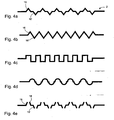
- the profilings could comprise pyramid-shaped or conical elements which are thus tapered outwards perpendicular to the plane of the flat gasket, as in FIG Fig. 4a and 4b shown.
- the tips of such a mold in addition to the effective thickening of the seal at this point cause a toothing of the profilings with the adjacent flanges.
- a larger bearing surface and thus higher friction is achieved, for example, by cylindrical or cuboidal elements, which in Fig. 4 c are again shown in cross section.
- the profiles could also be in the form of hemispherical profile elements (see Fig. 4d ), which distributes loads particularly evenly and effectively. In addition, any suitable shape is conceivable.
- the aim in all embodiments is to produce a surface which equals a thickening of the metallic base carrier.
- the geometry of the profilings is chosen so that in these areas an increase in the coefficients of friction up to a toothing effect between the seal and the flanges occurs and thereby the relative movements between the components are minimized.
- the functional structure serves as a kind of force and Wegbegrenzer for the seal.
- the functional structures may also be shaped such that portions of the functional structure plastically engage the flange surface penetrate and fix the components. This applies due to the different hardness of the materials in particular when, as usual, as the basic carrier material of the flat gasket, a steel sheet is used and the flanges are made of aluminum. Such a fixation can be achieved, for example, if, as described above, tapered profile elements are selected. Another possibility is to produce the profilings so that the carrier sheet is perforated, ie with open profile elements, as in Fig. 4e shown. In this exemplary embodiment, the profile elements 16 and 16 'are conical and open, so that in each case approximately circular edges 18 of the support plate arise, which can then engage with the flanges.
- the size of the functional structure can be adapted in every respect to the component conditions, for example to materials used, acting forces and special loads, etc.
- both the area of the embossed area and the size of the individual profile elements is variable.
- the elements can each be directly adjacent to each other, but they can also be at regular intervals to each other. These two possibilities are compared to one another for the case of the conical or cylindrical profile elements in FIG Fig. 4a and 4b compared. Of course, this also applies to the other possible embodiments, but was not listed there individually.
Abstract
Claims (13)
- Joint d'étanchéité plat soumis à de fortes sollicitations comprenant un support de base métallique (2) avec au moins une zone d'étanchéité (12), sachant que le support de base (2) est muni, dans au moins une zone prédéterminée hors des zones d'étanchéité (12), au moins partiellement d'une structure fonctionnelle (14), laquelle présente des profilages gravés (16, 16') du support de base (2) ; et sachant que le support de base (2) est muni d'un revêtement (4) en matériau élastomère ;
caractérisé en ce que l'épaisseur du revêtement (4) élastomère correspond à la hauteur des profilages (16, 16'), de façon à ce que le joint d'étanchéité plat présente partout la même épaisseur totale. - Joint d'étanchéité plat selon la revendication 1, dans lequel le support de base (2) comprend une ou plusieurs ouverture(s) de fixation (10) et dans lequel les structures fonctionnelles (14) avoisinent les ouvertures de fixation.
- Joint d'étanchéité plat selon la revendication 2, dans lequel les ouvertures de fixation (10) sont circulaires et dans lequel chaque ouverture de fixation (10) est entourée d'une structure fonctionnelle (14) avec un angle d'environ 180°.
- Joint d'étanchéité plat selon l'une des revendications précédentes, dans lequel les profilages gravés (16, 16') sont dirigés de manière symétrique et alternante sur les deux côtés du support de base métallique.
- Joint d'étanchéité plat selon l'une des revendications précédentes, dans lequel les profilages (16, 16') sont traversants et effectuent une perforation du support de base métallique (2).
- Joint d'étanchéité plat selon l'une des revendications précédentes, dans lequel les profilages (16, 16') sont répartis régulièrement sur la zone prédéfinie de la structure fonctionnelle (14).
- Joint d'étanchéité plat selon l'une des revendications précédentes, dans lequel les différents éléments de profilé (16, 16') sont hémisphériques.
- Joint d'étanchéité plat selon l'une des revendications précédentes, dans lequel les éléments de profilé (16, 16') sont cylindriques ou parallélépipédiques.
- Joint d'étanchéité plat selon l'une des revendications précédentes, dans lequel les éléments de profilé (16, 16') sont coniques.
- Joint d'étanchéité plat selon l'une des revendications précédentes, dans lequel les éléments de profilé (16, 16') sont pyramidaux.
- Joint d'étanchéité plat selon l'une des revendications précédentes, dans lequel le support de base métallique (2) est réalisé dans une tôle d'acier.
- Joint d'étanchéité plat selon l'une des revendications précédentes, dans lequel la tôle du support de base métallique (2) présente une épaisseur (a) entre 0,2 et 1 mm, l'épaisseur totale (x) du joint d'étanchéité plat est située entre 0,4 et 1 mm et l'épaisseur non revêtue mesurée (y) des structures fonctionnelles est de 0,4 à 1 mm.
- Joint d'étanchéité plat selon l'une des revendications précédentes, dans lequel les profilages de la structure fonctionnelle (14) sont produits par gravage.
Applications Claiming Priority (2)
| Application Number | Priority Date | Filing Date | Title |
|---|---|---|---|
| DE102006007311A DE102006007311A1 (de) | 2006-02-16 | 2006-02-16 | Flachdichtung für hohe Beanspruchung für Brennkraftmaschinen |
| PCT/EP2007/000436 WO2007093266A1 (fr) | 2006-02-16 | 2007-01-18 | Joint d'étanchéité plat soumis à de fortes sollicitations pour des moteurs à combustion interne |
Publications (2)
| Publication Number | Publication Date |
|---|---|
| EP1984659A1 EP1984659A1 (fr) | 2008-10-29 |
| EP1984659B1 true EP1984659B1 (fr) | 2011-04-27 |
Family
ID=37898542
Family Applications (1)
| Application Number | Title | Priority Date | Filing Date |
|---|---|---|---|
| EP07702869A Expired - Fee Related EP1984659B1 (fr) | 2006-02-16 | 2007-01-18 | Joint d'étanchéité plat soumis à de fortes sollicitations pour des moteurs à combustion interne |
Country Status (5)
| Country | Link |
|---|---|
| US (1) | US20100019459A1 (fr) |
| EP (1) | EP1984659B1 (fr) |
| DE (2) | DE102006007311A1 (fr) |
| ES (1) | ES2360890T3 (fr) |
| WO (1) | WO2007093266A1 (fr) |
Families Citing this family (9)
| Publication number | Priority date | Publication date | Assignee | Title |
|---|---|---|---|---|
| EP2288830B1 (fr) * | 2008-05-16 | 2011-12-14 | Ste Gesellschaft für Dichtungstechnik mbH | Garniture monocouche ou couche d' etancheite d' une garniture multicouche ainsi que procede pour sa fabrication |
| DE202008007444U1 (de) | 2008-06-04 | 2009-10-15 | Dolmar Gmbh | Verbrennungsmotor, insbesondere für handgeführte Arbeitsgeräte |
| JP6077210B2 (ja) * | 2011-12-22 | 2017-02-08 | トヨタ自動車株式会社 | 車両用後方監視装置 |
| US8752841B2 (en) | 2012-05-18 | 2014-06-17 | Federal-Mogul Corporation | Gasket with a compression limiter |
| DE102012105642A1 (de) * | 2012-06-27 | 2014-01-02 | Elringklinger Ag | Verfahren zum Herstellen eines Bauteils |
| JP2014113866A (ja) * | 2012-12-07 | 2014-06-26 | Nec Commun Syst Ltd | 状態監視システム、状態監視方法、状態検知装置、および状態検知プログラム |
| DE202013005717U1 (de) * | 2013-06-25 | 2014-09-26 | Alfred Jung | Tiefergeprägte Flachdichtung für große Flanschblattspalten von ca 5mm |
| DE202016104243U1 (de) * | 2016-08-02 | 2017-11-03 | Reinz-Dichtungs-Gmbh | Flachdichtung sowie Verbrennungsmotor mit einer derartigen Flachdichtung |
| CN107830170B (zh) * | 2017-12-22 | 2023-12-29 | 镇江贝斯特新材料股份有限公司 | 一种扬声器生产点胶头专用密封垫 |
Family Cites Families (27)
| Publication number | Priority date | Publication date | Assignee | Title |
|---|---|---|---|---|
| US2992151A (en) * | 1957-08-16 | 1961-07-11 | Victor Mfg & Gasket Co | Gasketing material |
| US3191950A (en) * | 1962-06-11 | 1965-06-29 | Electrada Corp | Reinforced gasket |
| US3794333A (en) * | 1972-07-20 | 1974-02-26 | Felt Products Mfg Co | Gasket |
| DE2455986C3 (de) * | 1974-11-27 | 1979-12-06 | Daimler-Benz Ag, 7000 Stuttgart | Dichtungsanordnung |
| AU2431077A (en) * | 1976-04-30 | 1978-10-19 | Dowty Seals Ltd | Seals and gaskets |
| JPS58106264A (ja) * | 1981-12-16 | 1983-06-24 | Nichias Corp | 耐熱シ−トガスケツト |
| US5478092A (en) * | 1992-07-31 | 1995-12-26 | Ishikawa Gasket Co., Ltd. | Metal laminate gasket with edge support beads |
| JPH0754692Y2 (ja) * | 1992-07-31 | 1995-12-18 | 石川ガスケット株式会社 | シリンダヘッド用金属積層形ガスケット |
| FR2724439B1 (fr) * | 1994-09-13 | 1996-10-25 | Curty Payen Sa | Joint metal-elastomere, notamment joint d'etancheite plat |
| US5938208A (en) * | 1994-12-30 | 1999-08-17 | Kokusan Parts Industry Co., Ltd. | Separate plate placed between adjacent valve bodies in a control valve unit of an automatic transmission |
| DE19523759A1 (de) * | 1995-06-29 | 1997-01-02 | Friedhelm Stecher | Flachdichtung und Verfahren zu ihrer Herstellung |
| JP3003026B2 (ja) * | 1996-10-07 | 2000-01-24 | 石川ガスケット株式会社 | 金属板ガスケット |
| FR2768211B1 (fr) * | 1997-09-09 | 1999-10-22 | Curty Payen Sa | Joint statique d'etancheite |
| FR2774430B1 (fr) * | 1998-02-05 | 2000-04-21 | Curty Payen Sa | Joint de culasse pour moteur a combustion interne |
| DE29804534U1 (de) * | 1998-03-13 | 1998-05-20 | Reinz Dichtungs Gmbh | Metallische Flachdichtung |
| DE19939869A1 (de) * | 1999-08-23 | 2001-04-12 | Elringklinger Gmbh | Flachdichtung |
| EP1298364B1 (fr) * | 2001-09-29 | 2005-06-22 | ElringKlinger AG | Joint de culasse métallique |
| JP2003130224A (ja) * | 2001-10-23 | 2003-05-08 | Ishikawa Gasket Co Ltd | メタルガスケット |
| CN100449181C (zh) * | 2002-04-04 | 2009-01-07 | 日本金属密封片株式会社 | 金属垫片 |
| US7147231B2 (en) * | 2003-03-05 | 2006-12-12 | Freudenberg-Nok General Partnership | Seal feature to prevent bending |
| FR2862892B1 (fr) * | 2003-11-27 | 2007-02-16 | Meillor Sa | Procede d'obtention d'une surepaisseur au niveau d'une tole et joint comprenant ladite tole |
| DE102005003017B4 (de) * | 2004-01-23 | 2019-10-24 | Koichi Hatamura | Metalldichtung |
| DE102004012905A1 (de) * | 2004-03-17 | 2005-10-13 | Elringklinger Ag | Zylinderkopfdichtung |
| DE102004026395A1 (de) * | 2004-05-29 | 2005-12-22 | Elringklinger Ag | Zylinderkopfdichtung |
| FR2873777B1 (fr) * | 2004-08-02 | 2008-10-03 | Fed Mogul Sealing Systems Soc | Joint statique d'etancheite |
| DE102004044851A1 (de) * | 2004-09-10 | 2006-03-16 | Elringklinger Ag | Zylinderkopfdichtung |
| DE202006003678U1 (de) * | 2006-03-09 | 2006-05-11 | Elringklinger Ag | Flachdichtung, insbesondere Zylinderkopfdichtung |
-
2006
- 2006-02-16 DE DE102006007311A patent/DE102006007311A1/de not_active Withdrawn
-
2007
- 2007-01-18 WO PCT/EP2007/000436 patent/WO2007093266A1/fr active Application Filing
- 2007-01-18 US US12/279,763 patent/US20100019459A1/en not_active Abandoned
- 2007-01-18 DE DE502007007052T patent/DE502007007052D1/de active Active
- 2007-01-18 ES ES07702869T patent/ES2360890T3/es active Active
- 2007-01-18 EP EP07702869A patent/EP1984659B1/fr not_active Expired - Fee Related
Also Published As
| Publication number | Publication date |
|---|---|
| ES2360890T3 (es) | 2011-06-10 |
| DE102006007311A1 (de) | 2007-08-30 |
| EP1984659A1 (fr) | 2008-10-29 |
| DE502007007052D1 (de) | 2011-06-09 |
| WO2007093266A1 (fr) | 2007-08-23 |
| US20100019459A1 (en) | 2010-01-28 |
Similar Documents
| Publication | Publication Date | Title |
|---|---|---|
| EP1984659B1 (fr) | Joint d'étanchéité plat soumis à de fortes sollicitations pour des moteurs à combustion interne | |
| DE112010003386B4 (de) | Metalldichtung | |
| EP1985898A1 (fr) | Joint plat métallique | |
| EP1298365B1 (fr) | Joint de culasse métallique | |
| EP0747614A1 (fr) | Joint de culasse métallique | |
| DE19634964A1 (de) | Metalldichtung | |
| EP2069659B1 (fr) | Joint plat avec limiteur de déformation | |
| DE102016002157A1 (de) | Metalldichtung | |
| DE202020104066U1 (de) | Dichtung und Gehäuse mit einer Dichtung | |
| DE3802741C2 (de) | Verfahren zur Verspannung von Schaufeln | |
| EP1482218A1 (fr) | Joint de culasse | |
| DE4421219C5 (de) | Metallische Flachdichtung mit örtlich einstellbarer Verformbarkeit | |
| DE102017215192B4 (de) | Flachdichtung, Zylinderkopfdichtung und Verfahren zur Herstellung solcher | |
| DE19847257A1 (de) | Werkzeug und Verfahren zum Herstellen eines Werkzeugs | |
| DE3440962C1 (de) | Verfahren zum Herstellen eines Kaefigs | |
| EP2041460B1 (fr) | Joint d'etancheite a cadre support de poids reduit | |
| DE102017119307A1 (de) | Zylinderkopfdichtung | |
| DE102006007313A1 (de) | Flachdichtung auf aufgeklebtem, bzw. eingesetztem Funktionselement für Brennkraftmaschine | |
| EP2841823B1 (fr) | Joint à cadre support à encombrement réduit | |
| EP1544519A1 (fr) | Méthode de réalisation d'une zone d'étanchéité d'un joint plat | |
| DE602004011452T2 (de) | Dichtung mit einem verdickten Blech | |
| DE102009032925B3 (de) | Verfahren zum Herstellen einer Dichtkontur auf einer flächig ausgebildeten Funktionslage | |
| EP1674770B1 (fr) | Joint métallique plat | |
| EP2841822B1 (fr) | Joint à cadre support à effet d'étanchéité amélioré | |
| DE10133598B4 (de) | Flachdichtung |
Legal Events
| Date | Code | Title | Description |
|---|---|---|---|
| PUAI | Public reference made under article 153(3) epc to a published international application that has entered the european phase |
Free format text: ORIGINAL CODE: 0009012 |
|
| 17P | Request for examination filed |
Effective date: 20080610 |
|
| AK | Designated contracting states |
Kind code of ref document: A1 Designated state(s): CZ DE ES FR GB IT |
|
| RBV | Designated contracting states (corrected) |
Designated state(s): CZ DE ES FR GB IT |
|
| 17Q | First examination report despatched |
Effective date: 20090309 |
|
| GRAP | Despatch of communication of intention to grant a patent |
Free format text: ORIGINAL CODE: EPIDOSNIGR1 |
|
| GRAS | Grant fee paid |
Free format text: ORIGINAL CODE: EPIDOSNIGR3 |
|
| GRAA | (expected) grant |
Free format text: ORIGINAL CODE: 0009210 |
|
| DAX | Request for extension of the european patent (deleted) | ||
| AK | Designated contracting states |
Kind code of ref document: B1 Designated state(s): CZ DE ES FR GB IT |
|
| REG | Reference to a national code |
Ref country code: GB Ref legal event code: FG4D Free format text: NOT ENGLISH |
|
| REF | Corresponds to: |
Ref document number: 502007007052 Country of ref document: DE Date of ref document: 20110609 Kind code of ref document: P |
|
| REG | Reference to a national code |
Ref country code: DE Ref legal event code: R096 Ref document number: 502007007052 Country of ref document: DE Effective date: 20110609 |
|
| REG | Reference to a national code |
Ref country code: ES Ref legal event code: FG2A Ref document number: 2360890 Country of ref document: ES Kind code of ref document: T3 Effective date: 20110610 |
|
| PLBE | No opposition filed within time limit |
Free format text: ORIGINAL CODE: 0009261 |
|
| STAA | Information on the status of an ep patent application or granted ep patent |
Free format text: STATUS: NO OPPOSITION FILED WITHIN TIME LIMIT |
|
| 26N | No opposition filed |
Effective date: 20120130 |
|
| REG | Reference to a national code |
Ref country code: DE Ref legal event code: R097 Ref document number: 502007007052 Country of ref document: DE Effective date: 20120130 |
|
| GBPC | Gb: european patent ceased through non-payment of renewal fee |
Effective date: 20120118 |
|
| PG25 | Lapsed in a contracting state [announced via postgrant information from national office to epo] |
Ref country code: GB Free format text: LAPSE BECAUSE OF NON-PAYMENT OF DUE FEES Effective date: 20120118 |
|
| PGFP | Annual fee paid to national office [announced via postgrant information from national office to epo] |
Ref country code: CZ Payment date: 20130103 Year of fee payment: 7 |
|
| REG | Reference to a national code |
Ref country code: ES Ref legal event code: FD2A Effective date: 20131022 |
|
| PG25 | Lapsed in a contracting state [announced via postgrant information from national office to epo] |
Ref country code: ES Free format text: LAPSE BECAUSE OF NON-PAYMENT OF DUE FEES Effective date: 20120119 |
|
| PG25 | Lapsed in a contracting state [announced via postgrant information from national office to epo] |
Ref country code: CZ Free format text: LAPSE BECAUSE OF NON-PAYMENT OF DUE FEES Effective date: 20140118 |
|
| REG | Reference to a national code |
Ref country code: FR Ref legal event code: PLFP Year of fee payment: 10 |
|
| REG | Reference to a national code |
Ref country code: FR Ref legal event code: PLFP Year of fee payment: 11 |
|
| REG | Reference to a national code |
Ref country code: FR Ref legal event code: PLFP Year of fee payment: 12 |
|
| PGFP | Annual fee paid to national office [announced via postgrant information from national office to epo] |
Ref country code: FR Payment date: 20181221 Year of fee payment: 13 |
|
| PGFP | Annual fee paid to national office [announced via postgrant information from national office to epo] |
Ref country code: DE Payment date: 20181219 Year of fee payment: 13 Ref country code: IT Payment date: 20190116 Year of fee payment: 13 |
|
| REG | Reference to a national code |
Ref country code: DE Ref legal event code: R119 Ref document number: 502007007052 Country of ref document: DE |
|
| PG25 | Lapsed in a contracting state [announced via postgrant information from national office to epo] |
Ref country code: DE Free format text: LAPSE BECAUSE OF NON-PAYMENT OF DUE FEES Effective date: 20200801 Ref country code: FR Free format text: LAPSE BECAUSE OF NON-PAYMENT OF DUE FEES Effective date: 20200131 |
|
| PG25 | Lapsed in a contracting state [announced via postgrant information from national office to epo] |
Ref country code: IT Free format text: LAPSE BECAUSE OF NON-PAYMENT OF DUE FEES Effective date: 20200118 |