EP1984659B1 - Flat seal for high loading for internal combustion engines - Google Patents
Flat seal for high loading for internal combustion engines Download PDFInfo
- Publication number
- EP1984659B1 EP1984659B1 EP07702869A EP07702869A EP1984659B1 EP 1984659 B1 EP1984659 B1 EP 1984659B1 EP 07702869 A EP07702869 A EP 07702869A EP 07702869 A EP07702869 A EP 07702869A EP 1984659 B1 EP1984659 B1 EP 1984659B1
- Authority
- EP
- European Patent Office
- Prior art keywords
- flat seal
- base support
- profilings
- seal according
- functional structure
- Prior art date
- Legal status (The legal status is an assumption and is not a legal conclusion. Google has not performed a legal analysis and makes no representation as to the accuracy of the status listed.)
- Expired - Fee Related
Links
Images


Classifications
-
- F—MECHANICAL ENGINEERING; LIGHTING; HEATING; WEAPONS; BLASTING
- F16—ENGINEERING ELEMENTS AND UNITS; GENERAL MEASURES FOR PRODUCING AND MAINTAINING EFFECTIVE FUNCTIONING OF MACHINES OR INSTALLATIONS; THERMAL INSULATION IN GENERAL
- F16J—PISTONS; CYLINDERS; SEALINGS
- F16J15/00—Sealings
- F16J15/02—Sealings between relatively-stationary surfaces
- F16J15/06—Sealings between relatively-stationary surfaces with solid packing compressed between sealing surfaces
- F16J15/10—Sealings between relatively-stationary surfaces with solid packing compressed between sealing surfaces with non-metallic packing
- F16J15/12—Sealings between relatively-stationary surfaces with solid packing compressed between sealing surfaces with non-metallic packing with metal reinforcement or covering
- F16J15/121—Sealings between relatively-stationary surfaces with solid packing compressed between sealing surfaces with non-metallic packing with metal reinforcement or covering with metal reinforcement
- F16J15/127—Sealings between relatively-stationary surfaces with solid packing compressed between sealing surfaces with non-metallic packing with metal reinforcement or covering with metal reinforcement the reinforcement being a compression stopper
-
- F—MECHANICAL ENGINEERING; LIGHTING; HEATING; WEAPONS; BLASTING
- F16—ENGINEERING ELEMENTS AND UNITS; GENERAL MEASURES FOR PRODUCING AND MAINTAINING EFFECTIVE FUNCTIONING OF MACHINES OR INSTALLATIONS; THERMAL INSULATION IN GENERAL
- F16J—PISTONS; CYLINDERS; SEALINGS
- F16J15/00—Sealings
- F16J15/02—Sealings between relatively-stationary surfaces
- F16J15/06—Sealings between relatively-stationary surfaces with solid packing compressed between sealing surfaces
- F16J15/08—Sealings between relatively-stationary surfaces with solid packing compressed between sealing surfaces with exclusively metal packing
- F16J15/0818—Flat gaskets
-
- F—MECHANICAL ENGINEERING; LIGHTING; HEATING; WEAPONS; BLASTING
- F16—ENGINEERING ELEMENTS AND UNITS; GENERAL MEASURES FOR PRODUCING AND MAINTAINING EFFECTIVE FUNCTIONING OF MACHINES OR INSTALLATIONS; THERMAL INSULATION IN GENERAL
- F16J—PISTONS; CYLINDERS; SEALINGS
- F16J15/00—Sealings
- F16J15/02—Sealings between relatively-stationary surfaces
- F16J15/06—Sealings between relatively-stationary surfaces with solid packing compressed between sealing surfaces
- F16J15/10—Sealings between relatively-stationary surfaces with solid packing compressed between sealing surfaces with non-metallic packing
- F16J15/12—Sealings between relatively-stationary surfaces with solid packing compressed between sealing surfaces with non-metallic packing with metal reinforcement or covering
- F16J15/121—Sealings between relatively-stationary surfaces with solid packing compressed between sealing surfaces with non-metallic packing with metal reinforcement or covering with metal reinforcement
- F16J15/122—Sealings between relatively-stationary surfaces with solid packing compressed between sealing surfaces with non-metallic packing with metal reinforcement or covering with metal reinforcement generally parallel to the surfaces
-
- F—MECHANICAL ENGINEERING; LIGHTING; HEATING; WEAPONS; BLASTING
- F16—ENGINEERING ELEMENTS AND UNITS; GENERAL MEASURES FOR PRODUCING AND MAINTAINING EFFECTIVE FUNCTIONING OF MACHINES OR INSTALLATIONS; THERMAL INSULATION IN GENERAL
- F16J—PISTONS; CYLINDERS; SEALINGS
- F16J15/00—Sealings
- F16J15/02—Sealings between relatively-stationary surfaces
- F16J15/06—Sealings between relatively-stationary surfaces with solid packing compressed between sealing surfaces
- F16J15/08—Sealings between relatively-stationary surfaces with solid packing compressed between sealing surfaces with exclusively metal packing
- F16J15/0818—Flat gaskets
- F16J2015/0856—Flat gaskets with a non-metallic coating or strip
-
- F—MECHANICAL ENGINEERING; LIGHTING; HEATING; WEAPONS; BLASTING
- F16—ENGINEERING ELEMENTS AND UNITS; GENERAL MEASURES FOR PRODUCING AND MAINTAINING EFFECTIVE FUNCTIONING OF MACHINES OR INSTALLATIONS; THERMAL INSULATION IN GENERAL
- F16J—PISTONS; CYLINDERS; SEALINGS
- F16J15/00—Sealings
- F16J15/02—Sealings between relatively-stationary surfaces
- F16J15/06—Sealings between relatively-stationary surfaces with solid packing compressed between sealing surfaces
- F16J15/08—Sealings between relatively-stationary surfaces with solid packing compressed between sealing surfaces with exclusively metal packing
- F16J15/0818—Flat gaskets
- F16J2015/0868—Aspects not related to the edges of the gasket
Definitions
- the invention relates to a flat gasket for high stress with increased wear resistance against damage by local overpressing and relative movements, especially for internal combustion engines.
- Flat gaskets are characterized in comparison to other types of gaskets, e.g. those with a metallic support frame, characterized in that the various functions of the sealing element, namely the sealing function and the transmission of the Verschraubungs kit are not separated.
- the sealing function of a flat gasket is achieved by pressing the gasket.
- the rigid metallic support frame assumes the function of power transmission and generates a defined sealing gap in which an elastic sealing material is pressed.
- Known basic types of flat gaskets are, for example, paper gaskets or gaskets made of an elastomer-coated metallic base carrier.
- the elastomer coating is stitched to increase the pressure.
- a possible embodiment is for example in the EP 1023549 described here, in which case the elastomeric material additionally comprises circumferential ridges forming sealing lips.
- EP 1 577 589 A1 discloses a generic flat gasket.
- a flat gasket according to claim 1, which has a metallic base support with at least one sealing area, wherein the base support is at least partially provided in at least one predetermined area outside the at least one sealing area with a functional structure having embossed profiles of the base support, and wherein the base support is provided with a coating of an elastomeric material, characterized in that the thickness of the elastomeric coating corresponds to the height of the profilings, so that the flat gasket has the same total thickness everywhere.
- the functional structure is provided with the elastomeric coating. Such a coating of the functional structure can additionally increase its rigidity.
- the thickness of the elastomeric coating of the functional structures corresponds to the height of the forms. In this way, edges and top surfaces of the structure continue to be exposed and provide increased friction with the flanges, while maintaining the increased rigidity of the structure as described above.
- the base support has one or more attachment openings, and the functional structures adjoin these attachment openings.
- the openings are usually used as screw holes, which is why in these areas, the pressing forces are highest through the screw.
- the attachment openings are circular, and each attachment opening is surrounded by a functional structure at an angle of about 180 °.
- embossed profiles of the functional structure are symmetrical on both sides of the metallic base support.
- the profiles are regularly distributed in the load area. This ensures a uniform as possible loading of the seal.
- the profilings are continuous and effect one Perforation of the metallic base carrier.
- the continuous perforations lead in each case to edges, which can further contribute to an increase in friction and toothing up to a plastic penetration into the flanges.
- the profile elements are hemispherical.
- a spherical surface is known to be particularly stable against deformation under stress.
- the profile elements are cylindrical or cuboid. This shape is very easy to produce with any embossing depth and offers a high degree of friction due to the surfaces on the flanges.
- the profile elements are conical or pyramidal.
- the tips of these profile elements can promote a strong toothing of the elements.
- the base support of the flat gasket is made of a steel sheet. This is a proven and common material for such carrier plates.
- the elastomeric coating may be a liquid elastomeric coating known as LEM (Liquid Elastomer Molding)
- the dimensions of a preferred embodiment of the invention are such that the base carrier sheet has a thickness between 0.2 and 1 mm, the total thickness of the flat gasket is between 0.4 and 1 mm, and the uncoated thickness of the functional structures is 0.4 to 1 mm is.
- profilings of the functional structure are produced by embossing the base carrier sheet.
- FIG. 1 shows an exemplary flat seal 1 according to the prior art.
- Fig. 1a is a perspective view while in Fig. 1b a cross-section is shown.
- the seal has a metallic base support 2 and is coated with an elastomeric material 4. From the elastomeric material also several, in this case three, parallel sealing lips 6 are formed. These have a triangular cross section and run as in Fig. 1a shown, each around the entire sealing opening around.
- the seal has attachment openings 10 for screwing with other components.
- the metallic core 2 has a thickness a of 0.2 mm
- the total thickness x of the gasket is 0.4 mm, so that in this example on each side Elastomer coating 4 of 0.1 mm thickness is applied.
- the thickness of the flat gasket, measured up to the tips of the sealing lips 6, is 0.8 mm.
- the included angle of the triangular sealing lips 6, which are each 1.5 mm apart (from tip to tip) should be about 100 °.
- the dimensions of the flat gasket may of course also deviate from these values.
- FIG. 2 shows by way of example a section of a flat gasket, which has a region which is provided with a functional structure according to the invention.
- the size of the structured region 14 is not fixed, but is chosen depending on the purpose of the seal and expected load distribution during manufacture.
- the functional structure is adjacent to a mounting opening 10 which serves to screw the flat gasket 1 between the flanges (not shown).
- the attachment opening 10 is only partially surrounded by the functional structure 14, preferably with an approximately semicircular area.
- On the opposite side of the mounting hole 10 are two sealing lips 6, which are not part of the invention, so that there is no functional structure is possible.
- the sealing region, which also includes the sealing lips, is referred to below as 12.
- the schematic enlargement of the functional structure shows the regularly alternating and bilaterally symmetrical arrangement of individual profile elements 16 and 16 ', wherein the elements impressed by one side are denoted by 16 and the elements of 16' impressed from the other side of the base support are otherwise identical are.
- the exact form of this functional structure will be described in more detail below.
- Fig. 3 are cross sections through various embodiments of flat gaskets shown.
- Fig. 3a is a cross-section through an embodiment of the prior art, so without embossed functional structure. The different areas otherwise correspond to those in Fig. 2 shown areas.
- the basic support 2 which consists of a metal sheet.
- This base support 2 is coated on both sides with an elastomer 4, in this example, both in the attachment region adjacent to the attachment opening 10, as well as in the sealing region 12.
- two sealing lips 6 can be seen on both surfaces of the seal, from the elastomeric coating 4 are formed.
- the elastomeric sealing lips 6 preferably have a triangular cross-section, but could also be in another form; In addition, the design, number and arrangement of the sealing lips 6 depends on the application and variable, as will be obvious to the expert. The sealing lips 6 are not part of the invention.
- FIG. 3b an uncoated non-inventive flat gasket shown.
- the base support 2 in the sealing area is identical to that in Fig. 3a shown seal, ie coated on both sides with an elastomer 4 and provided with sealing lips 6.
- the mounting area differs significantly.
- This region 14 has been provided with bilateral symmetrical profilings and, moreover, this region 14, which is referred to below as a functional structure, is not elastomer-coated.
- the profiles can be produced in various suitable shapes and are preferably hollow embossed from the carrier sheet from both sides. The elevations in the area of the functional structure act like a local thickening of the base support of the flat gasket without the need for additional material.
- the structure of the profiling also contributes, on the one hand, to the increase in friction, as will be explained below;
- the shape of the profiling can be used in many ways to influence the rigidity and the deformation properties of the seal. In this way, the load of the seal with respect to surface pressure and relative movement is reduced to uncritical values, which consequently leads to a significantly reduced wear of the seal and thus enables a longer service life.
- the carrier sheet thickness a may, as in the case of the prior art flat gasket, in one embodiment be between approximately 0.2 and 1 mm, the total thickness x together with the elastomeric coating being approximately 0.4 to 1.2 mm in total.
- the thickness y which extends from the lower end of the profiled elevations 16, 16 'to the upper end of the profilings, is approximately 0.3 to 1 mm.
- FIG Fig. 3c A similar embodiment not according to the invention is shown in FIG Fig. 3c
- the coating 4 can be so thick that the entire flat gasket, that is to say both in the sealing region 12 and in the region of the functional structure 14, can be seen.
- the elastomer may be as in Fig. 3d be applied only to such a height z, that the resulting by the profiling 16, 16 'recesses are filled according to the invention exactly.
- the remaining flat gasket is then according to the invention but not in 3d figure shown coated so that the flat gasket has the same total thickness everywhere.
- a filling or coating of the profilings with the elastomer causes an additional increase in the rigidity in this area and influences the deformation characteristic of the flat gasket.
- the coating thickness for example, dimensions as above for the description of Fig. 3b stated possible.
- the profiles or the functional structure in the critical regions can be designed and arranged in a variety of different forms.
- the profiles are executed on both sides, so by embossing in both directions of the metal support plate.
- the functional structure 14 or the profiling comprises a plurality of individual profile elements 16, 16 'of suitable shape, which are embossed over the desired area distributed from both sides. It is advantageous for a uniform force distribution and toothing effect that the profile elements 16, 16 'are shaped symmetrically and alternately from both sides, as it is made Figures 3 and 4 is apparent.
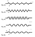
- the profilings could comprise pyramid-shaped or conical elements which are thus tapered outwards perpendicular to the plane of the flat gasket, as in FIG Fig. 4a and 4b shown.
- the tips of such a mold in addition to the effective thickening of the seal at this point cause a toothing of the profilings with the adjacent flanges.
- a larger bearing surface and thus higher friction is achieved, for example, by cylindrical or cuboidal elements, which in Fig. 4 c are again shown in cross section.
- the profiles could also be in the form of hemispherical profile elements (see Fig. 4d ), which distributes loads particularly evenly and effectively. In addition, any suitable shape is conceivable.
- the aim in all embodiments is to produce a surface which equals a thickening of the metallic base carrier.
- the geometry of the profilings is chosen so that in these areas an increase in the coefficients of friction up to a toothing effect between the seal and the flanges occurs and thereby the relative movements between the components are minimized.
- the functional structure serves as a kind of force and Wegbegrenzer for the seal.
- the functional structures may also be shaped such that portions of the functional structure plastically engage the flange surface penetrate and fix the components. This applies due to the different hardness of the materials in particular when, as usual, as the basic carrier material of the flat gasket, a steel sheet is used and the flanges are made of aluminum. Such a fixation can be achieved, for example, if, as described above, tapered profile elements are selected. Another possibility is to produce the profilings so that the carrier sheet is perforated, ie with open profile elements, as in Fig. 4e shown. In this exemplary embodiment, the profile elements 16 and 16 'are conical and open, so that in each case approximately circular edges 18 of the support plate arise, which can then engage with the flanges.
- the size of the functional structure can be adapted in every respect to the component conditions, for example to materials used, acting forces and special loads, etc.
- both the area of the embossed area and the size of the individual profile elements is variable.
- the elements can each be directly adjacent to each other, but they can also be at regular intervals to each other. These two possibilities are compared to one another for the case of the conical or cylindrical profile elements in FIG Fig. 4a and 4b compared. Of course, this also applies to the other possible embodiments, but was not listed there individually.
Abstract
Description
Die Erfindung betrifft eine Flachdichtung für hohe Beanspruchung mit erhöhter Verschleißfestigkeit gegen Schäden durch lokale Überpressung und Relativbewegungen, insbesondere für Brennkraftmaschinen.The invention relates to a flat gasket for high stress with increased wear resistance against damage by local overpressing and relative movements, especially for internal combustion engines.
Flachdichtungen zeichnen sich im Vergleich zu anderen Dichtungstypen, z.B. solchen mit einem metallischen Trägerrahmen, dadurch aus, dass die verschiedenen Funktionen des Dichtelements, nämlich die Dichtfunktion sowie die Übertragung der Verschraubungskräfte, nicht voneinander getrennt sind. Die Dichtfunktion einer Flachdichtung wird durch Verpressung der Dichtung erreicht. Bei einer Funktionstrennung übernimmt dagegen der steife metallische Trägerrahmen die Funktion der Kraftübertragung und erzeugt einen definierten Dichtspalt, in dem ein elastischer Dichtungswerkstoff verpresst wird.Flat gaskets are characterized in comparison to other types of gaskets, e.g. those with a metallic support frame, characterized in that the various functions of the sealing element, namely the sealing function and the transmission of the Verschraubungskräfte are not separated. The sealing function of a flat gasket is achieved by pressing the gasket. In a separation of functions, however, the rigid metallic support frame assumes the function of power transmission and generates a defined sealing gap in which an elastic sealing material is pressed.
Bekannte Grundarten von Flachdichtungen sind zum Beispiel Papierdichtungen oder Dichtungen aus einem elastomerbeschichteten metallischen Grundträger. Dabei ist normalerweise die Elastomerbeschichtung zur Pressungserhöhung gesickt. Eine mögliche Ausführungsform ist beispielsweise in der
Solche Dichtungen werden in Bereichen eingesetzt, in denen keine besonders großen Bauteiltoleranzen ausgeglichen werden müssen. Alle diese Flachdichtungen haben gemeinsam, dass sie im Kraftfluss der Gehäuse- oder Flanschverschraubungen liegen und somit durch die Verschraubungskräfte stark belastet werden. Durch unterschiedliche Gehäuseformen und Verschraubungsanordnungen ergeben sich unterschiedliche Tragbilder im Dichtungsverlauf.Such seals are used in areas where no particularly large component tolerances must be compensated. All these gaskets have in common that they lie in the power flow of the housing or Flanschverschraubungen and thus are heavily loaded by the Verschraubungskräfte. Different housing shapes and bolting arrangements result in different contact patterns in the course of the seal.
Durch Relativbewegungen und hohe Flächenpressungen zwischen den Flanschen, zwischen denen die Dichtungen eingepresst sind, können Flachdichtungen jedoch mehr oder minder stark beschädigt werden. Solche Relativbewegungen treten zum Beispiel auf, wenn Flachdichtungen in beweglichen Anordnungen eingesetzt werden, wie in einem Motor, und können nicht verhindert werden. Auch der hohe Anpressdruck kann bauformbedingt nicht wesentlich verringert werden, da ansonsten die Dichtwirkung der Flachdichtung verringert wird. Umgekehrt könnte eine weitere Erhöhung des Anpressdrucks bzw. der Verschraubungskräfte zwar die Relativbewegungen verringern, würde jedoch auch eine erhöhte Belastung der Dichtung verursachen. Die Beschädigungen und mechanischen Verschleißerscheinungen können letztendlich zu einem Versagen der Dichtfunktion führen.By relative movements and high surface pressures between the flanges, between which the seals are pressed, but flat gaskets can be damaged more or less. Such relative movements occur, for example, when flat gaskets are used in movable assemblies, such as in a motor, and can not be prevented. The high contact pressure can not be significantly reduced due to the design, otherwise the sealing effect of the flat gasket is reduced. Conversely, a further increase in the contact pressure or the screwing forces could indeed reduce the relative movements, but would also cause an increased load on the seal. The damage and mechanical signs of wear can ultimately lead to a failure of the sealing function.
Die kritischen Bereiche, in denen diese Verschleißerscheinungen hauptsächlich auftreten, liegen im allgemeinen im Bereich der Verschraubungen. Auch eine geringe Flanschfläche oder Kontaktfläche der Dichtung kann in lokalen Bereichen zu einer starken Beanspruchung führen.The critical areas in which these wear phenomena mainly occur, are generally in the field of glands. Even a small flange surface or contact surface of the seal can lead to heavy stress in local areas.
Diese Art von bekannten Flachdichtungen kann daher bei lokal sehr hohen Pressungen und/oder Verformungen von Gehäusebauteilen sowie bei Relativbewegungen oft nicht eingesetzt werden. Dies gilt speziell bei höher beanspruchten Gehäusen mit hohen Verschraubungskräften und kleinen Flansch- oder Kontaktflächen. In solchen Fällen muss also oftmals eine andere, meist teurere Dichtungsbauart gewählt werden, zum Beispiel eine Dichtung mit metallischem Trägerrahmen, an der die Dichtlippen stirnseitig anvulkanisiert sind. Bei einer solchen Dichtung ist wieder eine Funktionstrennung vorhanden, da die Übertragung der Überschraubungskräfte und die Dichtfunktion von verschiedenen Teilen der Dichtung gewährleistet werden.This type of known flat gaskets can therefore often not be used for locally very high pressures and / or deformations of housing components as well as relative movements. This is especially true in higher-loaded housings with high bolting forces and small flange or contact surfaces. In such cases, therefore, often a different, usually more expensive seal type must be selected, for example, a seal with metallic support frame, on which the sealing lips are vulcanized on the front side. In such a seal, a functional separation is again present, since the transmission of the union forces and the sealing function of different parts of the seal are ensured.
Daher ist es Aufgabe der Erfindung, eine Flachdichtung bereitzustellen, bei der ohne Hinzufügen von zusätzlichen Bauteilen eine Entlastung dieser kritischen Bereiche erreicht wird, so dass Beschädigungen aufgrund der angesprochenen Relativbewegungen und Überpressungen verringert oder vollständig vermieden werden und so die Lebensdauer der Dichtung deutlich erhöht wird.It is therefore an object of the invention to provide a gasket in which, without the addition of additional components, a relief of these critical areas is achieved, so that damage due to the above relative movements and Overpressures are reduced or completely avoided and so the life of the seal is significantly increased.
Die Aufgabe wird gelöst durch eine Flachdichtung nach Anspruch 1, die einen metallischen Grundträger mit mindestens einem Dichtbereich aufweist, wobei der Grundträger in mindestens einem vorbestimmten Bereich außerhalb des mindestens einen Dichtbereichs zumindest teilweise mit einer funktionalen Struktur versehen ist, welche eingeprägte Profilierungen des Grundträgers aufweist, und wobei der Grundträger mit einer Beschichtung aus einem elastomeren Material versehen ist, dadurch gekennzeichnet, dass die Dicke der elastomeren Beschichtung der Höhe der Profilierungen entspricht, so dass die Flachdichtung überall die gleiche Gesamtdicke aufweist.The object is achieved by a flat gasket according to claim 1, which has a metallic base support with at least one sealing area, wherein the base support is at least partially provided in at least one predetermined area outside the at least one sealing area with a functional structure having embossed profiles of the base support, and wherein the base support is provided with a coating of an elastomeric material, characterized in that the thickness of the elastomeric coating corresponds to the height of the profilings, so that the flat gasket has the same total thickness everywhere.
Durch eine derartige aus der eigentlichen Dichtung herausgearbeitete Strukturierung wird eine Art lokale Funktionstrennung einer einstückigen Dichtung bewirkt, da nun die Kraftübertragung verstärkt oder hauptsächlich in den effektiv verdickten Bereichen der Dichtung stattfindet. Die Bereiche der Flachdichtung, welche die Dichtfunktion gewährleisten, werden damit deutlich weniger belastet. Zusätzlich wird durch die Struktur und Form der Profilierung die Reibung zwischen Dichtung und Flanschen erhöht oder sogar eine Verzahnung der Elemente bewirkt, so dass die Relativbewegungen verringert werden.Such structuring, worked out of the actual gasket, effects a kind of local functional separation of a one-piece gasket, since now the power transmission is increased or takes place mainly in the effectively thickened regions of the gasket. The areas of the flat gasket, which ensure the sealing function, are therefore significantly less stressed. In addition, the structure and shape of the profiling increases the friction between the seal and the flanges or even causes a toothing of the elements, so that the relative movements are reduced.
Die funktionale Struktur ist mit der elastomeren Beschichtung versehen. Eine solche Beschichtung der funktionalen Struktur kann deren Steifigkeit zusätzlich erhöhen.The functional structure is provided with the elastomeric coating. Such a coating of the functional structure can additionally increase its rigidity.
Erfindungsgemäß entspricht die Dicke der elastomeren Beschichtung der funktionalen Strukturen der Höhe der Ausprägungen. Auf diese Weise liegen Kanten und obere Flächen der Struktur weiterhin frei und sorgen für eine erhöhte Reibung mit den Flanschen, während die erhöhte Steifigkeit der Struktur wie vorstehend beschrieben erhalten bleibt.According to the invention, the thickness of the elastomeric coating of the functional structures corresponds to the height of the forms. In this way, edges and top surfaces of the structure continue to be exposed and provide increased friction with the flanges, while maintaining the increased rigidity of the structure as described above.
In einer bevorzugten Ausführungsform weist der Grundträger eine oder mehrere Befestigungsöffnungen auf, und die funktionalen Strukturen grenzen an diesen Befestigungsöffnungen an. Die Öffnungen dienen üblicherweise als Verschraubungslöcher, weshalb in diesen Bereichen die Presskräfte durch die Verschraubung am höchsten sind.In a preferred embodiment, the base support has one or more attachment openings, and the functional structures adjoin these attachment openings. The openings are usually used as screw holes, which is why in these areas, the pressing forces are highest through the screw.
Bevorzugt sind die Befestigungsöffnungen kreisförmig, und jede Befestigungsöffnung ist mit einem Winkel von etwa 180° von einer funktionalen Struktur umgeben.Preferably, the attachment openings are circular, and each attachment opening is surrounded by a functional structure at an angle of about 180 °.
Es ist außerdem bevorzugt, dass die eingeprägten Profilierungen der funktionalen Struktur symmetrisch auf beiden Seiten des metallischen Grundträgers ausgeführt sind.It is also preferred that the embossed profiles of the functional structure are symmetrical on both sides of the metallic base support.
Bevorzugt sind die Profilierungen regelmäßig in dem Belastungsbereich verteilt. Damit wird eine möglichst gleichmäßige Belastung der Dichtung gewährleistet.Preferably, the profiles are regularly distributed in the load area. This ensures a uniform as possible loading of the seal.
In einer Ausführungsform sind die Profilierungen durchgängig und bewirken eine Perforierung des metallischen Grundträgers. Die durchgängigen Perforierungen führen jeweils zu Kanten, die weiter zu einer Reibungserhöhung und Verzahnung bis hin zu einem plastischen Eindringen in die Flansche beitragen können.In one embodiment, the profilings are continuous and effect one Perforation of the metallic base carrier. The continuous perforations lead in each case to edges, which can further contribute to an increase in friction and toothing up to a plastic penetration into the flanges.
In einer bevorzugten Ausführungsform sind die Profilelemente halbkugelförmig. Eine kugelförmige Oberfläche ist bekanntermaßen besonders stabil gegen Verformungen unter Belastung.In a preferred embodiment, the profile elements are hemispherical. A spherical surface is known to be particularly stable against deformation under stress.
In einer weiteren bevorzugten Ausführungsform sind die Profilelemente zylinderförmig oder quaderförmig. Diese Form ist sehr einfach mit beliebiger Prägetiefe herzustellen und bietet eine hohe Reibung durch die an den Flanschen anliegenden Flächen.In a further preferred embodiment, the profile elements are cylindrical or cuboid. This shape is very easy to produce with any embossing depth and offers a high degree of friction due to the surfaces on the flanges.
Nach einer weiteren bevorzugten Ausführungsform sind die Profilelemente kegelförmig oder pyramidenförmig. Die Spitzen dieser Profilelemente können eine starke Verzahnung der Elemente begünstigen.According to a further preferred embodiment, the profile elements are conical or pyramidal. The tips of these profile elements can promote a strong toothing of the elements.
Bevorzugt ist der Grundträger der Flachdichtung aus einem Stahlblech gefertigt ist. Dies ist ein bewährtes und übliches Material für solche Trägerbleche.Preferably, the base support of the flat gasket is made of a steel sheet. This is a proven and common material for such carrier plates.
Die elastomere Beschichtung kann eine Flüssig-Elastomer-Beschichtung sein, die als LEM (Liquid Elastomer Moulding) bekannt istThe elastomeric coating may be a liquid elastomeric coating known as LEM (Liquid Elastomer Molding)
Die Abmessungen einer bevorzugten Ausführungsform der Erfindung sind so, dass das Grundträgerblech eine Dicke zwischen 0,2 und 1 mm aufweist, die Gesamtdicke der Flachdichtung zwischen 0,4 und 1 mm liegt und die unbeschichtet gemessene Dicke der funktionalen Strukturen 0,4 bis 1 mm beträgt.The dimensions of a preferred embodiment of the invention are such that the base carrier sheet has a thickness between 0.2 and 1 mm, the total thickness of the flat gasket is between 0.4 and 1 mm, and the uncoated thickness of the functional structures is 0.4 to 1 mm is.
Es ist bevorzugt, dass die Profilierungen der funktionalen Struktur durch Prägen des Grundträgerblechs erzeugt werden.It is preferred that the profilings of the functional structure are produced by embossing the base carrier sheet.
Im folgenden wird die Erfindung mit Hilfe beispielhafter Ausführungsformen und Zeichnungen ausführlich beschrieben.
-
Figuren 1a und 1b zeigen die Struktur einer Flachdichtung mit elastomerer Beschichtung nach dem Stand der Technik. -
Figur 2 -
Figur 3a zeigt einen Querschnitt durch eine Flachdichtung nach dem Stand der Technik. -
Figur 3b zeigt im Querschnitt nicht eine erfindungsgemäße Ausführungsform einer Flachdichtung mit einer unbeschichteten funktionalen Struktur. -
Figur 3c zeigt im Querschnitt eine nicht erfindungsgemäße Ausführungsform mit einer elastomerbeschichteten funktionalen Struktur. -
Figur 3d zeigt im Querschnitt eine nicht erfindungsgemäße Ausführungsform mit einer elastomerbeschichteten funktionalen Struktur, wobei die Beschichtung erfindungsgemäß nur bis zur Höhe der Profilierungen aufgebracht ist. -
Figur 4a zeigt einen schematischen Querschnitt einer Ausführungsform der funktionalen Struktur der Erfindung mit geschlossenen pyramidenförmigen oder kegelförmigen Profilelementen. -
Figur 4b zeigt eine weitere Ausführungsform der funktionalen Struktur mit pyramidenförmigen/kegelförmigen Elementen, wobei die Elemente direkt aneinander angrenzen. -
Figur 4c zeigt eine weitere Ausführungsform der funktionalen Struktur mit geschlossenen zylindrischen oder quaderförmigen Elemente. -
Figur 4d zeigt eine weitere Ausführungsform der funktionalen Struktur mit geschlossenen halbkugelförmigen Elementen. -
Figur 4e zeigt eine Ausführungsform der funktionalen Struktur der Erfindung mit offenen kegelförmigen Elementen.
-
FIGS. 1a and 1b show the structure of a flat gasket with elastomeric coating according to the prior art. -
FIG. 2 shows an embodiment of a flat gasket with a Area that has a functional structure. -
FIG. 3a shows a cross section through a flat gasket according to the prior art. -
FIG. 3b does not show in cross section an embodiment according to the invention of a flat gasket with an uncoated functional structure. -
Figure 3c shows in cross section a non-inventive embodiment with an elastomer-coated functional structure. -
3d figure shows in cross section a non-inventive embodiment with an elastomer-coated functional structure, the coating according to the invention is applied only up to the height of the profilings. -
FIG. 4a shows a schematic cross section of an embodiment of the functional structure of the invention with closed pyramidal or conical profile elements. -
FIG. 4b shows a further embodiment of the functional structure with pyramidal / conical elements, wherein the elements directly adjacent to each other. -
Figure 4c shows a further embodiment of the functional structure with closed cylindrical or cuboidal elements. -
FIG. 4d shows a further embodiment of the functional structure with closed hemispherical elements. -
Figure 4e shows an embodiment of the functional structure of the invention with open conical elements.
Weitere Einzelheiten der Dichtung wie zusätzliche Dichtelemente, Sicken etc. sind hier nicht gezeigt, sind dem Fachmann aber bekannt. Wie in
Da die kritischen Belastungen im Allgemeinen zwar aufgrund der Kraftübertragung durch die Verschraubung im Bereich der Befestigungsöffnungen bzw. Verschraubungslöcher 10 auftreten, jedoch nicht ausschließlich dort, können derartige funktionale Strukturen 14 alternativ oder zusätzlich auch an anderen geeigneten Stellen auf einer Flachdichtung angebracht werden, wobei der Bereich der funktionalen Strukturen 14 außerhalb der Dichtbereiche 12 liegen muss, um die Dichtfunktion weiter zu gewährleisten. Die günstigste Lage dieser Stellen, die sich aus der Belastungsverteilung der Dichtung ergibt, kann mittels einem beliebigen geeigneten Verfahren ermittelt werden. Starke Belastungen und Verschleißerscheinungen treten unter anderem auch bei sehr kleinen Flanschflächen und Kontaktflächen der Dichtung auf.Although the critical loads generally occur due to the transmission of force through the screw connection in the region of the fastening openings or screw
In
Als Vergleich zu dieser beschichteten Flachdichtung nach dem Stand der Technik ist in
Die Trägerblechdicke a kann wie bereits bei der Flachdichtung nach dem Stand der Technik in einer Ausführungsform zwischen etwa 0,2 bis 1 mm liegen, wobei die Gesamtdicke x zusammen mit der elastomeren Beschichtung bei insgesamt etwa 0,4 bis 1,2 mm liegt. Im Bereich der funktionalen Struktur liegt die Dicke y, die sich vom unteren Ende der Profilerhebungen 16, 16' bis zum oberen Ende der Profilierungen erstreckt, bei etwa 0,3 bis 1 mm.The carrier sheet thickness a may, as in the case of the prior art flat gasket, in one embodiment be between approximately 0.2 and 1 mm, the total thickness x together with the elastomeric coating being approximately 0.4 to 1.2 mm in total. In the area of the functional structure, the thickness y, which extends from the lower end of the profiled
Ein ähnliches nicht erfindungsgemäßes Ausführungsbeispiel ist in
Die Profilierungen bzw. die funktionale Struktur in den kritischen Bereichen können in einer Vielzahl verschiedener Formen ausgeführt und angeordnet sein. Bevorzugt sind die Profilierungen beidseitig ausgeführt, also durch Prägung in beide Richtungen des Metallträgerblechs. Dabei umfasst die funktionale Struktur 14 bzw. die Profilierung eine Vielzahl von einzelnen Profilelementen 16, 16' geeigneter Form, die über den gewünschten Bereich verteilt von beiden Seiten eingeprägt sind. Dabei ist für eine gleichmäßige Kraftverteilung und Verzahnungswirkung vorteilhaft, dass die Profilelemente 16, 16' symmetrisch und abwechselnd von beiden Seiten geprägt werden, wie es aus
So könnten die Profilierungen pyramidenförmige oder kegelförmige Elemente umfassen, die also senkrecht zur Ebene der Flachdichtung nach außen hin spitz zulaufen, wie in
In verschiedenen Ausführungsformen können die funktionalen Strukturen außerdem so geformt sein, dass Teile der funktionalen Struktur plastisch in die Flanschoberfläche eindringen und die Bauteile fixieren. Dies gilt aufgrund der unterschiedlichen Härte der Materialien insbesondere dann, wenn wie üblich als Grundträgermaterial der Flachdichtung ein Stahlblech verwendet wird und die Flansche aus Aluminium gefertigt sind. Eine solche Fixierung kann zum Beispiel erreicht werden, wenn wie oben beschrieben spitz zulaufende Profilelemente gewählt werden. Eine weitere Möglichkeit ist, die Profilierungen so zu erzeugen, dass das Trägerblech perforiert wird, d.h. mit offenen Profilelementen, wie in
Die Größe der funktionalen Struktur kann in jeder Hinsicht an die Bauteilgegebenheiten angepasst werden, zum Beispiel an verwendete Materialien, wirkende Kräfte und besondere Belastungen, etc. Dabei ist selbstverständlich sowohl die Fläche des geprägten Bereichs als auch die Größe der einzelnen Profilelemente variabel. Die Elemente können jeweils direkt aneinander angrenzen, sie können sich aber auch in gleichmäßigen Abständen zueinander befinden. Diese beiden Möglichkeiten sind einander als Vergleich für den Fall der kegel- oder zylinderförmigen Profilelemente in
Da diese Art von Flachdichtung mit Metallträger typischerweise vom Coil gefertigt wird und verschiedene Prozessschritte bis hin zum Ausstanzen der Dichtung durchläuft, kann die Erzeugung der funktionalen Struktur ohne besonderen Aufwand sehr einfach in den Stanzprozess integriert werden. Dabei ist auch denkbar, dass zur Vereinfachung verschiedene standardisierte Prägestempel mit häufig wiederkehrenden Elementen, wie z.B. Schraubenprofile M6 oder M8, eingesetzt werden. Die herausgeprägte funktionale Struktur kann durch ihre Geometrie und die dadurch hervorgerufene Umformung sowie durch Kaltverfestigungsvorgänge in ihrer Steifigkeit gezielt beeinflusst werden, um für die jeweilige Anwendung ideale Ergebnisse zu erhalten.Since this type of flat gasket with metal support is typically manufactured by the coil and goes through various process steps up to the punching of the seal, the generation of the functional structure can be very easily integrated into the stamping process without any special effort. It is also conceivable that for simplification, various standardized dies with frequently recurring elements, such as screw profiles M6 or M8, are used. The pronounced functional structure can be specifically influenced by its geometry and the resulting deformation as well as by work hardening in its rigidity in order for the respective application to get ideal results.
Somit sind zur erfindungsgemäßen Anpassung der Flachdichtung auch an hohe Verpressungskräfte und starke Relativbewegungen keine weiteren Elemente nötig, und eine einfache Integration in bestehende Fertigungsprozesse ist möglich.Thus, no further elements are required for high compression forces and strong relative movements for the adaptation of the flat gasket according to the invention, and a simple integration into existing manufacturing processes is possible.
Vorstehend wurden verschiedene Ausführungsformen der Erfindung dargestellt und beschrieben. Dabei ist es jedoch für den Fachmann offensichtlich, dass diese nur als Beispiele genannt wurden und den Schutzbereich der Erfindung nicht einschränken sollen. Veränderungen im Rahmen der beigefügten Schutzansprüche sind auf verschiedene Weise möglich.In the foregoing, various embodiments of the invention have been illustrated and described. However, it is obvious to those skilled in the art that these have been mentioned only as examples and are not intended to limit the scope of the invention. Changes within the scope of the attached claims are possible in various ways.
Claims (13)
- Flat seal for high stress, comprising a metallic base support (2) with at least one sealing region (12),
in which the base support (2) is provided in at least one pre-determined region outside the sealing regions (12) at least partially with a functional structure (14), which has impressed profilings (16, 16') of the base support (2);
in which the base support (2) is provided with a coating (4) of an elastomer material; characterized in that the thickness of the elastomer coating (4) corresponds to the height of the profilings (16, 16') so that the flat seal has the same total thickness all over. - Flat seal according to claim 1, in which the base support (2) comprises one or more fastening openings (10), and in which the functional structures (14) are adjacent to the fastening openings.
- Flat seal according to claim 2, in which the fastening openings (10) are circular, and in which each fastening opening (10) is surrounded at an angle of approximately 180° by a functional structure (14).
- Flat seal according to any of the preceding claims, in which the impressed profilings (16, 16') are formed symmetrically and alternately on both sides of the metallic base support.
- Flat seal according to any of the preceding claims, in which the profilings (16, 16') are continous and bring about a perforating of the metallic base support (2).
- Flat seal according to any of the preceding claims, in which the profilings (16, 16') are distributed uniformly over the predetermined region of the functional structure (14).
- Flat seal according to any of the preceding claims, in which the individual profile elements (16, 16') are hemispherical.
- Flat seal according to any of the preceding claims, in which the profile elements (16, 16') are cylindrical or parallelepiped in shape.
- Flat seal according to any of the preceding claims, in which the profile elements (16, 16') are tapered.
- Flat seal according to any of the preceding claims, in which the profile elements (16, 16') are pyramidal.
- Flat seal according to any of the preceding claims, in which the base support (2) is made from a steel plate.
- Flat seal according to any of the preceding claims, in which the base support plate (2) has a thickness (a) between 0.2 and 1 mm, the total thickness (x) of the flat seal is between 0.4 and 1 mm and the uncoated measured thickness (y) of the functional structures is 0.4 to 1 mm.
- Flat seal according to any of the preceding claims, in which the profilings of the functional structure (14) are produced by impressing.
Applications Claiming Priority (2)
| Application Number | Priority Date | Filing Date | Title |
|---|---|---|---|
| DE102006007311A DE102006007311A1 (en) | 2006-02-16 | 2006-02-16 | Flat gasket for heavy use for internal combustion engines |
| PCT/EP2007/000436 WO2007093266A1 (en) | 2006-02-16 | 2007-01-18 | Flat seal for high loading for internal combustion engines |
Publications (2)
| Publication Number | Publication Date |
|---|---|
| EP1984659A1 EP1984659A1 (en) | 2008-10-29 |
| EP1984659B1 true EP1984659B1 (en) | 2011-04-27 |
Family
ID=37898542
Family Applications (1)
| Application Number | Title | Priority Date | Filing Date |
|---|---|---|---|
| EP07702869A Expired - Fee Related EP1984659B1 (en) | 2006-02-16 | 2007-01-18 | Flat seal for high loading for internal combustion engines |
Country Status (5)
| Country | Link |
|---|---|
| US (1) | US20100019459A1 (en) |
| EP (1) | EP1984659B1 (en) |
| DE (2) | DE102006007311A1 (en) |
| ES (1) | ES2360890T3 (en) |
| WO (1) | WO2007093266A1 (en) |
Families Citing this family (9)
| Publication number | Priority date | Publication date | Assignee | Title |
|---|---|---|---|---|
| ATE537388T1 (en) * | 2008-05-16 | 2011-12-15 | Dichtungstechnik Mbh Soc Ges | SINGLE-LAYER SEAL OR SEALING LAYER OF A MULTI-LAYER SEAL AND METHOD FOR THE PRODUCTION THEREOF |
| DE202008007444U1 (en) | 2008-06-04 | 2009-10-15 | Dolmar Gmbh | Internal combustion engine, in particular for hand-held implements |
| JP6077210B2 (en) * | 2011-12-22 | 2017-02-08 | トヨタ自動車株式会社 | Vehicle rearward monitoring device |
| US8752841B2 (en) | 2012-05-18 | 2014-06-17 | Federal-Mogul Corporation | Gasket with a compression limiter |
| DE102012105642A1 (en) * | 2012-06-27 | 2014-01-02 | Elringklinger Ag | Method for manufacturing component for fuel cell, involves providing seam in carrier layer before application of coating, where sealing line is deformable in height, and forms height-adapting contact surface for forcing away edge |
| JP2014113866A (en) * | 2012-12-07 | 2014-06-26 | Nec Commun Syst Ltd | State monitoring system, state monitoring method, state sensing device, and state sensing program |
| DE202013005717U1 (en) * | 2013-06-25 | 2014-09-26 | Alfred Jung | Deep stamped flat gasket for large flange blade gaps of approx. 5mm |
| DE202016104243U1 (en) * | 2016-08-02 | 2017-11-03 | Reinz-Dichtungs-Gmbh | Flat gasket and internal combustion engine with such a flat gasket |
| CN107830170B (en) * | 2017-12-22 | 2023-12-29 | 镇江贝斯特新材料股份有限公司 | Loudspeaker production point sealing pad special for rubber head |
Family Cites Families (27)
| Publication number | Priority date | Publication date | Assignee | Title |
|---|---|---|---|---|
| US2992151A (en) * | 1957-08-16 | 1961-07-11 | Victor Mfg & Gasket Co | Gasketing material |
| US3191950A (en) * | 1962-06-11 | 1965-06-29 | Electrada Corp | Reinforced gasket |
| US3794333A (en) * | 1972-07-20 | 1974-02-26 | Felt Products Mfg Co | Gasket |
| DE2455986C3 (en) * | 1974-11-27 | 1979-12-06 | Daimler-Benz Ag, 7000 Stuttgart | Sealing arrangement |
| AU2431077A (en) * | 1976-04-30 | 1978-10-19 | Dowty Seals Ltd | Seals and gaskets |
| JPS58106264A (en) * | 1981-12-16 | 1983-06-24 | Nichias Corp | Heat-resisting sheet gasket |
| JPH0754692Y2 (en) * | 1992-07-31 | 1995-12-18 | 石川ガスケット株式会社 | Metallic laminated gasket for cylinder head |
| US5478092A (en) * | 1992-07-31 | 1995-12-26 | Ishikawa Gasket Co., Ltd. | Metal laminate gasket with edge support beads |
| FR2724439B1 (en) * | 1994-09-13 | 1996-10-25 | Curty Payen Sa | METAL-ELASTOMER GASKET, ESPECIALLY FLAT GASKET |
| US5938208A (en) * | 1994-12-30 | 1999-08-17 | Kokusan Parts Industry Co., Ltd. | Separate plate placed between adjacent valve bodies in a control valve unit of an automatic transmission |
| DE19523759A1 (en) * | 1995-06-29 | 1997-01-02 | Friedhelm Stecher | Flat gasket and process for its manufacture |
| JP3003026B2 (en) * | 1996-10-07 | 2000-01-24 | 石川ガスケット株式会社 | Metal plate gasket |
| FR2768211B1 (en) * | 1997-09-09 | 1999-10-22 | Curty Payen Sa | STATIC SEAL |
| FR2774430B1 (en) * | 1998-02-05 | 2000-04-21 | Curty Payen Sa | CYLINDER HEAD GASKET FOR INTERNAL COMBUSTION ENGINE |
| DE29804534U1 (en) * | 1998-03-13 | 1998-05-20 | Reinz Dichtungs Gmbh | Metallic flat gasket |
| DE19939869A1 (en) * | 1999-08-23 | 2001-04-12 | Elringklinger Gmbh | gasket |
| DE50106588D1 (en) * | 2001-09-29 | 2005-07-28 | Elringklinger Ag | Metallic cylinder head gasket |
| JP2003130224A (en) * | 2001-10-23 | 2003-05-08 | Ishikawa Gasket Co Ltd | Metal gasket |
| JP4156528B2 (en) * | 2002-04-04 | 2008-09-24 | 日本メタルガスケット株式会社 | Metal gasket |
| US7147231B2 (en) * | 2003-03-05 | 2006-12-12 | Freudenberg-Nok General Partnership | Seal feature to prevent bending |
| FR2862892B1 (en) * | 2003-11-27 | 2007-02-16 | Meillor Sa | METHOD FOR OBTAINING A SLEEPER AT THE LEVEL OF A SHEET AND JOINT COMPRISING SAID SHEET |
| DE102005003017B4 (en) * | 2004-01-23 | 2019-10-24 | Koichi Hatamura | metal seal |
| DE102004012905A1 (en) * | 2004-03-17 | 2005-10-13 | Elringklinger Ag | Cylinder head gasket |
| DE102004026395A1 (en) * | 2004-05-29 | 2005-12-22 | Elringklinger Ag | Cylinder head gasket |
| FR2873777B1 (en) * | 2004-08-02 | 2008-10-03 | Fed Mogul Sealing Systems Soc | STATIC SEALING JOINT |
| DE102004044851A1 (en) * | 2004-09-10 | 2006-03-16 | Elringklinger Ag | Cylinder head gasket |
| DE202006003678U1 (en) * | 2006-03-09 | 2006-05-11 | Elringklinger Ag | Flat gasket, in particular cylinder head gasket |
-
2006
- 2006-02-16 DE DE102006007311A patent/DE102006007311A1/en not_active Withdrawn
-
2007
- 2007-01-18 US US12/279,763 patent/US20100019459A1/en not_active Abandoned
- 2007-01-18 ES ES07702869T patent/ES2360890T3/en active Active
- 2007-01-18 WO PCT/EP2007/000436 patent/WO2007093266A1/en active Application Filing
- 2007-01-18 EP EP07702869A patent/EP1984659B1/en not_active Expired - Fee Related
- 2007-01-18 DE DE502007007052T patent/DE502007007052D1/en active Active
Also Published As
| Publication number | Publication date |
|---|---|
| US20100019459A1 (en) | 2010-01-28 |
| DE502007007052D1 (en) | 2011-06-09 |
| EP1984659A1 (en) | 2008-10-29 |
| WO2007093266A1 (en) | 2007-08-23 |
| ES2360890T3 (en) | 2011-06-10 |
| DE102006007311A1 (en) | 2007-08-30 |
Similar Documents
| Publication | Publication Date | Title |
|---|---|---|
| EP1984659B1 (en) | Flat seal for high loading for internal combustion engines | |
| DE112010003386B4 (en) | metal seal | |
| EP1985898A1 (en) | Flat metal gasket | |
| EP1298365B1 (en) | Metallic cylinder head gasket | |
| EP0747614A1 (en) | Metallic cylinder head gasket | |
| DE19634964A1 (en) | Metal sealing gasket especially for engines with two or more cylinders | |
| EP2069659B1 (en) | Flat seal having a deformation limiter | |
| DE102016002157A1 (en) | METAL SEAL | |
| DE202020104066U1 (en) | Seal and housing with a seal | |
| DE3802741C2 (en) | Method of bracing blades | |
| EP1482218A1 (en) | Cylinder head gasket | |
| DE4421219C5 (en) | Metallic flat gasket with locally adjustable deformability | |
| DE102017215192B4 (en) | Flat gasket, cylinder head gasket and method for producing such | |
| DE19847257A1 (en) | Tool for machining sheet metal molded parts, at least one component of which has channel-like recesses in preset pattern roughly parallel to force-exerting direction | |
| DE3440962C1 (en) | Method of making a cage | |
| EP2041460B1 (en) | Carrier frame seal of reduced weight | |
| DE102017119307A1 (en) | Cylinder head gasket | |
| DE102006007313A1 (en) | Flat seal on glued or inserted functional element for internal combustion engine | |
| EP2841823B1 (en) | Support frame seal with reduced space requirements | |
| EP1544519A1 (en) | Method for making a sealed zone in a flat gasket | |
| DE602004011452T2 (en) | Seal with a thickened sheet | |
| DE102009032925B3 (en) | Method for manufacturing micro-embossment on laminar functional layer, involves displacing materials of functional layer under effect of compressive force by displacement device that is present at embossing tool outside form recess | |
| EP1674770B1 (en) | Flat metal gasket | |
| DE102012206775B4 (en) | Carrier frame seal with improved sealing effect | |
| DE10133598B4 (en) | gasket |
Legal Events
| Date | Code | Title | Description |
|---|---|---|---|
| PUAI | Public reference made under article 153(3) epc to a published international application that has entered the european phase |
Free format text: ORIGINAL CODE: 0009012 |
|
| 17P | Request for examination filed |
Effective date: 20080610 |
|
| AK | Designated contracting states |
Kind code of ref document: A1 Designated state(s): CZ DE ES FR GB IT |
|
| RBV | Designated contracting states (corrected) |
Designated state(s): CZ DE ES FR GB IT |
|
| 17Q | First examination report despatched |
Effective date: 20090309 |
|
| GRAP | Despatch of communication of intention to grant a patent |
Free format text: ORIGINAL CODE: EPIDOSNIGR1 |
|
| GRAS | Grant fee paid |
Free format text: ORIGINAL CODE: EPIDOSNIGR3 |
|
| GRAA | (expected) grant |
Free format text: ORIGINAL CODE: 0009210 |
|
| DAX | Request for extension of the european patent (deleted) | ||
| AK | Designated contracting states |
Kind code of ref document: B1 Designated state(s): CZ DE ES FR GB IT |
|
| REG | Reference to a national code |
Ref country code: GB Ref legal event code: FG4D Free format text: NOT ENGLISH |
|
| REF | Corresponds to: |
Ref document number: 502007007052 Country of ref document: DE Date of ref document: 20110609 Kind code of ref document: P |
|
| REG | Reference to a national code |
Ref country code: DE Ref legal event code: R096 Ref document number: 502007007052 Country of ref document: DE Effective date: 20110609 |
|
| REG | Reference to a national code |
Ref country code: ES Ref legal event code: FG2A Ref document number: 2360890 Country of ref document: ES Kind code of ref document: T3 Effective date: 20110610 |
|
| PLBE | No opposition filed within time limit |
Free format text: ORIGINAL CODE: 0009261 |
|
| STAA | Information on the status of an ep patent application or granted ep patent |
Free format text: STATUS: NO OPPOSITION FILED WITHIN TIME LIMIT |
|
| 26N | No opposition filed |
Effective date: 20120130 |
|
| REG | Reference to a national code |
Ref country code: DE Ref legal event code: R097 Ref document number: 502007007052 Country of ref document: DE Effective date: 20120130 |
|
| GBPC | Gb: european patent ceased through non-payment of renewal fee |
Effective date: 20120118 |
|
| PG25 | Lapsed in a contracting state [announced via postgrant information from national office to epo] |
Ref country code: GB Free format text: LAPSE BECAUSE OF NON-PAYMENT OF DUE FEES Effective date: 20120118 |
|
| PGFP | Annual fee paid to national office [announced via postgrant information from national office to epo] |
Ref country code: CZ Payment date: 20130103 Year of fee payment: 7 |
|
| REG | Reference to a national code |
Ref country code: ES Ref legal event code: FD2A Effective date: 20131022 |
|
| PG25 | Lapsed in a contracting state [announced via postgrant information from national office to epo] |
Ref country code: ES Free format text: LAPSE BECAUSE OF NON-PAYMENT OF DUE FEES Effective date: 20120119 |
|
| PG25 | Lapsed in a contracting state [announced via postgrant information from national office to epo] |
Ref country code: CZ Free format text: LAPSE BECAUSE OF NON-PAYMENT OF DUE FEES Effective date: 20140118 |
|
| REG | Reference to a national code |
Ref country code: FR Ref legal event code: PLFP Year of fee payment: 10 |
|
| REG | Reference to a national code |
Ref country code: FR Ref legal event code: PLFP Year of fee payment: 11 |
|
| REG | Reference to a national code |
Ref country code: FR Ref legal event code: PLFP Year of fee payment: 12 |
|
| PGFP | Annual fee paid to national office [announced via postgrant information from national office to epo] |
Ref country code: FR Payment date: 20181221 Year of fee payment: 13 |
|
| PGFP | Annual fee paid to national office [announced via postgrant information from national office to epo] |
Ref country code: DE Payment date: 20181219 Year of fee payment: 13 Ref country code: IT Payment date: 20190116 Year of fee payment: 13 |
|
| REG | Reference to a national code |
Ref country code: DE Ref legal event code: R119 Ref document number: 502007007052 Country of ref document: DE |
|
| PG25 | Lapsed in a contracting state [announced via postgrant information from national office to epo] |
Ref country code: DE Free format text: LAPSE BECAUSE OF NON-PAYMENT OF DUE FEES Effective date: 20200801 Ref country code: FR Free format text: LAPSE BECAUSE OF NON-PAYMENT OF DUE FEES Effective date: 20200131 |
|
| PG25 | Lapsed in a contracting state [announced via postgrant information from national office to epo] |
Ref country code: IT Free format text: LAPSE BECAUSE OF NON-PAYMENT OF DUE FEES Effective date: 20200118 |